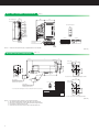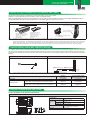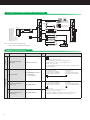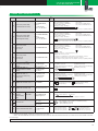
1
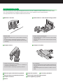
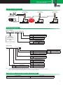
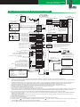
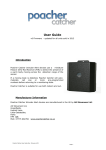
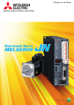
General-Purpose AC Servo MELSERVO-J3W Servo Amplifier MR-J3W-0303BN6 Servo Motor HG-AK Series <10 W to 30 W> March 2013 New Product Release S V 1 2 1 2 - 4 E- A 2-axis integrated type Compact body with high performance Introducing the new ultra-compact servo motor and the compatible servo amplifier that incorporate MR-J3-B servo amplifier’s high potential and popular ease-of-use. t c A MR-J3W-0303BN6 (actual size) l ua e z i s Flange size 25 × 25 mm HG-AK0136 (actual size) Servo Amplifier MR-J3W-0303BN6 Servo Motor HG-AK Series • 48 V DC and 24 V DC are available for the main circuit power supply. • The servo motor with electromagnetic brake is newly released. • The 2-axis integrated type reduces wiring and saves space. • Capacities from 10 W to 30 W with the flange size of 25 mm × 25 mm are available. • Compatible with the high-speed optical network SSCNET III. The functions equivalent to those of MR-J3-B are achieved. • Equipped with 262,144 pulses/rev (18-bit) high-resolution absolute position encoder. • The weight is lighter by max. approx. 35% compared to the prior model for more compact machine. Application Examples • The ultra-compact servo motor with the flange size of 25 mm × 25 mm is suitable for small machines and machine heads. • The 2-axis integrated servo amplifier and ultra-compact servo motor contribute to more compact machine. • The high-performance servo amplifier enables shorter tact time. █ Mounters / bonders █ Machine head • The high-performance servo system enables shorter tact time. • Shorter tact time is achieved by suppressing vibrations. • The high resolution encoder achieves high-accuracy positioning. █ Compact robots Compact machine handling axis • The small-size servo amplifier and servo motor achieve compact machine. • The high resolution encoder achieves high-accuracy positioning. █ Compact robot joint drive and hand • The 2-axis integrated servo amplifier is available for multiple-joint articulated robots. • Shorter tact time is achieved by suppressing vibrations. Semiconductor / LCD manufacturing systems Compact X-Y tables X-Y positioning • The high-performance servo system enables shorter tact time. • The high resolution encoder achieves high-accuracy positioning. • The 2-axis integrated servo amplifier is suitable for the X-Y table. █ Electrical parts manufacturing systems █ Inspection systems █ Electrical devices assembling systems █ Photovoltaic manufacturing systems █ Compact actuators █ Screw tightening systems █ Others 1 █ Processing machines 2-axis AC Servo Amplifier MR-J3W-0303BN6 AC Servo Motor HG-AK Series System Configurations Personal computer Setup software SW1DNC-MRC2-E or MRZJW3-SETUP221E Servo amplifier MR-J3W-0303BN6 Servo amplifier MR-J3W-0303BN6 Servo amplifier MR-J3W-0303BN6 USB cable MR-J3USBCBL3M SSCNET III SSCNET III Controller Different capacity of the motors can be combined. SSCNET III A-axis rotary servo motor B-axis rotary servo motor A-axis rotary servo motor B-axis rotary servo motor A-axis rotary servo motor B-axis rotary servo motor Model Designation Servo amplifier MR-J3W-0303BN6 Symbol Main circuit power supply voltage 6 48 V DC/24 V DC Mitsubishi general-purpose AC servo amplifier MELSERVO-J3W Series (2-axis AC servo amplifier) Symbol BN Symbol 0303 Interface SSCNET III Rated output [W] A-axis (Note 1) B-axis (Note 1) 30 30 Servo motor HG-AK0136B Symbol None B Electromagnetic brake None Installed (Note 2) (Newly released) Symbol Shaft end None Standard (straight shaft) D D-cut shaft (Note 3) Symbol Main circuit power supply voltage 6 48 V DC/24 V DC Symbol Size/capacity HG-AK Ultra-compact size, small capacity Symbol 3 Rated speed [r/min] 3000 Symbol 01 02 03 Rated output [W] 10 20 30 Notes: 1. A-axis and B-axis indicate names of axes of the 2-axis servo amplifier. 2. Refer to "HG-AK Series Electromagnetic Brake Specifications" in this brochure for the available models and detailed specifications. 3. Refer to "HG-AK Series Special Shaft End Specifications" in this brochure for detailed specifications. Combinations of Servo Amplifier and Servo Motor MR-J3W-0303BN6 Servo amplifier Servo motor HG-AK0136, HG-AK0236, HG-AK0336 2 MR-J3W-0303BN6 Specifications Servo amplifier model Rated output Rated voltage Output Rated current (each axis) [A] Voltage (Note 1) Main circuit Rated current power supply Permissible voltage fluctuation Voltage Rated current [A] Permissible voltage fluctuation Power consumption [W] Interface power supply Control method Reusable regenerative [J] energy (Note 2) Capacitor Moment of inertia regeneration (J) equivalent to permissible [× 10-4 kg•m2] charging amount Control circuit power supply 30 W (A-axis) 2.4 MR-J3W-0303BN6 3-phase 48 V AC 30 W (B-axis) 2.4 48 V DC/24 V DC (Note 4) For 48 V DC: 2.4 A/for 24 V DC: 4.8 A For 48 V DC: 40.8 V DC to 55.2 V DC For 24 V DC: 21.6 V DC to 26.4 V DC 24 V DC 0.5 21.6 V DC to 26.4 V DC 10 24 V DC ± 10% (required current capacity: 0.25 A (Note 5)) Sine-wave PWM control/current control method 0.9 0.18 (Note 3) Tolerable regenerative power of the built-in regenerative resistor Dynamic brake Communication function Protective functions Compliance to standards Structure (IP rating) Close mounting Ambient temperature Ambient humidity Environment Ambience Mass Altitude Vibration resistance [W] 1.3 Built-in (Note 6, 7) USB: Connect a personal computer (MR Configurator_ compatible) Overcurrent shut-off, regenerative overvoltage shut-off, overload shut-off (electronic thermal), servo motor overheat protection, encoder error protection, regenerative error protection, undervoltage protection, instantaneous power failure protection, overspeed protection, error excessive protection Refer to "Conformity with Global Standards and Regulations" on p. 6 in this brochure. Natural cooling, open (IP20) Possible (Note 8) 0 °C to 55 °C (non-freezing), storage: -20 °C to 65 °C (non-freezing) 90 %RH maximum (non-condensing), storage: 90 %RH maximum (non-condensing) Indoors (no direct sunlight); no corrosive gas, inflammable gas, oil mist or dust 1000 m or less above sea level 5.9 m/s2 at 10 Hz to 55 Hz (directions of X, Y and Z axes) [kg] 0.3 Notes: 1. Rated output and speed of a servo motor are applicable when the servo amplifier, combined with the servo motor, is operated within the specified power supply voltage. 2. The reusable regenerative energy is the energy generated when a machine, which has a moment of inertia equivalent to the permissible charging amount, decelerates from the rated speed to a stop. 3. The permissible charging amount is equivalent to the moment of inertia when the servo motor decelerates from the rated speed to a stop. When two axes are simultaneously decelerated, the permissible charging amount is equivalent to the total moments of inertia of the two axes. Otherwise, the permissible charging amount is equivalent to the moment of inertia of each axis. 4. Set [Pr. Po04] to "1 _ _ _" to use 24 V DC. 5. 0.25 A is the value when all of the input/output points are used. The current capacity can be stepped down according to the number of input/output points. 6. The dynamic brake is electronic. The electronic dynamic brake does not operate when the control circuit power is off. It may not operate depending on the alarms and the warnings. Refer to "MR-J3W-0303BN6 MR-J3W-B Servo Amplifier Instruction Manual" for details. 7. When using the dynamic brake, refer to "MR-J3W-0303BN6 MR-J3W-B Servo Amplifier Instruction Manual" for the permissible load to motor inertia ratio. 8. When the servo amplifiers are closely mounted, keep the ambient temperature within 0 °C to 45 °C, and use them with 75% or less of the effective load rate. 3 2-axis AC Servo Amplifier MR-J3W-0303BN6 AC Servo Motor HG-AK Series MR-J3W-0303BN6 Standard Wiring Diagram Example R A 4 2B 1A 2A 0 3 PM 2 1 For 24 V DC main circuit 10 m or shorter power supply CN3 (Note 1) Circuit A-axis encoder A-phase pulse LA-A 24 V DC protector (differential line driver) LAR-A A-axis encoder B-phase pulse LB-A (differential line driver) LBR-A B-axis encoder A-phase pulse LA-B (differential line driver) LAR-B B-axis encoder B-phase pulse LB-B (differential line driver) LBR-B Control common LG Analog monitor output (Note 13) Output voltage: 10 V ± 5 V Maximum output current: 1 mA A 1 R A 2 R A 3 R A 4 (Note 3) 24 V DC power supply for interface (Note 9) Controller ● ● ● ● ● ● ● (Note 4) Forced stop A-axis upper stroke limit (FLS) A-axis lower stroke limit (RLS) A-axis proximity dog (DOG) B-axis upper stroke limit (FLS) B-axis lower stroke limit (RLS) B-axis proximity dog (DOG) (Note 6) Q173DCPU Q172DCPU Q173HCPU Q172HCPU Q170MCPU Q170MSCPU (Note 14) QD77MS (Note 14) ● ● ● ● ● ● QD75MH QD74MH LD77MH FX3U-20SSC-H Q173DSCPU (Note 14) Q172DSCPU (Note 14) SD (Note 16) 24 V DC for the electromagnetic brake RA 11 24 12 25 DICOM DOCOM 23 26 EM1 DI1-A DI2-A DI3-A DI1-B DI2-B DI3-B 10 7 8 9 20 21 22 M (Note 16) ElectroB magnetic brake (Note 15) Contact must be open when the malfunction (ALM-A/-B) or the electromagnetic brake interlock (MBR-A/-B) signal turns off. Contact must be open by an external emergency stop switch. CN2A/CN2B 4A 4B P5 LG 5B 1A 1B 5A BAT MR MRR SD 4B 4A CN4 1 2 BAT LG 4B 4A P5 LG 5A BAT 1B MR 1A MRR 5B SD P5 LG 5A BAT 1B MR 1A MRR 5B SD Install the battery set (MR-J3W03BATSET) with the battery mounting attachment and the battery extension cable when configuring absolute position detection system. Plate ALM-A ALM-B MBR-A MBR-B Personal computer (Note 10) USB cable MR-J3USBCBL3M MR-J3BUS_M, MR-J3BUS_M-A/-B cable MR-J3BUS_M, MR-J3BUS_M-A/-B cable Setup software SW1DNC-MRC2-E or MRZJW3-SETUP221E Servo amplifier (Note 7) MR-J3W-0303BN6 3rd and 4th axis Servo amplifier (Note 7) MR-J3W-0303BN6 10 m or shorter MR-J3BUS_M, MR-J3BUS_M-A/-B cable U 2B W 2B W 1A 1A 3A B1 3A B1 3B B2 3B B2 (Note 17) 2 1 15 CN1A A-axis malfunction B-axis malfunction A-axis electromagnetic brake interlock B-axis electromagnetic brake interlock (Note 5) 2 m or shorter (Note 2) R 1B V 1B (Note 16) 3 16 4 17 5 18 6 19 14 MO1 LG MO2 Output voltage: 10 V ± 5 V Maximum output current: 1 mA Built-in regenerative resistor 2A U 1B V Encoder 4 2A U V W CN1B CN1A RA4 (Note 1) 24 U (Note 8) (Note 11) SW1 SW2 0 1 2 Attach a cap to the unused connector. CN1B CN1A CNP1 48 V DC HG-AK servo motor series CNP2A/CNP2B CN5 For 48 V DC main circuit power supply (Note 1) Circuit 24 V DC protector Servo amplifier MR-J3W-0303BN6 (1st and 2nd axis) Malfunction RA1 Controller (A-axis) forced stop EM1 Off On RA3 RA2 (B-axis) Forced stop RA4 CN1B (Note 12) (n-1)th and nth axis Notes: 1. Use 24 V DC and 48 V DC power supplies with reinforced insulation. Additionally, connect the - side wiring (0 V) to the power supply terminal. 2. Do not reverse the diode's direction. Connecting it backwards may cause the servo amplifier to malfunction such that the signals are not output, and the forced stop and other safety circuits are inoperable. 3. Use the power supply 24 V DC ± 10% (required current capacity: 0.25 A). 0.25 A is the value when all of the input/output points are used. The current capacity can be stepped down according to the number of input/output points in use. Refer to "MR-J3W-0303BN6 MR-J3W-B Servo Amplifier Instruction Manual" for details. 4. The forced stop signal is issued for two axes of the servo amplifier. For overall system, apply the emergency stop on the controller side. 5. ALM-A (A-axis malfunction) and ALM-B (B-axis malfunction) (normally closed contact) are conducted to DOCOM in normal alarm-free condition. 6. For details such as setting the controllers, refer to relevant controllers' programming manual or user's manual. 7. Connections for the third and following axes are omitted. 8. Up to 16 axes (n = 2 to 16) can be set using the axis selection rotary switch (SW1). 9. Devices can be assigned for DI1-A/B, DI2-A/B and DI3-A/B with controller setting. Refer to the controller instruction manuals for details on setting. These devices can be assigned with the controller: Q173DCPU,Q172DCPU,Q173HCPU,Q172HCPU,Q170MCPU,QD75MH,QD74MH,LD77MH,Q173DSCPU,Q172DSCPU or QD77MS. 10. This is for sink wiring. Source wiring is also possible. Refer to "MR-J3W-0303BN6 MR-J3W-B Servo Amplifier Instruction Manual" for details. 11. Test operation select switch (SW2-1) is used to perform test operation mode with MR Configurator2 (SW1DNC-MRC2-E) or MR Configurator (MRZJW3-SETUP221E). SW2-2 is for manufacturer setting. 12. This connection is for continuing operation with one axis when an alarm occurs on the other axis. To stop the operation of the both axes with an alarm on one axis, connect RA1 and RA2 in series. 13. Output voltage range varies depending on the monitored signal. 14. Use the controller in SSCNET III mode. 15. This is for the servo motor with electromagnetic brake. The electromagnetic brake terminals (B1, B2) do not have polarity. 16. Noiseless grounding ( ) terminals of CNP2A and CNP2B and noiseless grounding ( ) terminal of CNP1 are connected in the servo amplifier. Connect the noiseless grounding ( ) terminal of CNP1 to the grounding terminal of the cabinet. 17. Do not use the 24 V DC interface power supply for the electromagnetic brake. Provide a dedicated power supply to the electromagnetic brake. 4 HG-AK Series (Ultra-compact Size, Small Capacity) Specifications Servo motor model Compatible servo amplifier model Power supply capacity (Note 1) Rated output Continuous running duty Rated torque (Note 2) Maximum torque Rated speed 48 V DC Maximum speed 24 V DC Permissible 48 V DC instantaneous 24 V DC speed Standard Power rate at With continuous rated electromagnetic torque brake Rated current Maximum current HG-AK 0136(B) [W] [W] [N•m] [N•m] [r/min] [r/min] [r/min] [r/min] 230 10 0.032 0.095 6000 [r/min] 0236(B) MR-J3W-0303BN6 360 20 0.064 0.191 3000 6000 6900 6900 0336(B) 480 30 0.095 0.286 5000 5750 [kW/s] 3.54 9.01 14.95 [kW/s] 2.41 6.99 12.32 [A] [A] [times/ Regenerative braking frequency (Note 3) min] Standard [× 10-4 kg•m2] Moment of inertia With J electromagnetic [× 10-4 kg•m2] brake Recommended load to motor inertia ratio (Note 4) 2.1 6.3 2.1 6.3 2.2 6.6 1700 1200 900 0.0029 0.0045 0.0061 0.0042 0.0058 0.0074 Speed/position detector Oil seal Insulation class Structure Environment (Note 5) Ambient temperature Ambient humidity Ambience Altitude Vibration resistance (Note 6) Vibration rank Compliance to standards L Permissible load Radial for the shaft (Note 7) Thrust Standard With Mass electromagnetic brake [mm] [N] [N] [kg] [kg] 30 times or less Absolute/incremental 18-bit encoder (resolution: 262144 pulses/rev) None 130(B) Totally enclosed, natural cooling (IP rating: IP55) (Note 8) 0 °C to 40 °C (non-freezing), storage: -15 °C to 70 °C (non-freezing) 80 %RH maximum (non-condensing), storage: 90 %RH maximum (non-condensing) Indoors (no direct sunlight); no corrosive gas, inflammable gas, oil mist or dust 1000 m or less above sea level X: 49 m/s2 Y: 49 m/s2 V10 (Note 9) Refer to "Conformity with Global Standards and Regulations" on p. 6 in this brochure. 16 16 16 34 44 49 14 14 14 0.12 0.14 0.16 0.22 Notes:1. The power supply capacity varies depending on the impedance of DC power supply and wiring. 2. When unbalanced torque is generated, such as in a vertical lift machine, it is recommended that the unbalanced torque of the machine be kept under 70% of the servo motor rated torque. 3. The regenerative braking frequency shows the permissible frequency when the servo motor, without a load and a regenerative option, decelerates from the rated speed to a stop. When a load is connected; however, the value will be the table value/(m+1), where m = Moment of inertia of load/Moment of inertia of servo motor. When the operating speed exceeds the rated speed, the regenerative braking frequency is inversely proportional to the square of (operating speed/ rated speed). Take measures to keep the regenerative power [W] during operation below the tolerable regenerative power of built-in regenerative resistor [W]. Use caution, especially when the operating speed changes frequently or when the regeneration is constant (as with vertical feeds). 4. Contact your local sales office if the load to motor inertia ratio exceeds the value in the table. 5. In the environment where the servo motor is exposed to oil mist, oil and/or water, a standard specification servo motor may not be usable. Contact your local sales office for more details. 5 0.24 0.26 Servo motor 6. The vibration direction is shown in the diagram to the right. The numerical value indicates the maximum value of the component (commonly the X Y bracket in the opposite direction of the servo motor shaft). Fretting more likely occurs on the bearing when the servo motor stops. Thus, maintain vibration level at approximately one-half of the allowable value. L Radial load 7. Refer to the diagram to the L: Distance between the flange mounting surface and the right for the permissible load Thrust load center of load for the shaft. Do not apply a load exceeding the value specified in the table on the shaft. The values in the table are applicable when each load is applied singly. Shaft-through portion 8. The shaft-through portion, the connector, and the power cable leading part are excluded. Refer to the diagram to the right for shaftServo motor through portion. 9. V10 indicates that the amplitude of the servo Measuring Top position motor itself is 10 µm or less. The diagram to the right shows mounting posture and Bottom measuring position of the servo motor during the measurement. 2-axis AC Servo Amplifier MR-J3W-0303BN6 AC Servo Motor HG-AK Series HG-AK Series Electromagnetic Brake Specifications Model HG-AK Type Rated voltage Power consumption [W] at 20 °C Electromagnetic brake static friction [N•m] torque Per braking [J] Permissible braking work Per hour [J] Electromagnetic Number of brakings [Times] brake life (Note 2) Work per braking [J] 0136B (Note 1) 0236B Spring actuated type safety brake 24 V DC -100 % 1.8 0336B 0.095 4.6 46 20000 1 Notes: 1. The electromagnetic brake is for holding. It should not be used for deceleration applications. 2. Brake gap is not adjustable. Electromagnetic brake life is defined as the time period until the readjustment is needed. HG-AK Series Torque Characteristics HG-AK0136(B) (Note1, 2) HG-AK0236(B) (Note1, 2) 0 0.4 0.15 0.1 0.05 0 Torque [N•m] Continuous running range 1000 2000 3000 4000 5000 6000 Speed [r/min] Torque [N•m] Torque [N•m] Short-duration running range 0.05 0.025 HG-AK0336(B) (Note1, 2) 0.2 0.1 0.075 (Note 3, 4) Short-duration running range Continuous running range 1000 2000 3000 4000 5000 6000 Speed [r/min] 0.3 Short-duration running range 0.2 0.1 0 Continuous running range 1000 2000 3000 4000 5000 6000 Speed [r/min] Notes: 1. :For 48 V DC. :For 24 V DC. 2. 3. This is applicable when Mitsubishi optional cable MRJ3W03PWCBL5M-A-H or MR-J3W03PWBRCBL5M-A-H is used. 4. Torque drops when the power supply voltage is below the specified value. HG-AK Series Special Shaft End Specifications Motors with the following specifications are also available. D-cut shaft 16 2.5 13 10 0.5 φ5h6 [Unit: mm] Conformity with Global Standards and Regulations (Note 1) MR-J3W series conforms to global standards as standard. Available model Low voltage directive European EC EMC directive (Note 2) directive RoHS directive UL standard CSA standard Measures for Administration of the Pollution Control of Electronic Information Products (Chinese RoHS) China Compulsory Certification (CCC) Korea Radio Wave Law (KC) MR-J3W-0303BN6 EN 61800-5-1 EN 61800-3 Compliant UL 508C CSA C22.2 No.14 HG-AK series EN 60034-1/EN 60034-5 EN 60034-1 Compliant UL 1004-1/UL 1004-6 CSA C22.2 No.100 Compliant (optional cables and connectors) Compliant (optional cables and connectors) N/A Compliant N/A N/A Notes: 1. When exporting the product, follow the local laws and regulations. 2. Refer to "Servo Amplifier Instruction Manual" and "EMC Installation Guidelines" when your system needs to meet the EMC directive. 6 MR-J3W-0303BN6 Dimensions (Note 1) 30 2-φ6 mounting hole (80) 6 100 6 CN5 CN3 SW1 SW2 Terminal arrangement 156 168 CN4 CN1A CNP1 CN1B 24 4 CN2A 0 3 CN2B CNP1 PM 2 1 CNP2B CNP2A 6 6 (23) CNP2A CNP2B (29) U (68) When MR-J3W03BATSET is mounted B W 3 2 V 1 A U B W 3 2 V 1 A Mounting screw size: M5 6 Notes: 1. CNP1 connector (insertion type) is supplied with the servo amplifier. HG-AK Series Dimensions 200 [Unit: mm] (Note 1, 4) +20 0 16 L 8 (Note 5) 2-M3 screw 17.5 * □25 45° φ2 8 φ20h7 2.5 13 φ5h6 * 11.5 5.4 CL 3.4 15.4 12.3 18.6 KL For servo motor without electromagnetic brake □25 A Power connector Power cable Housing: J21DF-06V-KX-L Terminal: SJ2F-01GF-P1.0 321 B 321 A A * The encoder cable leading portion will be modified from April 2013 production. Model HG-AK0136(B) HG-AK0236(B) HG-AK0336(B) 2-M3 screw Pin No. Signal name 1 (E) 2 U A 3 B1 (Note 2) 1 V 2 W B 3 B2 (Note 2) Variable dimensions (Note 3) L KL CL 54 (86) 30.7 (42.7) 225 +20 0 61 (93) 37.7 (49.7) (245 +20 0 ) 68 (100) 44.7 (56.7) 45° φ2 8 17.5 Encoder cable Housing: J21DF-10V-KX-L Terminal: SJ2F-002GF-P1.0 24 For servo motor with electromagnetic brake [Unit: mm] Notes: 1. For dimensions without tolerance, general tolerance applies. 2. The electromagnetic brake terminals (B1, B2) do not have polarity. 3. Dimensions in brackets are for the models with electromagnetic brake. 4. Use a friction coupling to fasten a load. 5. Select the mounting screw whose length is within this dimension. 7 2-axis AC Servo Amplifier MR-J3W-0303BN6 AC Servo Motor HG-AK Series Battery Set (MR-J3W03BATSET) and Battery (MR-J3BAT) The absolute position data can be retained by mounting the battery on the servo amplifier. A battery is not required when the servo system is used in incremental method. When using MR-J3BAT, the battery mounting attachment and the battery extension cable are required. Purchase MR-J3W03BATSET which includes MR-J3BAT, the battery mounting attachment, and the battery extension cable for the first time. Appearance Mounting method Insert the battery extension cable connector to CN4. Connect the battery to the battery extension cable. Model: MR-J3BAT (Note 1) Nominal voltage: 3.6 V Nominal capacity: 2000 mAh Lithium content: 0.65 g Primary battery: ER6 Mass: 25 g * MR-J3W03BATSET: Includes MR-J3BAT, the battery mounting attachment, and the battery extension cable. * MR-J3BAT: Battery Install the battery mounting attachment to the servo amplifier. Notes: 1. MR-J3BAT is a lithium metal battery contains ER6. This battery is not subject to the dangerous goods (Class 9) of the UN Recommendations. To transport lithium metal batteries and lithium metal batteries contained in equipment by means of transport subject to the UN Recommendations, take actions to comply with the following regulations: the United Nations Recommendations on the Transport of Dangerous Goods, the Technical Instruction (ICAO-TI) by the International Civil Aviation Organization (ICAO), and the International Maritime Dangerous Goods Code (IMDG Code) by the International Maritime Organization (IMO). To transport the batteries, check the latest standards or the laws of the destination country and take actions. Contact your local sales office for more details. (As of March 2013) Junction Battery Cable (MR-J3W03BTCBL03M) This cable is used to hold the absolute position data if the servo amplifier has to be removed from a machine for shipping. The servo motor does not have a super capacitor (for holding an absolute position data for short time) in the encoder. When this optional cable is used, the absolute position data can be held even when the encoder cable is disconnected from the servo amplifier, making it easy to do maintenance on the servo amplifier. Appearance Mounting method Servo amplifier CN5 CN3 CN4 CN1A CN1B 0.3 m CN2A CN2B MR-J3W03ENCBL_M-A-H MR-J3W03BTCBL03M (Note 1) (Note 1) Encoder (Note 1) Servo motor (Note 2) CNP1 CNP2A CNP2B MR-J3BAT (Note 1) Notes: 1. To hold the absolute position data, the encoder, the encoder cable, the junction cable and the battery must be kept connected. 2. Use the junction battery cable in combination with the optional encoder cable (MR-J3W03ENCBL_M-A-H) or the encoder connector set (MR-J3W03CN2-_P). User's system Incremental − Not necessary to hold an absolute position data after the encoder cable is disconnected from the servo amplifier Necessary to hold an absolute position data after the encoder cable is disconnected from the servo amplifier (Note 1) Absolute position Battery (MR-J3BAT) Not required Junction battery cable (MR-J3W03BTCBL03M) Not required Required Not required Required Required Notes: 1. Start up the absolute position detection system after connecting this optional cable. Junction Terminal Block (MR-TB26A) Connect all signals via the junction terminal block. Dimensions (Note 1) [Unit: mm] 14 15 16 17 18 19 20 21 22 23 24 25 26 S 1 26 14 Stranded wire Applicable wire (terminal Solid wire side) Insulator OD 27 1 2 3 4 5 6 7 8 9 10 11 12 13 S 1 Rating 55 (35) Specifications 14 Operating tool 57 23.6 26.6 (31.1) (7.5) 739 250V 1.5 739 250V 1.5 Strip length Notes: 1. The lengths in brackets apply when the junction terminal block is mounted on a 35 mm wide DIN rail. 32 V AC/DC, 0.5 A 0.08 mm2 to 1.5 mm2 (AWG 28 to 14) ø0.32 mm to 1.2 mm 3.4 mm or shorter 210-619 (WAGO) or equivalent 210-119SB (WAGO) or equivalent 5 mm to 6 mm 8 Configuration Example for MR-J3W-0303BN6 Servo amplifier CN5 Servo amplifier CN5 CN3 (14) Setup software SW1DNC-MRC2-E or MRZJW3-SETUP221E (15) (16) CN4 CN1A CN4 Junction terminal block MR-TB26A (Note 2) (17) Controller Q173DCPU Q172DCPU Q173HCPU Q172HCPU (12) Q170MCPU QD75MH QD74MH LD77MH FX3U-20SSC-H Q173DSCPU (Note 1) Q172DSCPU (Note 1) Q170MSCPU (Note 1) QD77MS (Note 1) CN3 CN1A CN1B (13) CN1B (9) (10) (11) (9) (10) (11) CN2A CN2A (12) CN2B CNP1 (1) CN2B CNP1 (2) CNP2A CNP2A (3) (4) CNP2B CNP2B (5) Attach a cap to the unused connector. (6) Notes: 1. Use the controller in SSCNET III mode. 2. Refer to "Junction Terminal Block" in this brochure. (7) (8) Servo motor Cables and Connectors (Note 3) For CNP1 Item Servo amplifier power (1) connector Model IP rating Description Power connector (Phoenix Contact) Connector: FK-MCP1,5/4-ST-3,5 or an equivalent product (Standard accessory) − Applicable wire size: 0.14 mm² to 1.5 mm² (AWG 26 to 16) Insulator OD: Up to 2.9 mm * For the standard accessory, the color of this connector is changed, and letters are specially printed. For CN2A/CN2B (2) Encoder cable (3) Encoder connector set (Qty: 2 pcs) MR-J3W03ENCBL_M-A-H _ = cable length: 1, 2, 5, 10, 20, 30 m MR-J3W03CN2-2P − − Servo amplifier connector (TE Connectivity Ltd. Company) Receptacle housing: 1-1827862-5 Receptacle contact: 1827587-2 Encoder connector (J.S.T. Mfg.) Tab housing: J21DPM-10V-KX Tab contact: SJ2M-01GF-M1.0N Servo amplifier connector (TE Connectivity Ltd. Company) Receptacle housing: 1-1827862-5 Receptacle contact: 1827587-2 Encoder connector (J.S.T. Mfg.) Tab housing: J21DPM-10V-KX Tab contact: SJ2M-01GF-M1.0N Applicable cable Wire size: 0.2 mm2 to 0.38 mm2 (AWG 24 to 22) Insulator OD: 1.11 mm to 1.53 mm (4) 9 Encoder connector set (Qty: 20 pcs) MR-J3W03CN2-20P − * Crimping tool (1762846-1) is required for the servo amplifier connector. Crimping tool (YRS-8861) is required for the encoder connector. 2-axis AC Servo Amplifier MR-J3W-0303BN6 AC Servo Motor HG-AK Series Cables and Connectors (Note 3) Item Servo motor power cable (for standard servo motor) Servo motor power cable (6) (for the servo motor with electromagnetic brake) Servo motor power (7) connector set (Qty: 2 pcs) MR-J3W03PWCBL_ M-A-H _ = cable length: 1, 2, 5, 10, 20, 30 m MR-J3W03PWBRCBL_ M-A-H _ = cable length: 1, 2, 5, 10, 20, 30 m MR-J3W03CNP2-2P IP rating − − SSCNET III cable (Note 1) (9) (standard cord for inside cabinet) SSCNET III cable (Note 1) (10) (standard cable for outside cabinet) MR-J3BUS_M _ = cable length: 0.15, 0.3, 0.5, 1, 3 m MR-J3BUS_M-A _ = cable length: 5, 10, 20 m SSCNET III cable (Note 1) (11) (long distance cable, long bending life) MR-J3BUS_M-B _ = cable length: 30, 40, 50 m*1 − − − − − (13) SSCNET III connector cap (Standard accessory) − Personal computer (14) USB cable communication cable MR-J3USBCBL3M Cable length: 3 m For CN3 (17) Junction terminal block cable Servo amplifier connector (TE Connectivity Ltd. Company) Receptacle housing: 1-1827864-3 or an equivalent product Receptacle contact: 1871745-1 Power connector (J.S.T. Mfg.) Tab housing: J21DPM-06V-KX Tab contact: SJ2M-21GF-M1.0N Servo amplifier connector (TE Connectivity Ltd. Company) Receptacle housing: 1-1827864-3 or an equivalent product Receptacle contact: 1871745-1 Power connector (J.S.T. Mfg.) Tab housing: J21DPM-06V-KX Tab contact: BJ2M-21GF-M1.0N MR-J2CMP2 (Qty: 1 pc) MR-ECN1 (Qty: 20 pc) MR-TBNATBL_M _ = cable length: 0.5, 1 m * Crimping tool (1762625-1) is required for the servo amplifier connector. Crimping tool (YRF-1120) is required for the power connector. * The shape of housing used for the servo amplifier connector is partially modified. SSCNET III connector (Japan Aviation Electronics Industry) PF-2D103 (connector) SSCNET III connector (Japan Aviation Electronics Industry) PF-2D103 (connector) SSCNET III connector (Japan Aviation Electronics Industry) CF-2D103-S (connector) SSCNET III connector (Japan Aviation Electronics Industry) CF-2D103-S (connector) − (12) SSCNET III connector set (Note 1, 2) MR-J3BCN1 (16) Power connector (J.S.T. Mfg.) Tab housing: J21DPM-06V-KX Tab contact: SJ2M-21GF-M1.0N * The shape of housing used for the servo amplifier connector is partially modified. For CN1B MR-J3W03CNP2-20P Connector set Servo amplifier connector (TE Connectivity Ltd. Company) Receptacle housing: 1-1827864-3 or an equivalent product Receptacle contact: 1871745-1 Applicable cable Wire size: 0.34 mm2 to 0.75 mm2 (AWG 22 to 19) Insulator OD: 1.4 mm to 1.9 mm Servo motor power (8) connector set (Qty: 20 pcs) (15) Description * The shape of housing used for the servo amplifier connector is partially modified. For CN5 For controller/CN1A/CN1B For CNP2A/CNP2B (5) Model − SSCNET III connector (Japan Aviation Electronics Industry) PF-2D103 (connector) Servo amplifier connector mini-B connector (5 pins) SSCNET III connector (Japan Aviation Electronics Industry) PF-2D103 (connector) Personal computer connector A-connector * Do not use this cable for SSCNET III compatible controller. − − − Servo amplifier connector (3M or an equivalent product) 10126-3000PE (connector) 10326-52F0-008 (shell kit) Junction terminal block connector (3M or an equivalent product) 10126-6000EL (connector) 10326-3210-000 (shell kit) Servo amplifier connector (3M or an equivalent product) 10126-6000EL (connector) 10326-3210-000 (shell kit) Notes: 1. Read carefully through the precautions enclosed with the options before use. 2. Dedicated tools are required. Contact your local sales office for more details. 3. Refer to "MR-J3W-0303BN6 MR-J3W-B Servo Amplifier Instruction Manual" and "Servo Motor Instruction Manual (Vol. 2)" for cables and connectors available on the market. For unlisted lengths *1. For unlisted lengths of the cables, contact Mitsubishi Electric System & Service Co., Ltd. FA PRODUCT DIVISION by email: [email protected] 10 Wires (Example of Selection) The following are examples of wire sizes when 600 V polyvinyl chloride insulated wires (IV wires) or 600 V grade heatresistant polyvinyl chloride insulated wires (HIV wires) with a length of 30 m are used. Servo amplifier model Wire size (Note 1) U, V, W, AWG 19 24, 0, PM, AWG 16 (Note 2) MR-J3W-0303BN6 B1, B2 1.25 mm2 (AWG 16) Notes: 1. This wire size is selected when HG-AK0336(B) is used for two axes. 2. A voltage drop occurs by the current supplied to the servo amplifier according to the wiring impedance. Circuit Protector Power supply specifications Control circuit power supply (24 V DC) Main circuit power supply (48 V DC) Control circuit power supply/main circuit power supply (24 V DC) Circuit protector (Note 1) CP30-BA 1P 1-M 1A CP30-BA 1P 1-M 5A CP30-BA 1P 1-M 10A Notes: 1. Use the circuit protector whose operation characteristics is medium-speed type. Safety Warning To ensure proper use of the products listed in this catalog, please be sure to read the instruction manual prior to use. MDOC (1303) New publication, effective March 2013 Specifications subject to change without notice.