1
YASKAWA
DC Power Input Σ-II Series SGM□J/SGDJ
USER'S MANUAL
AC Servodrives
SGMMJ/SGMAJ Servomotor
SGDJ SERVOPACK
YASKAWA
MANUAL NO. SIE-S800-38C
Copyright © 2000 YASKAWA ELECTRIC CORPORATION
All rights reserved. No part of this publication may be reproduced, stored in a retrieval system,
or transmitted, in any form, or by any means, mechanical, electronic, photocopying, recording,
or otherwise, without the prior written permission of Yaskawa. No patent liability is assumed
with respect to the use of the information contained herein. Moreover, because Yaskawa is constantly striving to improve its high-quality products, the information contained in this manual is
subject to change without notice. Every precaution has been taken in the preparation of this
manual. Nevertheless, Yaskawa assumes no responsibility for errors or omissions. Neither is
any liability assumed for damages resulting from the use of the information contained in this
publication.
About this Manual
Intended Audience
This manual is intended for the following users.
• Those selecting Σ-II Series servodrives or peripheral devices for Σ-II Series servodrives.
• Those wanting to know about the ratings and characteristics of Σ-II Series servodrives.
• Those designing Σ-II Series servodrive systems.
• Those installing or wiring Σ-II Series servodrives.
• Those performing trial operation or adjustments of Σ-II Series servodrives.
• Those maintaining or inspecting Σ-II Series servodrives.
Description of Technical Terms
The terms in this manual are defined as follows:
• Servomotor or motor = DC power input Σ-II Series SGMMJ and SGMAJ servomotor.
• SERVOPACK = DC power input Σ-II Series SGDJ amplifier.
• Servodrive = A set including a servomotor and servo amplifier.
• Servo System = A servo control system that includes the combination of a servodrive with a host
computer and peripheral devices.
• Parameter number = Numbers that the user inputs toward the SERVOPACK.
Indication of Reverse Signals
In this manual, the names of reverse signals (ones that are valid when low) are written with a forward slash (/)
before the signal name, as shown in the following example:
• S-ON = /S-ON
• P-CON = /P-CON
iii
Quick access to your required information
Read the chapters marked with 9 to get the information required for your purpose.
Chapter
SERVOPACKs,
Servomotors,
and Peripheral
Devices
Ratings and
Characteristics
System
Design
Panel
Configura-tion
and Wiring
Chapter 1
Outline
9
Chapter 2
Selections
9
Chapter 3
Specifications and
Dimensional Drawings
9
9
9
9
Chapter 4
SERVOPACK Specifications
and Dimensional Drawings
9
9
9
9
Chapter 5
Specifications and
Dimensional Drawings of
Cables and Peripheral
Devices
9
9
9
9
Chapter 6
Wiring
9
9
Chapter 7
Digital Operator
9
Trial Operation
and Servo
Adjustment
Chapter 8
Operation
Inspection and
Maintenance
9
9
9
Chapter 9
Adjustments
9
Chapter 10
Inspection, Maintenance,
and Troubleshooting
9
9
9
9
■ Visual Aids
The following aids are used to indicate certain types of information for easier reference.
IMPORTANT
• Indicates important information that should be memorized, including precautions such as alarm displays to avoid damaging the devices.
INFO
EXAMPLE
TERMS
iv
• Indicates supplemental information.
• Indicates application examples.
• Indicates definitions of difficult terms or terms that have not been previously explained in this manual.
Related Manuals
Refer to the following manuals as required.
Manual Name
Manual Number
Contents
Σ-II Series SGMH/SGDM
Digital Operator Operation Manual
TOE-S800-34
Provides detailed information on the operating method
of JUSP-OP02A-2 type Digital Operator (option
device).
Σ-II Series SERVOPACKs
Personal Computer Monitoring Software
Operation Manual
SIE-S800-35
Describes the using and the operating methods on software that changes the local personal computer into the
monitor equipment for the Σ-II Series servomotor.
v
Safety Information
The following conventions are used to indicate precautions in this manual. Failure to heed precautions provided
in this manual can result in serious or possibly even fatal injury or damage to the products or to related equipment
and systems.
WARNING
Indicates precautions that, if not heeded, could possibly result in loss of life or serious
injury.
CAUTION
Indicates precautions that, if not heeded, could result in relatively serious or minor
injury, damage to the product, or faulty operation.
In some situations, the precautions indicated could have serious consequences if not heeded.
PROHIBITED
Indicates prohibited actions that must not be performed. For example, this symbol
would be used as follows to indicate that fire is prohibited:
MANDATORY
.
Indicates compulsory actions that must be performed. For example, this symbol would
be used as follows to indicate that grounding is compulsory:
.
The warning symbols for ISO and JIS standards are different, as shown below.
ISO
JIS
The ISO symbol is used in this manual.
Both of these symbols appear on warning labels on Yaskawa products. Please abide by these warning labels
regardless of which symbol is used.
vi
Notes for Safe Operation
Read this manual thoroughly before checking products on delivery, storage and transportation, installation,
wiring, operation and inspection, and disposal of the AC servodrive.
WARNING
• Never touch any rotating motor parts while the motor is running.
Failure to observe this warning may result in injury.
• Before starting operation with a machine connected, make sure that an emergency stop can
be applied at any time.
Failure to observe this warning may result in injury.
• Never touch the inside of the SERVOPACKs.
Failure to observe this warning may result in electric shock.
• Do not touch terminals for five minutes after the power is turned OFF.
Residual voltage may cause electric shock.
• Follow the procedures and instructions for trial operation precisely as described in this manual.
Malfunctions that occur after the servomotor is connected to the equipment not only damage the
equipment, but may also cause an accident resulting in death or injury.
• The multiturn limit value must be changed only for special applications.
Changing it inappropriately or unintentionally can be dangerous.
• If the Multiturn Limit Disagreement alarm (A.CC) occurs, check the setting of parameter
Pn205 in the SERVOPACK to be sure that it is correct.
If Fn013 is executed when an incorrect value is set in Pn205, an incorrect value will be set in the
encoder. The alarm will disappear even if an incorrect value is set, but incorrect positions will be
detected, resulting in a dangerous situation where the machine will move to unexpected positions.
• Do not remove the cables and connector items while the power is ON.
Failure to observe this warning may result in electric shock.
• Do not damage, press, exert excessive force or place heavy objects on the cables.
Failure to observe this warning may result in electric shock, stopping operation of the product, or
burning.
• Provide an appropriate stopping device on the machine side to ensure safety. A holding
brake for a servomotor with brake is not a stopping device for ensuring safety.
Failure to observe this warning may result in injury.
• Do not come close to the machine immediately after resetting momentary power loss to
avoid an unexpected restart. Take appropriate measures to ensure safety against an
unexpected restart.
Failure to observe this warning may result in injury.
• Connect the ground terminal to electrical codes (ground resistance: 100 Ω or less).
Improper grounding may result in electric shock or fire.
• Installation, disassembly, or repair must be performed only by authorized personnel.
Failure to observe this warning may result in electric shock or injury.
• Do not modify the product.
Failure to observe this warning may result in injury or damage to the product.
vii
Checking on Delivery
CAUTION
• Always use the servomotor and SERVOPACK in one of the specified combinations.
Failure to observe this caution may result in fire or malfunction.
Storage and Transportation
CAUTION
• Do not store or install the product in the following places.
• Locations subject to direct sunlight.
• Locations subject to temperatures outside the range specified in the storage or installation temperature conditions.
• Locations subject to humidity outside the range specified in the storage or installation humidity conditions.
• Locations subject to condensation as the result of extreme changes in temperature.
• Locations subject to corrosive or flammable gases.
• Locations subject to dust, salts, or iron dust.
• Locations subject to exposure to water, oil, or chemicals.
• Locations subject to shock or vibration.
Failure to observe this caution may result in fire, electric shock, or damage to the product.
• Do not hold the product by the cables or motor shaft while transporting it.
Failure to observe this caution may result in injury or malfunction.
• Do not place any load exceeding the limit specified on the packing box.
Failure to observe this caution may result in injury or malfunction.
Installation
CAUTION
• Never use the products in an environment subject to water, corrosive gases, inflammable gases, or
combustibles.
Failure to observe this caution may result in electric shock or fire.
• Do not step on or place a heavy object on the product.
Failure to observe this caution may result in injury.
• Do not cover the inlet or outlet parts and prevent any foreign objects from entering the product.
Failure to observe this caution may cause internal elements to deteriorate resulting in malfunction or fire.
• Be sure to install the product in the correct direction.
Failure to observe this caution may result in malfunction.
• Provide the specified clearances between the SERVOPACK and the control panel or with other devices.
Failure to observe this caution may result in fire or malfunction.
• Do not apply any strong impact.
Failure to observe this caution may result in malfunction.
viii
Wiring
CAUTION
• Do not connect a three-phase power supply to the U, V, or W output terminals.
Failure to observe this caution may result in injury or fire.
• Securely connect the power supply terminals and motor output terminals.
Failure to observe this caution may result in fire.
• Do not bundle or run power and signal lines together in the same duct. Keep power and signal lines
separated by at least 30 cm (11.81 in).
Failure to observe this caution may result in malfunction.
• Use twisted-pair shielded wires or multi-core twisted pair shielded wires for signal and encoder (PG)
feedback lines.
The maximum length is 3 m (118.11 in) for reference input lines and is 20 m (787.40 in) for PG feedback lines.
• Do not touch the power terminals for five minutes after turning power OFF because high voltage may still
remain in the SERVOPACK.
Make sure the charge indicator is turned OFF first before starting an inspection.
• Avoid frequently turning power ON and OFF. Do not turn power ON or OFF more than once per minute.
A high charging current flows for 0.2 seconds in the SERVOPACK when power is turned ON. Frequently turning
power ON and OFF causes main power devices such as capacitors and fuses to deteriorate, resulting in unexpected
problems.
• Observe the following precautions when wiring main circuit terminal blocks.
• Remove the terminal block from the SERVOPACK prior to wiring.
• Insert only one wire per terminal on the terminal block.
• Make sure that the core wire is not electrically shorted to adjacent core wires.
• Install the battery at either the host controller or the SERVOPACK of the encoder.
It is dangerous to install batteries at both simultaneously, because that sets up a loop circuit between the batteries.
• Be sure to wire correctly and securely.
Failure to observe this caution may result in motor overrun, injury, or malfunction.
• Always use the specified power supply voltage.
An incorrect voltage may result in damage to the SERVOPACK and burning.
• Take appropriate measures to ensure that the input power supply is supplied within the specified voltage
fluctuation range. Be particularly careful in places where the power supply is unstable.
An incorrect power supply may result in damage to the product.
• Install external breakers or other safety devices against short-circuiting in external wiring.
Failure to observe this caution may result in fire.
• Take appropriate and sufficient countermeasures for each when installing systems in the following
locations.
• Locations subject to static electricity or other forms of noise.
• Locations subject to strong electromagnetic fields and magnetic fields.
• Locations subject to possible exposure to radioactivity.
• Locations close to power supplies including power supply lines.
Failure to observe this caution may result in damage to the product.
• Do not reverse the polarity of the battery when connecting it.
Failure to observe this caution may damage the battery or cause it to explode.
ix
Operation
CAUTION
• Conduct trial operation on the servomotor alone with the motor shaft disconnected from machine to avoid
any unexpected accidents.
Failure to observe this caution may result in injury.
• Before starting operation with a machine connected, change the settings to match the parameters of the
machine.
Starting operation without matching the proper settings may cause the machine to run out of control or malfunction.
• Forward run prohibited (P-OT) and reverse run prohibited (N-OT) signals are not effective during zero point
search mode using parameter Fn003.
• When using the servomotor for a vertical axis, install the safety devices to prevent workpieces to fall off due
to occurrence of alarm or overtravel. Set the servomotor so that it will stop in the zero clamp state at
occurrence of overtravel.
Failure to observe this caution may cause workpieces to fall off due to overtravel.
• When not using the normal autotuning, set to the correct moment of inertia ratio.
Setting to an incorrect moment of inertia ratio may cause vibration.
• Do not touch the SERVOPACK heatsinks or servomotor while power is ON or soon after the power is turned
OFF.
Failure to observe this caution may result in burns due to high temperatures.
• Do not make any extreme adjustments or setting changes of parameters.
Failure to observe this caution may result in injury due to unstable operation.
• When an alarm occurs, remove the cause, reset the alarm after confirming safety, and then resume
operation.
Failure to observe this caution may result in injury.
• Do not use the servo brake of the servomotor for ordinary braking.
Failure to observe this caution may result in malfunction.
Maintenance and Inspection
CAUTION
• When replacing the SERVOPACK, transfer the previous SERVOPACK parameters to the new
SERVOPACK before resuming operation.
Failure to observe this caution may result in damage to the product.
• Do not attempt to change wiring while the power is ON.
Failure to observe this caution may result in electric shock or injury.
• Do not disassemble the servomotor.
Failure to observe this caution may result in electric shock or injury.
Disposal
CAUTION
• When disposing of the products, treat them as ordinary industrial waste.
x
General Precautions
Note the following to ensure safe application.
• The drawings presented in this manual are sometimes shown without covers or protective guards. Always replace
the cover or protective guard as specified first, and then operate the products in accordance with the manual.
• The drawings presented in this manual are typical examples and may not match the product you received.
• This manual is subject to change due to product improvement, specification modification, and manual
improvement. When this manual is revised, the manual code is updated and the new manual is published as a next
edition.
• If the manual must be ordered due to loss or damage, inform your nearest Yaskawa representative or one of the
offices listed on the back of this manual.
• Yaskawa will not take responsibility for the results of unauthorized modifications of this product. Yaskawa shall
not be liable for any damages or troubles resulting from unauthorized modification.
xi
CONTENTS
About this Manual - - - - - - - - - - - - - - - - - - - - - - - - - - - - - - - - - - - - - - iii
Related Manuals - - - - - - - - - - - - - - - - - - - - - - - - - - - - - - - - - - - - - - - -v
Safety Information - - - - - - - - - - - - - - - - - - - - - - - - - - - - - - - - - - - - - - vi
Notes for Safe Operation - - - - - - - - - - - - - - - - - - - - - - - - - - - - - - - - - vii
1 Outline
1.1 Checking Products - - - - - - - - - - - - - - - - - - - - - - - - - - - - - - 1-2
1.1.1 Check Items - - - - - - - - - - - - - - - - - - - - - - - - - - - - - - - - - - - - - - - - - 1-2
1.1.2 Servomotors - - - - - - - - - - - - - - - - - - - - - - - - - - - - - - - - - - - - - - - - - 1-2
1.1.3 SERVOPACKs- - - - - - - - - - - - - - - - - - - - - - - - - - - - - - - - - - - - - - - - 1-3
1.2 Product Part Names - - - - - - - - - - - - - - - - - - - - - - - - - - - - - 1-4
1.2.1 Servomotors Without Gears and Brakes - - - - - - - - - - - - - - - - - - - - - 1-4
1.2.2 SERVOPACKs - - - - - - - - - - - - - - - - - - - - - - - - - - - - - - - - - - - - - - - 1-5
1.3 Examples of Servo System Configurations - - - - - - - - - - - - - 1-6
1.4 Applicable Standards - - - - - - - - - - - - - - - - - - - - - - - - - - - - 1-7
1.4.1 North American Safety Standards (UL, CSA) - - - - - - - - - - - - - - - - - - 1-7
1.4.2 CE Marking - - - - - - - - - - - - - - - - - - - - - - - - - - - - - - - - - - - - - - - - - - 1-7
2 Selections
2.1 Servomotor Model Designations - - - - - - - - - - - - - - - - - - - - 2-2
2.1.1 Model SGMMJ- - - - - - - - - - - - - - - - - - - - - - - - - - - - - - - - - - - - - - - - 2-2
2.1.2 Model SGMAJ - - - - - - - - - - - - - - - - - - - - - - - - - - - - - - - - - - - - - - - - 2-4
2.2 SERVOPACK Model Designations - - - - - - - - - - - - - - - - - - - 2-6
2.3 SGDJ SERVOPACKs and Applicable Servomotors - - - - - - - 2-7
2.4 Selecting Cables - - - - - - - - - - - - - - - - - - - - - - - - - - - - - - - 2-8
2.5 Selecting Peripheral Devices- - - - - - - - - - - - - - - - - - - - - - 2-12
2.5.1
2.5.2
2.5.3
2.5.4
Special Options - - - - - - - - - - - - - - - - - - - - - - - - - - - - - - - - - - - - - Molded-case Circuit Breaker and Fuse Capacity- - - - - - - - - - - - - - AC/DC Power Supply and Power Supply Input Capacitor - - - - - - - Noise Filters, Surge Suppressors, Magnetic Conductors, and Brake
Power Supply - - - - - - - - - - - - - - - - - - - - - - - - - - - - - - - - - - - - - - -
2-12
2-13
2-14
2-15
3 Specifications and Dimensional Drawings
3.1 Ratings and Specifications of SGMMJ (3000 min-1) - - - - - - - 3-2
3.1.1 SGMMJ Servomotors Without Gears - - - - - - - - - - - - - - - - - - - - - - - - 3-2
3.1.2 SGMMJ Servomotors With Standard Backlash Gears - - - - - - - - - - - - 3-4
xii
3.2 Ratings and Specifications of SGMAJ (3000min-1) - - - - - - - 3-5
3.2.1 SGMAJ Servomotors Without Gears - - - - - - - - - - - - - - - - - - - - - - - -3-5
3.2.2 SGMAJ Servomotors With Standard Backlash Gears- - - - - - - - - - - - -3-8
3.2.3 SGMAJ Servomotors With Low-backlash Gears - - - - - - - - - - - - - - - 3-10
3.3 Mechanical Specifications of SGMMJ and SGMAJ
Servomotors - - - - - - - - - - - - - - - - - - - - - - - - - - - - - - - - - 3-12
3.3.1 Precautions on Servomotor Installation - - - - - - - - - - - - - - - - - - - - - - 3-12
3.3.2 Mechanical Characteristics of SGMMJ Servomotors - - - - - - - - - - - - 3-14
3.3.3 Mechanical Characteristics of SGMAJ Servomotors- - - - - - - - - - - - - 3-15
3.4 Terms and Data for Servomotors With Gears - - - - - - - - - - 3-17
3.5 Dimensional Drawings of SGMMJ Servomotors (3000min-1) 3-19
3.5.1 SGMMJ Servomotors (3000min-1) Standard and Without Brakes - - - 3-19
3.5.2 SGMMJ Servomotors (3000min-1) Standard and With Brakes- - - - - - 3-20
3.5.3 SGMMJ Servomotor (3000min-1) With Gears and Without Brakes- - - 3-21
3.5.4 SGMMJ Servomotors (3000min-1) With Gears and Brakes - - - - - - - - 3-23
3.6 Dimensional Drawings of SGMAJ Servomotors (3000 min-1)3-25
3.6.1 SGMAJ Servomotors (3000 min-1) Without Gears - - - - - - - - - - - - - - 3-25
3.6.2 SGMAJ Servomotors (3000 min-1) Without Gears and With Brakes- - 3-28
3.6.3 SGMAJ Servomotors (3000 min-1) With Standard Backlash Gears
and Without Brakes - - - - - - - - - - - - - - - - - - - - - - - - - - - - - - - - - - - 3-30
3.6.4 SGMAJ Servomotors (3000 min-1) With Standard Backlash Gears
and Brakes - - - - - - - - - - - - - - - - - - - - - - - - - - - - - - - - - - - - - - - - - 3-35
3.6.5 SGMAJ Servomotors (3000 min-1) With Low-backlash Gears and
Without Brakes- - - - - - - - - - - - - - - - - - - - - - - - - - - - - - - - - - - - - - - 3-39
3.7 Dimensional Drawing of Output Shafts With Oil Seals - - - - 3-43
4 SERVOPACK Specifications and Dimensional Drawings
4.1 SERVOPACK Ratings and Specifications - - - - - - - - - - - - - - 4-2
4.1.1 SERVOPACK Ratings and Specifications 1 - - - - - - - - - - - - - - - - - - - -4-2
4.1.2 SERVOPACK Ratings and Specifications 2 - - - - - - - - - - - - - - - - - - - -4-3
4.2 SERVOPACK Installation - - - - - - - - - - - - - - - - - - - - - - - - - 4-5
4.3 SERVOPACK Internal Block Diagrams - - - - - - - - - - - - - - - - 4-7
4.3.1 Speed and Torque Control (SGDJ-S) - - - - - - - - - - - - - - - - - - - -4-7
4.3.2 Position Control (SGDJ-P) - - - - - - - - - - - - - - - - - - - - - - - - - - -4-8
4.4 SERVOPACK’s Power Supply Capacities and Power Losses 4-9
4.5 SERVOPACK Overload Characteristics and Allowable Load
Moment of Inertia - - - - - - - - - - - - - - - - - - - - - - - - - - - - - - 4-10
4.5.1
4.5.2
4.5.3
4.5.4
Overload Characteristics - - - - - - - - - - - - - - - - - - - - - - - - - - - - - - - - 4-10
Starting and Stopping Time - - - - - - - - - - - - - - - - - - - - - - - - - - - - - - 4-11
Load Moment of Inertia - - - - - - - - - - - - - - - - - - - - - - - - - - - - - - - - - 4-11
Overhanging Loads - - - - - - - - - - - - - - - - - - - - - - - - - - - - - - - - - - - 4-12
xiii
4.6 Dimensional Drawings - - - - - - - - - - - - - - - - - - - - - - - - - - 4-13
4.6.1 24 VDC: 10/50 W (A1C/A5C)
48 VDC: 50 W to 200 W (A5E to 02E) - - - - - - - - - - - - - - - - - - - 4-13
4.6.2 24 VDC: 80 W (A8C)
48 VDC: 300 W (03E) - - - - - - - - - - - - - - - - - - - - - - - - - - - - - - - - 4-13
5 Specifications and Dimensional Drawings of Cables and
Peripheral Devices
5.1 Specifications and Dimensional Drawings of Servomotor Main
Circuit Cable - - - - - - - - - - - - - - - - - - - - - - - - - - - - - - - - - - 5-2
5.1.1 Cables for SGMMJ and SGMAJ Servomotors Without Brakes - - - - - - 5-2
5.1.2 Cables for SGMMJ and SGMAJ Servomotors With Brakes - - - - - - - - 5-3
5.2 Servomotor and SERVOPACK Main Circuit Wire Size and
Connectors - - - - - - - - - - - - - - - - - - - - - - - - - - - - - - - - - - - 5-4
5.2.1 Wire Size - - - - - - - - - - - - - - - - - - - - - - - - - - - - - - - - - - - - - - - - - - - 5-4
5.2.2 SGMMJ Servomotor Connectors for Standard Environments - - - - - - - 5-5
5.2.3 SGMAJ Servomotor Connectors for Standard Environments - - - - - - - 5-6
5.3 Encoder Cables for CN4 Connector - - - - - - - - - - - - - - - - - 5-10
5.3.1 Encoder Cable With Connectors - - - - - - - - - - - - - - - - - - - - - - - - - - 5-10
5.3.2 Encoder Cable With a SERVOPACK Connector and Encoder Loose
Leads - - - - - - - - - - - - - - - - - - - - - - - - - - - - - - - - - - - - - - - - - - - - - 5-10
5.4 Connectors and Cables for Encoder Signals - - - - - - - - - - - 5-11
5.4.1 Connectors and Cables - - - - - - - - - - - - - - - - - - - - - - - - - - - - - - - - 5-11
5.5 I/O Signal Cables for CN1 Connector - - - - - - - - - - - - - - - - 5-13
5.5.1 Standard Cables - - - - - - - - - - - - - - - - - - - - - - - - - - - - - - - - - - - - - 5-13
5.5.2 Connector Type and Cable Size - - - - - - - - - - - - - - - - - - - - - - - - - - 5-13
5.5.3 Connection Diagram - - - - - - - - - - - - - - - - - - - - - - - - - - - - - - - - - - 5-15
5.6 Peripheral Devices - - - - - - - - - - - - - - - - - - - - - - - - - - - - - 5-16
5.6.1
5.6.2
5.6.3
5.6.4
5.6.5
5.6.6
5.6.7
5.6.8
Cables for Connecting Personal Computers - - - - - - - - - - - - - - - - - Digital Operator - - - - - - - - - - - - - - - - - - - - - - - - - - - - - - - - - - - - - Cables for Analog Monitor - - - - - - - - - - - - - - - - - - - - - - - - - - - - - Connector Terminal Block Converter Unit - - - - - - - - - - - - - - - - - - - Noise Filter - - - - - - - - - - - - - - - - - - - - - - - - - - - - - - - - - - - - - - - - Surge Suppressor - - - - - - - - - - - - - - - - - - - - - - - - - - - - - - - - - - - Variable Resistor for Speed and Torque Setting - - - - - - - - - - - - - - Encoder Signal Converter Unit - - - - - - - - - - - - - - - - - - - - - - - - - - -
5-16
5-17
5-18
5-19
5-21
5-21
5-21
5-22
6 Wiring
6.1 Wiring Main Circuit - - - - - - - - - - - - - - - - - - - - - - - - - - - - - - 6-2
6.1.1 Names and Functions of Main Circuit Terminals - - - - - - - - - - - - - - - - 6-2
6.1.2 Wiring Main Circuit Power Supply Connector - - - - - - - - - - - - - - - - - - 6-3
6.1.3 Typical Main Circuit Wiring Examples - - - - - - - - - - - - - - - - - - - - - - - 6-4
xiv
6.2 Wiring Encoders- - - - - - - - - - - - - - - - - - - - - - - - - - - - - - - - 6-5
6.2.1 Connecting an Encoder (CN2) and Output Signals from
the SERVOPACK (CN1) - - - - - - - - - - - - - - - - - - - - - - - - - - - - - - - - -6-5
6.2.2 Encoder Connector (CN2) Terminal Layout - - - - - - - - - - - - - - - - - - - -6-6
6.3 Examples of I/O Signal Connections - - - - - - - - - - - - - - - - - 6-7
6.3.1
6.3.2
6.3.3
6.3.4
6.3.5
6.3.6
SGDJ-S for Speed Control Mode- - - - - - - - - - - - - - - - - - - - - - -6-7
SGDJ-P for Position Control Mode - - - - - - - - - - - - - - - - - - - - -6-8
SGDJ-S for Torque Control Mode - - - - - - - - - - - - - - - - - - - - - -6-9
I/O Signal Connector (CN1) Terminal Layout - - - - - - - - - - - - - - - - - - 6-10
I/O Signal (CN1) Names and Functions - - - - - - - - - - - - - - - - - - - - - 6-12
Interface Circuit - - - - - - - - - - - - - - - - - - - - - - - - - - - - - - - - - - - - - - 6-14
6.4 Others - - - - - - - - - - - - - - - - - - - - - - - - - - - - - - - - - - - - - - 6-17
6.4.1
6.4.2
6.4.3
6.4.4
6.4.5
Wiring Precautions - - - - - - - - - - - - - - - - - - - - - - - - - - - - - - - - - - - - 6-17
Wiring for Noise Control - - - - - - - - - - - - - - - - - - - - - - - - - - - - - - - - 6-18
Installation Conditions of EMC Directives - - - - - - - - - - - - - - - - - - - - 6-21
Using More Than One SERVOPACK - - - - - - - - - - - - - - - - - - - - - - - 6-23
Extending Encoder Cables - - - - - - - - - - - - - - - - - - - - - - - - - - - - - - 6-24
7 Digital Operator
7.1 Functions on Digital Operator - - - - - - - - - - - - - - - - - - - - - - 7-2
7.1.1
7.1.2
7.1.3
7.1.4
Connecting the Digital Operator - - - - - - - - - - - - - - - - - - - - - - - - - - - -7-2
Key Names and Functions - - - - - - - - - - - - - - - - - - - - - - - - - - - - - - -7-3
Basic Mode Selection and Operation - - - - - - - - - - - - - - - - - - - - - - - -7-4
Status Display - - - - - - - - - - - - - - - - - - - - - - - - - - - - - - - - - - - - - - - -7-5
7.2 Operation in Utility Function Mode (Fn) - - - - - - - - - - - 7-7
7.2.1
7.2.2
7.2.3
7.2.4
7.2.5
7.2.6
List of Utility Function Modes - - - - - - - - - - - - - - - - - - - - - - - - - - - - - -7-7
Alarm Traceback Data Display (Fn000)- - - - - - - - - - - - - - - - - - - - - - -7-8
Zero-point Search Mode (Fn003) - - - - - - - - - - - - - - - - - - - - - - - - - - -7-9
Parameter Settings Initialization (Fn005)- - - - - - - - - - - - - - - - - - - - - 7-10
Alarm Traceback Data Clear (Fn006) - - - - - - - - - - - - - - - - - - - - - - - 7-11
Automatic Offset-adjustment of Motor Current Detection Signal
(Fn00E) - - - - - - - - - - - - - - - - - - - - - - - - - - - - - - - - - - - - - - - - - - - - 7-12
7.2.7 Manual Offset-adjustment of Motor Current Detection Signal
(Fn00F) - - - - - - - - - - - - - - - - - - - - - - - - - - - - - - - - - - - - - - - - - - - - 7-13
7.2.8 Password Setting (Protects Parameters from Being Changed)
(Fn010) - - - - - - - - - - - - - - - - - - - - - - - - - - - - - - - - - - - - - - - - - - - - 7-14
7.2.9 Motor Models Display (Fn011) - - - - - - - - - - - - - - - - - - - - - - - - - - - - 7-15
7.2.10 Software Version Display (Fn012) - - - - - - - - - - - - - - - - - - - - - - - - 7-16
7.3 Operation in Parameter Setting Mode (Pn)- - - - - - - - 7-17
7.3.1 Setting Parameters - - - - - - - - - - - - - - - - - - - - - - - - - - - - - - - - - - - - 7-17
7.3.2 Input Circuit Signal Allocation - - - - - - - - - - - - - - - - - - - - - - - - - - - - 7-21
7.3.3 Output Circuit Signal Allocation - - - - - - - - - - - - - - - - - - - - - - - - - - - 7-24
7.4 Operation in Monitor Mode (Un) - - - - - - - - - - - - - - - 7-26
7.4.1 List of Monitor Modes - - - - - - - - - - - - - - - - - - - - - - - - - - - - - - - - - - 7-26
xv
8 Operation
8.1 Trial Operation - - - - - - - - - - - - - - - - - - - - - - - - - - - - - - - - - 8-4
8.1.1
8.1.2
8.1.3
8.1.4
8.1.5
Trial Operation for Servomotor without Load- - - - - - - - - - - - - - - - - - - 8-6
Trial Operation for Servomotor without Load from Host Reference - - - 8-9
Trial Operation with the Servomotor Connected to the Machine - - - - 8-15
Servomotor with Brakes - - - - - - - - - - - - - - - - - - - - - - - - - - - - - - - - 8-16
Position Control by Host Controller - - - - - - - - - - - - - - - - - - - - - - - - 8-16
8.2 Control Mode Selection- - - - - - - - - - - - - - - - - - - - - - - - - - 8-17
8.3 Setting Common Basic Functions - - - - - - - - - - - - - - - - - - 8-18
8.3.1
8.3.2
8.3.3
8.3.4
8.3.5
8.3.6
Setting the Servo ON Signal - - - - - - - - - - - - - - - - - - - - - - - - - - - - Switching the Servomotor Rotation Direction - - - - - - - - - - - - - - - - Setting the Overtravel Limit Function - - - - - - - - - - - - - - - - - - - - - - Setting for Holding Brakes - - - - - - - - - - - - - - - - - - - - - - - - - - - - - Selecting the Stopping Method After Servo OFF - - - - - - - - - - - - - - Instantaneous Power Loss Settings - - - - - - - - - - - - - - - - - - - - - - - -
8-18
8-19
8-20
8-22
8-25
8-26
8.4 Absolute Encoders - - - - - - - - - - - - - - - - - - - - - - - - - - - - - 8-27
8.4.1
8.4.2
8.4.3
8.4.4
8.4.5
8.4.6
8.4.7
8.4.8
Interface Circuits - - - - - - - - - - - - - - - - - - - - - - - - - - - - - - - - - - - - Selecting an Absolute Encoder - - - - - - - - - - - - - - - - - - - - - - - - - - Handling Batteries - - - - - - - - - - - - - - - - - - - - - - - - - - - - - - - - - - - Replacing Batteries - - - - - - - - - - - - - - - - - - - - - - - - - - - - - - - - - - Absolute Encoder Setup (Fn008)- - - - - - - - - - - - - - - - - - - - - - - - - Absolute Encoder Reception Sequence - - - - - - - - - - - - - - - - - - - - Multiturn Limit Setting - - - - - - - - - - - - - - - - - - - - - - - - - - - - - - - Multiturn Limit Setting When Multiturn Limit Disagreement (A.CC)
Occurred- - - - - - - - - - - - - - - - - - - - - - - - - - - - - - - - - - - - - - - - - - -
8-28
8-29
8-29
8-29
8-30
8-31
8-35
8-36
8.5 Operating Using Speed Control with Analog Reference - - - 8-37
8.5.1
8.5.2
8.5.3
8.5.4
8.5.5
8.5.6
8.5.7
8.5.8
Setting Parameters - - - - - - - - - - - - - - - - - - - - - - - - - - - - - - - - - - Setting Input Signals - - - - - - - - - - - - - - - - - - - - - - - - - - - - - - - - - Adjusting Offset - - - - - - - - - - - - - - - - - - - - - - - - - - - - - - - - - - - - - Soft Start - - - - - - - - - - - - - - - - - - - - - - - - - - - - - - - - - - - - - - - - - - Speed Reference Filter- - - - - - - - - - - - - - - - - - - - - - - - - - - - - - - - Using the Zero Clamp Function - - - - - - - - - - - - - - - - - - - - - - - - - - Encoder Signal Output - - - - - - - - - - - - - - - - - - - - - - - - - - - - - - - - Speed Coincidence Output - - - - - - - - - - - - - - - - - - - - - - - - - - - - - -
8-37
8-38
8-39
8-42
8-42
8-42
8-44
8-46
8.6 Operating Using Position Control - - - - - - - - - - - - - - - - - - - 8-47
8.6.1
8.6.2
8.6.3
8.6.4
8.6.5
8.6.6
8.6.7
xvi
Setting Parameters - - - - - - - - - - - - - - - - - - - - - - - - - - - - - - - - - - Setting the Electronic Gear - - - - - - - - - - - - - - - - - - - - - - - - - - - - - Position Reference- - - - - - - - - - - - - - - - - - - - - - - - - - - - - - - - - - - Smoothing- - - - - - - - - - - - - - - - - - - - - - - - - - - - - - - - - - - - - - - - - Positioning Completed Output Signal- - - - - - - - - - - - - - - - - - - - - - Positioning Near Signal - - - - - - - - - - - - - - - - - - - - - - - - - - - - - - - Reference Pulse Inhibit Function (INHIBIT) - - - - - - - - - - - - - - - - - -
8-47
8-49
8-52
8-56
8-57
8-58
8-59
8.7 Operating Using Torque Control- - - - - - - - - - - - - - - - - - - - 8-60
8.7.1
8.7.2
8.7.3
8.7.4
Setting Parameters - - - - - - - - - - - - - - - - - - - - - - - - - - - - - - - - - - - - 8-60
Torque Reference Input- - - - - - - - - - - - - - - - - - - - - - - - - - - - - - - - - 8-60
Adjusting the Reference Offset - - - - - - - - - - - - - - - - - - - - - - - - - - - 8-61
Limiting Servomotor Speed during Torque Control - - - - - - - - - - - - - - 8-63
8.8 Operating Using Speed Control with an Internally Set
Speed - - - - - - - - - - - - - - - - - - - - - - - - - - - - - - - - - - - - - - 8-65
8.8.1 Setting Parameters - - - - - - - - - - - - - - - - - - - - - - - - - - - - - - - - - - - - 8-65
8.8.2 Input Signal Settings - - - - - - - - - - - - - - - - - - - - - - - - - - - - - - - - - - - 8-66
8.8.3 Operating Using an Internally Set Speed- - - - - - - - - - - - - - - - - - - - - 8-66
8.9 Limiting Torque- - - - - - - - - - - - - - - - - - - - - - - - - - - - - - - - 8-68
8.9.1
8.9.2
8.9.3
8.9.4
Internal Torque Limit (Limiting Maximum Output Torque) - - - - - - - - - 8-68
External Torque Limit (Output Torque Limiting by Input Signals) - - - - 8-69
Torque Limiting Using an Analog Voltage Reference - - - - - - - - - - - - 8-71
Torque Limiting Using an External Torque Limit and Analog Voltage
Reference - - - - - - - - - - - - - - - - - - - - - - - - - - - - - - - - - - - - - - - - - - 8-72
8.9.5 Checking Output Torque Limiting during Operation - - - - - - - - - - - - - 8-73
8.10 Control Mode Selection - - - - - - - - - - - - - - - - - - - - - - - - - 8-74
8.10.1 Setting Parameters - - - - - - - - - - - - - - - - - - - - - - - - - - - - - - - - - - - 8-74
8.10.2 Switching the Control Mode - - - - - - - - - - - - - - - - - - - - - - - - - - - - - 8-74
8.11 Other Output Signals- - - - - - - - - - - - - - - - - - - - - - - - - - - 8-76
8.11.1 Servo Alarm Output (ALM) and Alarm Code Output
(ALO1, ALO2, ALO3) - - - - - - - - - - - - - - - - - - - - - - - - - - - - - - - - - - 8-76
8.11.2 Warning Output (/WARN)- - - - - - - - - - - - - - - - - - - - - - - - - - - - - - - 8-77
8.11.3 Running Output Signal (/TGON) - - - - - - - - - - - - - - - - - - - - - - - - - - 8-77
8.11.4 Servo Ready (/S-RDY) Output - - - - - - - - - - - - - - - - - - - - - - - - - - - 8-78
9 Adjustments
9.1 Autotuning - - - - - - - - - - - - - - - - - - - - - - - - - - - - - - - - - - - - 9-2
9.1.1 Servo Gain Adjustment Methods - - - - - - - - - - - - - - - - - - - - - - - - - - -9-2
9.1.2 List of Servo Adjustment Functions - - - - - - - - - - - - - - - - - - - - - - - - -9-3
9.2 Online Autotuning- - - - - - - - - - - - - - - - - - - - - - - - - - - - - - - 9-5
9.2.1
9.2.2
9.2.3
9.2.4
9.2.5
9.2.6
9.2.7
Online Autotuning - - - - - - - - - - - - - - - - - - - - - - - - - - - - - - - - - - - - - -9-5
Online Autotuning Procedure - - - - - - - - - - - - - - - - - - - - - - - - - - - - - -9-6
Selecting the Online Autotuning Execution Method - - - - - - - - - - - - - -9-7
Machine Rigidity Setting for Online Autotuning - - - - - - - - - - - - - - - - -9-8
Method for Changing the Machine Rigidity Setting - - - - - - - - - - - - - - -9-9
Saving the Results of Online Autotuning - - - - - - - - - - - - - - - - - - - - - 9-10
Procedure for Saving the Results of Online Autotuning - - - - - - - - - - 9-10
9.3 Manual Tuning - - - - - - - - - - - - - - - - - - - - - - - - - - - - - - - - 9-11
9.3.1
9.3.2
9.3.3
9.3.4
9.3.5
Explanation of Servo Gain - - - - - - - - - - - - - - - - - - - - - - - - - - - - - - - 9-11
Servo Gain Manual Tuning - - - - - - - - - - - - - - - - - - - - - - - - - - - - - - 9-12
Position Loop Gain - - - - - - - - - - - - - - - - - - - - - - - - - - - - - - - - - - - - 9-12
Speed Loop Gain - - - - - - - - - - - - - - - - - - - - - - - - - - - - - - - - - - - - - 9-13
Speed Loop Integral Time Constant - - - - - - - - - - - - - - - - - - - - - - - - 9-13
xvii
9.4 Servo Gain Adjustment Functions - - - - - - - - - - - - - - - - - - 9-14
9.4.1
9.4.2
9.4.3
9.4.4
9.4.5
9.4.6
9.4.7
9.4.8
9.4.9
Feed-forward Reference- - - - - - - - - - - - - - - - - - - - - - - - - - - - - - - Torque Feed-forward - - - - - - - - - - - - - - - - - - - - - - - - - - - - - - - - - Proportional Control Operation (Proportional Operation Reference) Using the Mode Switch (P/PI Switching)- - - - - - - - - - - - - - - - - - - - Setting the Speed Bias - - - - - - - - - - - - - - - - - - - - - - - - - - - - - - - - Speed Feedback Filter - - - - - - - - - - - - - - - - - - - - - - - - - - - - - - - - Speed Feedback Compensation - - - - - - - - - - - - - - - - - - - - - - - - - Switching Gain Settings - - - - - - - - - - - - - - - - - - - - - - - - - - - - - - - Torque Reference Filter - - - - - - - - - - - - - - - - - - - - - - - - - - - - - - - -
9-14
9-15
9-16
9-17
9-20
9-20
9-21
9-23
9-24
9.5 Analog Monitor- - - - - - - - - - - - - - - - - - - - - - - - - - - - - - - - 9-26
9.5.1 Related Parameters - - - - - - - - - - - - - - - - - - - - - - - - - - - - - - - - - - - 9-27
9.5.2 Manual Zero Adjustment and Gain Adjustment of Analog Monitor
Output (Fn00C, Fn00D) - - - - - - - - - - - - - - - - - - - - - - - - - - - - - - - - 9-28
10 Inspection, Maintenance, and Troubleshooting
10.1 Troubleshooting - - - - - - - - - - - - - - - - - - - - - - - - - - - - - - 10-2
10.1.1
10.1.2
10.1.3
10.1.4
Alarm Display Table - - - - - - - - - - - - - - - - - - - - - - - - - - - - - - - - - - 10-2
Warning Display- - - - - - - - - - - - - - - - - - - - - - - - - - - - - - - - - - - - - 10-4
Troubleshooting of Alarm and Warning- - - - - - - - - - - - - - - - - - - - - 10-5
Troubleshooting for Malfunction without Alarm Display - - - - - - - - 10-13
10.2 Inspection and Maintenance - - - - - - - - - - - - - - - - - - - - 10-18
10.2.1 Servomotor Inspection - - - - - - - - - - - - - - - - - - - - - - - - - - - - - - - 10-18
10.2.2 SERVOPACK Inspection- - - - - - - - - - - - - - - - - - - - - - - - - - - - - - 10-18
10.2.3 SERVOPACK’s Parts Replacement Schedule- - - - - - - - - - - - - - - 10-19
10.3 Connection to Host Controller - - - - - - - - - - - - - - - - - - - 10-20
10.3.1 Example of Connection to MP920 4-axes Analog Module SVA-01 10-20
10.3.2 Example of Connection to CP-9200SH Servo Controller
Module SVA (SERVOPACK in Speed Control Mode) - - - - - - - - - - 10-21
10.3.3 Example of Connection to MEMOCON GL120/130 Series Motion
Module MC20 - - - - - - - - - - - - - - - - - - - - - - - - - - - - - - - - - - - - - 10-22
10.3.4 Example of Connection to MEMOCON GL60/70 Series
Positioning Module B2813 (SERVOPACK in Position Control Mode)10-23
10.3.5 Example of Connection to OMRON’s Motion Control Unit - - - - - - 10-24
10.3.6 Example of Connection to OMRON’s Position Control Unit - - - - - 10-25
10.3.7 Example of Connection to OMRON’s Position Control Unit
C500-NC221 (SERVOPACK in Speed Control Mode) - - - - - - - - - 10-26
10.3.8 Example of Connection to OMRON’s Position Control Unit
C500-NC112 (SERVOPACK in Position Control Mode) - - - - - - - - 10-27
10.3.9 Example of Connection to MITSUBISHI’s AD72 Positioning Unit
(SERVOPACK in Speed Control Mode) - - - - - - - - - - - - - - - - - - - 10-28
10.3.10 Example of Connection to MITSUBISHI’s AD75 Positioning Unit
(SERVOPACK in Position Control Mode) - - - - - - - - - - - - - - - - - 10-29
10.4 List of Parameters - - - - - - - - - - - - - - - - - - - - - - - - - - - 10-30
10.4.1 Utility Functions List - - - - - - - - - - - - - - - - - - - - - - - - - - - - - - - - - 10-30
10.4.2 List of Parameters - - - - - - - - - - - - - - - - - - - - - - - - - - - - - - - - - - 10-31
10.4.3 Monitor Modes- - - - - - - - - - - - - - - - - - - - - - - - - - - - - - - - - - - - - 10-47
xviii
INDEX
Revision History
xix
1
1
Outline
1.1 Checking Products - - - - - - - - - - - - - - - - - - - - - - - - - - - - - - - - - - - - - - - - 1-2
1.1.1 Check Items - - - - - - - - - - - - - - - - - - - - - - - - - - - - - - - - - - - - - - - - - - - - - - - - - - - - - 1-2
1.1.2 Servomotors - - - - - - - - - - - - - - - - - - - - - - - - - - - - - - - - - - - - - - - - - - - - - - - - - - - - - 1-2
1.1.3 SERVOPACKs - - - - - - - - - - - - - - - - - - - - - - - - - - - - - - - - - - - - - - - - - - - - - - - - - - - 1-3
1.2 Product Part Names - - - - - - - - - - - - - - - - - - - - - - - - - - - - - - - - - - - - - - - 1-4
1.2.1 Servomotors Without Gears and Brakes - - - - - - - - - - - - - - - - - - - - - - - - - - - - - - - - - 1-4
1.2.2 SERVOPACKs - - - - - - - - - - - - - - - - - - - - - - - - - - - - - - - - - - - - - - - - - - - - - - - - - - - 1-5
1.3 Examples of Servo System Configurations - - - - - - - - - - - - - - - - - - - - - - - 1-6
1.4 Applicable Standards - - - - - - - - - - - - - - - - - - - - - - - - - - - - - - - - - - - - - - 1-7
1.4.1 North American Safety Standards (UL, CSA) - - - - - - - - - - - - - - - - - - - - - - - - - - - - - - 1-7
1.4.2 CE Marking - - - - - - - - - - - - - - - - - - - - - - - - - - - - - - - - - - - - - - - - - - - - - - - - - - - - - - 1-7
1-1
1 Outline
1.1.1 Check Items
1.1 Checking Products
The following procedure is used to check the AC servodrives of Σ-ΙΙ Series products on delivery.
1.1.1 Check Items
Check the following items when Σ-ΙΙ Series products are delivered.
Check Items
Comments
Are the delivered products the ones
that were ordered?
Does the servomotor shaft rotate
smoothly?
Is there any damage?
Check the model numbers marked on the nameplates on the servomotor and SERVOPACK. (Refer to the descriptions of model numbers in
the following section.)
The servomotor shaft is normal if it can be turned smoothly by hand.
Servomotors with brakes, however, cannot be turned manually.
Check the overall appearance, and check for damage or scratches that
may have occurred during shipping.
If any of the above items are faulty or incorrect, contact your Yaskawa representative or the dealer from whom
you purchased the products.
1.1.2 Servomotors
(1) SGMMJ
AC SERVO MOTOR
Servomotor model
Rated output
Rated speed
Serial number
SGMMJ-A1CAA21
2.1A
Ins.B
10W 24V
03 / 09
3 0 0 0 m i n -1
379526-1-1-1
Rated output current
Manufacturing date
YASKAWA ELECTRIC CO. JAPAN
(2) SGMAJ
AC SERVO MOTOR
SGMAJ-A5CAA21
Servomotor model
W
Ratings
Order number
Serial number
Nxm
A
50 V 24
2.9
min-1
0.159
3000 Ins. B
O/N 9271316-1
S/N DD 9964567890012
YASKAWA ELECTRIC CORPORATION JAPAN
1-2
1.1 Checking Products
1.1.3 SERVOPACKs
SERVOPACK model
SERVOPACK MODEL SGDJ-A5CP
Applicable
power supply
Order number
Serial number
DC-INPUT
24V
4.0A
AC-OUTPUT
3PH 0-24V
2.9A 0.05W
O/N 60A 194-341-7
S/N D001Y3265990007
Applicable motor capacity
C
UL
R
US
LISTED
1
YASKAWA ELECTRIC
MADE IN JAPAN
1-3
1 Outline
1.2.1 Servomotors Without Gears and Brakes
1.2 Product Part Names
1.2.1 Servomotors Without Gears and Brakes
(1) SGMMJ
Servomotor connector
Encoder connector
Servomotor
main circuit cable
Encoder cable
Nameplate (Back side)
Output shaft
Encoder
(Detecting section)
(2) SGMAJ
Encoder connector
Servomotor connector
Servomotor main
circuit cable
Encoder cable
Nameplate (Back side)
Output shaft
1-4
Encoder
(Detecting section)
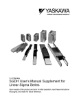
1.2 Product Part Names
1.2.2 SERVOPACKs
CN5 Analog monitor connector
Used to monitor motor speed, torque
reference, and other values through
a special cable.
Refer to 5.6.3 Cables for Analog Monitor or
9.5 Analog Monitor.
Ready indicator
Green lights: Control power supply and main circuit current can be turned ON, and servomotors can be operated.
Red lights: Cannot be operated. (when alarms occurs.)
1
CN3 Connector for personal computer monitoring
and digital operator
Used to communicate with a personal computer or to connect a digital operator.
Refer to 5.6.1 Cables for Connecting Personal Computer and 5.6.2 Digital Operator.
CN8 Servomotor terminals and ground terminals
Connects to the servomotor power line.
Refer to 6.1 Wiring Main Circuit.
CN1 I/O signal connector
Used for reference input signals and
sequence I/O signals.
Refer to 6.3 Examples of I/O Signal Connections.
Nameplate (side view)
Indicates the SERVOPACK model and ratings.
Refer to 1.1.3 SERVOPACKs.
CN9 Main circuit power supply terminals and ground terminals
Used for main circuit power supply input.
Refer to 6.1 Wiring Main Circuit.
CN7 Control power supply terminals
Used for control power supply input.
Refer to 6.1 Wiring Main Circuit.
CN4 Encoder connector
Connects to the encoder in the servomotor.
Refer to 6.2 Wiring Encoders.
1-5
1 Outline
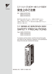
1.3 Examples of Servo System Configurations
This section describes examples of basic servo system configuration.
Power supply Single-phase 100/200 VAC
R T
Note: 24-VDC power supply for servomotor brake must be purchased by customers.
Molded-case
circuit breaker (MCCB) Protects the power supply line by shutting the circuit OFF when
overcurrent is detected.
SGDJ-C
SGDJ-E
SERVOPACK
Digital
operator
Noise filter
(Refer to 5.7.2.)
Used to eliminate
external noise from the power line.
(Refer to 5.7.5.)
Connection cable
for digital operator
(Refer to 5.7.2.)
Personal computer
Connection cable for personal computer
(Refer to 5.7.1.)
CN3
AC/DC
Power supply
− +
Host controller
I/O signal cable
CN8
CN1
CN9
Magnetic contactor
(Refer to 5.6.)
CN7
Turns the servo
power supply
ON or OFF.
Install a surge protector.
CN4
Encoder cable
(Refer to 5.3, 5.4.)
U
V
W
Ground line
1-6
Fuse
SGMJ
Servomotor
1.4 Applicable Standards
1.4 Applicable Standards
Σ-II Series servodrives conform to the following overseas standards.
1.4.1 North American Safety Standards (UL, CSA)
C
UL
R
R
US
C
LISTED
Model
UL∗1 Standards (UL File No.)
SERVOPACK
• SGDJ
UL508C(E147823)
Servomotor
• SGMMJ
• SGMAJ
UL1004(E165827)
US
CSA∗2 Standards
CSA C22.2
No.14
1
Certifications
UL
CSA C22.2
No.100
* 1. Underwriters Laboratories Inc.
* 2. Canadian Standards Association.
1.4.2 CE Marking
Model
SERVOPACK
• SGDJ
Servomotor
• SGMMJ
• SGMAJ
Low Voltage
Directive
EN50178
IEC60034-1
IEC60034-5
IEC60034-8
IEC60034-9
EMC Directive
EMI
EMS
EN55011
group 1 class A
EN50082-2
or
EN61000-6-2
Certifications
TÜV PS∗
* TÜV Product Services GmbH
Note: For installation conditions, refer to 6.4.2 Wiring for Noise Control.
Because SERVOPACKs and servomotors are built-in type, reconfirmation is required after being
installed in the final product.
1-7
2
Selections
2
2.1 Servomotor Model Designations - - - - - - - - - - - - - - - - - - - - - - - - - - - - - - 2-2
2.1.1 Model SGMMJ - - - - - - - - - - - - - - - - - - - - - - - - - - - - - - - - - - - - - - - - - - - - - - - - - - - 2-2
2.1.2 Model SGMAJ - - - - - - - - - - - - - - - - - - - - - - - - - - - - - - - - - - - - - - - - - - - - - - - - - - - - 2-4
2.2 SERVOPACK Model Designations - - - - - - - - - - - - - - - - - - - - - - - - - - - - - 2-6
2.3 SGDJ SERVOPACKs and Applicable Servomotors - - - - - - - - - - - - - - - - - 2-7
2.4 Selecting Cables - - - - - - - - - - - - - - - - - - - - - - - - - - - - - - - - - - - - - - - - - 2-8
2.5 Selecting Peripheral Devices - - - - - - - - - - - - - - - - - - - - - - - - - - - - - - - - 2-12
2.5.1 Special Options - - - - - - - - - - - - - - - - - - - - - - - - - - - - - - - - - - - - - - - - - - - - - - - - - 2.5.2 Molded-case Circuit Breaker and Fuse Capacity - - - - - - - - - - - - - - - - - - - - - - - - - 2.5.3 AC/DC Power Supply and Power Supply Input Capacitor - - - - - - - - - - - - - - - - - - - 2.5.4 Noise Filters, Surge Suppressors, Magnetic Conductors, and Brake Power Supply - -
2-12
2-13
2-14
2-15
2-1
2 Selections
2.1.1 Model SGMMJ
2.1 Servomotor Model Designations
This section explains how to check the servomotor model and ratings. The alphanumeric codes after SGMH
indicate the specifications.
2.1.1 Model SGMMJ
(1) Standard Type
1st + 3rd 4th 5th 6th 7th 8th
2nd
digits digits digits digits digits digits digits
SGMMJ − A1 C A A 2 1
Σ-mini series
SGMMJ servomotor
1st + 2nd digits:
Rated Output
(W)
Code
Rated Output
A1
10
A2
20
A3
30
8th digit: Option
Code
3rd digit: Power Supply Voltage
Code
Voltage
C
24V
E
48V
Specifications
Blank
Leads length 300mm (11.81 in.)
H
Leads length 500mm (19.69 in.)
J
Leads length 1000mm (39.37 in.)
K
Leads length 1500mm (59.06 in.)
7th digit: Brake and Oil Seal
Code Specifications
1
Without brakes
C
24-VDC brake
6th digit: Shaft End
4th digit: Serial Encoder
Code Specifications
Code
Remarks
A
13-bit incremental encoder ∗1
Standard
2
17-bit absolute encoder ∗2
Standard
∗1. The number of encoder pulses: 2048 P/Rev.
∗2. The number of encoder pulses: 32768 P/Rev. 2-2
Specifications
Remarks
2
Straight without flat
Standard
A
Straight with flat
Option
5th digit: Design Revision Order
Code
Specifications
A
Fixed
2.1 Servomotor Model Designations
(2) With Gears
1st + 2nd 3rd 4th 5th 6th 7th 8th 9th 10th
digits digits digits digits digits digits digits digits digits
SGMMJ − A1 C A A J 1 2 1
Σ-mini series
SGMMJ servomotor
10th digit: Option
Code
Code
Code
Rated Output
A1
10
A2
20
A3
30
Blank
Leads length 300mm (11.81 in.)
H
Leads length 500mm (19.69 in.)
3rd digit: Power Supply Voltage
1st + 2nd digits:
Rated Output
(W)
Voltage
C
24V
E
48V
Specifications
J
Leads length 1000mm (39.37 in.)
K
Leads length 1500mm (59.06 in.)
2
9th digit: Brake and Oil Seal
Code Specifications
1
Without brakes
C
24-VDC brake
8th digit: Shaft End
4th digit: Serial Encoder
Code Specifications
Code Specifications
Remarks
A
13-bit incremental encoder ∗1
Standard
2
17-bit absolute encoder ∗2
Standard
∗1. The number of encoder pulses: 2048 P/Rev.
∗2. The number of encoder pulses: 32768 P/Rev. 5th digit: Design Revision Order
Code
Specifications
A
Fixed
6th digit: Gears
Remarks
2
Straight without flat
Standard
6
Straight with key and tap
Option
7th digit: Gear Ratio
Code Specifications
1
1/5
2
1/16
3
1/25
A
1/5
Code
Specifications
B
1/16
J
With gears
C
1/25
Remarks
For SGMMJ-A3
(Gear ratio flange: 40)
For SGMMJ-A1 and A2
(Gear ratio flange: 25)
2-3
2 Selections
2.1.2 Model SGMAJ
2.1.2 Model SGMAJ
(1) Standard Type
1st + 2nd 3rd 4th 5th 6th 7th
digits digits digits digits digits digits
SGMAJ − A5 C A A 2 1
1st + 2nd digits:
Rated Output 3rd digit: Voltage
C: 24-VDC, E: 48-VDC
(kW)
Code
Rated Output
A5
7th digit: Brake and Oil Seal
Code Specifications
1
E
C
0.05
−
A8
0.08
01
0.1
−
02
0.2
−
03
0.3
−
Code
2
4th digit: Serial Encoder
Specifications
1 16-bit absolute encoder Remarks
∗1 Standard
4 16-bit absolute encoder ∗1
with super capacitor
Option
A 13-bit incremental encoder∗2 Standard
B 16-bit incremental encoder∗1 Option
2-4
S
With oil seal
C
With 24-VDC brake
E
With oil seal and 24-VDC brake
6th digit: Shaft End
{: Available
Code
Without options
∗1
The number of encoder pulses: 16384 P/Rev.
∗2
The number of encoder pulses: 2048 P/Rev. Specifications
Straight without key
Standard
4
Straight with key
Option
6
Straight with key and tap
5th digits: Design Revision Order
Code Specifications
A
Remarks
Fixed
2.1 Servomotor Model Designations
(2) With Gears
1st + 2nd 3rd 4th 5th 6th 7th 8th 9th
digits digits digits digits digits digits digits digits
SGMAJ − A5 C A A J 1 2 1
9th digit: Brake
DC power supply input Σ-II series
SGMAJ servomotor
Code
Specifications
1
Without brake
C
With 24-VDC brake
6th digit: Gear TypeCode
8th digit: Shaft End
1st + 2nd digit:
Rated Output (kW)
Code Rated Output Code Specifications
3rd digit: Voltage
C: 24-VDC, D: 48-VDC
A
A5
0.05
A8
0.08
01
0.1
−
02
0.2
−
03
0.3
−
B
Straight without key
−
6
Straight with key and tap
−
J
−
−
2
−
8th digit (Shaft End Code): 2, 6, 8
1st + 2nd + 3rd digits:
6 digit: 7th digit:
Code of the Rated Gear Ratio
Output and Voltage
Gear Type
Specifi03
Code Code cations A5 A8 01 02
Code
Specifications
Remarks
1
16-bit absolute encoder ∗1
Standard
4
16-bit absolute encoder ∗1
with super capacitor
A
13-bit incremental encoder ∗2 Standard
B
16-bit incremental encoder ∗1 Option
Option
1/33
C
1/21
−
1/9
1/11
−
−
−
−
8th digit (Shaft End Code): 2, 6
1st + 2nd + 3rd digits:
5th digit: Design Revision Order
Code Specifications
Fixed
6 digit: 7th digit:
Code of the Rated Output and Voltage
Gear Gear Ratio
Type Code Specifications A5 A8 01 02 03
Code
J
8th digit: G
HDS planetary low-backlash gear
Shaft End Code
0
H
HDS planetary low-backlash gear
2 6 8
J
Standard backlash gear Specifications
1/5
{: Available
The number of encoder pulses: 16384 P/Rev.
6th digit: Gear Type
1
(Low- 2
back- 7
lash) B
H
∗2 The number of encoder pulses: 2048 P/Rev. A
H
−
Straight with tap
{: Available
−
4th digit: Serial Encoder
Code
2
8
{: Available
∗1
G
No shaft
0
1
1/5
3/31
(Low- 3
back- 7
1/33
lash) C
1/21
{: Available
2 6
2-5
2 Selections
2.2 SERVOPACK Model Designations
Select the SERVOPACK according to the applied servomotor.
1st + 2nd
digits
3rd
4th
5th 6th 7th digits digits digits digits digits
SGDJ - A5 E S
Y32
DC power supply
Σ-II series SGDJ SERVOPACK
5th and 7the digits: Conformed to SGMMJ Servomotors
1st + 2nd digits: Rated Output of Applicable Servomotor (W)
2-6
SERVOPACK for SGMAJ and SGMMJA2C, A3C is blank.
Code
Rated Output
A1
10
A2
20
A3
30
A5
50
A8
80
01
100
Code
Voltage
02
200
E
48 VDC
03
300
C
24 VDC
4 digit: Control Mode
Code
Remarks
S
For speed and torque control
P
For position control
3 digit: Voltage
2.3 SGDJ SERVOPACKs and Applicable Servomotors
2.3 SGDJ SERVOPACKs and Applicable Servomotors
Servomotor
SGMMJ
24 VDC
SGMAJ
SGMMJ
48 VDC
SGMAJ
A1C
A2C
A3C
A5C
A8C
A1E
A2E
A3E
A5E
01E
02E
03E
SGDJ SERVOPACK
24 VDC
48 VDC
A1CY32
−
A5C
−
A8C
−
A5C
−
A8C
−
−
A1EY32
−
A2EY32
−
A3EY32
−
A5E
−
01E
−
02E
−
03E
2
2-7
2 Selections
2.4 Selecting Cables
FG
c
CN4
d
e
2-8
2.4 Selecting Cables
Name
Cable with connectors at both ends
Length
3m
(9.84 ft)
5m
(16.4 ft)
10 m
(32.8 ft)
15 m
(49.2 ft)
20 m
(65.6 ft)
3m
(9.84 ft)
Cable with loose
wire at encoder
end
c
CN4
Encoder
Cable
5m
(16.4 ft)
10 m
(32.8 ft)
15 m
(49.2 ft)
20 m
(65.6 ft)
Type
Reference
Specifications
JZSP-CMP00-03
JZSP-CMP00-05
JZSP-CMP00-10
SERVOPACK end
Encoder
end
5.3.1
JZSP-CMP00-15
2
JZSP-CMP00-20
JZSP-CMP03-03
JZSP-CMP03-05
SERVOPACK end
Encoder
end
5.3.2
JZSP-CMP03-10
JZSP-CMP03-15
JZSP-CMP03-20
Soldered
SERVOPACK end
connector kit
JZSP-CMP9-1
Soldered
Encoder end connector kit
5m
(16.4 ft)
Cables
10 m
(32.8 ft)
15 m
(49.2 ft)
20 m
(65.6 ft)
30 m
(98.4 ft)
40 m
(131.2 ft)
50 m
(164.0 ft)
JZSP-CMP9-2
JZSP-CMP09-05
JZSP-CMP09-10
20 m (65.6 ft) max.
5.4.1
JZSP-CMP09-15
JZSP-CMP09-20
JZSP-CMP19-30
JZSP-CMP19-40
50 m (164.0 ft) max.
JZSP-CMP19-50
2-9
2 Selections
Name
d
Servomotor Main
Circuit
Cables
and Connectors
Length
3m
(9.84 ft)
5m
(16.4 ft)
SGMMJ
10 m
Without brakes
(32.8 ft)
15 m
(49.2 ft)
20 m
(65.6 ft)
3m
(9.84 ft)
5m
(16.4 ft)
SGMMJ
10 m
With brakes
(32.8 ft)
15 m
(49.2 ft)
20 m
(65.6 ft)
3m
(9.84 ft)
5m
(16.4 ft)
SGMAJ
10 m
Without brakes
(32.8 ft)
15 m
(49.2 ft)
20 m
(65.6 ft)
3m
(9.84 ft)
5m
(16.4 ft)
SGMAJ
10 m
With brakes
(32.8 ft)
15 m
(49.2 ft)
20 m
(65.6 ft)
SGMMJ connector kit without
brakes
SGMMJ
connector kit with brakes
2-10
Type
(cont’d)
Reference
Specifications
JZSP-CDM00-03
JZSP-CDM00-05
JZSP-CDM00-10
SERVOPACK
end
Seromotor
end
JZSP-CDM00-15
JZSP-CDM00-20
5.2.2
JZSP-CDM10-03
JZSP-CDM10-05
SERVOPACK
end
Seromotor
end
JZSP-CDM10-10
JZSP-CDM10-15
JZSP-CDM10-20
JZSP-CJM00-03
JZSP-CJM00-05
SERVOPACK
end
Seromotor
end
JZSP-CJM00-10
5.1.1
JZSP-CJM00-15
JZSP-CJM00-20
JZSP-CJM10-03
JZSP-CJM10-05
JZSP-CJM10-10
SERVOPACK
end
Seromotor
end
5.1.2
JZSP-CJM10-15
JZSP-CJM10-20
JZSP-CFM9-2
5.2.2
JZSP-CFM9-3
2.4 Selecting Cables
Name
d
Servomotor Main
Circuit
Cables
and Connectors
(Cont’d)
Length
SGMAJ connector kit with
brakes
Type
JZSP-CMM9-1
5.2.2
SGMAJ connector kit with
brakes
For SERVOPACK power supply input connector kit
JZSP-CMM9-2
JZSP-CJG9-2
e
Servomotor Connection
Connector Kit
Specifications
(cont’d)
Reference
SERVOPACK power
supply input + servomotor cables connection
connector kit
JZSP-CJG9-3
The following connectors sets are
available for purchase.
• For the control power supply
(CN7)
• For the main circuit power supply (CN9)
The following connectors sets are
available for purchase.
• For the control power supply
(CN7)
• For the servomotor main circuit
(CN8)
• For the main circuit power supply (CN9)
2
5.2.2
For a flexible cable, contact your Yaskawa representative.
2-11
2 Selections
2.5.1 Special Options
2.5 Selecting Peripheral Devices
2.5.1 Special Options
gAnalog monitor cable
Digital operator
eConnection cable for
digital operator
CN5
f Connection cable for personal
Personal computer
computer
CN3
c I/O signal cable
Host controller
CN1
h Battery for absolute encoder
* Install the battery for the absolute encoder on the side of the host controller.
Name
Length
Connector terminal block
converter unit
c
CN1
I/O Signal
Cables
Cable with
loose wires at
one end
Connector kit
2-12
Type
Specifications
Reference
Terminal block and 0.5 m (1.64 ft)
connection cable
5.6.4
JUSP-TA36P
1m
JZSP-VAI01-1
(3.28 ft)
2m
JZSP-VAI01-2
(6.56 ft)
3m
JZSP-VAI01-3
(9.84 ft)
JZSP-VAI09
Loose wires at host controller end
5.5.1
5.5.2
2.5 Selecting Peripheral Devices
Name
Length
Type
Specifications
(cont’d)
Reference
With connection cable (1 m (3.28 ft))
d Digital Operator
JUSP-OP02A-2
1m
JZSP-CMS00-1
(3.28 ft)
1.5m
JZSP-CMS00-2
(4.92 ft)
2m
JZSP-CMS00-3
(6.56 ft)
e CN3
Connection Cable for Digital Operator
Only required when using Σ series
Digital Operator JUSP-OP02A-1.
SERVOPACK end
5.6.2
Operator end
2
D-Sub 25-pin (For PC98)
SERVOPACK
end
2m
JZSP-CMS01
(6.56 ft)
Personal
computer end
D-Sub 9-pin (For DOS/V)
f CN3
2m
JZSP-CMS02
(6.56 ft)
Connection Cable for Personal
Computer
SERVOPACK
end
Personal
computer end
5.6.1
Half-pitch 14-pin (For PC 98)
2m
JZSP-CMS03
(6.56 ft)
g CN5
1m
JZSP-CA01 or
(3.28 ft) DE9404559
Analog Monitor Cable
h
SERVOPACK
end
CN8
ER6VC3
Battery for Absolute Encoder
Personal
computer end
SERVOPACK end
Monitor end
To connect to a host controller (provided by a customer)
3.6 V 2000 mAh,
manufactured by Toshiba Battery
Co., Ltd.
5.6.3
5.6.8
2.5.2 Molded-case Circuit Breaker and Fuse Capacity
SERVOPACK
model
SGDJ-A5C
SGDJ-A8C
SGDJ-A5E
SGDJ-01E
SGDJ-02E
SGDJ-03E
Voltage
Capacity
(W)
24 VDC
50
80
48 VDC
50
100
200
300
Power Supply Capacity per
SERVOPACK (kVA)
Continuous
Momentary
Rating (W)
Rating (W)
96.6
220
144
320
92.1
170
322
467
210
380
700
1000
Current Capacity of the Fuse and the
Molded-case Circuit Breaker
Power Supply
Power Supply
100 VAC (Arms)
200 VAC (Arms)
15
7.5
20
10
15
22
40
60
7.5
11
20
30
Note: 1. Connect the fuse or the molded-case circuit breaker to the DC side on the control power supply.
2. Select a fuse and a molded-case circuit breaker that are certified by the UL and the CSA and have CE
Marking.
2-13
2 Selections
2.5.3 AC/DC Power Supply and Power Supply Input Capacitor
The following table shows the fuse or the molded-case circuit breaker specifications.
Control Power
Supply Voltage
Applicable
SERVOPACK
24 VDC
48 VDC
C
E
IMPORTANT
Fuse or Molded-case Circuit Breaker Specifications
Rating Voltage (V)
Rating Current (Arms)
30
2.0
60
1.0
The SGDJ SERVOPACK does not include a protective grounding circuit. Install a ground-fault protector to
protect the system against overload and short-circuit or protective grounding combined with the molded-case
circuit breaker.
2.5.3 AC/DC Power Supply and Power Supply Input Capacitor
The SGDJ SERVOPACK requires DC power supply. Select an AC/DC power supply that corresponds with the
voltage of the SERVOPACK. The following table shows the recommended power supply and the power supply
input capacitor.
SERVOPACK
Model
SGDJ-C
SGDJ-E
Applicable
SERVOPACK
Voltage
24 VDC
48 VDC
Recommended AC/DC Power Supply
Model
JWS240P-24
JWS480P-48
Manufacturer
Densei-Lambda K.K.
* Use a power supply with double insulation that is certified and meets safety standards (UL1950 or EN 60950).
SERVOPACK
Voltage
Model
Power Supply Input
SGDJC
Control Power Supply
Input
24 VDC
Main Circuit A5C
Power Supply A8C
SGDJE
Control Power Supply
Input
A5E
48 VDC
01E
Main Circuit
Power Supply 02E
03E
Recommended Power Supply Input Capacitor Specification per
SERVOPACK
Ripple
Voltage Capacity
Recommended NumCurrent
Manufacturer
[V]
[µF]
Model
ber
[Arms]
50
100
180
0.64
UPJ1H181MPH
1
1200
2400
2.2
4.4
UPJ1H122MHH
UPJ1H122MHH
1
2
39
0.32
UPJ2A390MPH
1
330
1000
1500
2000
1.5
4.1
5.7
7.5
UPJ2A331MPH
UPJ2A561MHH
LGQ2A152MHSA
LGQ2A102MHSA
1
2
1
2
NICHICON
CORPORATION
Note: To limit the voltage variation of the power supply that results from changes in the load of the servomotor,
insert the power supply input capacitor as close as possible to the SERVOPACK so that it is parallel to the
output side of the AC/DC power supply.
2-14
2.5 Selecting Peripheral Devices
2.5.4 Noise Filters, Surge Suppressors, Magnetic Conductors, and Brake Power
Supply
Noise Filter∗1
SERVOPACK Model
SGDJA5C
A8C
A5E
01E
02E
03E
Voltage
(V)
24 VDC
Capacity
(W)
50
48 VDC
80
50
100
200
300
Surge Suppressor∗2
Model
Manufacturer
Model
Manufacturer
SUP-P8HEPR-4
Okaya Electric
Industries Co.,
Ltd.
CR50500BA
Okaya Electric
Industries Co., Ltd.
2
Note: 1. Connect a noise filter on the AC side of an AC/DC power supply.
2. Mount the surge suppressor on the magnetic conductors to prevent noise from the power supply and to
protect the contacts.
(1) Magnetic Conductors
Connect the magnetic conductors on the DC side of an AC/DC power supply. Select the magnetic conductors
according to the capacity of the power supply. If several servo system are being used at the same time, select the
magnetic conductors according to the total capacity.
(2) Brake Power Supply
The brakes of the SGMMJ and SGMAJ servomotors are 24 VDC. The 24-VDC brake power supply must be
provided by the customer. Be careful when connecting the power supply for 24 VDC brake to the local power
supply. The local power supply cannot apply the overvoltage such as surge to the output side, and the output side
may be damaged even if the voltage is applied. Never fail to use the surge suppressor.
2-15
3
Specifications and Dimensional
Drawings
3
3.1 Ratings and Specifications of SGMMJ (3000 min-1) - - - - - - - - - - - - - - - - 3-2
3.1.1 SGMMJ Servomotors Without Gears - - - - - - - - - - - - - - - - - - - - - - - - - - - - - - - - - - - - 3-2
3.1.2 SGMMJ Servomotors With Standard Backlash Gears - - - - - - - - - - - - - - - - - - - - - - - - 3-4
3.2 Ratings and Specifications of SGMAJ (3000min-1) - - - - - - - - - - - - - - - - - - 3-5
3.2.1 SGMAJ Servomotors Without Gears - - - - - - - - - - - - - - - - - - - - - - - - - - - - - - - - - - - - 3-5
3.2.2 SGMAJ Servomotors With Standard Backlash Gears - - - - - - - - - - - - - - - - - - - - - - - - 3-8
3.2.3 SGMAJ Servomotors With Low-backlash Gears - - - - - - - - - - - - - - - - - - - - - - - - - - - 3-10
3.3 Mechanical Specifications of SGMMJ and SGMAJ Servomotors - - - - - - - 3-12
3.3.1 Precautions on Servomotor Installation - - - - - - - - - - - - - - - - - - - - - - - - - - - - - - - - - 3-12
3.3.2 Mechanical Characteristics of SGMMJ Servomotors - - - - - - - - - - - - - - - - - - - - - - - - 3-14
3.3.3 Mechanical Characteristics of SGMAJ Servomotors - - - - - - - - - - - - - - - - - - - - - - - - 3-15
3.4 Terms and Data for Servomotors With Gears - - - - - - - - - - - - - - - - - - - - 3-17
3.5 Dimensional Drawings of SGMMJ Servomotors (3000min-1) - - - - - - - - - - 3-19
3.5.1 SGMMJ Servomotors (3000min-1) Standard and Without Brakes - - - - - - - - - - - - - - - 3-19
3.5.2 SGMMJ Servomotors (3000min-1) Standard and With Brakes - - - - - - - - - - - - - - - - - 3-20
3.5.3 SGMMJ Servomotor (3000min-1) With Gears and Without Brakes - - - - - - - - - - - - - - 3-21
3.5.4 SGMMJ Servomotors (3000min-1) With Gears and Brakes - - - - - - - - - - - - - - - - - - - 3-23
3.6 Dimensional Drawings of SGMAJ Servomotors (3000 min-1) - - - - - - - - - 3-25
3.6.1 SGMAJ Servomotors (3000 min-1) Without Gears - - - - - - - - - - - - - - - - - - - - - - - - - 3-25
3.6.2 SGMAJ Servomotors (3000 min-1) Without Gears and With Brakes - - - - - - - - - - - - - 3-28
3.6.3 SGMAJ Servomotors (3000 min-1) With Standard Backlash Gears and Without Brakes 3-30
3.6.4 SGMAJ Servomotors (3000 min-1) With Standard Backlash Gears and Brakes - - - - - 3-35
3.6.5 SGMAJ Servomotors (3000 min-1) With Low-backlash Gears and Without Brakes - - 3-39
3.7 Dimensional Drawing of Output Shafts With Oil Seals - - - - - - - - - - - - - - 3-43
3-1
3 Specifications and Dimensional Drawings
3.1.1 SGMMJ Servomotors Without Gears
3.1 Ratings and Specifications of SGMMJ (3000 min-1)
3.1.1 SGMMJ Servomotors Without Gears
(1) Ratings and Specifications
• Time Rating: Continuous
• Vibration Class: 15 µm or below
• Insulation Resistance: 500 VDC, 10 M Ω min.
• Ambient Temperature: 0 to 40°C (32 to 104°F)
• Excitation: Permanent magnet
• Mounting: Flange method
Voltage
Servomotor Model SGMMJRated Output
∗1
Rated Torque
∗1,∗2
W
N·m
oz·in
∗3
• Thermal Class: B
• Withstand Voltage: 1000 VAC for one minute
400 V Servomotors: 1800 VAC for one minute
• Ambient Humidity: 20% to 80% (no condensation)
• Drive Method: Direct drive
A1C
For 24 VDC
A2C
A3C
A1E
For 48 VDC
A2E
A3E
10
20
30
10
20
30
0.0318
0.0638
0.0955
0.0318
0.0638
0.0955
4.50
9.03
13.5
4.50
9.03
13.5
0.0955
0.191
0.287
0.0955
0.191
0.287
Instantaneous
Peak Torque ∗1
N·m
oz·in ∗3
13.5
27.0
40.6
13.5
27.0
40.6
Rated Current ∗1
Instantaneous
Max. Current ∗1
Arms
2.1
2.0
2.9
2.1
2.0
2.9
Arms
6.0
5.7
8.6
6.0
5.7
8.6
Rated Speed ∗1
min-1
3000
min-1
5000
Max. Speed
∗1
Torque Constant
N·m/Arms
oz·in/Arms
Incremental
Rotor Moment of
Inertia J
Absolute
0.0172
0.0358
0.0358
0.0172
0.0358
0.0358
2.44
5.07
5.07
2.44
5.07
5.07
x10-4 kg·m2
0.00354
0.00548
0.00750
0.00354
0.00548
0.00750
x10-3 oz·in·s2 ∗3
0.0501
0.00776
0.106
0.0501
0.00776
0.106
∗3
x10-4
kg·m
2
x10-3 oz·in·s2 ∗3
(0.00272) (0.00466) (0.00668) (0.00272) (0.00466) (0.00668)
(0.0385)
(0.0660)
(0.0946)
(0.0385)
(0.0660)
(0.0946)
Rated Power
Rate ∗1
kW/s
2.87
7.41
12.2
2.87
7.41
12.2
Rated Angular
Acceleration ∗1
rad/s2
90000
116000
127000
90000
116000
127000
* 1. These items and torque-motor speed characteristics quoted in combination with an SGDJ
SERVOPACK are at an armature winding temperature of 100°C (212°F). Other values quoted at
20°C (68°F). All values are typical.
* 2. Rated torques are continuous allowable torque values at 40°C (104°F) with an aluminum plate (heat
sink) attached.
A1 and A2: 150 × 150 × 3 (mm), [5.9 × 5.9 × 0.12 (in.)]
A3: 250 × 250 × 6 (mm), [10 × 10 × 0.24 (in.)]
* 3. These values are reference values.
3-2
3.1 Ratings and Specifications of SGMMJ (3000 min-1)
(2) Holding Brake Moment of Inertia
The moment of inertia of the servomotor with holding brake is expressed using the following equation.
(The moment of inertia of the servomotor with holding brake) = (rotor moment of inertia) +
(brake moment of inertia)
Servomotor Model
SGMMJHolding Brake Moment of
Inertia J
A1
A2
A3
×10-4 kgxm2
0.00125
×10-3 ozxinxs2
0.0177
* These values are reference values.
(3) Holding Brake Electrical Specifications
Holding Brake
Rated Voltage
24 VDC
Servomotor
Model
Servomotor
Capacity
W
Capacity
W
SGMMJ-A1
10
2.0
Holding Brake Specifications
Coil
Holding
Resistance
Torque
Ω(at 20°C
Nxm (ozxin)
(68 °F))
0.0318 (4.50)
320
SGMMJ-A2
20
2.6
0.0638 (9.03)
222
0.11
SGMMJ-A3
30
2.6
0.0955 (13.5)
220
0.11
Rated
Current
A (at 20°C
(68 °F))
0.08
3
Note: The holding brake is only used to hold the load and cannot be used to stop the servomotor.
(4) Torque-motor Speed Characteristics
SGMMJ-A1C(DC24V)
SGMMJ-A2C(DC24V)
5000
4000
Motor
3000
speed
(min-1) 2000
1000
0
5000
A
B
Motor
speed
(min-1)
4000
3000
B
2000
1000
0 0.02 0.04 0.06 0.08 0.10
Torque (Nxm)
0
0 0.04 0.08 0.12 0.16 0.20
Torque (Nxm)
0 2 4 6 8 10 12 14
Torque (ozxin)
0 4 8 12 16 20 24 28
Torque (ozxin)
SGMMJ-A3C(DC24V)
SGMMJ-A1E(DC48V)
5000
5000
4000
Motor
speed 3000
(min-1) 2000
4000
Motor
speed 3000
(min-1) 2000
1000
0
A
A
B
0 0.06 0.12 0.18 0.24 0.30
Torque (Nxm)
0 6 12 18 24 30 36 42
Torque (ozxin)
1000
0
A
B
A : Continuous Duty Zone
0 0.02 0.04 0.06 0.08 0.10
Torque (Nxm)
B : Intermittent Duty Zone
0 2 4 6 8 10 12 14
Torque (ozxin)
3-3
3 Specifications and Dimensional Drawings
3.1.2 SGMMJ Servomotors With Standard Backlash Gears
SGMMJ-A3E(DC48V)
SGMMJ-A2E(DC48V)
5000
4000
3000
Motor
speed
(min-1) 2000
1000
0
5000
A
B
0 0.04 0.08 0.12 0.16 0.20
Torque (Nxm)
4000
Motor 3000
speed
(min-1) 2000
1000
0
0 4 8 12 16 20 24 28
Torque (ozxin)
A
B
A : Continuous Duty Zone
0 0.06 0.12 0.18 0.24 0.30
Torque (Nxm)
B : Intermittent Duty Zone
0 6 12 18 24 30 36 42
Torque (ozxin)
3.1.2 SGMMJ Servomotors With Standard Backlash Gears
• Time Rating: Continuous
• Insulation Resistance: 500 VDC, 10 MΩ min.
• Ambient Temperature: 0 to 40°C (32 to 104°F)
• Excitation: Permanent magnet
• Mounting: Flange method
• Gear Mechanism: Planetary gear mechanism
• Thermal Class: B
• Withstand Voltage: 1000 VAC for one minute
• Enclosure: Totally enclosed, self-cooled, IP55 (except
for shaft opening)
• Ambient Humidity: 20% to 80% (no condensation)
• Drive Method: Direct drive
• Backlash: 15 to 20 min max.
• Gear Rotation Direction: Same direction as servomotor
Servomotor
Moment of Inertia J
×10-4 kg·m2
Gear Output
(x 10-3 oz·in·s2)
Servomotor
Model
SGMMJ-
Rated
Out- Rated
Torque
put Speed
Nxm
W
min-1 (ozxin)
1/5
A1AJA
A1AJB
10
3000
0.0318
(4.50)
1/16
A1AJC
1/25
A2AJA
1/5
∗2
ciency
N·m/%
(oz·in/%)
0.127/80
(18.0/80)
0.407/80
(57.6/80)
0.636/80
(90.1/80)
0.255/80
(36.1/80)
Instantaneous
Peak
Torque
N·m
(oz·in)
0.43
(60.9)
1.38
(195)
2.15
(304)
0.86
(122)
Rated
Speed
min-1
Max.
Speed ∗1
min-1
600
1000
188
313
120
200
600
1000
188
Motor +
Gears
Gears
0.00529
(0.0749)
0.00454
(0.0643)
0.00418
(0.0592)
0.00723
(0.102)
0.00175
(0.0248)
0.00100
(0.0142)
0.00064
(0.00906)
0.00175
(0.0248)
313
0.00648
(0.0918)
0.00100
(0.0142)
120
200
0.00612
(0.0867)
0.00064
(0.00906)
600
1000
0.00917
(0.130)
0.00167
(0.0236)
1/16
0.815/80
(115/80)
2.55∗4
(361)
A2AJC
1/25
1.27/80
(180/80)
A3AJ1
1/5
0.382/80
(54.1/80)
2.26∗4
(320)
1.29
(183)
1/16
1.22/80
(173/80)
3.23∗4
(457)
188
313
0.00842
(0.119)
0.00092
(0.0130)
1/25
1.91/80
(270/80)
4.31∗4
(610)
120
200
0.0806
(1.14)
0.0731
(1.04)
A2AJB
A3AJ2
A3AJ3
3-4
Gear
Ratio
Rated
Torque/
Effi-
20
30
3000
3000
0.0638
(9.03)
0.0955
(13.5)
3.2 Ratings and Specifications of SGMAJ (3000min-1)
* 1. Gear output torque is expressed using the following equation.
(Gear output torque) = (servomotor output torque) × (gear) × (efficiency)
* 2. Maximum motor speed is up to 5000 min-1 at the shaft.
* 3. This brake is for holding (de-energization operation) and cannot be used to stop the servomotor.
* 4. The allowable torque is limited by gear.
3.2 Ratings and Specifications of SGMAJ (3000min-1)
3.2.1 SGMAJ Servomotors Without Gears
(1) Ratings and Specifications
• Time Rating: Continuous
• Vibration Class: 15 µm or below
• Insulation Resistance: 500 VDC, 10 MΩ min.
• Thermal Class: B
• Withstand Voltage: 1000 VAC for one minute
• Enclosure: Totally enclosed, self-cooled, IP55 (except
for shaft opening)
• Ambient Humidity: 20% to 80% (no condensation)
• Drive Method: Direct drive
• Ambient Temperature: 0 to 40°C (32 to 104°F)
• Excitation: Permanent magnet
• Mounting: Flange method
Voltage
Servomotor Model
SGMAJRated Output ∗1
Rated Torque ∗1,∗2
For 24 VDC
kW
N·m
∗3
3
For 48 VDC
A5C
A8C
A5E
01E
02E
03E
50
80
50
100
200
300
0.159
0.255
0.159
0.318
0.637
0.955
22.5
36.1
22.5
45.0
90.2
135
0.318
0.509
0.318
0.637
1.27
1.91
oz·in ∗3
45.0
72.1
45.0
90.2
180
270
Rated Current ∗1
Instantaneous
Max. Current ∗1
Arms
2.9
6.1
2.0
2.8
6.4
8.6
Arms
5.8
11.8
4.0
5.6
12.6
16.8
Rated Speed ∗1
min-1
3000
min-1
4500
Instantaneous
Peak Torque ∗1
Max. Speed
∗1
Torque Constant
Rotor Moment of
Inertia J
Rated Power Rate
∗1
Rated Angular Acceleration ∗1
oz·in
N·m
N·m/Arms
0.0599
0.0461
0.0880
0.126
0.109
0.123
8.48
6.53
12.5
17.8
15.4
17.4
x10-4 kg·m2
0.0225
0.0364
0.0225
0.0364
0.106
0.173
x10-3 oz·in·s2 ∗3
0.319
0.515
0.319
0.515
1.50
2.45
kW/s
11.3
17.8
11.3
27.9
38.3
52.9
rad/s2
70900
70000
70900
87500
60100
55300
oz·in /Arms
∗3
* 1. These items and torque-motor speed characteristics quoted in combination with an SGDJ
SERVOPACK are at an armature winding temperature of 100°C (212°F). Other values quoted at
20°C (66.2°F). All values are typical.
* 2. Rated torques are continuous allowable torque values at 40°C (104°F) with an 250 × 250 × 6 (mm)
[10 × 10 × 0.24 (in.)] alminum plate (heat sink) attached.
* 3. These values are reference values.
3-5
3 Specifications and Dimensional Drawings
3.2.1 SGMAJ Servomotors Without Gears
(2) Holding Brake Moment of Inertia
The moment of inertia of the servomotor with holding brake is expressed using the following equation.
(The moment of inertia of the servomotor with holding brake) =
(rotor moment of inertia) + (brake moment inertia)
Servomotor Model
SGMAJ-
A5C
A5E
A8C
×10-4 kgxm2
Holding Brake
Moment of Inertia J
×10-3 ozxinxs2∗
01E
02E
03E
0.0085
0.058
0.12
0.82
* These values are reference values.
(3) Derating Rate for Servomotor With Oil Seal
For a motor with oil seal, use the following derating rate because of the higher friction torque.
Servomotor Model
SGMAJDerating Rate
(%)
A5C
A5E
70
A8C
01E
80
02E
90
03E
95
(4) Torque-motor Speed Characteristics
5000
Motor
speed
(min-1)
SGMAJ-A5C (DC24V)
5000
4000
4000
3000
Motor 3000
speed
(min-1) 2000
A
2000
B
1000
0
0 0.1 0.2 0.3 0.4
Torque (Nxm)
SGMAJ-A5E (DC48V)
4000
Motor
speed
(min-1)
A
2000
0
0 10 20 30 40 50 60 70 80
Torque (ozxin)
5000
0 0.1 0.2 0.3 0.4 0.5
Torque (Nxm)
0
0 10 20 30 40 50 60 70
Torque (ozxin)
SGMAJ-02E (DC48V)
4000
Motor
speed
(min-1)
A
B
0 0.2 0.4 0.6 0.8 1.0
Torque (Nxm)
0 20 40 60 80 100120140
Torque (ozxin)
5000
2000
3000
B
2000
1000
SGMAJ-03E (DC48V)
A
B
1000
0
0.4 0.8 1.2
Torque (Nxm)
1.6
0 40 80 120 160 200
Torque (ozxin)
3-6
SGMAJ-01E (DC48V)
4000
3000
0
0 0.1 0.2 0.3 0.4 0.5 0.6
Torque (Nxm)
Motor 3000
A
speed 2000
(min-1)
1000
B
1000
5000
B
4000
3000
0
A
1000
0 10 20 30 40 50
Torque (ozxin)
5000
SGMAJ-A8C (DC24V)
0
0 0.4 0.8 1.2 1.6 2.0
Torque (Nxm)
0 40 80 120 160 200 240 280
Torque (ozxin)
A
Continuous Duty Zone
B
Intermittent Duty Zone
3.2 Ratings and Specifications of SGMAJ (3000min-1)
(5) Holding Brake Electrical Specifications
Holding
Brake Rated
Voltage
24 VDC
Servomotor
Model
Servomotor
Capacity
W
Capacity
W
SGMAJ-A5
50
6
SGMAJ-A8
80
6
SGMAJ-01
100
6
SGMAJ-02
200
6.9
SGMAJ-03
300
6.9
Holding Brake Specifications
Holding
Coil
Rated
Torque
Resistance
Current
N·m (oz·in)
Ω (at 20 °C) A (at 20 °C)
0.159
96
0.25
(22.5)
0.255
96
0.25
(36.1)
0.318
96
0.25
(45.0)
0.637
83.5
0.29
(338)
0.955
83.5
0.29
(90.2)
Note: The holding brake is only used to hold the load and cannot be used to stop the servomotor.
3
3-7
3 Specifications and Dimensional Drawings
3.2.2 SGMAJ Servomotors With Standard Backlash Gears
3.2.2 SGMAJ Servomotors With Standard Backlash Gears
• Time Rating: Continuous
• Insulation Resistance: 500 VDC, 10 MΩ min.
• Ambient Temperature: 0 to 40°C (32 to 104°F)
• Excitation: Permanent magnet
• Mounting: Flange method
• Gear Mechanism: Planetary gear mechanism
• Thermal Class: B
• Withstand Voltage:
100V, 200V Servomotors: 1500 VAC for one minute
400V Servomotors: 1800 VAC for one minute
• Enclosure: Totally enclosed, self-cooled, IP55 (except
for shaft opening)
• Ambient Humidity: 20% to 80% (no condensation)
• Drive Method: Direct drive
• Backlash: 15 to 20 min max.
• Gear Rotation Direction: Same direction as servomotor
Moment of Inertia J
Servomotor
×10-4 kg·m2
Gear Output
(x 10-3 oz·in·s2)
Servomotor
Model
SGMAJ-
Output
W
Rated
Speed
min-1
Rated
Torque
Nxm
(ozxin)
Gear
Ratio
1/5
A5AJ1
A5AJ3
0.159
(22.5)
50
A5AJC
3/31
1/21
A5AJ7
1/33
A8CAJ1
1/5
A8CAJ3
80
A8CAJC
3000
0.255
(36.1)
3/31
1/21
A8CAJ7
1/33
01EAJ1
1/5
01EAJ3
100
01EAJC
01EAJ7
3-8
0.318
(45.0)
3/31
1/21
1/33
Rated
Torque/
Efficiency∗2
N·m/%
(oz·in/%)
0.557/70
(78.9/70)
1.15/70
(163/70)
2.67/80
(378/80)
4.20/80
(595/80)
1.02/80
(144/80)
2.10/80
(297/80)
4.27/80
(605/80)
6.72/80
(952/80)
1.27/80
(180/80)
2.63/80
(372/80)
5.34/80
(756/80)
8.40/80
(1189/80)
Instantaneous
Peak
Torque
N·m
(oz·in)
1.92
(272)
3.95
(559)
9.07
(1284)
14.3
(2025)
3.44
(487)
7.11
(1007)
14.5
(2053)
22.7
(3214)
4.32
(612)
8.88
(1257)
18.1
(2563)
28.4
(4021)
Rated
Speed
min-1
Max.
Speed ∗1
min-1
600
800
290
387
143
190
91
121
600
800
290
387
143
190
91
121
600
800
290
387
143
190
91
121
Motor +
Gears
Gears
0.050
(0.708)
0.040
(0.566)
0.036
(0.510)
0.032
(0.453)
0.099
(1.40)
0.054
(0.765)
0.071
(1.01)
0.057
(0.807)
0.099
(1.40)
0.054
(0.765)
0.071
(1.01)
0.057
(0.807)
0.028
(0.396)
0.018
(0.255)
0.014
(0.198)
0.010
(0.142)
0.063
(0.892)
0.018
(0.255)
0.035
(0.496)
0.021
(0.297)
0.063
(0.892)
0.018
(0.255)
0.035
(0.496)
0.021
(0.297)
3.2 Ratings and Specifications of SGMAJ (3000min-1)
(cont’d)
Moment of Inertia J
Servomotor
×10-4 kg·m2
Gear Output
(x 10-3 oz·in·s2)
Servomotor
Model
SGMAJ-
Output
W
Rated
Speed
min-1
Rated
Torque
Nxm
(ozxin)
Gear
Ratio
1/5
02EAJ1
02EAJ3
0.637
(90.2)
200
02EAJC
3/31
1/21
1/33
02EAJ7
3000
1/5
03EAJ1
03EAJ3
300
03EAJC
03EAJ7
0.955
(135)
3/31
1/21
1/33
Rated
Torque/
Efficiency∗2
N·m/%
(oz·in/%)
2.55/80
(361/80)
5.27/80
(746/80)
10.7/80
(1515/80)
16.8/80
(2379/80)
3.82/80
(541/80)
7.89/80
(1117//80)
16.0/80
(2266/80)
25.2/80
(3568/80)
Instantaneous
Peak
Torque
N·m
(oz·in)
8.6
(1218)
17.8
(2520)
36.1
(5112)
56.7
(8029)
17.2
(2436)
35.5
(5027)
72.2
(10224)
113.0
(16001)
Rated
Speed
min-1
Max.
Speed ∗1
min-1
600
800
290
387
143
190
91
121
600
800
290
387
143
190
91
121
Motor +
Gears
Gears
0.299
(4.23)
0.196
(2.78)
0.211
(2.99)
0.181
(2.56)
0.366
(5.18)
0.353
(5.00)
0.403
(5.71)
0.338
(4.79)
0.193
(2.73)
0.090
(1.27)
0.105
(1.49)
0.075
(1.06)
0.193
(2.73)
0.180
(2.55)
0.230
(3.26)
0.165
(2.34)
* 1. Maximum motor speed is up to 4000 min-1 at the shaft.
* 2. Gear output torque is expressed using the following equation.
* 3. (Gear output torque) = (servomotor output torque) × ( gear1ratio ) × (efficiency)
3-9
3
3 Specifications and Dimensional Drawings
3.2.3 SGMAJ Servomotors With Low-backlash Gears
3.2.3 SGMAJ Servomotors With Low-backlash Gears
• Time Rating: Continuous
• Insulation Resistance: 500 VDC, 10 MΩ min.
• Ambient Temperature: 0 to 40°C (32 to 104°F)
• Excitation: Permanent magnet
• Mounting: Flange method
• Gear Mechanism: Planetary gear mechanism
• Thermal Class: B
• Withstand Voltage:
100V, 200V Servomotors: 1500 VAC for one minute
400V Servomotors: 1800 VAC for one minute
• Enclosure: Totally enclosed, self-cooled, IP55 (except
for shaft opening)
• Ambient Humidity: 20% to 80% (no condensation)
• Drive Method: Direct drive
• Backlash: 3 min max.
• Gear Rotation Direction: Same direction as servomotor
Servomotor
Servomotor
Model
SGMAJ-
Output
W
Rated
Speed
min-1
Rated
Torque
Nxm
(ozxin)
Gear Output
Gear
Ratio
1/5
A5AH1
A5AH2
0.159
(22.5)
50
A5AHC
1/9
1/21
A5AH7
1/33
A8CAH1
1/5
A8CAHB
80
A8CAHC
3000
0.255
(36.1)
1/11
1/21
A8CAH7
1/33
01EAH1
1/5
01EAHB
100
01EAHC
01EAH7
3-10
0.318
(45.0)
Moment of Inertia J
×10-4 kg·m2
(×10-3 oz·in·s2)
1/11
1/21
1/33
0.557/70
(78.9/70)
1.00/70
(142/70)
2.67/80
(378/80)
4.2/80
(595/80)
1.02/80
(144/80)
2.24/80
(317/80)
4.27/80
(605/80)
6.72/80
(952/80)
1.27/80
(180/80)
2.8/80
(396/80)
5.34/80
(756/80)
Instantaneous
Peak
Torque
N·m
(oz·in)
1.92
(272)
3.89
(551)
9.12
(1291)
14.3
(2025)
3.06
(433)
6.73
(953)
14.5
(2053)
22.7
(3214)
4.34
(615)
9.55
(1352)
18.2
(2577)
8.4/80
(1189/80)
28.7∗3
(4064)
Rated
Torque/Efficiency∗2
N·m/%
(oz·in/%)
Rated
Speed
min-1
Max.
Speed ∗1
min-1
600
800
333
444
143
190
91
121
600
800
273
363
143
190
91
121
600
800
273
363
143
190
91
121
Motor +
Gears
Gears
0.058
(0.821)
0.055
(0.779)
0.040
(0.566)
0.035
(0.496)
0.114
(1.61)
0.084
(1.19)
0.079
(1.19)
0.069
(0.977)
0.114
(1.61)
0.084
(1.19)
0.079
(1.19)
0.036
(0.510)
0.033
(0.467)
0.018
(0.255)
0.013
(0.184)
0.078
(1.10)
0.048
(0.680)
0.043
(0.609)
0.033
(0.467)
0.078
(1.10)
0.048
(0.680)
0.043
(0.609)
0.069
(0.977)
0.033
(0.467)
3.2 Ratings and Specifications of SGMAJ (3000min-1)
Servomotor
Servomotor
Model
SGMAJ-
Output
W
Rated
Speed
min-1
Rated
Torque
Nxm
(ozxin)
Gear Output
Gear
Ratio
1/5
02EAH1
02EAHB
0.637
(90.2)
200
02EAHC
1/11
1/21
Rated
Torque/Efficiency∗2
N·m/%
(oz·in/%)
2.55/80
(361/80)
5.96/85
(844/85)
11.4/85
(1614/85)
Instantaneous
Peak
Torque
N·m
(oz·in)
8.4
(1189)
19.3
(2733)
37.3
(5282)
58.6∗3
(8298)
17.2
(2436)
1/33
17.9/85
(2535/85)
03EAH1
1/5
4.06/85
(575/85)
03EAHB
1/11
8.93/85
(1264/85)
1/21
17.0/85
(2407/85)
35∗3
(4956)
72.2
(10224)
1/33
25.2/80
(3568/80)
93∗3
(13169)
02EAH7
3000
300
03EAHC
03EAH7
0.955
(135)
(cont’d)
Moment of Inertia J
×10-4 kg·m2
(×10-3 oz·in·s2)
Rated
Speed
min-1
Max.
Speed ∗1
min-1
600
800
273
363
143
190
91
Motor +
Gears
Gears
0.441
(6.24)
0.191
(2.70)
0.216
(3.06)
0.335
(4.74)
0.085
(1.20)
0.110
(1.56)
121
0.171
(2.42)
0.065
(0.920)
600
800
0.508
(7.19)
0.335
(4.74)
273
363
0.368
(5.21)
0.195
(0.276)
143
190
0.368
(5.21)
0.195
(0.276)
91
121
0.346
(4.90)
0.173
(2.45)
* 1. Maximum motor speed is up to 4000 min-1 at the shaft.
* 2. Gear output torque is expressed using the following equation.
(Gear output torque) = (servomotor output torque) × ( gear1ratio ) × (efficiency)
* 3. The instantaneous peak torque values indicated with ∗3 are limited by the gear, so use the following
servomotor instantaneous peak torque. In this case, set torque limit parameters Pn402 and 403 for the
SERVOPACK at 250%.
3-11
3
3 Specifications and Dimensional Drawings
3.3.1 Precautions on Servomotor Installation
3.3 Mechanical Specifications of SGMMJ and SGMAJ Servomotors
3.3.1 Precautions on Servomotor Installation
Servomotors can be installed either horizontally or vertically.
The service life of the servomotor will be shortened or unexpected problems will occur if the servomotor is
installed incorrectly or in an inappropriate location. Always observe the following installation instructions.
CAUTION
• Do not connect the servomotor directly to a commercial power line. This
will damage the servomotor.
The servomotor cannot operate without the proper SERVOPACK.
Storage
Temperature
and Humidity
Installation Site
Store the servomotor within the following temperature range if it is stored with the power cable disconnected.
Ambient temperature during storage: -20 to 60°C (-4 to 140°F)
Ambient humidity during storage: 80%RH or less (with no condensation)
Servomotors are designed for indoor use. Install the servomotor in environments that satisfy the following conditions.
• Free of corrosive or explosive gases.
• Well-ventilated and free of dust and moisture.
• Ambient temperature of 0 to 40°C (32 to 104° F)
• Relative humidity of 20 to 80% with no condensation.
• Facilitates inspection and cleaning
Align the shaft of the servomotor with the shaft of the equipAlignment Accuracy
ment, and then couple the shafts. Install the servomotor so
Measure this distance at four
that alignment accuracy falls within the range described on
different positions on the
circumference. The difference
the left.
between the maximum and
minimum measurements must be
Vibration may occur and damage the bearings and encoders if
0.03 mm (0.0012 in) or less.
the shafts are not correctly aligned.
(Turn together with coupling.)
Alignment
Orientation
3-12
Do not connect
Servomotors can be installed either horizontally or vertically.
3.3 Mechanical Specifications of SGMMJ and SGMAJ Servomotors
Flange
Through shaft section:
This refers to the gap where
the shaft protrudes from
the end of the motor.
Handling Oil
and Water
Cable Stress
Connectors
IMPORTANT
If the servomotor is used in a location that is subject to water
drops, make sure of the servomotor protective specifications
(except for through shaft section).
If the servomotor is used in a location that is subject to water
or oil mist, use a servomotor with an oil seal to seal the
through shaft section.
Shaft
Precautions on Using Servomotor With Oil Seal
• The oil surface must be under the oil seal lip.
• Use an oil seal in favorably lubricated condition.
• When using a servomotor with its shaft pointed upward, be
sure that oil will not stay in the oil seal lips.
Make sure there are no bends or tension on the power lines.
Especially be careful to wire signal line cables so that they are not subject to stress because the core
wires are very thin at only 0.2 to 0.3 mm (0.0079 to 0.012 in).
Observe the following precautions:
• Make sure there is no foreign matters such as dust and metal chips in the connector before connecting.
• When the connectors are connected to the motor, be sure to connect the end of servomotor main circuit cables before connecting the encoder cable’s end.
If the encoder cable’s end is connected first, the encoder may be damaged because of the voltage differences between FGs.
• Make sure of the pin arrangement.
• Do not apply shock to resin connectors. Otherwise, they may be damaged.
• When handling a servomotor with its cables connected, hold the servomotor or the connectors. Otherwise, the cables will be damaged.
• When bending cables are used, wiring must be performed so that excessive stress will not be applied
to the connector section. Failure to observe this caution may damage the connector.
1. Before starting installation, thoroughly remove the anticorrosive paint that coats the end of the motor
shaft.
Anticorrosive
paint is
coated here.
2. Vibration from improper alignment of shafts will damage the bearings.
3. Do not allow direct impact to be applied to the shafts when installing the coupling as the encoder
mounted on the opposite end of the shaft may be damaged.
3-13
3
3 Specifications and Dimensional Drawings
3.3.2 Mechanical Characteristics of SGMMJ Servomotors
3.3.2 Mechanical Characteristics of SGMMJ Servomotors
(1) Mechanical Tolerance
This section describes the mechanical specifications of SGMMJ servomotor.
Tolerance T. I. R. (Total Indicator Reading)
Perpendicularity between the flange
A
face and output shaft
B
Mating concentricity of the flange O.D.
C
Run-out at the end of the shaft
Standard
0.04 mm
(0.00157 in)
0.04 mm
(0.00157 in)
0.02 mm
(0.000787 in)
With gears
0.06 mm
(0.00236 in)
0.05 mm
(0.00197 in)
0.04 mm
(0.00157 in)
Reference Diagram
(2) Direction of Servomotor Rotation
Positive rotation of the servomotor is counterclockwise when viewed from the load.
Positive direction
(3) Impact Resistance
Mount the servomotor with the axis horizontal. The servomotor will withstand the following vertical impacts:
• Impact acceleration: 490 m/s2
• Impact occurrences: 2
Vertical
Horizontal shaft
IMPORTANT
Because the detector of the servomotor is installed on the shaft end opposite the load, do not apply shock to
the shaft. Failure to observe this caution may result in damage to the product.
(4) Vibration Resistance
Mount the servomotor with the axis horizontal. The servomotor will withstand the following vibration acceleration in three directions: Vertical, side to side, and front to back.
Vibration acceleration at flange: 49 m/s2
Vertical
Side to side
Front to back
Horizontal shaft
Impact applied to the servomotor
3-14
3.3 Mechanical Specifications of SGMMJ and SGMAJ Servomotors
(5) Vibration Class
The vibration class for the servomotors at rated motor speed is shown below.
Vibration class: 15 µm or below
Position for measuring vibration
(6) Protective Structure
The standard protection class for the protective structure is IP55 except for shaft opening.
3.3.3 Mechanical Characteristics of SGMAJ Servomotors
(1) Mechanical Tolerance
The following table shows tolerances for the servomotor’s output shaft and installation area. For more details on
tolerances, refer to the dimensional drawing of the individual servomotor.
Tolerance T. I. R. (Total Indicator Reading)
Perpendicularity between the flange
A
face and output shaft
B
Mating concentricity of the flange O.D.
C
Run-out at the end of the shaft
Standard
0.04 mm
(0.00157 in)
0.04 mm
(0.00157 in)
0.02 mm
(0.000787 in)
With gears
0.06 mm
(0.00236 in)
0.05 mm
(0.00197 in)
0.04 mm
(0.00157 in)
Reference Diagram
(2) Direction of Servomotor Rotation
Positive rotation of the servomotor is counterclockwise when viewed from the load. (Same as for servomotors
with gears.)
Positive direction
TERMS
Vibration Class
A vibration class of 15 µm or below indicates a total vibration amplitude of 15 µm maximum on the servomotor during
rated rotation.
3-15
3
3 Specifications and Dimensional Drawings
3.3.3 Mechanical Characteristics of SGMAJ Servomotors
(3) Impact Resistance
Mount the servomotor with the axis horizontal. The servomotor will withstand the following vertical impacts:
• Impact acceleration: 490 m/s2
• Impact occurrences: 2
Vertical
(4) Vibration Resistance
Mount the servomotor with the axis horizontal. The servomotor will withstand the following vibration acceleration in three directions: Vertical, side to side, and front to back.
Vibration accelerationat flange: 49 m/s2
Vertical
Side to side
Front to back
Horizontal shaft
Impact applied to the servomotor
(5) Vibration Class
The vibration class for the servomotors at rated motor speed is 15 µm or below.
(6) Protective Structure
The standard protection class for the protective structure is IP55 except for shaft opening.
TERMS
3-16
Vibration Class
A vibration class of 15 µm or below indicates a total vibration amplitude of 15 µm maximum on the servomotor during
rated rotation.
3.4 Terms and Data for Servomotors With Gears
3.4 Terms and Data for Servomotors With Gears
(1) Terms for Servomotors With Standard Backlash Gears and Low-backlash Gears
Terminology for Servomotors with Gears
Item
Measurement Method/Definition
Rated Input Motor
Speed (min-1)
Max. Allowable
Input Motor Speed
(min-1)
Rated Torque
(Nxm)
Lost Motion
(arc-min)∗
Torsion Rigidity
(arc-min)∗
Angular Transmission Error Accuracy
(arc-min)
Typical Value
Standard
Low-backBacklash
lash Gears
Gears
−
3000
3000
−
4000
4000
−
−
15 max.
3 max.
22 max.
10 max.
10 max.
6 max.
The rated output torque of the motor is the gear input torque.
The rated torque is this value multiplied by the inverse of the
gear ratio and efficiency.
Angular difference in the screw with a ±5% rated torque
load. (Maximum value at any four positions during output.)
Highest torsion angle value on one side with a ± rated torque
load
Difference in absolute accuracy for one rotation under load
and no-load conditions during output.
3
* See the following graph for lost motion and torsion rigidity.
Lost
motion
Torsion
rigidity
Torsion
rigidity
Torsion
rigidity
- Torque
+ Torque
±5% Rated torque
Rated torque
Rated torque
(2) Noise Data
The following noise data for a servomotor with a gear is for reference only and may slightly vary with the capacity and gear ratio of the servomotor.
Measurement Conditions:
• Scale A: 50 cm (19.7 in)
• Ground Noise: 28 dB
100
Initial Noise
Level (dB) 50
1000
2000
3000
4000
-1
Input speed (min )
3-17
3 Specifications and Dimensional Drawings
(3) Efficiency
The output torque and motor speed produce the following trends in efficiency. The values in the tables, Ratings
and Specifications of SGMMJ and SGMAJ Servomotors with Gears, are at the rated motor torque and rated
motor speed (3000 min-1).
Efficiency
Efficiency
Output torque
3-18
Motor speed
3.5 Dimensional Drawings of SGMMJ Servomotors (3000min-1)
3.5 Dimensional Drawings of SGMMJ Servomotors (3000min-1)
3.5.1 SGMMJ Servomotors (3000min-1) Standard and Without Brakes
Encoder cable
UL20276
300(11.81)±30(±1.18)
Motor cable
AWG24, UL10095
or UL3266
0.5 (0.02)
300(11.81)
±30(±1.18)
4.5 (0.18)
φ5h6
L
L1
16 (0.63)
L2
2.5
(0.10)
0.04 A
(0.0016)
Shaft End
25 (0.98)
0.02
A (0.0008)
16 (0.63)
φ0.04 A
(φ0.0016)
3
φ20h7
45°
φ5h6
10
(0.39)
4
(0.16)
Protective tube
φ5 (φ0.20), Black
φ2
8(
Warning label
2-M3 Tap × Depth 5
Nameplate
φ1
.10
)
0
0
φ5h6: φ5 -0.008
(φ0.20 -0.0003
)
0
0
φ20h7: φ20 -0.021
(φ0.79 -0.0008
)
Model
SGMMJA1A21
A1AA1
A2A21
A2AA1
A3A21
A3AA1
L
L1
L2
Flat
77
61
26.5 Not applied
(3.03) (2.40) (1.04)
Applied
87
71
36.5 Not applied
(3.43) (2.80) (1.44)
Applied
Not
applied
97
81
46.5
(3.82) (3.19) (1.83)
Applied
Approx.
Mass
kg (lb)
Allowable
Radial Load
N (lbf)
130
(287)
34.3
(7.71)
170
(375)
210
(463)
44.1
(9.91)
Units: mm (in)
Allowable
Thrust Load
N (lbf)
14.7
(3.30)
3-19
3 Specifications and Dimensional Drawings
3.5.2 SGMMJ Servomotors (3000min-1) Standard and With Brakes
3.5.2 SGMMJ Servomotors (3000min-1) Standard and With Brakes
Encoder cable
UL20276
300 (11.81) ±30 (±1.18)
Motor cable
AWG24, UL10095
or UL3266
φ5h6
0.04 A
(0.0016)
Shaft End
16 (0.63)
Warning label
25 (0.98)
16 (0.63)
φ0.04 A
(φ0.0016)
φ20h7
10
(0.39)
0.02
A (0.0008)
4
(0.16)
2.5
(0.10)
L2
45°
L
L1
4.5 (0.18)
0.5 (0.02)
300(11.81)
±30(±1.18)
φ5h6
Protective tube
φ6 (φ0.24), Black
φ2
8(
Nameplate
Holding brake (de-energization operation)
Voltage: 24VDC
Brake holding torque = Rated motor torque
Model
SGMMJA1A2C
A1AAC
A2A2C
A2AAC
A3A2C
A3AAC
L
L1
2-M3 Tap × Depth 5
0
0
(φ0.20 -0.0003
)
φ5h6: φ5 -0.008
0
0
φ20h7: φ20 -0.021
(φ0.79 -0.0008
)
L2
101.5 85.5 26.5
(3.40) (3.37) (1.04)
115.5 99.5 36.5
(4.55) (3.92) (1.44)
125.5 109.5 46.5
(4.94) (4.31) (1.83)
Flat
Not applied
Applied
Not applied
Applied
Not applied
Applied
Approx.
Mass
kg (lb)
Allowable
Radial Load
N (lbf)
215
(474)
34.3
(7.71)
270
(595)
310
(683)
44.1
(9.91)
Units: mm (in)
Allowable
Thrust Load
N (lbf)
14.7
(3.30)
Note: The electromagnetic brake is only used to hold the position and cannot be used to stop the servomotor.
3-20
φ1
.10
)
3.5 Dimensional Drawings of SGMMJ Servomotors (3000min-1)
3.5.3 SGMMJ Servomotor (3000min-1) With Gears and Without Brakes
(1) 10 W, 20 W
300(11.81)±30(±1.18)
3 (0.12)
Encoder cable
UL20276
Protective tube
φ5 (φ0.20), Black
6.2
(0.24)
Motor cable
AWG24, UL10095
or UL3266
3 (0.12)
M3 Tap × Depth 6
300(11.81)
±30(±1.18)
View Y-Y
Shaft End
0.06 A
(0.0024)
3 (0.12)
12 (0.47)
9.5
7.5
(0.37)
(0.30)
10
(0.39)
25 (0.98)
0.04
A (0.0016)
φ0.05 A
(φ0.0020)
16 (0.63)
3
4
(0.16)
18 (0.71)
L2
φ8h6
L
L1
45
Y
°
φ20h7
Y
Warning label
2-M3 Tap × Depth 4
Nameplate
8
φ2 )
.10
1
φ
(
2-φ3.4 (φ0.13) holes
0
0
(φ0.315 -0.0004
)
φ8h6: φ8 -0.009
0
0
φ20h7: φ20 -0.021
(φ0.79 -0.0008
)
Model
SGMMJA1AJA21
A1AJA61
A1AJB21
L
L1
L2
113.5 95.5
61
(4.47) (3.76) (2.40)
124
106
71.5
(4.88) (4.17) (2.81)
123.5 105.5
71
A2AJB61
(4.86) (4.15) (2.80)
A2AJC21
A2AJC61
134
116
81.5
(5.28) (4.57) (3.21)
Key
Tap × Depth
None
No tap
Attached
M3 × 6L
None
No tap
Attached
M3 × 6L
None
No tap
Attached
M3 × 6L
Approx.
Mass
kg (lb)
240
(529)
275
(606)
275
(606)
280
(617)
315
(694)
315
(694)
Allowable
Radial Load
N (lbf)
52
(12)
76
(17)
89
(20)
52
(12)
76
(17)
89
(20)
Units: mm (in)
Allowable
Thrust Load
N (lbf)
47
(11)
Note: The key slot conforms to the standard, JIS B 1301-1975 (fine class) and the parallel key is attached
to it.
3-21
3 Specifications and Dimensional Drawings
3.5.3 SGMMJ Servomotor (3000min-1) With Gears and Without Brakes
(2) 30 W
3 (0.12)
Encoder cable
UL20276
300(11.81)±30(±1.18)
M3 Tap × Depth 6
136 (5.35)
18 (0.71)
118 (4.65)
42.7 (1.68)
0.06 A
(0.0024)
40.8 (1.61)
4 (0.16)
3 (0.12)
11
(0.43)
View Y-Y
Shaft End
0.04
A (0.0016)
40 (1.57)
0.05 A
(0.0020)
φ9h7
Protective tube
φ5 (φ0.20), Black
300(11.81)
±30(±1.18)
3 (0.12)
7.2
(0.28)
Motor cable
AWG24, UL10095
or UL3266
4-R
3
φ
(
47
φ28h7
Y
Y
Warning label
Nameplate
4-φ3.4 (φ0.13) through hole
0
0
φ9h7: φ9 -0.015
(φ0.35 -0.0006
)
0
0
φ28h7: φ -0.021
(φ1.10 -0.0008
)
Units: mm (in)
Model
SGMMJA3AJ12
A3AJ16
A3AJ22
A3AJ26
A3AJ32
A3AJ36
Key
Tap × Depth
None
Attached
None
Attached
None
Attached
No tap
M3 × 6L
No tap
M3 × 6L
No tap
M3 × 6L
Approx.
Mass
kg (lb)
Allowable
Radial Load
N (lbf)
Allowable
Thrust Load
N (lbf)
69
(16)
410
(904)
147
(33)
59
(13)
186
(42)
Note: The key slot conforms to the standard, JIS B 1301-1975 (fine class) and the parallel key is attached
to it.
3-22
)
.85
φ1
3.5 Dimensional Drawings of SGMMJ Servomotors (3000min-1)
3.5.4 SGMMJ Servomotors (3000min-1) With Gears and Brakes
(1) 10 W, 20 W
Motor cable
AWG24, UL10095
or UL3266
300(11.81)
±30(±1.18)
M3 Tap × Depth 6
18 (0.71)
(0.30)
10
(0.39)
Y
0.04
A (0.0016)
φ0.05 A
(φ0.0020)
Y
Nameplate
Model
SGMMJA1AJA2C
A1AJA6C
A1AJB2C
A2AJB6C
A2AJC2C
A2AJC6C
L
2-M3 Tap × Depth 4
°
(0.37)
12 (0.47)
45
7.5
25 (0.98)
16 (0.63)
φ8h6
3 (0.12)
L2
9.5
φ20h7
L1
Holding brake (de-energization operation)
Voltage: 24VDC
Brake holding torque = Rated motor torque
View Y-Y
Shaft End
0.06 A
(0.0024)
L
Warning label
3 (0.12)
4
(0.16)
Protective tube
φ6 (φ0.24), Black
3 (0.12)
300 (11.81) ±30 (±1.18)
6.2
(0.24)
Encoder cable
UL20276
8
φ2 0)
.1
(φ1
2-φ3.4 (φ0.13) holes
0
0
φ8h6: φ8 -0.009
(φ0.315 -0.0004
)
0
0
φ20h7: φ20 -0.021
(φ0.79 -0.0008
)
L1
L2
142
124
61
(5.59) (4.88) (2.40)
152.5 134.5 71.5
(6.00) (5.30) (2.82)
152
134
71
(5.98) (5.28) (2.80)
162.5 144.5 81.5
(6.40) (5.69) (3.21)
Key
Tap × Depth
None
No tap
Attached
M3 × 6L
None
No tap
Attached
M3 × 6L
None
No tap
Attached
M3 × 6L
Approx.
Mass
kg (lb)
325
(717)
360
(794)
360
(794)
380
(838)
415
(915)
415
(915)
Units: mm (in)
Allowable
Allowable
Radial Load N Thrust Load
(lbf)
N (lbf)
52
(12)
76
(17)
89
(20)
47
(11)
52
(12)
76
(17)
89
(20)
Note: The key slot conforms to the standard, JIS B 1301-1975 (fine class) and the parallel key is attached
to it.
3-23
3
3 Specifications and Dimensional Drawings
3.5.4 SGMMJ Servomotors (3000min-1) With Gears and Brakes
(2) 30 W
300 (11.81) ±30 (±1.18)
3 (0.12)
Encoder cable
UL20276
M3 Tap × Depth 6
300(11.81)
±30(±1.18)
View Y-Y
164.3 (6.47)
18 (0.71)
146.3 (5.76)
42.7 (1.68)
Warning
label
40.8 (1.61)
4 (0.16)
3 (0.12)
11
(0.43)
Shaft End
0.06 A
(0.0024)
0.04
A (0.0016)
φ0.05 A
(φ0.0020)
40 (1.57)
φ9h7
Protective tube
φ6 (φ0.24), Black
7.2
(0.28)
Motor cable
AWG24, UL10095
or UL3266
3 (0.12)
3
Y
Holding brake (de-energization operation)
Voltage: 24VDC
Brake holding torque = Rated motor torque
Nameplate
4-φ3.4 (φ0.13)
through hole
0
0
(φ0.35 -0.0006
)
φ9h7: φ9 -0.015
0
0
φ28h7: φ28 -0.021
(φ1.10 -0.0008
)
Model
SGMMJA3AJ12C
A3AJ16C
A3AJ22C
A3AJ26C
A3AJ32C
A3AJ36C
Tap × Depth
Approx.
Mass
kg (lb)
No tap
M3 × 6L
No tap
M3 × 6L
No tap
M3 × 6L
Allowable
Radial Load
N (lbf)
Units: mm (in)
Allowable
Thrust Load
N (lbf)
69
(16)
555
(1224)
147
(33)
59
(13)
186
(42)
Note: 1. The key slot conforms to the standard, JIS B 1301-1975 (fine class) and the parallel key is
attached to it.
2. The electromagnetic brake is only used to hold the position and cannot be used to stop the servomotor.
3-24
(
47
φ
φ28h7
Y
4-R
)
.85
φ1
3.6 Dimensional Drawings of SGMAJ Servomotors (3000 min-1)
3.6 Dimensional Drawings of SGMAJ Servomotors (3000 min-1)
3.6.1 SGMAJ Servomotors (3000 min-1) Without Gears
(1) 50 W, 80 W,100 W
Encoder plug
Encoder cable, φ6 (φ0.24) 300 (11.81) ±30 (±1.18)
UL20276
Motor cable φ7 (φ0.28)
Motor plug
(35) (1.38)
Shaft End
W
U
300 (11.81)
±30 (±1.18)
2.5
(0.10)
14
2-φ4.3 (φ0.17)
(0.55)
A
Serial encoder
3
φ14 (φ0.55)
φSh6
5
(0.20)
40
18 (0.71)
φ0.04 A
(φ0.0016)
6
(0.24)
φ30h7
22
(0.87)
6
(0.24)
(17)
(0.67)
9.6 (0.38)
33 (1.30)
25 (0.98)
LL
LM
T
0.04 A
(0.0016)
L
φ4
0
0
φ30 -0.021
(φ1.181 -0.00083
)
0.02 (0.0008)
6(
φ1
.81
)
Tap × Depth*
(See the following table.)
Units: mm (in)
Model
SGMAJA5A21
A5A41
A5A61
A8CA21
A8CA41
A8CA61
01A21
01A41
01A61
INFO
L
LL
LM
102.0
(4.02)
77.0
(3.03)
44.0
(1.73)
119.5
(4.70)
94.5
(3.72)
61.5
(2.45)
119.5
(4.70)
94.5
(3.72)
61.5
(2.42)
Tap ×
Depth∗
No tap
M2.5 × 5L
No tap
M3 × 6L
No tap
M3 × 6L
U
W
T
No key
1.2
(0.047)
2
(0.079)
2
(0.079)
No key
1.8
(0.071)
3
(0.12)
3
(0.12)
No key
1.8
(0.071)
3
(0.12)
3
(0.12)
Approx.
Mass
kg
(lb)
Allowable
Radial Load
N (lbf)
Allowable
Thrust Load
N (lbf)
0.4
(0.88)
68
(15)
54
(12)
0.5
(1.1)
78
(18)
54
(12)
0.5
(1.1)
78
(18)
54
(12)
1. The dimensions for L and LL of a servomotor incorporating an encoder with super-capacitor (model: SGMAJ-4)
are as shown below.
SGMAJ-A5, A8, and 01: L-dimension +12 mm (0.47 in), LL-dimension +12 mm (0.47 in)
2. The working point of the SGMAJ servomotor radial load is at the position of minus 5 mm from the shaft end.
3-25
3 Specifications and Dimensional Drawings
3.6.1 SGMAJ Servomotors (3000 min-1) Without Gears
• Dimensional Tolerances
Units: mm (in)
Shaft-end Dimensions
S
Model
SGMAJA5A21
A5A41
A5A61
A8CA21
A8CA41
A8CA61
01A21
01A41
01A61
6
0
0.236 0
– 0.008
– 0.0003
8
0
0.315 0
– 0.009
– 0.0004
8
0
0.315 0
– 0.009
– 0.0004
(2) 200 W, 300 W
Encoder cable φ6 (φ0.24)
UL20276
300 (11.81) ±30 (±1.18)
Shaft End
U
W
Motor cable φ7 (φ0.28)
(35)(1.38)
Encoder plug
Motor plug
T
300 (11.81)
±30 (±21.18)
L
LL
LM
LR
LE
Y
φSh6
QK
φ14 (φ0.55)
A
φL
φLBh7
LG
LC
21 (0.83)
φ0.04 A
(φ0.0016)
7 (0.28)
(17)
(0.67)
9.5
(0.37)
26.5 (1.04)
7 (0.28)
13(0.51)
0.04 A
(0.0016)
Y
A
Serial encoder
0.02 (0.0008)
Tap × Depth*
(See the following table.)
4-φLZ
Units: mm (in)
Model
SGMAJ02EA21
02EA41
02EA61
03EA21
03EA41
03EA61
3-26
L
LL
LM
126.5
(4.98)
96.5
(3.80)
63
(2.48)
154.5
(6.08)
124.5
(4.90)
91
(3.58)
LR
LE
LG
LA
LC
LZ
30
3
6
70
(1.18) (0.12) (0.24) (2.76)
60
(2.36)
5.5
(0.22)
30
3
6
70
(1.18) (0.12) (0.24) (2.76)
60
(2.36)
5.5
(0.22)
3.6 Dimensional Drawings of SGMAJ Servomotors (3000 min-1)
Model
SGMAJ02EA21
02EA41
02EA61
03EA21
03EA41
03EA61
INFO
Tap×
Depth∗
No tap
M5×8L
No tap
M5×8L
QK
U
W
T
No key
20
3
5
5
(0.79) (0.12) (0.20) (0.20)
No key
20
3
5
5
(0.79) (0.12) (0.20) (0.20)
Approx.
Mass
kg (lb)
Allowable
Radial Load
N (lbf)
Units: mm (in)
Allowable
Thrust Load
N (lbf)
1.1
(2.4)
245
(55)
74
(17)
1.7
(3.7)
245
(55)
74
(17)
1. The dimensions for L and LL of a servomotor incorporating an encoder with super-capacitor (model: SGMAJ-4)
are as shown below.
SGMAJ-02 and 03: L-dimension + 8.2 mm (0.32 in), LL-dimension +8.2 mm (0.32 in).
2. The working point of the SGMAJ servomotor radial load is at the position of minus 5 mm from the shaft end.
3
• Dimensional Tolerances
Model
SGMAJ02EA21
02EA41
02EA61
03EA21
03EA41
03EA61
Shaft-end Dimensions
S
Units: mm (in)
Flange Face Dimensions
LB
14
0
0.5512 0
– 0.011
– 0.00043
50
0
1.9685 0
– 0.025
– 0.00098
14
0
0.5512 0
– 0.011
– 0.00043
50
0
1.9685 0
– 0.025
– 0.00098
3-27
3 Specifications and Dimensional Drawings
3.6.2 SGMAJ Servomotors (3000 min-1) Without Gears and With Brakes
3.6.2 SGMAJ Servomotors (3000 min-1) Without Gears and With Brakes
(1) 50 W, 100 W
Encoder cable φ6 (φ0.24)
UL20276
300 (11.81) ±30 (±1.18)
Encoder plug
Motor cable φ7 (φ0.28)
(35) (1.38)
Shaft End
U
Sealants
300 (11.81) ±30 (±1.18)
0.04 A
L
(0.0016)
LL 25 (0.98)
LM 2.5 (0.098)
φ0.04 A
5
(φ0.0016)
(0.20)
φSh6
22
(0.87)
3
(0.12)
(17) (0.67)
9.6 (0.37)
W
Motor plug
14
40 (1.57)
21 (0.83)
φ14 (φ0.55)
2-φ4.3 (φ0.17)
6
(0.24)
φ30h7
(0.55)
T
A
Holding brake
(de-energization operation)
Power supply: 24 VDC
Serial encoder
0
0
φ30h7 -0.021
(φ1.19 -0.0008
)
0.02 (0.0008)
φ4
5
(φ
1.
77
)
Tap × Depth*
(See the following table.)
Units: mm (in)
Model
SGMAJA5A2
L
LL
LM
133.5 108.5 44.0
A5A4
(5.26) (4.27) (1.73)
A5A6
A8CA2
160
135
61.5
A8CA4
(6.30) (5.31) (2.42)
A8CA6
01EA2
160.0 135.0 61.5
01EA4
(6.30) (5.31) (2.42)
01EA6
INFO
∗
Tap×Depth
No tap
M2.5×5L
No tap
M3 × 6L
No tap
M3×6L
U
W
T
No key
1.2
2
2
(0.047) (0.079) (0.079)
No key
1.8
(0.071)
3
(0.12)
3
(0.12)
No key
1.8
(0.071)
3
(0.12)
3
(0.12)
Approx.
Mass
kg (lb)
Allowable
Radial
Load N
(lbf)
Allowable
Thrust
Load N
(lbf)
0.7
(1.54)
68
(15)
54
(12)
0.8
(1.76)
78
(18)
54
(12)
0.8
(1.76)
78
(18)
54
(12)
1. The dimensions for L and LL of a servomotor incorporating an encoder with super-capacitor (model: SGMAJ-4)
are as shown below.
SGMAJ-A5, A8, and 01: L-dimension +12 mm (0.47 in), LL-dimension +12 mm (0.17 in).
2. The working point of the SGMAJ servomotor radial load is at the position of minus 5 mm from the shaft end.
3-28
3.6 Dimensional Drawings of SGMAJ Servomotors (3000 min-1)
• Dimensional Tolerances
Units: mm (in)
Shaft-end Dimensions mm (in)
S
Model
SGMAJA5A2
A5A4
A5A6
A8CA2
A8CA4
A8CA6
01A2
01A4
01A6
6
0
0.235 0
– 0.008
– 0.0003
8
0
0.315 0
– 0.009
– 0.0004
8
0
0.315 0
– 0.009
– 0.0004
(2) 200 W, 300 W
3
Encoder cable φ6 (φ0.24)
UL20276
300 (11.81) ±30 (1.18)
Encoder plug
Shaft End
U
(35) (1.38)
W
Motor cable φ7 (φ0.28)
Motor plug
T
(0.51)
7 (0.28)
Sealants
LG
0.04 A
(0.0016)
LR
3
(0.12)
QK
LC
21 (0.83)
φ14 (φ0.55)
φ0.04 A
(φ0.0016)
φSh6
13
(17)
(0.67)
9.5
(0.37)
26.5
(1.04)
300 (11.81)
±30 (1.18)
L
LL
LM
A
φL
φLBh7
Y
Y
Holding brake
(de-energizing operation)
Power supply: 24 VDC
Serial encoder
A
0.02
(0.0008)
Tap × Depth*
(See the following table.)
4-φLZ
Units: mm (in)
Model
SGMAJ02EA2
02EA4
02EA6
03EA2
03EA4
03EA6
L
LL
LM
LR
LG
LC
LA
LZ
166
(6.54)
136
(5.35)
62.5
(2.46)
30
(1.18)
6
(0.24)
60
(2.36)
70
(2.76)
5.5
(0.22)
194
(7.64)
164
(6.46)
90.5
(3.56)
30
(1.18)
6
(0.24)
60
(2.36)
70
(2.76)
5.5
(0.22)
3-29
3 Specifications and Dimensional Drawings
3.6.3 SGMAJ Servomotors (3000 min-1) With Standard Backlash Gears and Without Brakes
Tap×
Depth∗
Model
SGMAJ02EA2
02EA4
02EA6
03EA2
03EA4
03EA6
INFO
QK
U
W
T
Approx.
Mass
kg (lb)
Allowable
Radial Load
N (lbf)
Units: mm (in)
Allowable
Thrust Load
N (lbf)
1.6
(3.53)
245
(55)
74
(17)
2.2
(4.85)
245
(55)
74
(17)
No key
No tap
20
3
5
5
(0.79) (0.12) (0.20) (0.20)
M5×8L
No key
No tap
20
3
5
5
(0.79) (0.12) (0.20) (0.20)
M5×8L
1. The dimensions for L and LL of a servomotor incorporating an encoder with super-capacitor (model: SGMAJ-4)
are as shown below.
SGMAJ-02 and 03: L-dimension +8.2 mm (0.32 in), LL-dimension +8.2 mm (0.32 in)
2. The working point of the SGMAJ servomotor radial load is at the position of minus 5 mm from the shaft end.
• Dimensional Tolerances
Units: mm (in)
Flange Face Dimensions
LB
Shaft-end Dimensions
S
Model
SGMAJ02EA2
02EA4
02EA6
03EA2
03EA4
03EA6
14
0
0.5512 0
– 0.011
– 0.00043
50
0
1.9685 0
– 0.025
– 0.00098
14
0
0.5512 0
– 0.011
– 0.00043
50
0
1.9685 0
– 0.025
– 0.00098
3.6.3 SGMAJ Servomotors (3000 min-1) With Standard Backlash Gears and Without
Brakes
(1) 50 W, 80 W, 100 W
300 (11.81) ±30 (1.18)
Encoder plug
Motor cable φ7 (φ0.28)
(35) (1.38)
Shaft End
T
W
Motor plug
U
Encoder cable φ6 (φ0.24)
UL20276
6
LG
4
(0.16)
L3
Q
QK
0.04
A (0.0016)
φSh7
φB
(17)
22
(0.87)
(0.24)
0.06 A
(0.0024)
LR
L1
L2
Serial encoder
3-30
φ0.05 A
(φ0.0020)
Rotating section
(Hatching section)
LC
18 (0.71)
φ14 (φ0.55)
6
(0.24)
φLD
φLBh7
L
LL
LM
(0.67)
9.5 (0.37)
300 (11.81)±30 (1.18)
φL
A
4-φLZ
Tap × Depth*
(See the following table.)
3.6 Dimensional Drawings of SGMAJ Servomotors (3000 min-1)
Units: mm (in)
Model
SGMAJ-
Gear
Ratio
A5AJ11
1/5
A5AJ31
3/31
A5AJC1
1/21
A5AJ71
1/33
A8CAJ11
1/5
A8CAJ31
3/31
A8CAJC1
1/21
A8CAJ71
1/33
01EAJ11
1/5
01EAJ31
3/31
01EAJC1
1/21
01EAJ71
1/33
L
LL
LM
LR
LG
B
LD
LB
L1
L2
L3
Q
QK
S
164
(6.46)
174
(6.85)
191
(7.52)
191
(7.52)
191.5
(7.54)
191.5
(7.54)
227
(8.94)
227
(8.94)
191.5
(7.54)
191.5
(7.54)
227
(8.94)
227
(8.94)
109
(4.29)
114
(4.49)
131
(5.16)
131
(5.16)
131.5
(5.18)
131.5
(5.18)
153
(6.02)
153
(6.02)
131.5
(5.18)
131.5
(5.18)
153
(6.02)
153
(6.02)
76.0
(2.99)
77.0
(3.03)
94.0
(3.70)
94.0
(3.70)
98.5
(3.88)
98.5
(3.88)
120
(4.72)
120
(4.72)
98.5
(3.88)
98.5
(3.88)
120
(4.72)
120
(4.72)
55
(2.17)
60
(2.36)
60
(2.36)
60
(2.36)
60
(2.36)
60
(2.36)
74
(2.91)
74
(2.91)
60
(2.36)
60
(2.36)
74
(2.91)
74
(2.91)
8
(0.31)
9
(0.35)
9
(0.35)
9
(0.35)
9
(0.35)
9
(0.35)
10
(0.39)
10
(0.39)
9
(0.35)
9
(0.35)
10
(0.39)
10
(0.39)
47
(1.85)
57
(2.24)
57
(2.24)
57
(2.24)
57
(2.24)
57
(2.24)
69
(2.72)
69
(2.72)
57
(2.24)
57
(2.24)
69
(2.72)
69
(2.72)
55.5
(2.19)
63
(2.48)
63
(2.48)
63
(2.48)
63
(2.48)
63
(2.48)
83
(3.27)
83
(3.27)
63
(2.48)
63
(2.48)
83
(3.27)
83
(3.27)
56
(2.20)
65
(2.56)
65
(2.56)
65
(2.56)
65
(2.56)
65
(2.56)
85
(3.35)
85
(3.35)
65
(2.56)
65
(2.56)
85
(3.35)
85
(3.35)
28
(1.10)
30
(1.18)
30
(1.18)
30
(1.18)
30
(1.18)
30
(1.18)
36
(1.42)
36
(1.42)
30
(1.18)
30
(1.18)
36
(1.42)
36
(1.42)
27
(1.06)
30
(1.18)
30
(1.18)
30
(1.18)
30
(1.18)
30
(1.18)
38
(1.50)
38
(1.50)
30
(1.18)
30
(1.18)
38
(1.50)
38
(1.50)
17
(0.67)
14.5
(0.57)
14.5
(0.57)
14.5
(0.57)
14.5
(0.57)
14.5
(0.57)
19.5
(0.77)
19.5
(0.77)
14.5
(0.57)
14.5
(0.57)
19.5
(0.77)
19.5
(0.77)
25
(0.98)
28
(1.10)
28
(1.10)
28
(1.10)
28
(1.10)
28
(1.10)
36
(1.42)
36
(1.42)
28
(1.10)
28
(1.10)
36
(1.42)
36
(1.42)
20
(0.79)
25
(0.98)
25
(0.98)
25
(0.98)
25
(0.98)
25
(0.98)
32
(1.26)
32
(1.26)
25
(0.98)
25
(0.98)
32
(1.26)
32
(1.26)
14
(0.55)
16
(0.63)
16
(0.63)
16
(0.63)
16
(0.63)
16
(0.63)
20
(0.79)
20
(0.79)
16
(0.63)
16
(0.63)
20
(0.79)
20
(0.79)
Units: mm (in)
Model
SGMAJ-
Gear
Ratio
Tap×Depth∗
LC
LA
A5AJ11
1/5
M4×8L
60
(2.36)
70
(2.76)
5.5
3
(0.22) (0.12)
5
5
(0.20) (0.20)
A5AJ31
3/31
M4×8L
70
(2.76)
80
(3.15)
6.6
3
(0.26) (0.12)
5
5
(0.20) (0.20)
A5AJC1
1/21
M4×8L
70
(2.76)
80
(3.15)
6.6
3
(0.26) (0.12)
5
5
(0.20) (0.20)
A5AJ71
1/33
M4×8L
70
(2.76)
80
(3.15)
6.6
3
(0.26) (0.12)
5
5
(0.20) (0.20)
A8CAJ11
1/5
M4×8L
70
(2.76)
80
(3.15)
6.6
3
(0.26) (0.12)
5
5
(0.20) (0.20)
A8CAJ31
3/31
M4×8L
70
(2.76)
80
(3.15)
6.6
3
(0.26) (0.12)
5
5
(0.20) (0.20)
A8CAJC1
1/21
M5×10L
90
(3.54)
105
(4.13)
9
3.5
(0.35) (0.14)
6
(0.24)
6
(0.24)
A8CAJ71
1/33
M5×10L
90
(3.54)
105
(4.13)
9
3.5
(0.35) (0.14)
6
(0.24)
6
(0.24)
01EAJ11
1/5
M4×8L
70
(2.76)
80
(3.15)
6.6
3
(0.26) (0.12)
5
5
(0.20) (0.20)
01EAJ31
3/31
M4×8L
70
(2.76)
80
(3.15)
6.6
3
(0.26) (0.12)
5
5
(0.20) (0.20)
LZ
U
W
T
Approx.
Mass
kg (lb)
1.0
(2.2)
1.2
(2.7)
1.3
(2.9)
1.3
(2.9)
1.3
(2.9)
1.3
(2.9)
2.4
(5.3)
2.4
(5.3)
1.3
(2.9)
1.3
(2.9)
Allowable
Allowable
Radial Load
Thrust
N (lbf)
Load N (lbf)
145
(33)
125
(28)
215
(49)
230
(52)
145
(33)
245
(56)
175
(40)
145
(33)
215
(49)
455
(103)
235
(53)
480
(109)
175
(40)
145
(33)
215
(49)
3-31
3
3 Specifications and Dimensional Drawings
3.6.3 SGMAJ Servomotors (3000 min-1) With Standard Backlash Gears and Without Brakes
Units: mm (in) (cont’d)
Model
SGMAJ-
Gear
Ratio
Tap×Depth∗
LC
LA
01EAJC1
1/21
M5×10L
90
(3.54)
105
(4.13)
01EAJ71
1/33
M5×10L
90
(3.54)
105
(4.13)
INFO
LZ
U
W
T
9
3.5
(0.35) (0.14)
6
(0.24)
6
(0.24)
9
3.5
(0.35) (0.14)
6
(0.24)
6
(0.24)
Approx.
Mass
kg (lb)
2.4
(5.3)
2.4
(5.3)
Allowable
Allowable
Radial Load
Thrust
N (lbf)
Load N (lbf)
455
(103)
235
(53)
480
(109)
1. The dimensions for L and LL of a servomotor incorporating an encoder with super-capacitor (model: SGMAJ-4)
are as shown below.
SGMAJ-A5, A8, and 01: L-dimension +12 mm (0.47 in), LL-dimension +12 mm (0.47 in)
2. The working point of the SGMAJ servomotor radial load is at the position of minus 5 mm from the shaft end.
• Dimensional Tolerances
Model
SGMAJ-
3-32
Flange Face Dimensions
LB
Units: mm (in)
Shaft-end Dimensions
S
A5AJ11
56
0
2.20 0
– 0.030
– 0.0012
14
0
0.55 0
– 0.018
– 0.0007
A5AJ31
65
0
2.56 0
– 0.030
– 0.0012
16
0
0.63 0
– 0.018
– 0.0007
A5AJC1
65
0
2.56 0
– 0.030
– 0.0012
16
0
0.63 0
– 0.018
– 0.0007
A5AJ71
65
0
2.56 0
– 0.030
– 0.0012
16
0
0.63 0
– 0.018
– 0.0007
A8CAJ11
65
0
2.56 0
– 0.030
– 0.0012
16
0
0.63 0
– 0.018
– 0.0007
A8CAJ31
65
0
2.56 0
– 0.030
– 0.0012
16
0
0.63 0
– 0.018
– 0.0007
A8CAJC1
85
0
3.35 0
– 0.035
– 0.0014
20
0
0.79 0
– 0.021
– 0.0008
A8CAJ71
85
0
3.35 0
– 0.035
– 0.0014
20
0
0.79 0
– 0.021
– 0.0008
01AJ11
65
0
2.56 0
– 0.030
– 0.0012
16
0
0.63 0
– 0.018
– 0.0007
01AJ31
65
0
2.56 0
– 0.030
– 0.0012
16
0
0.63 0
– 0.018
– 0.0007
01AJC1
85
0
3.35 0
– 0.035
– 0.0014
20
0
0.79 0
– 0.021
– 0.0008
01AJ71
85
0
3.35 0
– 0.035
– 0.0014
20
0
0.79 0
– 0.021
– 0.0008
3.6 Dimensional Drawings of SGMAJ Servomotors (3000 min-1)
(2) 200 W, 300 W
Encoder plug
A 0.04 (0.0016)
L
LL
LM
LG
LE
7
(0.28)
Motor plug
0.06 A
(0.0024)
LR
L1
L2
L3
φ0.05 A
(φ0.0020)
Q
QK
φSh7
φL
A
4-φLZ
Rotating section
Hatching section
Serial encoder
LC
21 (0.83)
φ14 (φ0.55)
φB
φLD
φLBh7
(0.51)
(0.67)
26.5
(1.04)
7
(0.28)13
(17)
9.5 (0.37)
300 (11.81)
±30 (1.18)
U
Motor cable φ7 (φ0.28)
(35) (1.38)
Shaft End
W
T
Encoder cable φ7 (φ0.28)
300 (11.81)±30 (1.18)
UL20276
3
Tap × Depth*
(See the following table.)
Units: mm (in)
Model
SGMAJ-
Gear
Ratio
L
LL
LM
LR
LE
LG
B
LD
LB
L1
L2
L3
Q
QK
S
212
138
104.5
74
4
10
69
83
85
36
38
19.5
36
32
20
(8.35)
(5.43)
(4.11)
(2.91)
(0.16)
(0.39)
(2.72)
(3.27)
(3.35)
(1.42)
(1.50)
(0.77)
(1.42)
(1.26)
(0.79)
212
138
104.5
74
4
10
69
83
85
36
38
19.5
36
32
20
(8.35)
(5.43)
(4.11)
(2.91)
(0.16)
(0.39)
(2.72)
(3.27)
(3.35)
(1.42)
(1.50)
(0.77)
(1.42)
(1.26)
(0.79)
02EAJ11
1/5
02EAJ31
3/31
02EAJC1
1/21
249.5 165.5
132
84
4
12
82
98
100
40
44
23
42
36
25
(9.82)
(5.20)
(3.31)
(0.16)
(0.47)
(3.23)
(3.86)
(3.94)
(1.57)
(1.73)
(0.91)
(1.65)
(1.42)
(0.98)
02EAJ71
1/33
249.5 165.5
132
84
4
12
82
98
100
40
44
23
42
36
25
(9.82)
(5.20)
(3.31)
(0.16)
(0.47)
(3.23)
(3.86)
(3.94)
(1.57)
(1.73)
(0.91)
(1.65)
(1.42)
(0.98)
03EAJ11
1/5
03EAJ31
3/31
03EAJC1
1/21
03EAJ71
1/33
(6.52)
(6.52)
240
166
133
74
4
10
69
83
85
36
38
19.5
36
32
20
(9.45)
(6.54)
(5.24)
(2.91)
(0.16)
(0.39)
(2.72)
(3.27)
(3.35)
(1.42)
(1.50)
(0.77)
(1.42)
(1.26)
(0.79)
256.5 172.5
139
84
4
12
82
98
100
40
44
23
42
36
25
(10.10)
(5.47)
(3.31)
(0.16)
(0.47)
(3.23)
(3.86)
(3.94)
(1.57)
(1.73)
(0.91)
(1.65)
(1.42)
(0.98)
(6.79)
305.5 200.5
167
105
5
13
93
112
115
45
60
26.5
58
50
32
(12.03)
(6.57)
(4.13)
(0.20)
(0.51)
(3.66)
(4.41)
(4.53)
(1.77)
(2.36)
(1.04)
(2.28)
(1.97)
(1.26)
(7.89)
305.5 200.5
167
105
5
13
93
112
115
45
60
26.5
58
50
32
(12.03)
(6.57)
(4.13)
(0.20)
(0.51)
(3.66)
(4.41)
(4.53)
(1.77)
(2.36)
(1.04)
(2.28)
(1.97)
(1.26)
(7.89)
Units: mm (in)
Model
SGMAJ-
Gear
Ratio
02EAJ11
1/5
02EAJ31
3/31
02EAJC1
1/21
02EAJ71
1/33
03EAJ11
1/5
03EAJ31
3/31
LC
LA
LZ
Tap×Depth ∗
U
W
T
90
(3.54)
90
(3.54)
105
(4.13)
105
(4.13)
90
(3.54)
105
(4.13)
105
(4.13)
105
(4.13)
120
(4.72)
120
(4.72)
105
(4.13)
120
(4.72)
9
(0.35)
9
(0.35)
9
(0.35)
9
(0.35)
9
(0.35)
9
(0.35)
M5×10L
3.5
(0.14)
3.5
(0.14)
4
(0.16)
4
(0.16)
3.5
(0.14)
4
(0.16)
6
(0.24)
6
(0.24)
8
(0.31)
8
(0.31)
6
(0.24)
8
(0.31)
6
(0.24)
6
(0.24)
7
(0.28)
7
(0.28)
6
(0.24)
7
(0.28)
M5×10L
M6×12L
M6×12L
M5×10L
M6×12L
Approx.
Mass
kg (lb)
2.8
(6.2)
2.8
(6.2)
4.2
(9.3)
4.2
(9.3)
3.4
(7.5)
4.3
(9.5)
Allowable
Allowable
Radial Load Thrust Load
N (lbf)
N (lbf)
275
(62)
235
(53)
360
(82)
585
(133)
290
(66)
635
(144)
275
235
(62)
(53)
460
290
(104)
(66)
3-33
3 Specifications and Dimensional Drawings
3.6.3 SGMAJ Servomotors (3000 min-1) With Standard Backlash Gears and Without Brakes
Units: mm (in) (cont’d)
Model
SGMAJ-
Gear
Ratio
03EAJC1
1/21
03EAJ71
1/33
INFO
LC
LA
Tap×Depth ∗
LZ
120
135
11
(4.72) (5.31) (0.43)
120
135
11
(4.72) (5.31) (0.43)
M8×16L
M8×16L
U
W
5
10
(0.20) (0.39)
5
10
(0.20) (0.39)
T
8
(0.31)
8
(0.31)
Approx.
Mass
kg (lb)
6.4
(14.1)
6.4
(14.1)
Allowable
Allowable
Radial Load Thrust Load
N (lbf)
N (lbf)
655
(149)
310
(70)
755
(171)
1. The dimensions for L and LL of a servomotor incorporating an encoder with super-capacitor (model: SGMAJ-4)
are as shown below.
SGMAJ-02 and 03: L-dimension + 8.2 mm (0.32 in), LL-dimension +8.2 mm (0.32 in)
2. The working point of the SGMAJ servomotor radial load is at the position of minus 5 mm from the shaft end.
• Dimensional Tolerances
Model
SGMAJ-
3-34
Flange Face Dimensions
LB
Units: mm (in)
Shaft-end Dimensions
S
02EAJ11
85
0
3.35 0
– 0.035
– 0.0014
20
0
0.79 0
– 0.021
– 0.0008
02EAJ31
85
0
3.35 0
– 0.035
– 0.0014
20
0
0.79 0
– 0.021
– 0.0008
02EAJC1
100
0
3.94 0
– 0.035
– 0.0014
25
0
0.98 0
– 0.021
– 0.0008
02EAJ71
100
0
3.94 0
– 0.035
– 0.0014
25
0
0.98 0
– 0.021
– 0.0008
03EAJ11
85
20
0
0.79 0
– 0.021
– 0.0008
03EAJ31
100
0
3.94 0
– 0.035
– 0.0014
25
0
0.98 0
– 0.021
– 0.0008
03EAJC1
115
0
4.53 0
– 0.035
– 0.0014
32
0
1.26 0
– 0.025
– 0.0010
03EAJ71
115
0
4.53 0
– 0.035
– 0.0014
32
0
1.26 0
– 0.025
– 0.0010
0
3.35 0
– 0.035
– 0.0014
3.6 Dimensional Drawings of SGMAJ Servomotors (3000 min-1)
3.6.4 SGMAJ Servomotors (3000 min-1) With Standard Backlash Gears and Brakes
(1) 50 W, 80 W, 100 W
Encoder cable φ6 (φ0.24)
UL20276
300 (11.81) ±30 (1.18)
Encoder plug
Shaft End
4
(0.16)
Holding brake (de-energizing operation)
Power supply: 24 VDC
Serial encoder
φ0.05 A
(φ0.0020)
T
U
0.04
A (0.0016)
LC
21 (0.83)
φ14 (φ0.55)
6
(0.24)
QK
φSh7
Sealants
300(11.81)
±30(1.18)
0.06 A
L
(0.0024)
LL
LR
L1
L2
LM
L3
LG
Q
W
φB
φLD
φLBh7
22
3 (0.12)
(0.87)
(17) (0.67)
9.5 (0.37)
Motor cable φ7 (φ0.28)
(35) (1.38)
Motor plug
3
φL
A
Rotating section
(Hatching section)
4-φLZ
Tap × Depth*
(See the following table.)
Units: mm (in)
Model
SGMAJ-
Gear
Ratio
L
LL
LM
LR
LG
B
LD
A5AJ1
1/5
196
(7.72)
141
(5.55)
76.0
(2.99)
55
(2.17)
8
(0.31)
47
(1.85)
55.5
(2.19)
56
28
27
17
25
20
14
(2.20) (1.10) (1.06) (0.67) (0.98) (0.79) (0.55)
A5AJ3
3/31
206
(8.11)
146
(5.75)
77.0
(3.03)
60
(2.36)
9
(0.35)
57
(2.24)
63
(2.48)
65
30
30
14.5
28
25
16
(2.56) (1.18) (1.18) (0.57) (1.10) (0.98) (0.63)
A5AJC
1/21
223
(8.78)
163
(6.42)
94.0
(3.70)
60
(2.36)
9
(0.35)
57
(2.24)
63
(2.48)
65
30
30
14.5
28
25
16
(2.56) (1.18) (1.18) (0.57) (1.10) (0.98) (0.63)
A5AJ7
1/33
223
(8.78)
163
(6.42)
94.0
(3.70)
60
(2.36)
9
(0.35)
57
(2.24)
63
(2.48)
65
30
30
14.5
28
25
16
(2.56) (1.18) (1.18) (0.57) (1.10) (0.98) (0.63)
A8CAJ11
1/5
232
(9.13)
172
(6.77)
98.5
(3.88)
60
(2.36)
9
(0.35)
25
(0.98)
63
(2.48)
65
30
30
14.5
28
25
16
(2.56) (1.18) (1.18) (0.57) (1.10) (0.98) (0.63)
A8CAJ31
3/31
232
(9.13)
172
(6.77)
98.5
(3.88)
60
(2.36)
9
(0.35)
25
(0.98)
63
(2.48)
65
30
30
14.5
28
25
16
(2.56) (1.18) (1.18) (0.57) (1.10) (0.98) (0.63)
A8CAJC1
1/21
268
(10.6)
194
(7.64)
120
(4.72)
74
(2.91)
10
(0.39)
69
(2.72)
83
(3.27)
85
36
38
19.5
36
32
20
(3.35) (1.42) (1.50) (0.77) (1.42) (1.26) (0.79)
A8CAJ71
1/33
268
(10.6)
194
(7.64)
120
(4.72)
74
(2.91)
10
(0.39)
69
(2.72)
83
(3.27)
85
36
38
19.5
36
32
20
(3.35) (1.42) (1.50) (0.77) (1.42) (1.26) (0.79)
01EAJ1
1/5
232
(9.13)
172
(6.77)
98.5
(3.88)
60
(2.36)
9
(0.35)
25
(0.98)
63
(2.48)
65
30
30
14.5
28
25
16
(2.56) (1.18) (1.18) (0.57) (1.10) (0.98) (0.63)
01EAJ3
3/31
232
(9.13)
172
(6.77)
98.5
(3.88)
60
(2.36)
9
(0.35)
25
(0.98)
63
(2.48)
65
30
30
14.5
28
25
16
(2.56) (1.18) (1.18) (0.57) (1.10) (0.98) (0.63)
01EAJC
1/21
268
(10.6)
194
(7.64)
120
(4.72)
74
(2.91)
10
(0.39)
69
(2.72)
83
(3.27)
85
36
38
19.5
36
32
20
(3.35) (1.42) (1.50) (0.77) (1.42) (1.26) (0.79)
01EAJ7
1/33
268
(10.6)
194
(7.64)
120
(4.72)
74
(2.91)
10
(0.39)
69
(2.72)
83
(3.27)
85
36
38
19.5
36
32
20
(3.35) (1.42) (1.50) (0.77) (1.42) (1.26) (0.79)
LB
L1
L2
L3
Q
QK
S
3-35
3 Specifications and Dimensional Drawings
3.6.4 SGMAJ Servomotors (3000 min-1) With Standard Backlash Gears and Brakes
Units: mm (in)
INFO
Model
SGMAJ-
Gear
Ratio
A5AJ1
1/5
A5AJ3
3/31
A5AJC
1/21
A5AJ7
1/33
A8CAJ11
1/5
A8CAJ31
3/31
A8CAJC1
1/21
A8CAJ71
1/33
01EAJ1
1/5
01EAJ3
3/31
01EAJC
1/21
01EAJ7
1/33
LC
LA
LZ
Tap×Depth
U
W
T
Approx.
Mass
kg (lb)
60
(2.36)
70
(2.76)
70
(2.76)
70
(2.76)
70
(2.76)
70
(2.76)
90
(3.54)
90
(3.54)
70
(2.76)
70
(2.76)
90
(3.54)
90
(3.54)
70
(2.76)
80
(3.15)
80
(3.15)
80
(3.15)
80
(3.15)
80
(3.15)
105
(4.13)
105
(4.13)
80
(3.15)
80
(3.15)
105
(4.13)
105
(4.13)
5.5
(0.22)
6.6
(0.26)
6.6
(0.26)
6.6
(0.26)
6.6
(0.26)
6.6
(0.26)
9
(0.35)
9
(0.35)
6.6
(0.26)
6.6
(0.26)
9
(0.35)
9
(0.35)
M4×8L
3
(0.12)
3
(0.12)
3
(0.12)
3
(0.12)
3
(0.12)
3
(0.12)
3.5
(0.14)
3.5
(0.14)
3
(0.12)
3
(0.12)
3.5
(0.14)
3.5
(0.14)
5
(0.20)
5
(0.20)
5
(0.20)
5
(0.20)
5
(0.20)
5
(0.20)
6
(0.24)
6
(0.24)
5
(0.20)
5
(0.20)
6
(0.24)
6
(0.24)
5
(0.20)
5
(0.20)
5
(0.20)
5
(0.20)
5
(0.20)
5
(0.20)
6
(0.24)
6
(0.24)
5
(0.20)
5
(0.20)
6
(0.24)
6
(0.24)
1.3
(2.9)
1.5
(3.3)
1.6
(3.5)
1.6
(3.5)
1.6
(3.5)
1.6
(3.5)
2.7
(6.0)
2.7
(6.0)
1.6
(3.5)
1.6
(3.5)
2.7
(6.0)
2.7
(6.0)
M4×8L
M4×8L
M4×8L
M4×8L
M4×8L
M5×10L
M5×10L
M4×8L
M4×8L
M5×10L
M5×10L
Allowable
Radial
Load
N (lbf)
145
(33)
215
(49)
230
(52)
245
(56)
175
(40)
215
(49)
455
(103)
480
(109)
175
(40)
215
(49)
455
(103)
480
(109)
Allowable
Thrust
Load
N (lbf)
145
(33)
145
(33)
235
(53)
145
(33)
235
(53)
1. The dimensions for L and LL of a servomotor incorporating an encoder with super-capacitor (model: SGMAJ-4)
are as shown below.
SGMAJ-A5, A8, and 01: L-dimension +12 mm (0.47 in), LL-dimension +12 mm (0.47 in)
2. The working point of the SGMAJ servomotor radial load is at the position of minus 5 mm from the shaft end.
• Dimensional Tolerances
Model
SGMAJ-
3-36
125
(28)
Flange Face Dimensions
LB
Units: mm (in)
Shaft-end Dimensions
S
A5AJ1
56
0
2.20 0
– 0.030
– 0.0012
14
0
0.55 0
– 0.018
– 0.0007
A5AJ3
65
0
2.56 0
– 0.030
– 0.0012
16
0
0.63 0
– 0.018
– 0.0007
A5AJC
65
0
2.56 0
– 0.030
– 0.0012
16
0
0.63 0
– 0.018
– 0.0007
A5AJ7
65
0
2.56 0
– 0.030
– 0.0012
16
0
0.63 0
– 0.018
– 0.0007
A8CAJ11
65
0
2.56 0
– 0.030
– 0.0012
16
0
0.63 0
– 0.018
– 0.0007
A8CAJ31
65
0
0
2.56
– 0.030
– 0.0012
16
0
0.63 0
– 0.018
– 0.0007
A8CAJC1
85
0
3.35 0
– 0.035
– 0.0014
20
0
0.79 0
– 0.021
– 0.0008
3.6 Dimensional Drawings of SGMAJ Servomotors (3000 min-1)
Units: mm (in) (cont’d)
Shaft-end Dimensions
S
Flange Face Dimensions
LB
Model
SGMAJA8CAJ71
85
0
3.35 0
– 0.035
– 0.0014
20
0
0.79 0
– 0.021
– 0.0008
01EAJ1
65
0
2.56 0
– 0.030
– 0.0012
16
0
0.63 0
– 0.018
– 0.0007
01EAJ3
65
0
2.56 0
– 0.030
– 0.0012
16
0
0.63 0
– 0.018
– 0.0007
01EAJC
85
0
3.35 0
– 0.035
– 0.0014
20
0
0.79 0
– 0.021
– 0.0008
01EAJ7
85
0
3.35 0
– 0.035
– 0.0014
20
0
0.79 0
– 0.021
– 0.0008
(2) 200 W, 300 W
Shaft End
W
3
T
Encoder plug
300 (11.81) ±30 (1.18)
U
Encoder cable φ6(φ0.24)
UL20276
Motor cable φ7 (φ0.28)
Motor plug
(35) (1.38)
(0.0024)
0.06 A
26.5
(1.04) 7 (0.28)
L1
L3
LR
LC
21 (0.83)
φ14 (φ0.55)
0.04
A (0.0016)
φ0.05 A
(φ0.0020)
L2
Q
QK
A
φL
φSh7
φB
φLD
φLBh7
13(0.51)Sealants
LL
LM
LG
LE
(17) (0.67)
9.5(0.37)
300(11.81)
±30(1.18) L
Holding brake (de-energizing operation)
Power supply: 24 VDC
Serial encoder
4-φLZ
Rotating section
(Hatching section)
Tap × Depth*
(See the following table.)
Units: mm (in)
Model
SGMAJ-
Gear
Ratio
L
LL
LM
02EAJ1
1/5
251.5
(9.90
177.5
(6.99)
104.5
(4.11)
74
4
10
69
83
85
36
38
19.5
36
32
20
(2.91) (0.16) (0.39) (2.72) (3.27) (3.35) (1.42) (1.50) (0.77) (1.42) (1.26) (0.79)
02EAJ3
3/31
251.5
(9.90
177.5
(6.99)
104.5
(4.11)
74
4
10
69
83
85
36
36
19.5
36
32
20
(2.91) (0.16) (0.39) (2.72) (3.27) (3.35) (1.42) (1.42) (0.77) (1.42) (1.26) (0.79)
02EAJC
1/21
289
(11.38)
205
(8.07)
132
(5.20)
84
4
12
82
98
100
40
44
19.5
42
36
25
(3.31) (0.16) (0.47) (3.23) (3.86) (3.94) (1.57) (1.73) (0.77) (1.65) (1.42) (0.98)
02EAJ7
1/33
289
(11.38)
205
(8.07)
132
(5.20)
84
4
12
82
98
100
40
44
19.5
42
36
25
(3.31) (0.16) (0.47) (3.23) (3.86) (3.94) (1.57) (1.73) (0.77) (1.65) (1.42) (0.98)
03EAJ1
1/5
297.5
(11.71)
223.5
(8.80)
150.5
(5.93
74
4
10
69
83
85
36
38
19.5
36
32
20
(2.91) (0.16) (0.39) (2.72) (3.27) (3.35) (1.42) (1.50 (0.77) (1.42) (1.26) (0.79)
03EAJ3
3/31
296
(11.65)
212
(8.35)
139
(5.47)
84
4
12
82
98
100
40
44
23
42
36
25
(3.31) (0.16) (0.47) (3.23) (3.86) (3.94) (1.57) (1.73) (0.91 (1.65) (1.42) (0.98)
03EAJC
1/21
345
(13.58)
240
(9.45)
167
(6.57)
105
5
13
93
112
115
45
60
26.5
58
50
32
(4.13) (0.20) (0.51) (3.66) (4.41) (4.53) (1.77) (2.36) (1.04) (2.28) (1.97) (1.26)
03EAJ7
1/33
345
(13.58)
240
(9.45)
167
(6.57)
105
5
13
93
112
115
45
80
26.5
58
50
32
(4.13) (0.20) (0.51) (3.66) (4.41) (4.53) (1.77) (3.15) (1.04) (2.28) (1.97) (1.26)
LR
LE
LG
B
LD
LB
L1
L2
L3
Q
QK
S
3-37
3 Specifications and Dimensional Drawings
3.6.4 SGMAJ Servomotors (3000 min-1) With Standard Backlash Gears and Brakes
Units: mm (in)
Model
SGMAJ-
Gear
Ratio
02EAJ1
1/5
90
105
9
(3.54) (4.13) (0.35)
02EAJ3
LA
LZ
Tap×Depth ∗
U
W
T
M5×10L
3.5
6
6
(0.14) (0.24) (0.24)
3/31
90
105
9
(3.54) (4.13) (0.35)
M5×10L
3.5
6
6
(0.14) (0.24) (0.24)
3.3
(7.3)
3.3
(7.3)
02EAJC
1/21
105
120
9
(4.13) (4.72) (0.35)
M6×12L
4
8
7
(0.16) (0.31) (0.28)
4.7
(10.4)
02EAJ7
1/33
105
120
9
(4.13) (4.72) (0.35)
M6×12L
4
8
7
(0.16) (0.31) (0.28)
4.7
(10.4)
03EAJ1
1/5
90
105
9
(3.54) (4.13) (0.35)
M5×10L
3.5
6
6
(0.14) (0.24) (0.24)
3.9
(8.6)
03EAJ3
3/31
105
120
9
(4.13) (4.72) (0.35)
M6×12L
4
8
7
(0.16) (0.31) (0.28)
4.8
(10.6)
03EAJC
1/21
120
135
11
(4.72) (5.31) (0.43)
M8×16L
5
10
8
(0.20) (0.39) (0.31)
6.9
(15.2)
1/33
120
135
11
(4.72) (5.31) (0.43)
M8×16L
5
10
8
(0.20) (0.39) (0.31)
6.9
(15.2)
03EAJ7
INFO
LC
Approx.
Mass
kg (lb)
Allowable
Radial
Load
N (lbf)
275
(62)
360
(82)
585
(132)
635
(133)
275
(62)
460
(104)
655
(149)
755
(171)
Allowable
Thrust
Load
N (lbf)
290
(66)
235
(53)
290
(66)
310
(70)
1. The dimensions for L and LL of a servomotor incorporating an encoder with super-capacitor (model: SGMAJ-4)
are as shown below.
SGMAJ-02 and 03: L-dimension + 8.2 mm (0.32 in), LL-dimension +8.2 mm (0.32 in)
2. The working point of the SGMAJ servomotor radial load is at the position of minus 5 mm from the shaft end.
• Dimensional Tolerances
Model
SGMAJ-
3-38
235
(53)
Flange Face Dimensions
LB
Units: mm (in)
Shaft-end Dimensions
S
02EAJ1
85
0
3.35 0
– 0.035
– 0.0014
20
0
0.79 0
– 0.021
– 0.0008
02EAJ3
85
0
3.35 0
– 0.035
– 0.0014
20
0
0.79 0
– 0.021
– 0.0008
02EAJC
100
0
3.94 0
– 0.035
– 0.0014
25
0
0.98 0
– 0.021
– 0.0008
02EAJ7
100
0
3.94 0
– 0.035
– 0.0014
25
0
0.98 0
– 0.021
– 0.0008
03EAJ1
85
20
0
0.79 0
– 0.021
– 0.0008
03EAJ3
100
0
3.94 0
– 0.035
– 0.0014
25
0
0.98 0
– 0.021
– 0.0008
03EAJC
115
0
4.53 0
– 0.035
– 0.0014
32
0
1.26 0
– 0.025
– 0.0010
03EAJ7
115
0
4.53 0
– 0.035
– 0.0014
32
0
1.26 0
– 0.025
– 0.0010
0
3.35 0
– 0.035
– 0.0014
3.6 Dimensional Drawings of SGMAJ Servomotors (3000 min-1)
3.6.5 SGMAJ Servomotors (3000 min-1) With Low-backlash Gears and Without
Brakes
(1) 50 W, 80 W, 100 W
300 (11.81) ±30 (1.18)
Encoder plug
Shaft End
Motor cable φ7 (φ0.28)
(35) (1.38)
300(11.81)
±30(1.18)
LR
L1
LG
(17) (0.67)
22
(0.87)
U
0.06 A
(0.0024)
LE
LC
18 (0.71)
φ14 (φ0.55)
0.04
A (0.0016)
L2
Q
L3
φ0.05 A
(φ0.0020)
QK
6
(0.24)
3
φSh7
φB
φLD
11(0.43)
9.5(0.37)
L
LL
LM
T
W
Motor plug
Serial encoder
φLBh7
Encoder cable φ6 (φ0.24)
UL20276
φL
A
4-φLZ
Rotating section
(Hatching section)
Tap × Depth*
(See the following table.)
Units: mm (in)
Model
SGMAJ-
Gear
Ratio
L
LL
LM
A5AH11
1/5
160
(6.30)
105
(4.13)
72.0
(2.83)
55
6
8
40
55.5
56
28
27
20
25
20
14
(2.17) (0.24) (0.31) (1.57) (2.19) (2.20) (1.10) (1.06) (0.79) (0.98) (0.79) (0.55)
A5AH21
1/9
166
(6.54)
106
(4.17)
73.0
(2.87)
60
8
9
50
64.5
65
30
30
22
28
25
16
(2.36) (0.31) (0.35) (1.97) (2.54) (2.56) (1.18) (1.18) (0.87) (1.10) (0.98) (0.63)
A5AHC1
1/21
183
(7.20)
123
(4.84)
90.0
(3.54)
60
8
9
40
64.5
65
30
30
22
28
25
16
(2.36) (0.31) (0.35) (1.57) (2.54) (2.56) (1.18) (1.18) (0.87) (1.10) (0.98) (0.63)
A5AH71
1/33
183
(7.20)
123
(4.84)
90.0
(3.54)
60
8
9
40
64.5
65
30
30
22
28
25
16
(2.36) (0.31) (0.35) (1.57) (2.54) (2.56) (1.18) (1.18) (0.87) (1.10) (0.98) (0.63)
A8CAH11
1/5
183.5
(7.22)
123.5
(4.86)
90.5
(3.56)
60
8
9
40
64.5
65
30
30
21
28
25
16
(2.36) (0.31) (0.35) (1.57) (2.54) (2.56) (1.18) (1.18) (0.83) (1.10) (0.98) (0.63)
A8CAHB1
1/11
200.5
(7.89)
140.5
(5.53)
107.5
(4.23)
60
8
9
40
64.5
65
30
30
21
28
25
16
(2.36) (0.31) (0.35) (1.57) (2.54) (2.56) (1.18) (1.18) (0.83) (1.10) (0.98) (0.63)
A8CAHC1
1/21
223.5
(8.80)
149.5
(5.89)
116.5
(4.59)
74
7.5
10
59
84
85
36
38
26
36
32
20
(2.91) (0.30) (0.39) (2.32) (3.31) (3.35) (1.42) (1.50) (1.02) (1.42) (1.26) (0.79)
A8CAH71
1/33
223.5
(8.80)
149.5
(5.89)
116.5
(4.59)
74
7.5
10
59
84
85
36
38
26
36
32
20
(2.91) (0.30) (0.39) (2.32) (3.31) (3.35) (1.42) (1.50) (1.02) (1.42) (1.26) (0.79)
01EAH11
1/5
183.5
(7.22)
123.5
(4.86)
90.5
(3.56)
60
8
9
40
64.5
65
30
30
21
28
25
16
(2.36) (0.31) (0.35) (1.57) (2.54) (2.56) (1.18) (1.18) (0.83) (1.10) (0.98) (0.63)
01EAHB1
1/11
200.5
(7.89)
140.5
(5.53)
107.5
(4.23)
60
8
9
40
64.5
65
30
30
21
28
25
16
(2.36) (0.31) (0.35) (1.57) (2.54) (2.56) (1.18) (1.18) (0.83) (1.10) (0.98) (0.63)
01EAHC1
1/21
223.5
(8.80)
149.5
(5.89)
116.5
(4.59)
74
7.5
10
59
84
85
36
38
26
36
32
20
(2.91) (0.30) (0.39) (2.32) (3.31) (3.35) (1.42) (1.50) (1.02) (1.42) (1.26) (0.79)
01EAH71
1/33
223.5
(8.80)
149.5
(5.89)
116.5
(4.59)
74
7.5
10
59
84
85
36
38
26
36
32
20
(2.91) (0.30) (0.39) (2.32) (3.31) (3.35) (1.42) (1.50) (1.02) (1.42) (1.26) (0.79)
LR
LE
LG
B
LD
LB
L1
L2
L3
Q
QK
S
3-39
3 Specifications and Dimensional Drawings
3.6.5 SGMAJ Servomotors (3000 min-1) With Low-backlash Gears and Without Brakes
Units: mm (in)
INFO
Model
SGMAJ-
Gear
Ratio
A5AH11
1/5
A5AH21
1/9
A5AHC1
1/21
A5AH71
1/33
A8CAH11
1/5
A8CAHB1
1/11
A8CAHC1
1/21
A8CAH71
1/33
01EAH11
1/5
01EAHB1
1/11
01EAHC1
1/21
01EAH71
1/33
LC
LA
LZ
60
70
5.5
(2.36) (2.76) (0.22)
70
(2.76)
70
(2.76)
70
(2.76)
70
(2.76)
70
(2.76)
90
(3.54)
90
(3.54)
70
(2.76)
70
(2.76)
90
(3.54)
90
(3.54)
80
(3.15)
80
(3.15)
80
(3.15)
80
(3.15)
80
(3.15)
105
(4.13)
105
(4.13)
80
(3.15)
80
(3.15)
105
(4.13)
105
(4.13)
6.6
(0.26)
6.6
(0.26)
6.6
(0.26)
6.6
(0.26)
6.6
(0.26)
9
(0.35)
9
(0.35)
6.6
(0.26)
6.6
(0.26)
9
(0.35)
9
(0.35)
Tap×Depth ∗
M4×8L
M4×8L
M4×8L
M4×8L
M4×8L
M4×8L
M5×10L
M5×10L
M4×8L
M4×8L
M5×10L
M5×10L
U
W
T
Approx.
Mass
kg (lb)
3
5
5
(0.12) (0.20) (0.20)
1.1
(2.4)
3
(0.12)
3
(0.12)
3
(0.12)
3
(0.12)
3
(0.12)
3.5
(0.14)
3.5
(0.14)
3
(0.12)
3
(0.12)
3.5
(0.14)
3.5
(0.14)
1.4
(3.1)
1.3
(2.9)
1.3
(2.9)
1.2
(2.7)
1.4
(3.1)
2.7
(6.0)
2.7
(6.0)
1.2
(2.7)
1.4
(3.1)
2.7
(6.0)
2.7
(6.0)
5
(0.20)
5
(0.20)
5
(0.20)
5
(0.20)
5
(0.20)
6
(0.24)
6
(0.24)
5
(0.20)
5
(0.20)
6
(0.24)
6
(0.24)
5
(0.20)
5
(0.20)
5
(0.20)
5
(0.20)
5
(0.20)
6
(0.24)
6
(0.24)
5
(0.20)
5
(0.20)
6
(0.24)
6
(0.24)
Allowable
Radial
Load
N (lbf)
137
(31)
Allowable
Thrust
Load
N (lbf)
127
(29)
206
(47)
235
(53)
167
(38)
216
(49)
392
(89)
431
(98)
167
(38)
216
(49)
392
(89)
431
(98)
147
(33)
235
(53)
147
(33)
235
(53)
1. The dimensions for L and LL of a servomotor incorporating an encoder with super-capacitor (model: SGMAJ-4)
are as shown below.
SGMAJ-A5, A8, and 01: L-dimension +12 mm (0.47 in), LL-dimension +12 mm (0.47 in)
2. The working point of the SGMAJ servomotor radial load is at the position of minus 5 mm from the shaft end.
• Dimensional Tolerances
Model
SGMAJ-
3-40
147
(33)
Flange Face Dimensions
LB
Units: mm (in)
Shaft-end Dimensions
S
A5AH11
56
0
2.20 0
– 0.030
– 0.0012
14
0
0.55 0
– 0.018
– 0.00071
A5AH21
65
0
2.56 0
– 0.030
– 0.0012
16
0
0.63 0
– 0.018
– 0.00071
A5AHC1
65
0
2.56 0
– 0.030
– 0.0012
16
0
0.63 0
– 0.018
– 0.00071
A5AH71
65
0
2.56 0
– 0.030
– 0.0012
16
0
0.63 0
– 0.018
– 0.00071
A8CAH11
65
0
2.56 0
– 0.030
– 0.0012
16
0
0.63 0
– 0.018
– 0.00071
A8CAHB1
65
0
2.56 0
– 0.030
– 0.0012
16
0
0.63 0
– 0.018
– 0.00071
3.6 Dimensional Drawings of SGMAJ Servomotors (3000 min-1)
Units: mm (in) (cont’d)
Shaft-end Dimensions
S
Flange Face Dimensions
LB
Model
SGMAJA8CAHC1
85
0
3.35 0
– 0.035
– 0.0014
20
0
0.79 0
– 0.021
– 0.00083
A8CAH71
85
0
3.35 0
– 0.035
– 0.0014
20
0
0.79 0
– 0.021
– 0.00083
01EAH11
65
0
2.56 0
– 0.030
– 0.0012
16
0
0.63 0
– 0.018
– 0.00071
01EAHB1
65
0
2.56 0
– 0.030
– 0.0012
16
0
0.63 0
– 0.018
– 0.00071
01EAHC1
85
0
3.35 0
– 0.035
– 0.0014
20
0
0.79 0
– 0.021
– 0.00083
01EAH71
85
0
3.35 0
– 0.035
– 0.0014
20
0
0.79 0
– 0.021
– 0.00083
(2) 200 W, 300 W
300(11.81)±30(1.18)
Encoder plug
W
7
7
(0.28)
(0.0024)
0.06 A
L
LL
LM
LG
LE
L1
L3
A
0.04
(0.0016)
φ0.05 A
(φ0.0020)
LR
LC
21 (0.83)
φ14 (φ0.55)
L2
Q
QK
φB
φLD
φLBh7
(0.51)
(0.67)
(0.28) 13
(17)
9.5(0.37)
26.5
(1.04)
U
Motor cable φ7(φ0.28)
Motor plug
(35)(1.38)
300(11.81)
±30(1.18)
3
Shaft End
T
Encoder cable φ7 (φ0.28)
UL20276
φL
φSh7
A
4-φLZ
Tap × Depth*
(See the following table.)
Rotating section
(Hatching section)
Serial encoder
Units: mm (in)
Model
SGMAJ-
Gear
Ratio
L
LL
LM
02EAH11
1/5
208.5
(8.21)
134.5
(5.30)
101
(3.98)
74
7.5
10
59
84
85
36
38
26
36
32
20
(2.91) (0.30) (0.39) (2.32) (3.31) (3.35) (1.42) (1.50) (1.02) (1.42) (1.26) (0.79)
02EAHB1
1/11
225.5
(8.88)
151.5
(5.97)
118
(4.65)
74
7.5
10
59
84
85
36
38
26
36
32
20
(2.91) (0.30) (0.39) (2.32) (3.31) (3.35) (1.42) (1.50) (1.02) (1.42) (1.26) (0.79)
02EAHC1
1/21
243.5
(9.59)
159.5
(6.28)
126
(4.96)
84
12
12
59
96
100
40
44
29
42
36
25
(3.31) (0.47) (0.47) (2.32) (3.78) (3.94) (1.57) (1.73) (1.14) (1.65) (1.42) (0.98)
02EAH71
1/33
243.5
(9.59)
159.5
(6.28)
126
(4.96)
84
12
12
59
96
100
40
44
29
42
36
25
(3.31) (0.47) (0.47) (2.32) (3.78) (3.94) (1.57) (1.73) (1.14) (1.65) (1.42) (0.98)
03EAH11
1/5
236.5
(9.31)
162.5
(6.40)
129
(5.08)
74
7.5
10
59
84
85
36
38
26
36
32
20
(2.91) (0.30) (0.39) (2.32) (3.31) (3.35) (1.42) (1.50) (1.02) (1.42) (1.26) (0.79)
03EAHB1
1/11
271.5
(10.69)
187.5
(7.38)
154
(6.06)
84
12
12
59
96
100
40
44
29
42
36
25
(3.31) (0.47) (0.47) (2.32) (3.78) (3.94) (1.57) (1.73) (1.14) (1.65) (1.42) (0.98)
03EAHC1
1/21
300.5
(11.83)
195.5
(7.70)
162
(6.38)
105
14
13
59
112
115
45
60
33
58
50
32
(4.13) (0.55) (0.51) (2.32) (4.41) (4.53) (1.77) (2.36) (1.30) (2.28) (1.97) (1.26)
03EAH71
1/33
300.5
(11.83)
195.5
(7.70)
162
(6.38)
105
12.5
13
84
114
115
45
60
33
58
50
32
(4.13) (0.49) (0.51) (3.31) (4.49) (4.53) (1.77) (2.36) (1.30) (2.28) (1.97) (1.26)
LR
LE
LG
B
LD
LB
L1
L2
L3
Q
QK
S
3-41
3 Specifications and Dimensional Drawings
3.6.5 SGMAJ Servomotors (3000 min-1) With Low-backlash Gears and Without Brakes
Units: mm (in)
Model
SGMAJ-
Gear
Ratio
02EAH11
1/5
90
105
9
(3.54) (4.13) (0.35)
02EAHB1
LA
LZ
Tap×Depth ∗
U
W
T
M5×10L
3.5
6
6
(0.14) (0.24) (0.24)
1/11
90
105
9
(3.54) (4.13) (0.35)
M5×10L
3.5
6
6
(0.14) (0.24) (0.24)
02EAHC1
1/21
105
120
9
(4.13) (4.72) (0.35)
M6×12L
4
8
7
(0.16) (0.31) (0.28)
02EAH71
1/33
105
120
9
(4.13) (4.72) (0.35)
M6×12L
4
8
7
(0.16) (0.31) (0.28)
03EAH11
1/5
90
105
9
(3.54) (4.13) (0.35)
M5×10L
3.5
6
6
(0.14) (0.24) (0.24)
03EAHB1
1/11
105
120
9
(4.13) (4.72) (0.35)
M6×12L
4
8
7
(0.16) (0.31) (0.28)
3.0
(6.6)
3.5
(7.7)
3.7
(8.2)
3.8
(8.4)
3.6
(7.9)
4.3
(9.5)
03EAHC1
1/21
120
135
11
(4.72) (5.31) (0.43)
M8×16L
5
10
8
(0.20) (0.39) (0.31)
4.7
(10.4)
1/33
120
135
11
(4.72) (5.31) (0.43)
M8×16L
5
10
8
(0.20) (0.39) (0.31)
7.1
(15.7)
03EAH71
INFO
LC
Approx.
Mass
kg (lb)
Allowable
Radial
Load
N (lbf)
245
(56)
323
(73)
549
(124)
608
(138)
245
(56)
441
(100)
568
(129)
657
(149)
Allowable
Thrust
Load
N (lbf)
294
(67)
235
(53)
294
(67)
314
(71)
1. The dimensions for L and LL of a servomotor incorporating an encoder with super-capacitor (model: SGMAJ-4)
are as shown below.
SGMAJ-02 and 03: L-dimension + 8.2 mm (0.32 in), LL-dimension +8.2 mm (0.32 in)
2. The working point of the SGMAJ servomotor radial load is at the position of minus 5 mm from the shaft end.
• Dimensional Tolerances
Model
SGMAJ-
3-42
235
(53)
Flange Face Dimensions
LB
Units: mm (in)
Shaft-end Dimensions
S
02EAH11
85
0
3.35 0
– 0.035
– 0.0014
20
0
0.79 0
– 0.021
– 0.0008
02EAHB1
85
0
3.35 0
– 0.035
– 0.0014
20
0
0.79 0
– 0.021
– 0.0008
02EAHC1
100
0
3.94 0
– 0.035
– 0.0014
25
0
0.98 0
– 0.021
– 0.0008
02EAH71
100
0
3.94 0
– 0.035
– 0.0014
25
0
0.98 0
– 0.021
– 0.0008
03EAH11
85
20
0
0.79 0
– 0.021
– 0.0008
03EAHB1
100
0
3.94 0
– 0.035
– 0.0014
25
0
0.98 0
– 0.021
– 0.0008
03EAHC1
115
0
4.53 0
– 0.035
– 0.0014
32
0
1.26 0
– 0.025
– 0.0010
03EAH71
115
0
4.53 0
– 0.035
– 0.0014
32
0
1.26 0
– 0.025
– 0.0010
0
3.35 0
– 0.035
– 0.0014
3.7 Dimensional Drawing of Output Shafts With Oil Seals
3.7 Dimensional Drawing of Output Shafts With Oil Seals
For the SGMAJ servomotors with oil seals, the external dimensions of output shafts differ as shown below.
Model
Capacity
Dimensions of
Output
Shaft
mm (in)
LO
DO
QK
SGMAJ-A5, A8, 01
50 W to 100 W
7.5 (0.30)
φ28 (φ1.10)
14 (0.55)
LB
φ30 -0.021 (φ1.181 -0.00083)
0
SGMAJ-02, 03
200 to 300 W
10 (0.39)
φ48 (φ1.89)
14 (0.55)
0
0
φ50 -0.025
(φ1.9685-0.00098 )
0
LO
QK
3
LB
DO
Dimensional
Drawing
Oil Seal
3-43
4
SERVOPACK Specifications and
Dimensional Drawings
4
4.1 SERVOPACK Ratings and Specifications - - - - - - - - - - - - - - - - - - - - - - - - 4-2
4.1.1 SERVOPACK Ratings and Specifications 1 - - - - - - - - - - - - - - - - - - - - - - - - - - - - - - - 4-2
4.1.2 SERVOPACK Ratings and Specifications 2 - - - - - - - - - - - - - - - - - - - - - - - - - - - - - - - 4-3
4.2 SERVOPACK Installation - - - - - - - - - - - - - - - - - - - - - - - - - - - - - - - - - - - 4-5
4.3 SERVOPACK Internal Block Diagrams - - - - - - - - - - - - - - - - - - - - - - - - - - 4-7
4.3.1 Speed and Torque Control (SGDJ-S) - - - - - - - - - - - - - - - - - - - - - - - - - - - - - - - 4-7
4.3.2 Position Control (SGDJ-P) - - - - - - - - - - - - - - - - - - - - - - - - - - - - - - - - - - - - - - - 4-8
4.4 SERVOPACK’s Power Supply Capacities and Power Losses - - - - - - - - - - 4-9
4.5 SERVOPACK Overload Characteristics and Allowable Load
Moment of Inertia - - - - - - - - - - - - - - - - - - - - - - - - - - - - - - - - - - - - - - - 4-10
4.5.1 Overload Characteristics - - - - - - - - - - - - - - - - - - - - - - - - - - - - - - - - - - - - - - - - - - 4.5.2 Starting and Stopping Time - - - - - - - - - - - - - - - - - - - - - - - - - - - - - - - - - - - - - - - - - 4.5.3 Load Moment of Inertia - - - - - - - - - - - - - - - - - - - - - - - - - - - - - - - - - - - - - - - - - - - 4.5.4 Overhanging Loads - - - - - - - - - - - - - - - - - - - - - - - - - - - - - - - - - - - - - - - - - - - - - - -
4-10
4-11
4-11
4-12
4.6 Dimensional Drawings - - - - - - - - - - - - - - - - - - - - - - - - - - - - - - - - - - - - 4-13
4.6.1 24 VDC: 10/50 W (A1C/A5C)
48 VDC: 50 W to 200 W (A5E to 02E) - - - - - - - - - - - - - - - - - - - - - - - - - - - - - - 4-13
4.6.2 24 VDC: 80 W (A8C)
48 VDC: 300 W (03E) - - - - - - - - - - - - - - - - - - - - - - - - - - - - - - - - - - - - - - - - - - - 4-13
4-1
4 SERVOPACK Specifications and Dimensional Drawings
4.1.1 SERVOPACK Ratings and Specifications 1
4.1 SERVOPACK Ratings and Specifications
CAUTION
• Take appropriate measures to ensure that the input power supply is supplied within the specified voltage
range.
An incorrect input power supply may result in damage to the SERVOPACK. Be sure to set the voltage within the
specified range.
4.1.1 SERVOPACK Ratings and Specifications 1
Power Supply Voltage
SERVOPACK Model SGDJInput Power Supply
Main Circuit
Control Circuit
Input Current [Arms]
Output Current
Continuous Output Current [Arms]
Max. Output Current [Arms]
24 VDC
A5CS A8CS
A5CP A8CP
24 VDC ±15%
24 VDC ±15%
4.0
6.0
3.2
6.5
6.6
13.3
A5ES
A5EP
1.9
2.1
4.5
48 VDC
01ES
02ES
01EP
02EP
48 VDC ±15%
48 VDC ±15%
3.5
6.7
2.8
6.4
5.7
12.6
Refer to 2.3 SGDJ SERVOPACKs and Applicable Servomotors for applicable servomotors.
4-2
03ES
03EP
9.7
8.6
16.8
4.1 SERVOPACK Ratings and Specifications
4.1.2 SERVOPACK Ratings and Specifications 2
Item
Ratings and Specifications
Control Method
Feedback
Basic
Specifications
Conditions
Ambient/Storage Temperature ∗1
Ambient/Storage Humidity
m/s2/147
m/s2
Applicable Applicable
Voltage Regulation
Temperature Regulation
N/A
Applicable
N/A
Applicable
N/A
25 ± 25 °C (77 °F): ±0.1% or less (at rated speed)
Applicable
N/A
Frequency Characteristics
400 Hz (at JL = JM)
Applicable
N/A
Torque Control Tolerance
(Repeatability)
±2%
Applicable
N/A
Applicable
N/A
Applicable
N/A
Applicable
N/A
Applicable
N/A
Applicable
N/A
Applicable
N/A
Applicable
N/A
tion ∗2
Load Regulation
0 to 10 s (Can be set individually for acceleration and
deceleration.)
±6 VDC (Variable setting range: ±2 to ±10 VDC) at
Reference Voltage ∗3 rated torque (servomotor forward rotation with positive
Speed
reference), input voltage: maximum ±12 V
Reference
Input
Input Impedance
About 14 kΩ
Circuit Time Constant About 47 µs
±3 VDC (Variable setting range: ±1 to ±10 VDC) at
∗3
rated
torque (positive torque reference with positive refReference
Voltage
Torque
Input
erence), input voltage: maximum ±12 V
Reference
Signals
Input
Input Impedance
About 14 kΩ
Circuit Time Constant About 47 µs
Soft Start Time Setting
Contact
Speed
Reference
Rotation Direction
Selection
With P control signal
Applicable
N/A
Speed Selection
With forward/reverse current limit signal (speed 1 to 3
selection), servomotor stops or another control method
is used when both are OFF.
Applicable
N/A
N/A
Applicable
N/A
Applicable
N/A
Applicable
N/A
Applicable
N/A
Applicable
N/A
Applicable
N/A
Applicable
Bias Setting
Position
Control
Modes
Applicable Applicable
Applicable
Speed
Regula-
Performance
Applicable Applicable
Applicable Applicable
Speed Control Range
Speed
and
Torque
Control
Modes
Applicable Applicable
9.8
1:5000 (The lowest speed of the speed control range is
the speed at which the servomotor will not stop with a
rated torque load.)
0 to 100% load: ±0.01% or less (at rated speed)
Rated voltage ±10%: 0% (at rated speed)
Vibration/Shock Resistance
Performance
MOSFET-PWM method
Serial encoder: 13, 16 or 17-bit (incremental/absolute)
∗ The 13-bit encoder is incremental only.
0 °C to 40 °C (32 °F to 104 °F) (Including the internal
panel use)/-20 °C to +85 °C (-4 °F to 185 °F)
90% RH or less (with no condensation)
SGDJS P
Feed Forward Compensation
Positioning Completed Width
Setting
Type
Reference
Pulse
Input
Signals
Form
Frequency
Control Signal
0 to 450 min-1 (setting resolution: 1 min-1)
0 to 100% (setting resolution: 1%)
0 to 250 reference units (setting resolution: 1 reference
unit)
Sign + pulse train, 90° phase difference 2-phase pulse
(phase A + phase B), or CCW + CW pulse train
Line driver (+5 V level), open collector (+5 V or +12 V
level)
Maximum 500/200 kpps (line driver/open collector)
Clear signal (input pulse form identical to reference
pulse)
4-3
4
4 SERVOPACK Specifications and Dimensional Drawings
4.1.2 SERVOPACK Ratings and Specifications 2
Item
Position Output
I/O
Signals
Sequence Input
Ratings and Specifications
Form
Phase-A, -B, -C line driver
Phase-S line driver (only with an absolute encoder)
Applicable Applicable
Frequency Dividing
Ratio
Any
Applicable Applicable
Signal allocation can
be modified.
Fixed Output
Sequence Output
Signal allocation can
be modified.
Dynamic Brake
Overtravel Stop
Electronic Gear
Protection
LED Display
Internal
Functions
CN5 Analog Monitoring
Connected Devices
1:N Communications
Communications
(cont’d)
SGDJS P
Axis Address Setting
Functions
Others
Servo ON, P control (or Control mode switching, forward/reverse motor rotation by internal speed setting,
zero clamping, reference pulse prohibited), forward run
prohibited (P-OT), reverse run prohibited (N-OT), alarm
reset, forward current limit, and reverse current limit (or
internal speed selection)
Servo alarm, 3-bit alarm codes
Positioning completed (speed coincidence), during servomotor rotation, servo ready, during current limiting,
during speed limiting, brake released, warning, selecting
three of the NEAR signals.
Operated at main power OFF, servo alarm, servo OFF or
overtravel.
Dynamic brake stop at P-OT or N-OT, deceleration to a
stop, or coast to a stop
0.01 ≤ B/A ≤ 100
Overcurrent, overvoltage, overload, regeneration error,
main circuit detection section error, heat sink overheated, no power supply, overflow, overspeed, encoder
error, overrun, CPU error, parameter error.
Charge, Power
Analog monitor connector built in for monitoring speed,
torque and other reference signals.
Speed: 1 V/1000 min-1
Torque: 1 V/100% of rated torque
Position error pulses: 0.05 V/1 reference units or 0.05 V/
100 reference units
Digital Operator (hand-held model), RS-422A port such
as for a personal computer (RS-232C ports under certain
conditions)
Up to N = 14 for RS-422A ports
Set with parameters.
Status display, parameter setting, monitor display, alarm
trace-back display, JOG and autotuning operations,
speed, torque reference signal and other drawing functions.
Reverse rotation connection, zero-point search, automatic servomotor ID.
Applicable Applicable
Applicable Applicable
Applicable Applicable
Applicable Applicable
Applicable Applicable
N/A
Applicable Applicable
Applicable Applicable
Applicable Applicable
Applicable Applicable
Applicable Applicable
Applicable Applicable
Applicable Applicable
Applicable Applicable
* 1. Use the SERVOPACK within the ambient temperature range. When enclosed in a control panel, internal temperatures must not exceed the ambient temperature range.
* 2. Speed regulation is defined as follows:
Speed reguration =
No-load motor speed – Total load motor speed
× 100%
Rated motor speed
The motor speed may change due to voltage variations or amplifier drift and changes in processing resistance
due to temperature variation. The ratio of speed changes to the rated speed represent speed regulation due to
voltage and temperature variations.
* 3. Forward is clockwise viewed from the non-load side of the servomotor. (Counterclockwise viewed from the
load and shaft end)
4-4
Applicable
4.2 SERVOPACK Installation
4.2 SERVOPACK Installation
The SGDJ SERVOPACKs can be mounted on a compact servo amplifier with a book-end design. Incorrect
installation will cause problems. Always observe the following installation instructions.
WARNING
• Connect the main circuit wires, control wires, and main circuit cables of the motor correctly.
Incorrect wiring will result in failure of the SERVOPACK.
Store the SERVOPACK within the following temperature range if it is stored with the power cable disconnected.
Temperature: -20 to 85 °C (-4 to 185 °F)
Humidity: 90%RH or less (with no condensation)
Storage
Operating
Conditions
Installation Site
• Protection class ∗ : 1X
• Altitude : Maximum 1000 m
Installation in a Control Panel
Design the control panel size, unit layout, and cooling method so the temperature around the SERVOPACK
does not exceed 40 °C (104 °F).
Installation Near a Heating Unit
Minimize the heat radiating from the heating unit as well as any temperature rise caused by natural convection so the temperature around the SERVOPACK does not exceed 40 °C (104 °F).
Installation Near a Source of Vibration
Install a vibration isolator on the SERVOPACK to avoid subjecting it to vibration.
Installation at a Site Exposed to Corrosive Gas
Corrosive gas does not have an immediate effect on the SERVOPACK but will eventually cause the electronic components and contactor-related devices to malfunction. Take appropriate action to avoid corrosive
gas.
Other Situations
Do not install the SERVOPACK in hot, humid locations or locations subject to excessive dust or iron powder
in the air.
Install the SERVOPACK perpendicular to the wall as shown in the figure. The SERVOPACK must be oriented
this way because it is designed to be cooled by natural convection or a cooling fan.
Secure the SERVOPACK using three or four mounting holes. The number of holes depends on the capacity.
4
Orientation
Wall
Ventilation
* Conforming to the following standards.
• UL508C
• CSA C22.2 No.14
• EN50178
• EN55011 group 1 class A
• EN61000-6-2
4-5
4 SERVOPACK Specifications and Dimensional Drawings
Follow the procedure below to install multiple SERVOPACKs side by side in a control panel.
Fan
Fan
50 mm (1.97 in) min.
30 mm
(1.18 in) min.
Installation
10 mm
(0.39 in) min.
50 mm (1.97 in) min.
SERVOPACK Orientation
Install the SERVOPACK perpendicular to the wall so the front panel containing connectors faces outward.
Cooling
As shown in the figure above, allow sufficient space around each SERVOPACK for cooling by cooling fans
or natural convection.
Side-by-side Installation
When installing SERVOPACKs side by side as shown in the figure above, allow at least 10 mm (0.39 in)
between and at least 50 mm (1.97 in) above and below each SERVOPACK. Install cooling fans above the
SERVOPACKs to avoid excessive temperature rise and to maintain even temperature inside the control
panel.
Environmental Conditions in the Control Panel
Ambient Temperature:0 to 40 °C (32 to 104 °F)
Humidity: 90% RH or less
Vibration: 9.8 m/s2
Condensation and Freezing: None
Ambient Temperature for Long-term Reliability: 40 °C (104 °F) or less
4-6
4.3 SERVOPACK Internal Block Diagrams
4.3 SERVOPACK Internal Block Diagrams
4.3.1 Speed and Torque Control (SGDJ-S)
Noise
filter
AC/DC
converter
1KM
CN9
L1
K1
FET1-6
FU1,FU3
P
CHARGE
CN8
U
U
V
V
W
W
L2
Servomotor
M
N
Gate drive overcurrent protector
Voltage
sensor
CN4
Interface
CN7
C1
FU2
+
C2
Relay
drive
-
DC / DC
converter
PG
Current
sensor
±5 V
+15 V
ASIC
(PWM control, etc.)
+5 V
-5 V
CN1
4
PG output
+5 V
0V
POWER
CPU
(Speed calculation, etc.)
Analog voltage
converter
CN5
Analog monitor
output for
supervision
A/D
Speed/torque
reference input
I/O
Sequence I/O
CN3
Digital operator or
personal computer
4-7
4 SERVOPACK Specifications and Dimensional Drawings
4.3.2 Position Control (SGDJ-P)
4.3.2 Position Control (SGDJ-P)
Noise
filter
AC/DC
converter
1KM
CN9
L1
K1
FET1-6
FU1,FU3
P
CHARGE
CN8
U
U
V
V
W
W
L2
Servomotor
M
N
Gate drive overcurrent protector
Voltage
sensor
CN4
Interface
CN7
C1
FU2
+
C2
Relay
drive
-
DC / DC
converter
PG
Current
sensor
±5 V
+15 V
ASIC
(PWM control, etc.)
+5 V
-5 V
CN1
+5 V
Reference pulse input
0V
POWER
CPU
(Position calculation, etc.)
Analog voltage
converter
CN5
Analog monitor
output for
supervision
4-8
PG output
I/O
CN3
Digital operator or
personal computer
Sequence I/O
4.4 SERVOPACK’s Power Supply Capacities and Power Losses
4.4 SERVOPACK’s Power Supply Capacities and Power Losses
The following table shows SERVOPACK’s power supply capacities and power losses at the rated output.
Input
SERVOPACK
Model SGDJA5C
A8C
A5E
01E
02E
03E
Voltage Current
24 VDC
48 VDC
4.0
6.0
1.9
3.5
6.7
9.7
Continuous
Current
[Arms]
3.2
6.5
2.1
2.8
6.4
8.6
Output
Max.
Current
[Arms]
6.6
13.3
4.5
5.7
12.6
16.8
Power Loss
Rated
Output [kW]
Main Circuit
Loss [W]
0.05
0.08
0.55
0.1
0.2
0.3
7
10
6
10
20
30
Control
Circuit Loss
[W]
9
9
8
8
8
8
Total Power
Loss [W]
16
19
14
18
28
38
4
4-9
4 SERVOPACK Specifications and Dimensional Drawings
4.5.1 Overload Characteristics
4.5 SERVOPACK Overload Characteristics and Allowable Load
Moment of Inertia
4.5.1 Overload Characteristics
SERVOPACKs have a built-in overload protective function that protects the SERVOPACKs and servomotors
from overload. Allowable power for the SERVOPACKs is limited by the overload protective function as shown
in the figure below.
The overload detection level is set under hot start conditions at a servomotor ambient temperature of 40°C
(104°F).
10000
1000
Operating time (s)
100
10
5
1
Rated torque
Approx.
Rated torque + Maximum torque
2
Maximum torque
Motor torque
TERMS
Hot Start
A hot start indicates that both the SERVOPACK and the servomotor have run long enough at the rated load to be thermally
saturated.
4-10
4.5 SERVOPACK Overload Characteristics and Allowable Load Moment of Inertia
4.5.2 Starting and Stopping Time
The motor starting time (tr) and stopping time (tf) under a constant load are calculated using the following formulas. Motor viscous torque and friction torque are ignored.
tr =
2 π x NM (JM + JL)
[s]
60 x (TPM x TL)
Stopping time: tf =
2 π x NM (JM + JL)
[s]
60 x (TPM x TL)
Starting time:
NM :
Motor speed (min-1)
JM:
Motor rotor moment of inertia (kgxm2)
JL:
Load converted to shaft moment of inertia (kgxm2)
TPM:
Instantaneous peak motor torque when combined with a SERVOPACK (Nxm)
TL:
Load torque (Nxm)
Calculate the torque from the motor current using servomotor torque constant × motor current (effective value).
tf
TPM
Time
TPM
tr
4
NM
Motor torque
(current amplitude)
TL
The following figure shows the motor torque and motor speed timing chart.
Motor speed
Time
4.5.3 Load Moment of Inertia
The larger the load moment of inertia, the worse the movement response of the load.
The size of the load moment of inertia (JL) allowable when using a servomotor depends on motor capacity and is
limited to within 30 times the moment of inertia of each servomotor (JM). This value is provided strictly as a
guideline and results may vary depending on servomotor drive conditions.
An overvoltage alarm is likely to occur during deceleration if the load moment of inertia exceeds the allowable
load moment of inertia. Take one of the following steps if this occurs.
• Reduce the torque limit.
• Reduce the deceleration rate.
• Reduce the maximum motor speed.
4-11
4 SERVOPACK Specifications and Dimensional Drawings
4.5.4 Overhanging Loads
4.5.4 Overhanging Loads
A servomotor may not be operated with an overhanging load, which tends to continuously rotate the motor. Fig.
4.1 shows a typical example of such a load.
• DO NOT use the servomotor with the Vertical Axis Motor Drive without Counterweight
Servomotor
• DO NOT use the servomotor with the Feeding Motor Drive
Tension
Servomotor
Servomotor rotated repeatedly at a
constant speed to maintain the tension.
Servomotor
Fig 4.1 Examples of Overhanging Loads
IMPORTANT
4-12
• Never operate servomotors with an overhanging load. Doing so will cause the SERVOPACKs’ regenerative
brake to be applied continuously and the regenerative energy of the load may exceed the allowable range
causing damage to the SERVOPACK.
• The regenerative brake capacity of the SGDM SERVOPACKs is rated for short-term operation
approximately equivalent to the time it takes to decelerate to a stop.
4.6 Dimensional Drawings
4.6 Dimensional Drawings
4.6.1 24 VDC: 10/50 W (A1C/A5C)
48 VDC: 50 W to 200 W (A5E to 02E)
External dimensions common to all SERVOPACKs for speed, torque, and position control are shown in the following diagrams.
160 (6.30)
5
(0.20)
3-M4 tap
140 (5.51)
Nameplate
CN3
CN8
CN1
CN9
CN7
Mounting Pitch
150±0.5 (5.91±0.02)
CN5
160 (6.30)
(11)
(0.43)*
Mounting Hole Diagram
YASKAWA ELECTRIC
20
(0.79)
CN4
82 (3.23)
120 (4.72)
(37)
(1.46)
20 (0.79) 7
35 (0.28)
(1.38)
5
(0.20)
9
(0.35)
MADE IN JAPAN
35
(1.38)
3-M4 tap
(Depth 10mm (0.39) max.)
4
* Reference length
Units: mm (in)
Approx. mass: 0.6 kg (1.32lb)
Note: The terminal block connector is not attached to the SGDJ SERVOPACK. The terminal block connector must
be provided by customer.
4.6.2 24 VDC: 80 W (A8C)
48 VDC: 300 W (03E)
External dimensions common to all SERVOPACKs for speed, torque, and position control are shown in the following diagrams.
5
(0.20)
Mounting Hole Diagram
CN5
160 (6.30)
160 (6.30)
CN3
3-M4 tap
CN8
CN1
CN9
CN7
Mounting Pitch
150±0.5 (5.91±0.02)
160 (6.30)
Nameplate
CN4
37
(1.46)
43
(1.69)
13 (0.51) 7
(0.28)
43
(1.69)
5
(0.20)
Nameplate
120 (4.72)
Units: mm (in)
Approx. mass: 0.8 kg (1.76lb)
Note: The terminal block connector is not attached to the SGDJ SERVOPACK. The terminal block connector must
be provided by customer.
4-13
5
Specifications and Dimensional
Drawings of Cables and
Peripheral Devices
5.1 Specifications and Dimensional Drawings of Servomotor
Main Circuit Cable - - - - - - - - - - - - - - - - - - - - - - - - - - - - - - - - - - - - - - - - 5-2
5.1.1 Cables for SGMMJ and SGMAJ Servomotors Without Brakes - - - - - - - - - - - - - - - - - - 5-2
5.1.2 Cables for SGMMJ and SGMAJ Servomotors With Brakes - - - - - - - - - - - - - - - - - - - - 5-3
5.2 Servomotor and SERVOPACK Main Circuit Wire Size and Connectors - - - 5-4
5
5.2.1 Wire Size - - - - - - - - - - - - - - - - - - - - - - - - - - - - - - - - - - - - - - - - - - - - - - - - - - - - - - - 5-4
5.2.2 SGMMJ Servomotor Connectors for Standard Environments - - - - - - - - - - - - - - - - - - - 5-5
5.2.3 SGMAJ Servomotor Connectors for Standard Environments - - - - - - - - - - - - - - - - - - - 5-6
5.3 Encoder Cables for CN4 Connector - - - - - - - - - - - - - - - - - - - - - - - - - - - 5-10
5.3.1 Encoder Cable With Connectors - - - - - - - - - - - - - - - - - - - - - - - - - - - - - - - - - - - - - - 5-10
5.3.2 Encoder Cable With a SERVOPACK Connector and Encoder Loose Leads - - - - - - - 5-10
5.4 Connectors and Cables for Encoder Signals - - - - - - - - - - - - - - - - - - - - - 5-11
5.4.1 Connectors and Cables - - - - - - - - - - - - - - - - - - - - - - - - - - - - - - - - - - - - - - - - - - - - 5-11
5.5 I/O Signal Cables for CN1 Connector - - - - - - - - - - - - - - - - - - - - - - - - - - 5-13
5.5.1 Standard Cables - - - - - - - - - - - - - - - - - - - - - - - - - - - - - - - - - - - - - - - - - - - - - - - - - 5-13
5.5.2 Connector Type and Cable Size - - - - - - - - - - - - - - - - - - - - - - - - - - - - - - - - - - - - - - 5-13
5.5.3 Connection Diagram - - - - - - - - - - - - - - - - - - - - - - - - - - - - - - - - - - - - - - - - - - - - - - 5-15
5.6 Peripheral Devices - - - - - - - - - - - - - - - - - - - - - - - - - - - - - - - - - - - - - - - 5-16
5.6.1 Cables for Connecting Personal Computers - - - - - - - - - - - - - - - - - - - - - - - - - - - - - 5.6.2 Digital Operator - - - - - - - - - - - - - - - - - - - - - - - - - - - - - - - - - - - - - - - - - - - - - - - - - 5.6.3 Cables for Analog Monitor - - - - - - - - - - - - - - - - - - - - - - - - - - - - - - - - - - - - - - - - - 5.6.4 Connector Terminal Block Converter Unit - - - - - - - - - - - - - - - - - - - - - - - - - - - - - - 5.6.5 Noise Filter - - - - - - - - - - - - - - - - - - - - - - - - - - - - - - - - - - - - - - - - - - - - - - - - - - - - 5.6.6 Surge Suppressor - - - - - - - - - - - - - - - - - - - - - - - - - - - - - - - - - - - - - - - - - - - - - - - 5.6.7 Variable Resistor for Speed and Torque Setting - - - - - - - - - - - - - - - - - - - - - - - - - - 5.6.8 Encoder Signal Converter Unit - - - - - - - - - - - - - - - - - - - - - - - - - - - - - - - - - - - - - - -
5-16
5-17
5-18
5-19
5-21
5-21
5-21
5-22
5-1
5 Specifications and Dimensional Drawings of Cables and Peripheral Devices
5.1.1 Cables for SGMMJ and SGMAJ Servomotors Without Brakes
5.1 Specifications and Dimensional Drawings of Servomotor Main
Circuit Cable
When assembling the servomotor main circuit cable, refer to 5.2 Servomotor and SERVOPACK Main Circuit
Wire Size and Connectors.
5.1.1 Cables for SGMMJ and SGMAJ Servomotors Without Brakes
(1) SGMMJ
SERVOPACK end
50 (1.97)
Servomotor end
Units: mm (in)
L
35 (1.38)
Heat-shrinkable tube
Plug: 5559-04P
Terminal: 5558T
Housing: 721-105/026-000
Manufactured by WAGO Company of Japan, Ltd.
Cable Type
JZSP-CDM00-03
JZSP-CDM00-05
JZSP-CDM00-10
JZSP-CDM00-15
JZSP-CDM00-20
Units: m (ft)
Cable Length (L)
3 (9.84)
5 (16.40)
10 (32.81)
15 (49.21)
20 (65.62)
(2) SGMAJ
SERVOPACK end
35 (1.97)
Servomotor end
L
35 (1.38)
Housing: 721-105/026-000
Manufactured by WAGO Company of Japan, Ltd.
Cable Type
JZSP-CJM00-03
JZSP-CJM00-05
JZSP-CJM00-10
JZSP-CJM00-15
JZSP-CJM00-20
5-2
Units: m (ft)
Cable Length (L)
3 (9.84)
5 (16.40)
10 (32.81)
15 (49.21)
20 (65.62)
Units: mm (in)
5.1 Specifications and Dimensional Drawings of Servomotor Main Circuit Cable
5.1.2 Cables for SGMMJ and SGMAJ Servomotors With Brakes
(1) SGMMJ
SERVOPACK end
Servomotor end
50 (1.97)
Units: mm (in)
L
35 (1.38)
Heat-shrinkable tube
Wire markers
Plug: 5559-06P
Terminal: 5558T
M4 crimped terminal
Housing: 721-105/026-000
Manufactured by WAGO Company of Japan, Ltd.
Units: m (ft)
Cable Type
JZSP-CDM10-03
JZSP-CDM10-05
JZSP-CDM10-10
JZSP-CDM10-15
JZSP-CDM10-20
Cable Length (L)
3 (9.84)
5 (16.40)
10 (32.81)
15 (49.21)
20 (65.62)
5
(2) SGMAJ
SERVOPACK end
Servomotor end
50 (1.97)
Units: mm (in)
L
35 (1.38)
Cap 350781-1 (6-pin)
Socket 350536-6 (Chained)
Manufactured by Tyco Electronics AMP K.K.
Wire markers
M4 crimped terminal
Housing: 721-105/026-000
Manufactured by WAGO Company of Japan, Ltd.
Cable Type
JZSP-CJM10-03
JZSP-CJM10-05
JZSP-CJM10-10
JZSP-CJM10-15
JZSP-CJM10-20
Units: m (ft)
Cable Length (L)
3 (9.84)
5 (16.40)
10 (32.81)
15 (49.21)
20 (65.62)
5-3
5 Specifications and Dimensional Drawings of Cables and Peripheral Devices
5.2.1 Wire Size
5.2 Servomotor and SERVOPACK Main Circuit Wire Size and Connectors
Servomotor connector
Servomotor cable
Encoder connector
Encoder cable
Nameplate (Back side)
Output shaft
Encoder (Detecting section)
5.2.1 Wire Size
SERVOPACK Model
SGDJA5C
A8C
A5E
01E
02E
03E
5-4
Main Circuit Power Input
Terminal (CN9)
Motor Connection
Terminal (CN8)
AWG16 (HIV1.25) or more
AWG16 (HIV1.25) or more
Control Power Input
Terminal (CN7)
AWG16 (HIV1.25) or more
AWG14 (HIV2.0) or more
AWG14 (HIV2.0) or more
5.2 Servomotor and SERVOPACK Main Circuit Wire Size and Connectors
5.2.2 SGMMJ Servomotor Connectors for Standard Environments
(1) Servomotors Main Circuit Without Brakes
(a) Connector Type: JZSP-CFM9-2
Units: mm (in)
Connector on
servomotor
Servomotor main
circuit connector
4
3
2
1
Type
Cap
5559-04P
Socket
5558TL
Manufacturer
Molex Japan Co., Ltd.
(b) Connector Pin Arrangement
Pin No.
1
2
3
4
Signal
Phase U
Phase V
Phase W
FG
Lead Color
Red
White
Blue
Green/Yellow
(2) Servomotors With Brakes
(a) Connector Type: JZSP-CFM9-3
Units: mm (in)
Connector on
servomotor
Type
Cap
5559-06P
Socket
5558TL
Servomotor main
circuit connector
6
5
4
3
2
1
5
Manufacturer
Molex Japan Co., Ltd.
(b) Connector Pin Arrangement
Pin No.
1
2
3
4
5
6
Signal
Phase U
Phase V
Phase W
FG
Brake terminal
Brake terminal
Lead Color
Red
White
Blue
Green/Yellow
Black
Black
Remarks
No polarity
5-5
5 Specifications and Dimensional Drawings of Cables and Peripheral Devices
5.2.3 SGMAJ Servomotor Connectors for Standard Environments
5.2.3 SGMAJ Servomotor Connectors for Standard Environments
(1) Servomotors Main Circuit Without Brakes
(a) Connector Type: JZSP-CMM9-1
Units: mm (in)
Connector on
servomotor
Servomotor main
circuit connector
Cap
27.7 (1.09)
4
1
Socket
Type
350780-1
350570-3 or
350689-3
Soldered type
Manufacturer
Tyco Electronics AMP
K.K.
7.6 (0.30)
27.4 (1.08)
14.7 (0.58)
(b) Connector Pin Arrangement
Pin No.
1
2
3
4
Signal
Phase U
Phase V
Phase W
FG
Lead Color
Red
White
Blue
Green/Yellow
(2) Servomotors With Brakes
(a) Connector Type: JZSP-CMM9-2
Units: mm (in)
6
27.4 (1.08)
20.3 (0.80)
Cap
1
4
14 (0.55)
Servomotor main
circuit connector
3
Connector on
servomotor
28.4 (1.12)
(b) Connector Pin Arrangement
Pin No.
1
2
3
4
5
6
5-6
Signal
Phase U
Phase V
Phase W
FG
Brake terminal
Brake terminal
Lead Color
Red
White
Blue
Green/Yellow
Black
Black
Remarks
−
−
−
−
No polarity
Socket
Type
350781-1
350570-3 or
350689-3
Soldered type
Manufacturer
Tyco Electronics AMP
K.K.
5.2 Servomotor and SERVOPACK Main Circuit Wire Size and Connectors
(3) SERVOPACK Power Supply Input Connector Kit
(a) Type
Type
JZSP-CJG9-2
Attached Connector
Control power input connector
Main circuit power input connector
CN7
CN9
Connector Type
721-102/026-000
721-203/026-000
Manufacturer
WAGO Company of
Japan Ltd.
(b) Dimensional Drawings and Connector Pin Arrangement
• CN7 (Control power input connector)
Connector with cage: 721-102/026-000 (WAGO Company of Japan Ltd.)
Latch
11.5 (0.45)
26.5 (1.04)
8.5
(0.33)
Coding finger
18 (0.71)
14.5 (0.57)
5
5
1.5
(0.06) (0.20) (0.20)
1-pin
Pin No.
1
2
Signal
C1
C2
Terminal Name
Control power input (+)
Control power input (−)
Units: mm (in)
Item
24/48 VDC terminal
DC ground terminal
5
• CN9 (Main circuit power input connector)
Connector with cage: 721-203/026-000 (WAGO Company of Japan Ltd.)
Latch
21.5 (0.85)
26.5 (1.04)
18 (0.71)
7.5 7.5 5
1.5
(0.06) (0.30) (0.30)(0.20)
14.5 (0.57)
8.5
(0.33)
Coding finger
1-pin
Pin No.
1
2
3
Signal
C1
C2
FG/G
Terminal Name
Control power input (+)
Control power input (−)
Ground terminal
Units: mm (in)
Item
24/48 VDC terminal
DC ground terminal
Motor ground terminal
5-7
5 Specifications and Dimensional Drawings of Cables and Peripheral Devices
5.2.3 SGMAJ Servomotor Connectors for Standard Environments
(4) Connector Kit for SERVOPACK Power Supply Input + Motor Cable Connection
(a) Type
Type
JZSP-CJG9-3
CN7
Attached Connector
Control power input connector
Connector Type
721-102/026-000
CN8
CN9
Motor connection connector
Main circuit power input connector
721-105/026-000
721-203/026-000
Manufacturer
WAGO Company of
Japan Ltd.
(b) Dimensional Drawings and Connector Pin Arrangement
• CN7 (Control power input connector)
Connector with cage: 721-102/026-000 (WAGO Company of Japan Ltd.)
Latch
26.5 (1.04)
18 (0.71)
5
5
1.5
(0.06) (0.20)(0.20)
14.5 (0.57)
8.5
(0.33)
Coding finger
11.5 (0.45)
1-pin
Pin No.
1
2
Signal
C1
C2
Terminal Name
Control power input (+)
Control power input (−)
Units: mm (in)
Item
24/48 VDC terminal
DC ground terminal
• CN8 (Motor connection connector)
Connector with cage: 721-105/026-000 (WAGO Company of Japan Ltd.)
Latch
26.5 (1.04)
26.5 (1.04)
18 (0.71)
1.5
(0.06)
5
(0.20)
14.5 (0.57)
8.5
(0.33)
Coding finger
1-pin
Pin No.
1
2
3
4
5
5-8
Signal
FG/G
−
U
V
W
Terminal Name
Ground terminal
Empty
Motor phase U connection terminal
Motor phase V connection terminal
Motor phase W connection terminal
Units: mm (in)
Item
Motor ground terminal
Do not connect.
Connect the motor U phase.
Connect the motor V phase.
Connect the motor W phase.
5.2 Servomotor and SERVOPACK Main Circuit Wire Size and Connectors
• CN9 (Main circuit power input connector)
Connector with cage: 721-203/026-000 (WAGO Company of Japan Ltd.)
Latch
26.5 (1.04)
18 (0.71)
7.5 7.5 5
1.5
(0.06) (0.30) (0.30)(0.20)
14.5 (0.57)
8.5
(0.33)
Coding finger
21.5 (0.85)
1-pin
Pin No.
1
2
3
Signal
C1
C2
FG/G
Terminal Name
Control power input (+)
Control power input (−)
Ground terminal
Units: mm (in)
Item
24/48 VDC terminal
DC ground terminal
Ground terminal
5
5-9
5 Specifications and Dimensional Drawings of Cables and Peripheral Devices
5.3.1 Encoder Cable With Connectors
5.3 Encoder Cables for CN4 Connector
When assembling the encoder cable, refer to 5.4 Connectors and Cables for Encoder Signals.
Contact Yaskawa Controls Co., Ltd. for IP67 applicable cables, flexible cables and connectors.
5.3.1 Encoder Cable With Connectors
JZSP-CMP00-03
JZSP-CMP00-05
JZSP-CMP00-10
JZSP-CMP00-15
Cable Length
(L)
3 m (9.84 ft)
5 m (16.40 ft)
10 m (32.81 ft)
15 m (49.21 ft)
JZSP-CMP00-20
20 m (65.62 ft)
Cable Type
Dimensional Drawing
SERVOPACK end
L
Finished dimension
φ6.5 mm (φ0.26 in)
Crimped connector
(Molex Japan Co., Ltd.)
Encoder end
Soldered socket connector
(Molex Japan Co., Ltd.)
5.3.2 Encoder Cable With a SERVOPACK Connector and Encoder Loose Leads
(1) Cable Type
JZSP-CMP03-03
JZSP-CMP03-05
JZSP-CMP03-10
JZSP-CMP03-15
Cable Length
(L)
3 m (9.84 ft)
5 m (16.40 ft)
10 m (32.81 ft)
15 m (49.21 ft)
JZSP-CMP03-20
20 m (65.62 ft)
Cable Type
Dimensional Drawing
SERVOPACK end
L
Finished dimension
φ6.5 mm (φ0.26 in)
Crimped connector
(Molex Japan Co., Ltd.)
Encoder end
60 mm (2.36 in)
1
2
3
4
5
6
Wire markers
(2) Encoder-end Connector Kit
JZSP-CMP9-2
Manufacturer
Molex Japan Co., Ltd.
Dimensional Drawing
Socket (Soldered)
43.5 (1.71)
12 (0.47)
18.8
(0.74)
Type
(3) Encoder Plug Connector Pin Arrangement
5-10
16-bit or 17-bit Serial Absolute
Encoder Connection Specifications
Lead
Pin No.
Signal
Color
1
PG5V
Red
2
PG0V
Black
3
BAT(+)
Orange
White/
4
BAT(−)
Orange
5
PS
Light blue
White/
6
/PS
Light blue
13-bit Serial Incremental Encoder
Connection Specifications
Lead
Pin No.
Signal
Color
1
PG5V
Red
2
PG0V
Black
−
−
3
−
4
5
PS
6
/PS
−
Light blue
White/
Light blue
5.4 Connectors and Cables for Encoder Signals
5.4 Connectors and Cables for Encoder Signals
The flexible cables are options. Contact your Yaskawa representative.
5.4.1 Connectors and Cables
(1) Cable Type
Cables for Maximum 20 m (65.62 ft)
Wiring Distance
Cable Type
Cable Length
5 m (16.40 ft)
JZSP-CMP09-05
10 m (32.81 ft)
JZSP-CMP09-10
15 m (49.21 ft)
JZSP-CMP09-15
20 m (65.62 ft)
JZSP-CMP09-20
Cables for Maximum 50 m (164.04 ft)
Wiring Distance
Cable Type
Cable Length
30 m (98.43 ft)
JZSP-CMP19-30
40 m (131.23 ft)
JZSP-CMP19-40
50 m (164.04 ft)
JZSP-CMP19-50
(2) SERVOPACK-end Connector for CN2
Model
Manufacturer
Units: mm (in)
Dimensional Drawing
Molex Japan Co.,
Ltd.
18.4
(0.72 )
JZSP-CMP9-1
11 (0.43)
Plug connector (Soldered)
5
33 (1.3)
37.4 (1.47)
(3) Encoder-end Connector
JZSP-CMP9-2
Manufacturer
Molex Japan Co.,
Ltd.
Units: mm (in)
Dimensional Drawing
Socket (Soldered)
43.5 (1.71)
12 (0.47)
18.8
(0.74)
Model
5-11
5 Specifications and Dimensional Drawings of Cables and Peripheral Devices
5.4.1 Connectors and Cables
(4) Encoder Cable Specifications
Cable Type
Cable Length
Basic
Specifications
Finished
Dimensions
JZSP-CMP09-
20 m (65.62 ft) max.
T/20276-SB
AWG22×2C+AWG24×2P
JZSP-CMP19-
50 m (164.04 ft) max.
T/20276-SB
AWG16×2C+AWG26×2P
φ6.5 mm (φ0.26 in)
φ6.8 mm (φ0.27 in)
Light
blue
Internal
Configuration and
Lead Colors
Black
Light blue/
White
Red
Black
Orange
Orange
Light
blue
Orange/
White
Light blue/
White
Red
Orange/
White
Yaskawa
Standard
Specifications
(Standard Length)
5 m (16.40 ft), 10 m (32.81 ft),
15 m (49.21 ft), 20 m (65.62 ft)
30 m (98.43 ft), 40 m (131.23 ft),
50 m (164.04 ft)
(5) Encoder Plug Connector Pin Arrangement
5-12
16-bit or 17-bit Serial Absolute
Encoder Connection Specifications
Lead
Pin No.
Signal
Color
1
PG5V
Red
2
PG0V
Black
3
BAT(+)
Orange
White/
4
BAT(−)
Orange
5
PS
Light blue
White/
6
/PS
Light blue
13-bit Serial Incremental Encoder
Connection Specifications
Lead
Pin No.
Signal
Color
1
PG5V
Red
2
PG0V
Black
−
−
3
−
4
5
PS
6
/PS
−
Light blue
White/
Light blue
5.5 I/O Signal Cables for CN1 Connector
5.5 I/O Signal Cables for CN1 Connector
5.5.1 Standard Cables
For the connection diagram, refer to 5.5.3 Connection Diagram.
(1) Cable Types
Cable Type
JZSP-VAI01-1
JZSP-VAI01-2
JZSP-VAI01-3
Cable Length (L)
1 m (3.28 ft)
2 m (6.56 ft)
3 m (9.84 ft)
(2) Dimensional Drawing
SERVOPACK end
Connector: 10136-3000VE (36P)∗
Shell: 10336-52S0-00S∗
Cable (black)
SSRFPVV-SB AWG#28 × 18P
UL20276 VW-1SC
Terminal number seal
1
2
Finished dimension
36
φ6.8 mm (φ0.27in)
100 +100 (3.94 +0.39
)
0
L
5
Units: mm (in)
* Manufactured by Sumitomo 3M Ltd.
5.5.2 Connector Type and Cable Size
Use the following connector and wire when assembling the cable. The CN1 connector includes a set of case and
a connector.
Connector Type
JZSP-VAI09
Case
Connector
Type
Qty
Type
Qty
10336-52A0-008∗
1 set
10136-3000VE*
1
* Manufactured by Sumitomo 3M Ltd.
Units: mm (in)
32.2 (1.27)
17.0 (0.67)
18.0
(0.71)
14.0
(0.55)
(1) Dimensional Drawing of Case
39.0 (1.54)
5.2
(0.20) 23.8 (0.94)
37.6 (1.48)
43.5 (1.71)
12.7
(0.50)
5-13
5 Specifications and Dimensional Drawings of Cables and Peripheral Devices
5.5.2 Connector Type and Cable Size
(2) Dimensional Drawing of Connector
19.3 (0.76)
(2.9) (0.11)
(6.6) (0.26)
12.7 (0.50)
2.3 (0.09)
2.54 (0.10)
1.27 (0.05)
5.1 (0.20)
Units: mm (in)
32.2 (1.27)
Pin No. 2
7.5 (0.30)
9.1 (0.36)
Pin No. 1
1.27 (0.05)
21.59 (0.85)
27.8 (1.09)
Pin No. 19
15
(3) Cable Size
Item
Cable
Applicable Wires
Finished Dimension
5-14
Specifications
Use twisted-pair or twisted-pair shielded wire.
AWG24, 26, 28, 30
φ16 mm (φ0.63 in) or less
5.5 I/O Signal Cables for CN1 Connector
5.5.3 Connection Diagram
Host controller end
SERVOPACK end
Signal
Pin No.
SGDJ-S
SGDJ-P
Terminal
Number Seal
1
T-REF
PULS
1
2
SG
/PULS
2
3
V-REF
SIGN
3
4
SG
/SIGN
4
5
SEN
CLR
5
6
SG
/CLR
6
7
/S-RDY
/S-RDY
7
8
/V-CMP
/COIN
8
9
/TGON
/TGON
9
10
SG
SG
10
11
/P-CL
/P-CL
11
12
/N-CL
/N-CL
12
13
+24V-IN
+24V-IN
13
14
/S-ON
/S-ON
14
15
/P-CON
/P-CON
15
16
P-OT
P-OT
16
17
N-OT
N-OT
17
18
/ALM-RST
/ALM-RST
18
19
SG
SG
19
20
PAO
PAO
20
21
/PAO
/PAO
21
22
PBO
PBO
22
23
/PBO
/PBO
23
24
25
PCO
PCO
/PCO
/PCO
24
25
26
PSO
PSO
26
27
/PSO
/PSO
27
28
BAT(+)
BAT(+)
28
29
BAT(-)
BAT(-)
29
30
ALO1
ALO1
30
31
ALO2
ALO2
31
32
ALO3
ALO3
32
33
SG
SG
33
34
ALM
ALM
34
35
SG
SG
35
36
−
SEN
36
Case
Shield
5
represents twisted-pair wires.
5-15
5 Specifications and Dimensional Drawings of Cables and Peripheral Devices
5.6.1 Cables for Connecting Personal Computers
5.6 Peripheral Devices
5.6.1 Cables for Connecting Personal Computers
(1) For 25-pin Connector Cable for NEC PC-98 Series PC
(a) Cable Type: JZSP-CMS01
(b) Dimensional Drawing
Units: mm (in)
SERVOPACK end
Half-pitch connector
D-sub connector (25-pin)
Plug: 10114-3000VE
17JE-23250-02 D8A
Shell: 10314-52A0-008
(Daiich Denshi Kogyo Co., Ltd.)
(Sumitomo 3M Ltd.)
39 (1.54)
38 (1.50) 2000±50 (78.74±1.97)
14
1
25
47 (1.85)
Personal computer end
Cable type:
AWG26 × 3C UL2464
13
2 × M2.6 screws
8
1
14
7
Personal computer end
Signal
Pin No.
RXD
TXD
0V
RTS
CTS
FG
3
2
7
4
5
1
SERVOPACK end
Shield wire
Pin No. Signal
2
/TXD
4
/RXD
14
0V
−
−
−
−
Case
FG
2 × M2.6 screws
(2) D-sub, 9-pin Connector Cable for IBM PC Compatible
(a) Cable Type: JZSP-CMS02
(b) Dimensional Drawing
Units: mm (in)
Personal computer end
1
9
5
Cable type:
AWG26 × 3C UL2464
2 × M2.6 screws
5-16
2 × M2.6 screws
29.5 (1.16)
6
32 (1.26)
SERVOPACK end
Half-pitch connector
Plug: 10114-3000VE
D-sub connector (9-pin)
Shell: 10314-52A0-008
17JE 13090 02 D8A
(Daiichi Denshi Kogyo Co., Ltd.) (Sumitomo 3M Ltd.)
2000±50 (78.74±1.97) 39 (1.54)
38 (1.50)
8
1
14
7
Personal computer end
Signal
Pin No.
RXD
TXD
0V
RTS
CTS
FG
2
3
5
7
8
Case
SERVOPACK end
Shield wire
Pin No. Signal
2
/TXD
/RXD
4
14
0V
−
−
−
−
Case
FG
5.6 Peripheral Devices
(3) 14-pin Half-pitch Connector Cable for NEC PC-98 Series PC
(a) Cable Type: JZSP-CMS03
(b) Dimensional Drawing
Units: mm (in)
Personal computer end
SERVOPACK end
Half-pitch connector
Plug: 10114 3000VE
Shell: 10314 52A0 008
(Sumitomo 3M Ltd.)
Half-pitch connector
Plug: 10114 3000VE
Shell: 10314 52F0 008
(Sumitomo 3M Ltd.)
39 (1.54)
2000±50 (78.74±1.97)
39 (1.54)
14
1
7
Label
Cable:
AWG26 × 3C UL2464
2 × M2.6 screws
29.5 (1.16)
8
29.5 (1.16)
5 (0.20)
8
1
14
7
Personal computer end
Signal
Pin No.
RXD
TXD
RTS
CTS
GND
FG
FG
1
9
10
4
14
12
Case
SERVOPACK end
Shield wire
Pin No. Signal
2
TXD
4
RXD
−
−
−
−
14
GND
Case
FG
5.6.2 Digital Operator
(1) Model JUSP-OP02A-2 with a 1m (3.28 ft)-connection Cable
SERVOPACK
CN3
5
Digital Operator
Connect
to CN3
(2) Dimensional Drawing
Units: mm (in)
63 (2.48)
2 (0.08) ×φ4.5 (0.18)
50 (1.97)
mounting holes
135 (5.31)
125 (4.92)
18.5 (0.73)
7 (0.28)
26 (1.02)
(8)
(0.31)
YASKAWA
39 (1.54)
29.5 (1.16)
5-17
5 Specifications and Dimensional Drawings of Cables and Peripheral Devices
5.6.3 Cables for Analog Monitor
(3) Other Types of the Applicable Connection Cables: JZSP-CMS00-
The following cables are applicable for longer distance connection.
Units: mm (in)
Cable Type
9
SERVOPACK end
39 (1.54)
29.5
(1.16)
1
L
8
1
11
7
JZSP-CMS00-1
JZSP-CMS00-2
JZSP-CMS00-3
20.2
(0.80)
2
10
17.3 (0.68)
Digital Operator end
30 (1.18)
Cable Length
(L)
1 m (3.28 ft)
1.5 m (4.92 ft)
2 m (6.56 ft)
5.6.3 Cables for Analog Monitor
(1) Cable Type: JZSP-CA01 (DE9404559)
Connect the specified cables to CN5 connector for monitoring the analog monitor signals. For details, refer to
9.5 Analog Monitor.
Cable for Analog Monitor
CN5
INFO
Specify the cable type either JZSP-CA01 or DE9404559 when ordering the cable for analog monitor.
(2) Dimensional Drawing
Socket: DF11-4DS-2C∗
Connector: DF11-2428SCF∗
+0.79
1000 +20
-0 mm (39.37 -0
Black
Black
3
1
in)
4
2
White
Red
Viewed from the cable
* Manufactured by Hirose Electric Corporation.
(3) Specifications
Pin No.
Cable Color
Signal
1
Red
Analog Monitor 2
2
White
Analog Monitor 1
3 and 4
Black (2 cables) GND (0 V)
Monitoring Item
Motor speed: 1V/1000 min-1
Torque reference: 1V/100% rated
torque
−
Note: The above monitoring items are the factory settings. The monitoring items can be changed by setting the
parameter Pn003. Refer to 9.5 Analog Monitor.
5-18
5.6 Peripheral Devices
5.6.4 Connector Terminal Block Converter Unit
(1) Model: JUSP-TA36P
The connection between the connector terminal block converter and the SERVOPACK is shown below.
SERVOPACK
CN1
Cable length = 0.5 mm (0.02 in)
Connector plug (40P)
FCN-364P040-AU
Terminal block (40P)
M3.5 screws
1
39
2
40
5
5-19
5 Specifications and Dimensional Drawings of Cables and Peripheral Devices
5.6.4 Connector Terminal Block Converter Unit
(2) Connection Diagram
Pin No.
1
SERVOPACK
Signal
SGDJSGDJS
P
PULS
T-REF
Connector
No.
Terminal
Block No.
A1
1
2
SG
/PULS
B1
2
3
V-REF
SIGN
A2
3
4
SG
/SIGN
B2
4
5
SEN
CLR
A3
5
6
SG
/CLR
B3
6
7
/BK
/BK
A4
7
8
/V-CMP
/COIN
B4
8
9
/TGON
/TGON
A5
9
10
SG
SG
B5
10
11
/P-CL
/P-CL
A6
11
12
/N-CL
/N-CL
B6
12
13
+24V-IN
+24V-IN
A7
13
14
/S-ON
/S-ON
B7
14
15
/P-CON
/P-CON
A8
15
16
P-OT
P-OT
B8
16
17
N-OT
N-OT
A9
17
18
/ALM-RST
/ALM-RST
B9
18
19
SG
SG
A10
19
20
PAO
PAO
B10
20
21
/PAO
/PAO
A11
21
22
PBO
PBO
B11
22
23
/PBO
/PBO
A12
23
24
25
PCO
PCO
/PCO
/PCO
B12
A13
24
25
26
PSO
PSO
B13
26
27
/PSO
/PSO
A14
27
28
BAT(+)
BAT(+)
B14
28
29
BAT(-)
BAT(-)
A15
29
30
ALO1
ALO1
B15
30
31
ALO2
ALO2
A16
31
32
ALO3
ALO3
B16
32
33
SG
SG
A17
33
34
ALM
ALM
B17
34
SG
A18
35
B18
36
A19
37
B19
38
A20
39
B20
40
35
36
SG
FG
FG
Connector case
Cable: Attached to the terminal block
: represents twisted-pair wires.
5-20
Terminal Block Unit JUSP-TA36P
5.6 Peripheral Devices
5.6.5 Noise Filter
The noise filters manufactured by Okaya Electric Industries Co., Ltd. are recommended. Contact Yaskawa Controls Co., Ltd.
Select one of the following noise filters according to SERVOPACK capacity. For more details, refer to 2.5.4
Noise Filters, Surge Suppressors, Magnetic Conductors, and Brake Power Supply.
Refer to 6.1.3 Typical Main Circuit Wiring Examples for the connection method.
5.6.6 Surge Suppressor
(1) Surge Suppressor for Magnetic Contactor
Contact Okaya Electric Industries Co., Ltd.
When using a servomotor with holding brake, install a surge suppressor near the brake coil.
(a) Model: CR50500BL
(b) Specifications
Power supply: 250 VAC
Capacitance: 0.5 µF ± 20%
Resistance: 50 Ω(1/2 W) ± 30%
5.6.7 Variable Resistor for Speed and Torque Setting
(1) Model: 25HP-10B
The multiturn type winding variable resistors with dial MD10-30B4 are manufactured by Sakae Tsushin Kogyo
Co., Ltd. Contact Yaskawa Controls Co., Ltd.
(2) Dimensional Drawings
Units: mm (in)
Panel
11.5±1 (0.45±0.04)
(Panel driling diagram)
2
3
1
φ31±1
(φ1.22±0.04)
21 (0.83) max.
φ25±1 (φ0.98±0.04)
25 HP Helicolumn
14.5±1
(0.57±0.04)
φ2.5
(φ0.10)
hole
φ7.5 (φ0.30) hole
10 (0.39)
24±1
MD multi-dial
(0.94±0.04)
37.5±1 (1.48±0.04)
4.5 (0.18)
(3) Example of Connection to an External Power Supply
1.8 kΩ (1/2 W) min.
3
25HP-10B
2 kΩ
2
12V
1
SERVOPACK
CN1
3
(1)
V-REF
(T-REF)
4
(2)
SG
5-21
5
5 Specifications and Dimensional Drawings of Cables and Peripheral Devices
5.6.8 Encoder Signal Converter Unit
5.6.8 Encoder Signal Converter Unit
The encoder signal converter unit (the trade name “Receiver Unit”) converts encoder signal output from the line
driver to open-collector or voltage-pulse output.
A socket model 11PFA is required to use a Receiver Unit.
(1) Model: LRX-01 / A
Contact Yaskawa Controls Co., Ltd.
(2) Specifications
Specifications
Power Supply
Receiver Unit
LRX-01/A1
LRX-01/A2
LRX-01/A3
LRX-01/A4
12 VDC ±10 %, 100 mA
5 VDC ±5 %, 100 mA
Balanced line driver input (RS-422)
Input Signals
Voltage pulse output
Output Signals
Voltage pulse output
Open collector
output
Open collector
output
RS-422
YASKAW
A
Input Signal
Level
Differential voltage ≥ 0.3 V, built-in terminator 100 Ω
Output Signal
Level
H: 10 V min.
(1 mA)
L: 0.5 V max.
(30 mA)
Ambient
Temperature
IC Used
Response
Frequency
L: 0.5 V max.
(30 mA)
Withstand voltage: 50 V
H: 3 V min.
(1 mA)
L: 0.5 V max.
(30 mA)
L: 0.5 V max.
(30 mA)
Withstand voltage: 50 V
0 (32 °F) to + 60 °C (140 °F)
Receiver IC: AM26LS32C or the equivalent
100 kHz
(3) Dimensional Drawings
The socket is optional.
Units: mm (in)
50 (1.97)
Receiver unit
Socket
7.8 (0.31)
5 (0.20)
4
(0.16)
40±0.2
(1.57±0.0079)
51 (2.01) max.
5-22
4
(0.16)
2φ4.5
(φ0.18) hole
35.4
(1.39)
35.4 (1.39)
80 (3.15)
29
(1.14)
81 (3.19) max.
129 (5.08)
100 (3.94)
11-M3.5×7
SEMS screws
33.5 (1.32) max.
18 (4.65 max.)
Socket Type 11PFA
Receiver unit and socket
6
Wiring
6.1 Wiring Main Circuit - - - - - - - - - - - - - - - - - - - - - - - - - - - - - - 6-2
6.1.1 Names and Functions of Main Circuit Terminals - - - - - - - - - - - - - - - - 6-2
6.1.2 Wiring Main Circuit Power Supply Connector - - - - - - - - - - - - - - - - - - 6-3
6.1.3 Typical Main Circuit Wiring Examples - - - - - - - - - - - - - - - - - - - - - - - 6-4
6.2 Wiring Encoders - - - - - - - - - - - - - - - - - - - - - - - - - - - - - - - - 6-5
6.2.1 Connecting an Encoder (CN2) and Output Signals
from the SERVOPACK (CN1) - - - - - - - - - - - - - - - - - - - - - - - - - - - - - 6-5
6.2.2 Encoder Connector (CN2) Terminal Layout - - - - - - - - - - - - - - - - - - - 6-6
6
6.3 Examples of I/O Signal Connections - - - - - - - - - - - - - - - - - - 6-7
6.3.1 SGDJ-S for Speed Control Mode - - - - - - - - - - - - - - - - - - - - - - 6-7
6.3.2 SGDJ-P for Position Control Mode - - - - - - - - - - - - - - - - - - - - - 6-8
6.3.3 SGDJ-S for Torque Control Mode - - - - - - - - - - - - - - - - - - - - - - 6-9
6.3.4 I/O Signal Connector (CN1) Terminal Layout - - - - - - - - - - - - - - - - - 6-10
6.3.5 I/O Signal (CN1) Names and Functions - - - - - - - - - - - - - - - - - - - - - 6-12
6.3.6 Interface Circuit - - - - - - - - - - - - - - - - - - - - - - - - - - - - - - - - - - - - - - 6-14
6.4 Others - - - - - - - - - - - - - - - - - - - - - - - - - - - - - - - - - - - - - - 6-17
6.4.1 Wiring Precautions - - - - - - - - - - - - - - - - - - - - - - - - - - - - - - - - - - - 6.4.2 Wiring for Noise Control - - - - - - - - - - - - - - - - - - - - - - - - - - - - - - - 6.4.3 Installation Conditions of EMC Directives - - - - - - - - - - - - - - - - - - - 6.4.4 Using More Than One SERVOPACK - - - - - - - - - - - - - - - - - - - - - - 6.4.5 Extending Encoder Cables - - - - - - - - - - - - - - - - - - - - - - - - - - - - - -
6-17
6-18
6-21
6-23
6-24
6-1
6 Wiring
6.1.1 Names and Functions of Main Circuit Terminals
6.1 Wiring Main Circuit
This section describes typical examples of main circuit wiring, functions of main circuit terminals, and the power
ON sequence.
CAUTION
• Do not bundle or run power and signal lines together in the same duct. Keep power and signal lines separated by at least 300 mm (11.81 in).
Failure to observe this caution may result in malfunction.
• Use twisted-pair shielded wires or multi-core twisted pair shielded wires for signal and encoder (PG) feedback lines.
The maximum length is 3 m (118.11 in) for reference input lines and is 20 m (787.40 in) for PG feedback lines.
• Do not touch the power terminals for five minutes after turning power OFF.
Make sure the charge indicator is turned OFF first before starting an inspection.
• Avoid frequently turning power ON and OFF. Do not turn the power ON or OFF more than once per minute.
Since the SERVOPACK has a capacitor in the power supply, a high charging current flows for 0.2 seconds when the
power is turned ON. Frequently turning the power ON and OFF causes main power devices such as capacitors and
fuses to deteriorate, resulting in unexpected problems.
6.1.1 Names and Functions of Main Circuit Terminals
Terminal Symbol
L1,L2
U,V,W
C1, C2
Name
Main
Circuit
Voltage
(V)
Main circuit power
supply input terminal
24
Servomotor
connection terminals
Control circuit power
supply input terminal
−
−
24
48
−
0.05 to 0.08
0.05 to 0.3
−
Ground terminals
6-2
48
Maximum
Applicable
Servomotor
Capacity
(kW)
0.05 to 0.08 24 VDC (±15%)
0.05 to 0.3 48 VDC (±15%)
Functions
Connects to the servomotor.
24 VDC (±15%)
48 VDC (±15%)
Connects to the power supply ground terminals and
servomotor ground terminal.
6.1 Wiring Main Circuit
6.1.2 Wiring Main Circuit Power Supply Connector
CAUTION
• Observe the following precautions when wiring main circuit connector.
• Remove the connector from the SERVOPACK prior to wiring.
• Insert only one wire per terminal on the connector.
• Make sure that the core wire is not electrically shorted to adjacent core wires.
SGDJ SERVOPACK has a removable connector for the main circuit power supply or the control power supply terminal. Use the following procedure when connecting the SERVOPACK to the connector.
(1) Wire Size
Wire can be used simply by stripping back the outer coating. The following is applicable wire sizes.
• Single wire: φ0.5 (φ0.02 in) to φ1.6 (φ0.06 in) mm
• Braided wire: AWG28 to AWG12
(2) Connection Procedure
1. Strip the end of the wire.
8 to 9 mm
(0.31 to 0.35 inches)
2. Open the wire terminal on the power supply connector housing (plug) with the tool using the procedure
shown in Fig. A or B.
• Insert the connection hook end of the tool into the slot as shown in Fig. A.
• Use a standard flat-blade screwdriver (blade width of 3.0 to 3.5 mm (0.12 to 0.14 in)) or type 549320000 manufactured by Molex Japan Co., Ltd. Put the blade into the slot, as shown in Fig. B, and press
down firmly to open the wire terminal.
Either the procedure shown in Fig. A or B can be used to open the wire insert opening.
Fig. A
Fig. B
3. Insert the wire core into the opening and then close the opening by releasing the lever connection or
removing the screwdriver.
6-3
6
6 Wiring
6.1.3 Typical Main Circuit Wiring Examples
6.1.3 Typical Main Circuit Wiring Examples
Single-phase, 100/200 V
R
SERVOPACK
SGDJ-C
SGDJ-E
T
1QF
FIL
AC/DC
Converter
1FU
1CAP
+
-
1KM
2CAP
+
-
C1
U
V
W
C2
CN4
M
PG
L1
L2
1Ry
Main circuit Main circuit
power supply power supply
OFF
ON
1KM
1QF
FIL :
1KM :
1CAP :
2CAP :
IMPORTANT
+24V
CN1
ALM+ 31
1Ry
ALM−
1D
1PL
1KM
32
1SUP
Molded-case circuit breaker
Noise filter
Magnetic contactor
Capacitor for the control power supply input
Capacitor for the main circuit power supply input
1Ry : Relay
1PL : Indicator lamp
1SUP : Surge suppressor
1D : Flywheel diode
1FU : Fuse
Designing a Power ON Sequence
Note the following points when designing the power ON sequence.
• Design the power ON sequence so that main circuit power supply is turned OFF when a servo alarm signal
is output. See the previous circuit figure.
• The SERVOPACK will output (1Ry is OFF) a servo alarm signal for two seconds or less when the control
power is turned ON. This is required in order to initialize the SERVOPACK.
Power supply
2.0 s max.
Servo alarm (ALM)
output signal
• Select the power supply specifications for the parts in accordance with the input power supply.
6-4
024V
6.2 Wiring Encoders
6.2 Wiring Encoders
The connection cables between encoder and SERVOPACK and wiring pin numbers differ depending on servomotor model. Refer to 5 Specifications and Dimensional Drawings of Cables and Peripheral Devices for details.
6.2.1 Connecting an Encoder (CN2) and Output Signals from the SERVOPACK
(CN1)
(1) Incremental Encoders
SERVOPACK
Phase A
Incremental
encoder
Phase B
∗
5
6
Light blue
PS
White/Light blue /PS
PG
1
2
Red
Black
PG
5V
PG
0V
CN4
5
6
Phase C
Host controller
∗
CN1
20
21
22
23
PAO
/PAO
PBO
/PBO
24
25
PCO
/PCO
CN1
0V
R
R
2
1
6
7
10
9
3 Phase
A
5
Phase
B
11 Phase
C
Choke
coil
PG5V
PG0V
0.33 mm2
(0.001 in 2 )
R
8
16
0 V C +5 V
Output line-driver SN75ALS194
manufactured by Texas
Instruments or the equivalent.
1
2
Line receiver
1
SG
+
Smoothing
capacitor
+5 V
0V
Connector shell
(Shell)
Shield wire
Connector
shell
Applicable line receiver: SN75175 manufactured
by Texas Instruments or the
equivalent corresponding to MC3486.
R (terminator): 220 to 470 Ω
C (Decoupling Capacitor) 0.1 µF
6
∗
: represents twisted-pair wires.
6-5
6 Wiring
6.2.2 Encoder Connector (CN2) Terminal Layout
(2) Absolute Encoders
SERVOPACK
Phase A
Absolute encoder
Light
blue
5
6
Phase B
∗1
CN4
PS
White/Light blue /PS
5
6
Phase C
Phase S
PG
Host controller
CN1
20
21
22
23
24
25
26
27
∗1
Line receiver
PAO
/PAO
PBO
/PBO
PCO
/PCO
PSO
/PSO
R
R
R
8
Red
Black
PG5V
PG0V
CN1
1 PG5 V
2
PG0 V
0.33 mm2
(0.001in2)
3
Phase
A
5
Phase
B
11 Phase
C
16
0 V C +5 V
Output line-driver SN75ALS194
manufactured by Texas
Instruments or the equivalent.
1
2
2
1
6
7
10
9
5 (36)*2 SEN
+5 V
Choke
coil
+
-
6 (19) SG
SG
Smoothing
capacitor
0V
+5 V
0V
CN1
3
4
Orange
BAT +
White/Orange BAT -
∗1
BAT +
BAT -
+
- Battery
Connector
shell
J
(Shell)
28
29
3
4
Shield wire
Applicable line receiver: SN75175 manufactured
by Texas Instruments or the
equivalent corresponding to MC3486.
R (terminator): 220 to 470 Ω
C (Decoupling Capacitor) 0.1 µF
Connector
shell
: represents twisted-pair wires.
∗2 The pin numbers for the SEN signal differ depending on the SERVOPACK models.
SGDJ-S: CN1-5
SGDJ-P: CN1-36
6.2.2 Encoder Connector (CN2) Terminal Layout
1
PG5V
3
BAT (+)
5
PS
SHELL Shield
6-6
PG power supply
+5 V
Battery (+)
(For an absolute encoder)
PG serial signal input
−
2
PG 0 V
4
BAT (-)
6
−
/PS
−
PG power supply
0V
Battery (-)
(For an absolute encoder)
PG serial signal input
−
6.3 Examples of I/O Signal Connections
6.3 Examples of I/O Signal Connections
6.3.1 SGDJ-S for Speed Control Mode
SERVOPACK
∗1.
Speed reference
(±2 to ±10V
/rated motor
speed)
∗
External torque 4.
limit/Torque feed
forward
(±1 to ±10 V
/rated torque)
V-REF
3
SG
4
1
T-REF
BAT (+)
28
BAT (-)
29
+5 V
SEN
5
SG
6
0V
∗5.
+24 V
30
A/D
∗2.
LPF
∗6.
+24VIN
13
32
ALO1 Alarm code output
Max. operating voltage:
ALO2 30 VDC
Max. operating current:
ALO3 20 mA DC
20
21
PAO
/PAO
22
23
PBO
/PBO
24
25
PCO
/PCO
26
27
PSO
/PSO
31
2
SG
∗
Backup battery 3.
(2.8 to 4.5 V)
∗
SEN signal input 3.
∗2.
LPF
3.3 kΩ
Servo ON
(Servo ON when ON)
/S-ON
P control
(P control when ON)
/P-CON
15 (SI1)
Forward run prohibited
(Prohibited when OFF)
P-OT
16 (SI2)
Reverse run prohibited
(Prohibited when OFF)
N-OT
17 (SI3)
Alarm reset
(Reset when ON)
/ALM-RST
18 (SI4)
Forward current limit
(Limit when ON)
/P-CL
11 (SI5)
Reverse current limit
(Limit when ON)
/N-CL
12 (SI6)
14 (SI0)
(SO1) 8
/V-CMP
(SO2) 9
/TGON
PG dividing ratio output
Applicable line receiver
SN75175 manufactured
by Texas Instruments or
the equivalent corresponding
to MC3486
Amount of phase-S rotation
Serial data output
Applicable line receiver
SN75175 manufactured
by Texas Instruments or
the equivalent corresponding
to MC3486
Speed coincidence detection
(ON when speed coincides.)
6
Running output
(ON when the motor speed
exceeds the settings.)
(SO3) 7
10
/S-RDY
Servo ready output
(ON when ready)
SG-COM
34
ALM+
35
ALM-
Servo alarm output
(OFF for an alarm)
Photocoupler output
Max. operating voltage:
30 VDC
Max. operating current:
FG Connect shield to 50 mA DC
connector shell.
Connector
shell
* 1.
represents twisted-pair wires.
* 2. The time constant for the primary filter is 47 µs.
* 3. Connect a backup battery when using an absolute encoder. When connecting a battery to the host
controller, however, do not connect a backup battery.
* 4. Enabled by the parameter setting.
* 5. Customers must purchase a 24 VDC power supply with double-shielded enclosure.
* 6. Enabled when using the absolute encoder.
Note: The functions allocated to the input signals SI0 to SI6 and the output signals SO1 to SO3 can be
changed by using the parameters. Refer to 7.3.2 Input Circuit Signal Allocation and 7.3.3 Output
Circuit Signal Allocation.
6-7
6 Wiring
6.3.2 SGDJ-P for Position Control Mode
6.3.2 SGDJ-P for Position Control Mode
SERVOPACK
∗1.
PULS
CW
Phase A
Position
reference
PULS
1
/PULS
2
SIGN
SIGN
CCW
Phase B
CLR
Backup battery ∗2.
2.8 to 4.5 V
3
/SIGN
4
CLR
5
/CLR
6
BAT +
28
BAT -
29
150 Ω
150 Ω
150 Ω
∗4.
+5 V
∗
SEN signal input 2.
0V
∗3.
+24 V
SEN
36
SG
19
+24VIN
13
30
ALO1
31
ALO2
32
ALO3
20
PAO
21
/PAO
22
23
PBO
/PBO
24
25
PCO
/PCO
26
27
PSO
/PSO
8
/COIN
9
/TGON
PG dividing ratio output
Applicable line receiver
SN75175 manufactured
by Texas Instruments or
the equivalent corresponding
to MC3486
Amount of phase-S rotation
Serial data output
Applicable line receiver
SN75175 manufactured
by Texas Instruments or
the equivalent corresponding
to MC3486
3.3 kΩ
Servo ON
(Servo ON when ON)
/S-ON
14 (SI0)
P control
(P control when ON)
/P-CON
15 (SI1)
Forward run prohibited
(Prohibited when OFF)
P-OT
16 (SI2)
Reverse run prohibited
(Prohibited when OFF)
N-OT
17 (SI3)
Alarm reset
(Reset when ON)
/ALM-RST
18 (SI4)
Forward current limit
(Limit when ON)
/P-CL
11 (SI5)
Reverse current limit
(Limit when ON)
/N-CL
(SO1)
(SO2)
Positioning completed
(ON when positioning completes.)
TGON output
(ON at levels above the setting.)
(SO3)
7
/S-RDY
10
SG-COM
34
ALM+
35
ALM-
12 (SI6)
Connector
shell
FG Connect shield
to connector shell.
* 1.
Alarm code output
Max. operating voltage:
30 VDC
Max. operating current:
20 mA DC
Servo alarm output
(OFF for an alarm)
Servo alarm output
(OFF for an alarm)
Photocoupler output
Max. operating voltage:
30 VDC
Max. operating current:
50 mA DC
: represents twisted-pair wires.
* 2. Connect a backup battery when using an absolute encoder. When connecting a battery to the host
controller, however, do not connect a backup battery.
* 3. Customers must purchase a 24 VDC power supply with double-shielded enclosure.
* 4. Enabled when using the absolute encoder.
Note: The functions allocated to the input signals SI0 to SI6 and the output signals SO1 to SO3 can be
changed by using the parameters. Refer to 7.3.2 Input Circuit Signal Allocation and 7.3.3 Output
Circuit Signal Allocation.
6-8
6.3 Examples of I/O Signal Connections
6.3.3 SGDJ-S for Torque Control Mode
SERVOPACK
∗4.
∗1.
External speed limit
(±2 to ±10 V
/rated motor speed)
SG
T-REF
Torque reference
(±1 to ±10 V
/rated torque)
SG
∗3.
Backup battery
2.8 to 4.5 V
+5 V
SEN signal input
V-REF
∗3.
0V
3
∗2.
LPF
4
1
A/D
∗2.
LPF
2
BAT +
28
BAT -
29
SEN
5
SG
6
∗7.
∗6.
+24 V
+24VIN
13
30
ALO1
31
ALO2
32
ALO3
20
21
PAO
/PAO
22
23
PBO
/PBO
24
25
PCO
/PCO
26
27
PSO
/PSO
8
/V-CMP
3.3 kΩ
Servo ON
(Servo ON when ON)
/S-ON
14 (SI0)
P control
(P control when ON)
/P-CON
15 (SI1)
Forward run prohibited
(Prohibited when OFF)
P-OT
16 (SI2)
Reverse run prohibited
(Prohibited when OFF)
N-OT
17 (SI3)
Alarm reset
(Reset when ON)
/ALM-RST
18 (SI4)
Forward current limit
(Limit when ON)
/P-CL
11 (SI5)
Reverse current limit
(Limit when ON)
/N-CL
(SO1)
PG dividing ratio output
Applicable line receiver
SN75175 manufactured
by Texas Instruments or
the equivalent corresponding
to MC3486
Amount of phase-S rotation
Serial data output
Applicable line receiver
SN75175 manufactured
by Texas Instruments or
the equivalent corresponding
to MC3486
Speed limit output
(ON when the motor's runnning
speed is limited.) ∗4.
(SO2)
(SO3)
9
/TGON
7
/S-RDY
10
TGON output
(ON at levels above the setting.)
6
Servo ready output
(ON when ready)
SG-COM
34
ALM+
35
ALM-
12 (SI6)
Connector
shell
FG Connect shield to
connector shell.
* 1.
Alarm code output
Max. operating voltage:
30 VDC
Max. operating current:
20 mA DC
Servo alarm output
(OFF for an alarm)
Photocoupler output
Max. operating voltage:
30 VDC
Max. operating current:
50 mA DC
: represents twisted-pair wires.
* 2. The time constant for the primary filter is 47 µs.
* 3. Connect a backup battery when using an absolute encoder. When connecting a battery to the host
controller, however, do not connect a backup battery.
* 4. Enabled by the parameter setting.
* 5. Customers must purchase a 24 VDC power supply with double-shielded enclosure.
* 6. Enabled when using the absolute encoder.
Note: The functions allocated to the input signals SI0 to SI6 and the output signals SO1 to SO3 can be
changed by using the parameters. Refer to 7.3.2 Input Circuit Signal Allocation and 7.3.3 Output
Circuit Signal Allocation.
6-9
6 Wiring
6.3.4 I/O Signal Connector (CN1) Terminal Layout
6.3.4 I/O Signal Connector (CN1) Terminal Layout
(1) SGDJ-S for Speed/Torque Control
The following diagram shows the terminal layout and the signals that are preset before shipping.
Pin
Number
2
4
6
8
10
12
14
16
18
Signal
Name
SG
SG
SG-SEN
/V-CMP
Function
1
Signal
ground for
torque reference
Signal
ground for
speed reference input
Signal
ground for
SEN signal
Speed coincidence output
3
5
7
9
Signal
groundcommon
/N-CL
Reverse current limit
13
ON input
P-OT
/ALMRST
Servo ON
input
11
15
Forward
rotation pro17
hibited
Alarm reset
input
V-REF
Torque reference input
20
SEN
S-RDY
/TGON
/P-CL
+24VIN
/P-CON
SEN signal for
absolute
encoder
Servo ready
signal output
TGON signal
output
Forward current
limit ON input
External power
supply input
24
26
28
30
32
PBO
PCO
PSO
BAT
ALO1
ALO3
P control input
34
N-OT
PAO
Speed reference input
22
SGCOM
/S-ON
T-REF
Reverse rotation prohibited
36
ALM
−
PG dividing
pulse output
phase A
PG dividing
pulse output
phase B
PG dividing
pulse output
phase C
Absolute
encoder output
phase S
Backup battery
input (+)
Alarm code
output 1
Alarm code
output 3
Servo alarm
output
Not used
19
SG-PG
Signal ground
for PG output
signal
21
/PAO
PG dividing
pulse output
phase A
23
/PBO
PG dividing
pulse output
phase B
25
/PCO
PG dividing
pulse output
phase C
27
/PSO
Absolute
encoder output
phase S
29
BAT0
Backup battery
input 0 V
31
ALO2
Alarm code
output 2
33
AL-SG
Alarm code signal ground
35
ALMSG
Alarm output
signal ground
Note: 1. Do not use unused terminals for relays.
2. Connect the shield of the I/O signal cable to the connector shell.
Connect to the FG (frame ground) at the SERVOPACK-end connector.
3. The functions allocated to the following input and output signals can be changed by using the
parameters. Refer to 7.3.2 Input Circuit Signal Allocation and 7.3.3 Output Circuit Signal Allocation.
• Input signals: /S-ON, /P-CON, P-OT, N-OT, /ALM-RST, /P-CL, and /N-CL
• Output signals: /TGON, /S-RDY, and /V-CMP (/COIN)
• The above output signals can be changed to /CLT, /VLT, /BK, /WARN, and /NEAR.
6-10
6.3 Examples of I/O Signal Connections
(2) SGDJ-P for Position Control
Pin
Number
2
4
6
8
10
12
14
16
18
Signal
Name
PULS
/SIGN
/CLR
/COIN
Function
1
Reference
pulse input
Reference
sign input
Error
counter clear
input
Positioning
complete
signal output
3
5
7
9
PULS
SIGN
CLR
S-RDY
/TGON
SGCOM
Signal
ground-com11 /P-CL
mon
/N-CL
Reverse current limit
13 +24VIN
ON input
/S-ON
P-OT
/ALMRST
Servo ON
input
15 /P-CON
Forward
rotation pro17 N-OT
hibited input
Alarm reset
input
Reference pulse
input
Reference sign
input
Error counter
clear input
Servo ready signal output
TGON signal
output
Forward current limit ON
input
External power
supply input
20 PAO
22 PBO
24 PCO
26 PSO
28 BAT
30 ALO1
32 ALO3
P control input
34 ALM
Reverse rotation
prohibited input
36 SEN
19 SG-PG
PG dividing
pulse output
phase A
Signal ground
for PG output
signal
21 /PAO
PG dividing
pulse output
phase B
PG dividing
pulse output
phase A
23 /PBO
PG dividing
pulse output
phase C
PG dividing
pulse output
phase B
25 /PCO
Absolute
encoder output
phase S
PG dividing
pulse output
phase C
27 /PSO
Absolute
encoder output
phase S
29 BAT0
Backup battery
input 0 V
31 ALO2
Alarm code output 2
33 AL-SG
Alarm code signal ground
35 ALMSG
Alarm output
signal ground
Backup battery
input (+)
Alarm code output 1
Alarm code output 3
Servo alarm
output
SEN signal for
absolute
encoder
Note: 1. Do not use unused terminals for relays.
2. Connect the shield of the I/O signal cable to the connector shell.
Connect to the FG (frame ground) at the SERVOPACK-end connector.
3. The functions allocated to the following input and output signals can be changed by using the
parameters. Refer to 7.3.2 Input Circuit Signal Allocation and 7.3.3 Output Circuit Signal Allocation.
• Input signals: /S-ON, /P-CON, P-OT, N-OT, /ALM-RST, /P-CL, and /N-CL
• Output signals: /TGON, /S-RDY, and /V-CMP (/COIN)
• The above output signals can be changed to /CLT, /VLT, /BK, /WARN, and /NEAR.
6-11
6
6 Wiring
6.3.5 I/O Signal (CN1) Names and Functions
6.3.5 I/O Signal (CN1) Names and Functions
(1) Input Signals
Signal Name
/S-ON
/P-CON
SGDJS P
14
14
15
15
Function
Reference
Servo ON: Turns ON the servomotor when the gate block in the inverter is
released.
Function selected by parameter.
Proportional
Switches the speed control loop from PI (proportional/
control reference integral) to P (proportional) control when ON.
Direction referWith the internal set speed selected: Switch the rotation
ence
direction.
Control mode
Position ↔ speed
switching
8.3.1
Position ↔ torque
−
9.4.3
8.8.2
8.10.1
8.10.2
Enables control mode switching.
Torque ↔ speed
Common
P-OT
N-OT
16
17
16
17
/P-CL
/N-CL
11
12
11
12
/ALM-RST
+24VIN
18
18
13
13
36 (19)
28
29
−
Zero-clamp reference
Reference pulse
block
Forward run
prohibited
Reverse run
prohibited
Speed control with zero-clamp function: Reference
speed is zero when ON.
Position control with reference pulse stop: Stops reference pulse input when ON.
Overtravel prohibited: Stops servomotor when movable
part travels beyond the allowable range of motion.
Function selected by parameter.
Forward exterCurrent limit function enabled when ON.
nal torque limit
ON
Reverse external
torque limit ON
Internal speed
With the internal set speed selected: Switches the
switching
internal speed settings.
Alarm reset: Releases the servo alarm state.
−
8.9.2
8.8
8.11.1
Connecting pin for the absolute encoder backup battery.
Do not connect when a battery is connected to the host controller.
8.4.1
6.2
Speed reference speed input: ±2 to ±10 V/rated motor speed (Input gain can
be
modified using a parameter.)
Torque reference input: ±1 to ±10 V/rated motor torque (Input gain can be
modified using a parameter.)
8.5.2
8.6.1
V-REF
Torque
T-REF
1 (2)
−
PULS
/PULS
SIGN
/SIGN
−
−
−
−
1
2
3
4
Reference pulse
input
for only line
driver
CLR
/CLR
−
−
5
6
Positional error pulse clear input: Clears the positional error pulse during
position control.
6-12
8.3.3
6.3.6
Speed
Position
8.6.7
Control power supply input for sequence signals: Users must provide the
+24 V
power supply.
Allowable voltage fluctuation range: 11 to 25 V
Initial data request signal when using an absolute encoder.
5 (6)
28
29
3 (4)
SEN
BAT (+)
BAT (-)
8.5.6
Input mode is set from the following pulses.
• Sign + pulse string
• CCW/CW pulse
• Two-phase pulse (90° phase differential)
8.4.1
8.7.2
8.6.1
6.3 Examples of I/O Signal Connections
Note: 1. Pin numbers in parentheses () indicate signal grounds.
2. The functions allocated to /S-ON, /P-CON. P-OT, N-OT, /ALM-RST, /P-CL, and /N-CL input
signals can be changed by using the parameters. Refer to 7.3.2 Input Circuit Signal Allocation.
3. The voltage input range for speed and torque references is a maximum of ±12 V.
(2) Output Signals
Signal Name
ALM+
ALM/TGON
SGDJS P
34
34
35
35
9 (10)
9 (10)
/S-RDY
7 (10)
PAO
/PAO
FG
21
21
22
22
23
23
24
24
25
25
26
26
27
27
28
28
30
30
31
31
32 (33) 32 (33)
Shell
Speed
/V-CMP
8 (10)
−
Position
/COIN
−
8 (10)
PBO
Common /PBO
PCO
/PCO
PSO
/PSO
ALO1
ALO2
ALO3
/CLT
/VLT
/BK
Reserved /WARN
/NEAR
−
7 (10)
−
36
−
Function
Reference
Servo alarm: Turns OFF when an error is detected.
8.11.1
Detection during servomotor rotation: Detects when the servomotor is rotating
at a speed higher than the motor speed setting. Detection speed can be set by
using the parameters.
Servo ready: ON if there is no servo alarm when the control/main circuit power
supply is turned ON.
8.11.3
Phase-A signal
6.2
6.3.1
8.4.6
8.5.7
Phase-B signal
Phase-C signal
Phase-S signal
Converted two-phase pulse (phases A and B) encoder output
signal and zero-point pulse (phase C) signal: RS-422 or the
equivalent
(Proper line receiver is SN75175 manufactured by Texas
Instruments or the equivalent corresponding to MC3486.)
8.11.4
With an absolute encoder: Outputs serial data corresponding
to the number of revolutions (RS-422 or the equivalent)
Alarm code output: Outputs 3-bit alarm codes.
Open-collector: 30 V and 20 mA rating maximum
Connected to frame ground if the shield wire of the I/O signal cable is connected
to the connector shell.
Speed coincidence (output in Speed Control Mode): Detects whether the motor
speed is within the setting range and if it matches the reference speed value.
Positioning completed (output in Position Control Mode): Turns ON when the
number of positional error pulses reaches the value set. The setting is the number of positional error pulses set in reference units (input pulse units defined by
the electronic gear).
Reserved terminals
The functions allocated to /TGON, /S-RDY, and /V-CMP (/COIN) can be
changed by using the parameters.
Terminals not used
Do not connect relays to these terminals.
8.11.1
−
8.5.8
8.6.5
8.3.4
8.6.6
8.7.4
8.9.5
8.11.2
−
Note: 1. Pin numbers in parentheses () indicate signal grounds.
2. The functions allocated to /TGON, /S-RDY, and /V-CMP (/COIN) can be changed by using the
parameters. /CLT, /VLT, /BK, /WARN, and /NEAR signals can also be changed. Refer to 7.3.3
Output Circuit Signal Allocation.
6-13
6
6 Wiring
6.3.6 Interface Circuit
6.3.6 Interface Circuit
This section shows examples of SERVOPACK I/O signal connection to the host controller.
(1) Interface for Reference Input Circuits
(a) SGDJ-S Analog Input Circuit
CN1 connector terminals, 3-4: Speed reference input and 1-2: Torque reference input are explained below.
Analog signals are either speed or torque reference signals at the impedance below.
• Reference speed input: About 14 kΩ
• Reference torque input: About 14 kΩ
The maximum allowable voltages for input signals is ±12 V.
Analog Voltage Input Circuit
Analog Voltage Input Circuit (D/A)
SERVOPACK
Host controller
1.8 kΩ (1/2 W) min.
12 V
3
2
25HP-10B
2 kΩ 1
V-REF or
T-REF
About 14 kΩ
SG
SERVOPACK
V-REF or
T-REF
SG About 14 kΩ
D/A
0V
0V
(b) SGDJ-P Position Reference Input Circuit
CN1 connector terminals, 1-2: Reference pulse input, 3-4: Reference code input and 5-6: Clear input are
explained below.
An output circuit for the reference pulse and position error pulse clear signal at the host controller can be either
line-driver or open-collector outputs. The following shows by type.
Line-driver Output Circuit
Host controller
Open-collector Output, Example
Power Supply Provided by User
SERVOPACK
150 Ω
4.7 kΩ
Host controller
SERVOPACK
Vcc
R1
Applicable line driver
SN75174 manufactured
by Texas Instruments
or the equivalent
i
150 Ω
4.7 kΩ
VF
2.8 V ≤ (H level) - (L level) ≤ 3.7 V
Tr1
VF = 1.5 to 1.8 V
Use the examples below to set pull-up resistor R1 so the input
current, i, falls between 7 mA and 15 mA.
Application Examples
R1 = 2.2 kΩ with a
Vcc of 24 V ±5%
6-14
R1 = 1 kΩ with a
Vcc of 12 V ±5%
R1 = 180 Ω with a
Vcc of 5 V ±5%
6.3 Examples of I/O Signal Connections
(2) Sequence Input Circuit Interface
CN1 connector terminals 11 to 18 is explained below.
The sequence input circuit interface connects through a relay or open-collector transistor circuit. Select a lowcurrent relay otherwise a faulty contact will result.
Relay Circuit Example
Open-collector Circuit Example
SERVOPACK
24 VDC
+24VIN 3.3 kΩ
24 VDC
SERVOPACK
+24VIN 3.3 kΩ
/S-ON, etc.
/S-ON, etc.
Note: The 24 VDC external power supply capacity must be 50 mA minimum.
INFO
For SEN input signal circuit, refer to 8.4 Absolute Encoders.
(3) Sink Circuit and Source Circuit
The SERVOPACK’s I/O circuit uses a bidirectional photocoupler. Select either the sink circuit or the source circuit according to the specifications required for each machine.
Sink Circuit
Source Circuit
6
24 V
+
−
24 V
SERVOPACK input
+
−
SERVOPACK input
(4) Output Circuit Interface
There are three types of SERVOPACK output circuits:
(a) Line Driver Output Circuit
CN1 connector terminals, 20-21: phase-A signal, 22-23: phase-B signal and 24-25: phase-C signal are
explained below.
Encoder serial data converted to two-phase (phases A and B) pulse output signals (PAO, /PAO, PBO, /PBO),
zero-point pulse signals (PCO, /PCO), and the amount of phase-S rotation signal (PSO, /PSO) are output via
line-driver output circuits. Normally, the SERVOPACK uses this output circuit in speed control to comprise
the position control system at the host controller. Connect the line-driver output circuit through a line
receiver circuit at the host controller.
6-15
6 Wiring
6.3.6 Interface Circuit
(b) Open-collector Output Circuit
CN1 connector terminals 30 to 33: Alarm code output are explained below.
Alarm code signals (ALO1, ALO2, ALO3) are output from open-collector transistor output circuits. Connect an open-collector output circuit through a photocoupler, relay circuit, or line receiver circuit.
Photocoupler Circuit Example
SERVOPACK
0V
Relay Circuit Example
5 to 12 VDC
SERVOPACK
5 to 24 VDC
Photocoupler
0V
Relay
0V
Line Receiver Circuit Example
SERVOPACK
5 to 12 VDC
0V
0V
Note: The maximum allowable voltage and current capacities for open-collector output circuits
are as follows:
• Voltage: 30 VDC
• Current: 20 mA DC
(c) Photocoupler Output Circuit
Photocoupler output circuits are used for servo alarm (ALM), servo ready (/S-RDY), and other sequence output signal circuits. Connect a photocoupler output circuit through a relay circuit or line receiver circuit.
Relay Circuit Example
Line Receiver Circuit Example
SERVOPACK
5 to 24 VDC
0V
SERVOPACK
Relay
5 to 12 VDC
0V
Note: The maximum allowable voltage and current capacities for photocoupler output circuits
are as follows:
• Voltage: 30 VDC
• Current: 50 mA DC
6-16
6.4 Others
6.4 Others
6.4.1 Wiring Precautions
To ensure safe and stable operation, always observe the following wiring precautions.
IMPORTANT
1. For wiring for reference inputs and encoders, use the specified cables. Refer to 5 Specifications and
Dimensional Drawings of Cables and Peripheral Devices for details.
Use cables as short as possible.
2. For a ground wire, use as thick a cable as possible (2.0 mm2 (0.003 in2) or thicker).
• At least class-3 ground (100 Ω max.) is recommended.
• Ground to one point only.
• If the servomotor is insulated from the machine, ground the servomotor directly.
3. Do not bend or apply tension to cables.
The conductor of a signal cable is very thin (0.2 to 0.3 mm (0.0079 to 0.012 in)), so handle the cables carefully.
4. Use a noise filter to prevent noise interference.
(For details, refer to 6.4.2 Wiring for Noise Control.)
• If the equipment is to be used near private houses or may receive noise interference, install a noise filter on
the input side of the power supply line.
• Because the SERVOPACK is designed as an industrial device, it provides no mechanism to prevent noise
interference.
5. To prevent malfunction due to noise, take the following actions:
• Position the input reference device and noise filter as close to the SERVOPACK as possible.
• Always install a surge suppressor in the relay, solenoid and magnetic contactor coils.
• The distance between a power line (such as a power supply line or servomotor cable) and a signal line must
be at least 300 mm (11.81 in). Do not put the power and signal lines in the same duct or bundle them
together.
• Do not share the power supply with an electric welder or electrical discharge machine. When the
SERVOPACK is placed near a high-frequency generator, install a noise filter on the input side of the power
supply line.
6. Use a molded-case circuit breaker (QF) or fuse to protect the power supply line from high voltage.
• The SERVOPACK connects directly to a commercial power supply without a transformer, so always use a
QF or fuse to protect the SERVOPACK from accidental high voltage.
7. The SERVOPACKs do not have built-in ground protection circuits. To configure a safer system, install
an earth leakage breaker for protection against overloads and short-circuiting, or install an earth leakage
breaker combined with a wiring circuit breaker for ground protection.
6-17
6
6 Wiring
6.4.2 Wiring for Noise Control
6.4.2 Wiring for Noise Control
(1) Wiring Example
The SERVOPACK uses high-speed switching elements in the main circuit. It may receive “switching noise”
from these high-speed switching elements if the processing of wiring or grounding around the SERVOPACK is
not appropriate. To prevent this, always wire and ground the SERVOPACK correctly.
The SGDH SERVOPACK has a built-in microprocessor (CPU), so protect it from external noise as much as possible by installing a noise filter in the appropriate place.
The following is an example of wiring for noise control.
Noise filter ∗3
SERVOPACK
AC/DC
converter
AC power supply
L2
2
3.5 mm
2
(0.005 in )
min. ∗1
C1
C2
2
3.5 mm
(0.005 in2)
min. ∗1
M
(FG)
CN4
PG
CN1
2.0 mm2
(0.003 in2 )
min .
Operation relay
sequence
Signal generation
circuit (provided by
customer)
∗3
Servomotor
U
V
W
L1
∗2
1LF
AVR
(Ground)
3.5mm 2
(0.005 in2)
min.
2
(Casing)
(Casing)
Wires of 3.5 mm 2
∗1
(0.005 in 2 ) or more
2 mm (0.003 in2) min.
(Casing) 3.5mm 2 (0.005 in2) min. ∗1
(Casing)
(Ground plate)
Ground: Ground to an independent ground
(at least class-3 grounding (100 Ω max).)
∗1 For ground wires connected to the casing, use a thick wire with a thickness of
2
at least 3.5 mm2 (0.005 in ) (preferably, plain stitch cooper wire)
∗2
: represents twisted-pair wires.
∗3 When using a noise filter, follow the precautions in 6.4.2 Wiring for Noise Control
(3) Using Noise Filter.
(2) Correct Grounding
(a) Grounding the Motor Frame
Always connect servomotor frame terminal FG to the SERVOPACK ground terminal
ground the ground terminal
. Also be sure to
.
If the servomotor is grounded via the machine, a switching noise current will flow from the SERVOPACK
power unit through servomotor stray capacitance. The above grounding is required to prevent the adverse
effects of switching noise.
(b) Noise on the Reference Input Line
If the reference input line receives noise, ground the 0 V line (SG) of the reference input line. If the main circuit wiring for the motor is accommodated in a metal conduit, ground the conduit and its junction box.
For all grounding, ground at one point only.
6-18
6.4 Others
(3) Using Noise Filters
Use an inhibit type noise filter to prevent noise from the power supply line. The following table lists recommended noise filters for each SERVOPACK model.
Install a noise filter on the power supply line for peripheral equipment as necessary.
IMPORTANT
Recommended noise filter
• Model: SUP-P8HEPR-4
• Manufacturer: Okaya Electric Industries Co., Ltd.
Precautions when using noise filter
Always observe the following installation and wiring instructions. Incorrect use of a noise filter halves its
benefits.
1. Do not put the input and output lines in the same duct or bundle them together.
Incorrect
Correct
Noise
filter
Noise
filter
Box
Box
Noise
filter
Noise
filter
6
Box
Box
Separate these circuits
2. Separate the noise filter ground wire from the output lines.
Do not accommodate the noise filter ground wire, output lines, and other signal lines in the same duct or
bundle them together.
Incorrect
Correct
Noise
filter
Noise
filter
The ground wire
can be close to
input lines.
Box
Box
6-19
6 Wiring
6.4.2 Wiring for Noise Control
3. Connect the noise filter ground wire directly to the ground plate.
Do not connect the noise filter ground wire to other ground wires.
Incorrect
Correct
Noise
filter
SERVOPACK
Noise
filter
SERVOPACK
Shielded
ground wire
SERVOPACK
SERVOPACK
Thick and
short
Box
Box
4. When grounding a noise filter inside a unit:
If a noise filter is located inside a unit, connect the noise filter ground wire and the ground wires from other
devices inside the unit to the ground plate for the unit first, then ground these wires.
Unit
AC/DC
converter
SERVOPACK
Noise
filter
SERVOPACK
Ground
6-20
Box
6.4 Others
6.4.3 Installation Conditions of EMC Directives
To adapt a combination of a SGMAJ servomotor and a SGDJ SERVOPACK to EMC Directives (EN55011
group1 classA, EN61000-6-2), the following conditions must be satisfied.
(1) EMC Installation Conditions
This section describes the installation conditions that satisfy EMC guidelines for each model of the SGDJ
SERVOPACK.
This section describes the EMC installation conditions satisfied in test conditions prepared by Yaskawa. The
actual EMC level may differ depending on the actual system’s configuration, wiring, and other conditions.
Approx. 2 m (6.56 ft)
CN4
Core
FG
2
3
Core
U, V, W
24V/48V
GND
Clamp
Power Supply
AC/DC
Output:
5
24 V/48 V
Core
4
Noise
filter
Core
Power Supply
Single-phase
100 VAC or 200 VAC
Clamp
SERVOPACK
SGDJ-
Clamp
Ground Plate / Shield Box
Servomotor
Encoder
CN1
1
Approx. 20 m (65.6 ft)
6
Host controller
Symbol
c
d
e
f
g
Cable Name
Controller cable
Specifications
Shield cable
Motor cable
Shield cable
Encoder cable
Shield cable
AC Line cable
Unshield cable
DC Line cable
Unshield cable
6-21
6 Wiring
6.4.3 Installation Conditions of EMC Directives
(2) Cable Core and Cable Clamp
(a) Attaching the Ferrite Core
The diagram shows one turn in the cable.
The table shows the cable and the position where the ferrite core is attached.
Cable
Ferrite core
Cable Name
Motor cable
Encoder cable
Mounting Position of the Core
Near the SERVOPACK and the servomotor.
Near the SERVOPACK and the servomotor.
(b) Recommended Ferrite-core
Cable Name
I/O signals cable
Encoder cable
Motor cable
Ferrite Core Model
ESD-SR-25
Manufacturer
NEC TOKIN
Corporation
(c) Fixing the Cable
Fix and ground the cable shield using a piece of conductive metal.
• Example of Cable Clamp
Cable
Shield (cable sheath stripped)
Host controller side
Ground plate
Cable
clamp
Fix and ground the cable shield
using a piece of conductive metal.
Remove paint on mounting surface.
(d) Shield Box
A shield box, which is a closed metallic enclosure, should be used for shielding magnetic interference. The
structure of the box should allow the main body, door, and cooling unit to be attached to the ground. The box
opening should be as small as possible.
6-22
6.4 Others
6.4.4 Using More Than One SERVOPACK
The following diagram is an example of the wiring when more than one SERVOPACK is used.
Connect the alarm output (ALM) terminals for the three SERVOPACKs in series to enable alarm detection relay
1RY to operate.
When the alarm occurs, the ALM output signal transistor is turned OFF.
Multiple servos can share a single molded-case circuit breaker (QF) or noise filter. Always select a QF or noise
filter that has enough capacity for the total power capacity (load conditions) of those servos. For details, refer to
2.5.2 Molded-case Circuit Breaker and Fuse Capacity.
Power supply
R
T
QF
Power
ON
Power
OFF
1RY
1KM
1KM
Noise
filter
SUP
AC/DC
converter
1KM
Servomotor
L1
L2
SERVOPACK
M
C1
C2
+24V
1RY
CN1
34 ALM+
6
35 ALM -
L1
L2
SERVOPACK
C1
Servomotor
M
C2
CN1
34 ALM+
35 ALM -
L1
SERVOPACK
Servomotor
L2
C1
M
C2
CN1
34 ALM+
35 ALM 0V
Note: Wire the system, so that the phase-S power supply wil be the ground phase.
6-23
6 Wiring
6.4.5 Extending Encoder Cables
6.4.5 Extending Encoder Cables
Standard encoder cables have a maximum length of 20 m. If a longer cable is required, prepare an extension
cable as described below. The maximum allowable cable length is 50 m.
(1) Specifications for User-modified Cables
Application
∗
Cable type
Cable length
Basic Specifications
Fixed Type
JZSP-CMP19-
50 m (164.0 ft) max.
UL20276 (Max. operating temperature: 80°C (176°F))
AWG16 × 2C + AWG26 × 2P
AWG16 (1.31 mm2) (0.00203 in2)
Insulation covered dimensions: φ 2.0 (0.08 in)
Finished Dimensions
AWG26 (0.13 mm2) (0.000201 in2)
Insulation covered dimensions: φ 0.91 mm (0.04 in)
φ 6.8 mm (0.27 in)
Internal Configuration and
Lead Color
Black
Orange
Light
blue
Orange/
White
Light blue/
White
Red
Yaskawa Standards
Specifications
(Standard Length)
Cable length: 30 m (98.4 ft), 40 m (131.2 ft), 50 m (164.0 ft)
* Specify the cable length in of cable type designation.
(Example) JZSP-CMP19-30 (3 m (98.4 ft))
6-24
6.4 Others
(2) Connectors and Connector kits for User-modified Encoder Cables
Name
SERVOPACK end connector kit
Type
JZSP-CMP9-1
Servomotor end connector kit
JZSP-CMP9-2
Cables
JZSP-CMP19-
Specifications
50 m (164.0 ft) max.
Reference
5.4.1
5.2.3
5.3.2
5.4.1
5.4.1
Maximum length: 50 m (1.97 in)
6
6-25
7
Digital Operator
7.1 Functions on Digital Operator - - - - - - - - - - - - - - - - - - - - - - - 7-2
7.1.1 Connecting the Digital Operator - - - - - - - - - - - - - - - - - - - - - - - - - - 7.1.2 Key Names and Functions - - - - - - - - - - - - - - - - - - - - - - - - - - - - - - 7.1.3 Basic Mode Selection and Operation - - - - - - - - - - - - - - - - - - - - - - - 7.1.4 Status Display - - - - - - - - - - - - - - - - - - - - - - - - - - - - - - - - - - - - - - - -
7-2
7-3
7-4
7-5
7.2 Operation in Utility Function Mode (Fn) - - - - - - - - - - - - 7-7
7.2.1 List of Utility Function Modes - - - - - - - - - - - - - - - - - - - - - - - - - - - - - 7-7
7.2.2 Alarm Traceback Data Display (Fn000) - - - - - - - - - - - - - - - - - - - - - - 7-8
7.2.3 Zero-point Search Mode (Fn003) - - - - - - - - - - - - - - - - - - - - - - - - - - 7-9
7.2.4 Parameter Settings Initialization (Fn005) - - - - - - - - - - - - - - - - - - - - 7-10
7.2.5 Alarm Traceback Data Clear (Fn006) - - - - - - - - - - - - - - - - - - - - - - - 7-11
7.2.6 Automatic Offset-adjustment of Motor Current Detection Signal
(Fn00E) - - - - - - - - - - - - - - - - - - - - - - - - - - - - - - - - - - - - - - - - - - - 7-12
7.2.7 Manual Offset-adjustment of Motor Current Detection Signal
(Fn00F) - - - - - - - - - - - - - - - - - - - - - - - - - - - - - - - - - - - - - - - - - - - 7-13
7.2.8 Password Setting (Protects Parameters from Being Changed)
(Fn010) - - - - - - - - - - - - - - - - - - - - - - - - - - - - - - - - - - - - - - - - - - - - 7-14
7.2.9 Motor Models Display (Fn011) - - - - - - - - - - - - - - - - - - - - - - - - - - - 7-15
7.2.10 Software Version Display (Fn012) - - - - - - - - - - - - - - - - - - - - - - - - 7-16
7
7.3 Operation in Parameter Setting Mode (Pn) - - - - - - - - 7-17
7.3.1 Setting Parameters - - - - - - - - - - - - - - - - - - - - - - - - - - - - - - - - - - - 7-17
7.3.2 Input Circuit Signal Allocation - - - - - - - - - - - - - - - - - - - - - - - - - - - - 7-21
7.3.3 Output Circuit Signal Allocation - - - - - - - - - - - - - - - - - - - - - - - - - - - 7-24
7.4 Operation in Monitor Mode (Un) - - - - - - - - - - - - - - - - 7-26
7.4.1 List of Monitor Modes - - - - - - - - - - - - - - - - - - - - - - - - - - - - - - - - - - 7-26
7-1
7 Digital Operator
7.1.1 Connecting the Digital Operator
7.1 Functions on Digital Operator
This section describes the basic operations of the digital operator (hereinafter called the digital operator) for setting the operating conditions. Set parameters and JOG operation, and display status using these operators. For
the detailed operation of the digital operator (Model: JUSP-OP02A-2), refer to Σ-II Series SGMH/SGDM Digital Operator Operation Manual (TOE-S800-34).
7.1.1 Connecting the Digital Operator
There is no need to turn OFF the SERVOPACK to connect this hand-held operator to the SERVOPACK. Refer to
the following illustrations to connect the digital operator to the SERVOPACK.
Hand-held
Digital Operator
JUSP-OP02A-2
.
.
. .
.
SERVOPACK
DIGITAL
SERVOPACK OPERATOR
JUSP-OP02A
ALARM
RESET
JOG
SVON
DSPL
SET
DATA
ENTER
CN3
YASKAWA
A dedicated cable is used to
connect the digital operator
to the SERVOPACK.
7-2
7.1 Functions on Digital Operator
7.1.2 Key Names and Functions
Key names and functions for the digital operator and the panel operator are explained below.
Set parameters and JOG operation, and display status using the panel operator.
Key
ALARM
Hand-held
Digital Operator
RESET
(RESET Key)
DSPL
SET
(DSPL/SET Key)
SERVOPACK
ALARM
RESET
JOG
SVON
DIGITAL
OPERATOR
JUSP-OP02A
DSPL
SET
DATA
ENTER
DATA
ENTER
Function
To reset the servo alarm.
Note 1. The servo alarm can be reset by /ALM-RST (CN1-18) input signal.
2. The servo alarm need not be reset if the control power supply is turned OFF.
To select a basic mode, such as the status display mode, utility function mode, parameter
setting mode, or monitor mode.
Can be also used to set the data.
To display parameter setting and set value.
(DATA/ENTER Key)
YASKAWA
(UP Key)
(DOWN Key)
Press the UP Key to increase the set value.
For JOG operation, this key is used as Forward Run Start Key.
Press the DOWN Key to decrease the set value.
For JOG operation, this key is used as Reserve Run Start Key.
Press the RIGHT Key to shift to the next digit on the right.
(RIGHT Key)
Press the LEFT Key to shift to the next digit on the left.
(LEFT Key)
JOG
SVON
Press the SVON Key to perform servo ON/OFF in the JOG operation with the operator.
(SVON Key)
IMPORTANT
When an alarm occurs, remove the cause, and then reset the alarm. Refer to 10.1 Troubleshooting.
7
7-3
7 Digital Operator
7.1.3 Basic Mode Selection and Operation
7.1.3 Basic Mode Selection and Operation
The basic modes include: Status display mode, Utility Function Mode, Parameter Setting Mode, and Monitor
Mode.
Select a basic mode to display the operation status, set parameters and operation references.
The basic mode is selected in the following order.
Turn ON the power
Press DSPL/SET Key.
A basic mode is selected in the following order.
Status Display Mode (Refer to 7.1.4)
Press
DSPL
SET
.
Press
Repeat
Press
DSPL
SET
DSPL
SET
DSPL
SET
Fn: Utility Function Mode
(Refer to 7.2)
DATA
ENTER
.
Pn: Parameter Setting Mode
(Refer to 7.3)
DATA
ENTER
.
Pn: Monitor Mode
(Refer to 7.4)
.
Press
Press
.
.
Press
Press
DATA
ENTER
.
Press DSPL/SET Key and UP or DOWN Key to select the desired parameter number.
Then, press DATA/ENTER Key to display the contents of selected parameter number
in the selected mode. (Refer to each operation instruction described later.)
7-4
7.1 Functions on Digital Operator
7.1.4 Status Display
Bit data
Code
e
d
c
g
f
i
h
(1) Bit Data and Meanings
Item
c
Bit Data
SGDJ-S
Meaning
Bit Data
SGDJ-P
Meaning
Control
Power ON
Baseblock
Lit when SERVOPACK control power is
ON.
Lit for baseblock. Not lit when servo is ON.
Control
Power ON
Baseblock
Lit when SERVOPACK control power supply is ON.
Lit for baseblock. Not lit when servo is ON.
Speed
Coincidence
(/V-CMP)
Lit when the difference between the motor
speed and reference speed is the same as or
less than the value set in Pn503. (Factory
setting is 10 min-1.)
∗ Always lit in torque control mode.
Positioning
Completion
(/COIN)
Lit if error between position reference and
actual motor position is below preset value.
Not lit if error between position reference
and actual motor position exceeds preset
value.
Preset value: Set in Pn500 (Factory setting
is 7 pulses.)
f
Rotation
Detection
(/TGON)
Rotation
Detection
(/TGON)
g
Speed
Reference
Input
Reference
Pulse Input
Lit if motor speed exceeds preset value.
Not lit if motor speed is below preset value.
Preset value: Set in Pn502 (Factory setting
is 20 min-1.)
Lit if reference pulse is input.
Not lit if no reference pulse is input.
h
Torque
Reference
Input
Error Counter
Clear Signal
Input
Lit when error counter clear signal is input.
Not lit when error counter clear signal is not
input.
i
Power Ready
Lit if motor speed exceeds preset value.
Not lit if motor speed is below preset value.
Preset value: Set in Pn502 (Factory setting
is 20 min-1.)
Lit if input speed reference exceeds preset
value.
Not lit if input speed reference is below preset value.
Preset value: Set in Pn502 (Factory setting
is 20 min-1.)
Lit if input torque reference exceeds preset
value.
Not lit if input torque reference is below
preset value.
Preset value: 10% of rated torque
Lit when main circuit power supply is ON
and normal.
Not lit when main circuit power supply
power is OFF.
Power Ready
Lit when main circuit power supply is ON
and normal.
Not lit when main circuit power supply
power is OFF.
d
e
7-5
7
7 Digital Operator
7.1.4 Status Display
(2) Codes and Meanings
Code
Meaning
Baseblock
Servo OFF (motor power OFF)
Run
Servo ON (motor power ON)
Forward Run Prohibited
CN1-16 (P-OT) is OFF.
Reverse Run Prohibited
CN1-17 (N-OT) is OFF.
Alarm Status
Displays the alarm number.
7-6
7.2 Operation in Utility Function Mode (Fn)
7.2 Operation in Utility Function Mode (Fn)
7.2.1 List of Utility Function Modes
This section describes how to apply the basic operations using the panel operator to run and adjust the motor.
The following table shows the parameters in the utility function mode.
Parameter
No.
Fn000
Fn001
Alarm traceback data display
Rigidity setting during online autotuning
Fn002
JOG mode operation
Fn003
Zero-point search mode
Fn004
Fixed parameter
Fn005
Parameter setting initialization
Fn006
Alarm traceback data clear
Fn007
Fn008
Writing to EEPROM moment of inertia ratio data obtained from online
autotuning
Absolute encoder multiturn reset and encoder alarm reset
Fn009
Automatic tuning of analog (speed, torque) reference offset
Fn00A
Manual adjustment of speed reference offset
Fn00B
Manual adjustment of torque reference offset
Fn00C
Manual zero-adjustment of analog monitor output
Fn00D
Manual gain-adjustment of analog monitor output
Fn00E
Automatic offset-adjustment of motor current detection signal
Fn00F
Manual offset-adjustment of motor current detection signal
Fn010
Fn011
Fn012
Fn013
Function
Password setting (protects parameters from being changed)
Motor models display
Software version display
Multiturn limit setting change when a Multiturn Limit Disagreement Alarm
(A.CC) occurs
Remarks
−
{
{
{
{
{
{
{
{
{
{
{
{
{
{
{
−
−
−
{
Reference
Section
7.2.2
9.2.4
8.1.1
7.2.3
−
7.2.4
7.2.5
9.2.7
8.4.5
8.5.3
8.7.3
8.5.3
8.7.3
9.5.2
9.5.2
7.2.6
7.2.7
7.2.8
7.2.9
7.2.10
8.4.8
Note: When the parameters marked with “{” in remarks column or in Pn are set for Password Setting (Fn010), the indication shown below appears and such parameters cannot be changed.
Blinks for
one second
7-7
7
7 Digital Operator
7.2.2 Alarm Traceback Data Display (Fn000)
7.2.2 Alarm Traceback Data Display (Fn000)
The alarm traceback display can display up to 10 previously occurred alarms. The alarm data is displayed on
Fn000, which is stocked in the alarm traceback data. The data can be cleared using an utility function mode
“Alarm Traceback Data Clear.” For details, refer to 7.2.5 Alarm Traceback Data Clear (Fn006).
The alarm traceback data is not cleared on alarm reset or when the SERVOPACK power is turned OFF. This does
not adversely affect operation.
Alarm Sequence Number Alarm Code
The higher the number,
See the alarm
the older the alarm data is. table.
The following alarm are operator-related alarms which are not recorded in the traceback data.
Display
Description
Digital operator transmission error 1
Digital operator transmission error 2
Refer to 10.1 Troubleshooting for alarm number and contents.
INFO
1. Alarm traceback data will not be updated when the same alarm occurs repetitively.
2. The display “A.--” means no alarm occurs.
Follow the procedure below to confirm alarms which have been generated.
Step
Display after
Operation
Key
1
DSPL
SET
(DSPL/SET Key)
2
DATA
ENTER
Description
Press the DSPL/SET Key to select “Alarm Traceback Data Display (Fn000).” If a number other than Fn000 is displayed, press
UP Key or DOWN Key to set Fn000.
Note: The enabled digit blinks.
Press the DATA/ENTER Key.
The latest alarm data is displayed.
(DATA/ENTER Key)
3
(UP Key)
4
(UP Key)
5
DATA
ENTER
(DATA/ENTER Key)
7-8
Press the UP Key to display the data for a previous alarm.
(To display one newer alarm data, press DOWN Key.)
Note: The higher the digit on the far left, the older the alarm
data is.
Press the UP Key to display value in order.
Note: “A.--” means no alarm occurs.
Press the DATA/ENTER Key. The display will return to Fn000.
7.2 Operation in Utility Function Mode (Fn)
7.2.3 Zero-point Search Mode (Fn003)
CAUTION
• Forward run prohibited (P-OT) and reverse run prohibited (N-OT) signals are disabled during zero-point
search mode operations using Fn003.
The zero-point search mode is designed to perform positioning to the zero-point pulse (phase-C) position of the
encoder and to clamp at the position.
This mode is used when the motor shaft needs to be aligned to the machine.
Execute the zero-point search without connecting the motor shaft with the machine.
For aligning the motor
shaft with the machine
The speed for executing the zero-point search is 60 min-1.
The following conditions must be met to perform the zero-point search operation.
• If the Servo-ON input signal (/S-ON) is ON, turn it OFF.
• Release the Servo-ON signal mask if the parameter Pn 50A.1 is set to 7, and the servo has been set to
always be ON.
Follow the procedure below to execute the zero-point search.
Step
1
Display after
Operation
Key
DSPL
Description
Press the DSPL/SET Key to select the utility function mode.
SET
(DSPL/SET Key)
2
3
Press the UP or DOWN Key to select the Fn003.
Note: The enabled digit blinks.
DATA
ENTER
7
Press the DATA/ENTER Key, and the display will be as
shown on the left.
(DATA/ENTER Key)
4
JOG
SVON
Press the SVON Key.
The servo turns ON.
(SVON Key)
5
6
Display blinks.
7
DATA
ENTER
(DATA/ENTER Key)
When the parameter is set to Pn000.0 = 0 (default), pressing
the UP Key will rotate the motor in the forward direction.
Pressing the DOWN Key will rotate the motor in the reverse
direction. When the parameter is set to Pn000.0 = 1, the rotation direction of the motor is reversed.
When the motor zero-point search is completed, the display
blinks.
At this moment, the motor is servo-locked at the zero-point
pulse position.
Press the DATA/ENTER Key.
Fn003 display appears again.
The motor will be servo OFF status.
7-9
7 Digital Operator
7.2.4 Parameter Settings Initialization (Fn005)
7.2.4 Parameter Settings Initialization (Fn005)
This function is used when returning to the factory settings after changing parameter settings.
Pressing the DSPL/SET Key during servo ON does not initialize the parameter settings.
After initialization, turn OFF the power supply and then turn ON again.
IMPORTANT
Step
1
Initialize the parameter settings with the servo OFF.
Display after
Operation
Key
DSPL
Description
Press the DSPL/SET Key to select the utility function mode.
SET
(DSPL/SET Key)
2
3
Press the UP or DOWN Key to select Fn005.
Note: The enabled digit blinks.
DATA
ENTER
Press the DATA/ENTER Key, and the display will be as
shown on the left.
(DATA/ENTER Key)
4
DSPL
SET
(DSPL/SET Key)
5
End of initialization
When the initialization of parameter setting completes, the
display shown on the left blinks for about one second.
6
After about one
second
The display changes from “donE” to the display shown on the
left.
7
DATA
ENTER
(DATA/ENTER Key)
7-10
Press the DSPL/SET Key. Then, the parameters will be initialized.
During initialization, the display shown on the left blinks.
Press the DATA/ENTER Key to return to the utility function
mode display Fn005.
7.2 Operation in Utility Function Mode (Fn)
7.2.5 Alarm Traceback Data Clear (Fn006)
This function clears the alarm traceback data, which stores the alarms generated in the SERVOPACK.
After having cleared data, “A.--” (No alarm) is set to all the alarm traceback data.
Step
1
Display after
Operation
Key
DSPL
Description
Press the DSPL/SET Key to select the utility function mode.
SET
(DSPL/SET Key)
2
3
Press the UP or DOWN Key to select Fn006.
Note: The enabled digit blinks.
DATA
ENTER
Press the DATA/ENTER Key, and the display will be as
shown on the left.
(DATA/ENTER Key)
4
DSPL
SET
(DSPL/SET Key)
5
6
After about one
second
DATA
ENTER
Press the DSPL/SET Key to clear the alarm traceback data.
The display shown on the left blinks for about one second
when the data is cleared.
The display changes from “donE” to the display shown on the
left.
Press the DATA/ENTER Key to return to the utility function
mode display Fn006.
(DATA/ENTER Key)
7
7-11
7 Digital Operator
7.2.6 Automatic Offset-adjustment of Motor Current Detection Signal (Fn00E)
7.2.6 Automatic Offset-adjustment of Motor Current Detection Signal (Fn00E)
Automatic motor current detection offset adjustment has performed at Yaskawa before shipping. Basically, the
user need not perform this adjustment.
Perform this adjustment only if highly accurate adjustment is required for reducing torque ripple caused by current offset. Automatic adjustment is possible only with power supplied to the main circuit power supply and with
the servo OFF.
IMPORTANT
Step
1
Execute the automatic offset adjustment if the torque ripple is too big when compared with that of other
SERVOPACKs.
Display after
Operation
Key
DSPL
Description
Press the DSPL/SET Key to select the utility function mode.
SET
(DSPL/SET Key)
2
3
Press the UP or DOWN Key to select Fn00E.
Note: The enabled digit blinks.
DATA
ENTER
Press the DATA/ENTER Key, and the display will be as
shown on the left.
(DATA/ENTER Key)
4
(DSPL/SET Key)
Press the DSPL/SET Key.
The offset will be automatically adjusted.
When the adjustment completes, the display shown on the left
blinks for about one second.
After about one
second
The display changes from “donE” to the display shown on the
left.
DSPL
SET
5
6
DATA
ENTER
(DATA/ENTER Key)
7-12
Press the DATA/ENTER Key to return to the utility function
mode display Fn00E.
7.2 Operation in Utility Function Mode (Fn)
7.2.7 Manual Offset-adjustment of Motor Current Detection Signal (Fn00F)
The adjusting range of the motor current detection offset is -512 to +511.
To adjust the offset, perform the automatic adjustment (Fn00E) first.
And if the torque ripple is still big after the automatic adjustment, perform the manual adjustment.
IMPORTANT
Step
1
If this function, particularly manual adjustment, is executed carelessly, it may worsen the characteristics.
When performing manual adjustments, run the motor at a speed of approximately 100 min-1, and adjust the
operator until the torque monitor ripple is minimized. (Refer to 9.5 Analog Monitor.) Adjust the phase-U
and phase-V offsets alternately several times until these offsets are well balanced.
Display after
Operation
Key
DSPL
Description
Press the DSPL/SET Key to select the utility function mode.
SET
(DSPL/SET Key)
2
3
Press the UP or DOWN Key to select Fn00F.
Note: The enabled digit blinks.
DATA
ENTER
Press the DATA/ENTER Key, and the display will be as shown
on the left (phase U).
(DATA/ENTER Key)
4
Press the LEFT or RIGHT Key to display the phase-U offset
amount.
5
Press the UP or DOWN Key to adjust the offset. Carefully
adjust the offset while monitoring the torque reference monitor
signal.
6
Press the LEFT or RIGHT Key.
The display shown on the left appears.
7
DSPL
SET
(DSPL/SET Key)
7
Press the DSPL/SET Key.
The display shown on the left appears (phase V).
8
Press the LEFT or RIGHT Key to display the phase-V offset
amount.
9
Press the UP or DOWN Key to adjust the offset. Carefully
adjust the offset while monitoring the torque reference monitor
signal.
10
Press the LEFT or RIGHT Key.
The display shown on the left appears.
11
DATA
ENTER
(DATA/ENTER Key)
When the offset adjustment completes, press the DATA/
ENTER Key.
The display returns to the utility function mode display Fn00F.
7-13
7 Digital Operator
7.2.8 Password Setting (Protects Parameters from Being Changed) (Fn010)
7.2.8 Password Setting (Protects Parameters from Being Changed) (Fn010)
The write prohibited setting is used for preventing accidental changes of the parameter. All the parameters
Pn and some of Fn become write prohibited by setting values. Refer to 7.2.1 List of Utility Function
Modes for details.
Setting values are as follows:
• “0000”: Write permitted (Releases write prohibited mode.)
• “0001”: Write prohibited (Parameters become write prohibited from the next power ON.)
Step
1
Display after
Operation
Key
DSPL
Description
Press the DSPL/SET Key to select the utility function mode.
SET
(DSPL/SET Key)
2
3
Press the UP or DOWN Key to select Fn010.
Note: The enabled digit blinks.
DATA
ENTER
Press the DATA/ENTER Key, and the display will be as
shown on the left.
(DATA/ENTER Key)
4
5
Press the UP or DOWN Key to set a value:
“0000”: Write permitted, “0001”: Write prohibited
DSPL
SET
(DSPL/SET Key)
6
7
After about one
second
DATA
ENTER
(DATA/ENTER Key)
7-14
Press the DSPL/SET Key to register the value.
When the value is registered, the display shown on the left
blinks for about one second.
Note: If a value other than “0000” and “0001” is set,
“Error” blinks for about one second, and the previous setting is displayed.
The display changes from “donE” to “P.000.”
Press the DATA/ENTER Key to return to the utility function
mode display Fn010.
7.2 Operation in Utility Function Mode (Fn)
7.2.9 Motor Models Display (Fn011)
This mode is used for motor maintenance, set the parameter Fn011 to select the motor model check mode. If the
SERVOPACK has been custom-made, you can also check the specification codes of SERVOPACKs.
Step
1
Display after
Operation
Key
DSPL
Description
Press the DSPL/SET Key to select the utility function mode.
SET
(DSPL/SET Key)
2
Press the UP or DOWN Key to select Fn011.
Note: The enabled digit blinks.
3
Press the DATA/ENTER Key to display the servomotor model
and voltage code.
DATA
ENTER
(DATA/ENTER Key)
Data
00
01
02
03
04
Motor Voltage
Model
Data
Motor Type
Model
0D SGMAJ
0F Not defined
Reserved
Reserved
Reserved
24 VDC
48 VDC
Note: “0F” is displayed when using SGMMJ servomotor.
But it does not effect the operation.
Press the DSPL/SET Key to display the servomotor capacity.
4
DSPL
SET
(DSPL/SET Key)
Motor capacity in units of 10 W
The above example indicates 100 W.
5
Press the DSPL/SET Key, and the encoder type and resolution
code will be displayed.
DSPL
SET
(DSPL/SET Key)
6
DSPL
Encoder Type
Data
Type
00
Incremental
Absolute
01
Motor Type
Data Resolution
13
13-bit
16
16-bit
17-bit
17
Press the DSPL/SET Key to display the SERVOPACK’s code
for custom orders.
Note: The display “y.0000” means standard model.
SET
(DSPL/SET Key)
Code for custom orders
7
DATA
ENTER
Press the DATA/ENTER Key to return to the utility function
mode display Fn011.
(DATA/ENTER Key)
7-15
7
7 Digital Operator
7.2.10 Software Version Display (Fn012)
7.2.10 Software Version Display (Fn012)
Set the Fn012 to select the software-version check mode to check the SERVOPACK and encoder software version numbers.
Step
1
Display after
Operation
Key
DSPL
Description
Press the DSPL/SET Key to select the utility function mode.
SET
(DSPL/SET Key)
2
3
Press the UP or DOWN Key to select Fn012.
Note: The enabled digit blinks.
DATA
ENTER
Press the DATA/ENTER Key to display the SERVOPACK
software version number.
(DATA/ENTER Key)
4
DSPL
SET
Press the DSPL/SET Key to display the encoder software version number.
(DSPL/SET Key)
5
DATA
ENTER
(DATA/ENTER Key)
7-16
Press the DATA/ENTER Key to return to the utility function
mode Fn012.
7.3 Operation in Parameter Setting Mode (Pn)
7.3 Operation in Parameter Setting Mode (Pn)
Functions can be selected or adjusted by setting parameters. There are two types of parameters. One type requires
value setting and the other requires function selection. These two types use different setting methods.
With value setting, a parameter is set to a value within the specified range of the parameter. With function selection, the functions allocated to each digit of the seven-segment LED panel indicator (five digits) can be selected.
7.3.1 Setting Parameters
(1) Value Setting Parameters
(a) Types of Value Setting Parameters
Refer to 10.4.2 List of Parameters.
(b) Example of Changing Value Setting Parameter
The parameter settings can be used for changing parameter data. Before changing the data, check the permitted range of the parameter.
The example below shows how to change parameter Pn100 (speed loop gain) from “40” to “100.”
EXAMPLE
Step
1
Display after
Operation
Key
DSPL
SET
(DSPL/SET Key)
2
DATA
ENTER
Description
Press the DSPL/SET Key to select the parameter setting mode.
If a parameter other than Pn100 is displayed, press the UP or
DOWN Key to select Pn100.
Note: The enabled digit blinks.
Press the DATA/ENTER Key. The current data of Pn100 is displayed.
(DATA/ENTER Key)
3
Press the LEFT or RIGHT Key to select the digit to be set.
4
Press the UP or DOWN Key to change the data.
Keep pressing UP or DOWN Key until “00100” is displayed.
5
DATA
ENTER
Press the DATA/ENTER Key. The value blinks and is saved.
(DATA/ENTER Key)
6
DATA
ENTER
(DATA/ENTER Key)
Press the DATA/ENTER Key to return to the display of Pn100.
The data for the speed loop gain (Pn100) is changed from “40”
to “100.”
7-17
7
7 Digital Operator
7.3.1 Setting Parameters
(c) Parameter Indications
In this manual, the parameter is explained with using the following format.
Applicable control mode for the parameter
Speed
: Speed control, internal set speed control
Positoin : Position control
Torque
The number of the The name of the
parameter
parameter
Pn406
Emergency Stop Torque
Speed
Setting Range
Setting Unit
Factory Setting
0 to 800
1%
800
This section shows the
range of the parameter
settings. The maximum
value can be set even if
the parameter is combined
with the other sepecified
motor.
This section shows the
minimum setting unit
(the setting value).
Position
This section shows the
SERVOPACK's parameter
with factory setting.
The following alarm shows the setting value of the parameter.
Decimal display in five digits
7-18
: Torque control
Torque
Setting Validation
Immediately
This section shows if
the setting is validated
"immediately" or "after
restart" when changing
the parameter.
7.3 Operation in Parameter Setting Mode (Pn)
(2) Function Selection Parameters
(a) Types of Function Selection Parameters
Refer to 10.4.2 List of Parameters.
IMPORTANT
If the parameters with “After restart” in “Setting Validation” column in the table are changed, turn OFF the
main circuit and control power supply and ON again to validate new setting.
• Pn10B.1 and Pn110.0 require the power to be reset as mentioned above.
• Pn10B.0, Pn110.1, and Pn110.2 are enabled with the off-line, so the power does not have to be reset.
Category
Function Selection
Parameter
Servo Gain Related
Parameter
Position Control Related
Parameter
Torque Control Related
Parameter
Sequence Related
Parameter
(Input Signal Selection)
Sequence Related
Parameter
(Output Signal Selection)
Parameter
No.
Factory Setting
Name
SGDJS
0000
0100
0000
0002
0000
SGDJP
0010
0100
0000
0002
0000
Setting
Validation
Pn000
Pn001
Pn002
Pn003
Pn10B
Function Selection Basic Switches
Function Selection Application Switches
Function Selection Application Switches
Function Selection Application Switches
Gain Application Switches
Pn110
Online Autotuning Switches
0010
0010
Pn200
Pn207
Pn408
Position Control References Selection Switches
Position Control Function Switches
Torque Function Switches
0000
0000
0000
0000
0000
0000
After restart
After restart
After restart
Immediately
After restart/
Immediately
After restart/
Immediately
After restart
After restart
Immediately
Pn50A
Pn50B
Pn50C
Pn50D
Pn50E
Pn50F
Pn510
Pn512
Input Signal Selections
Input Signal Selections
Input Signal Selections
Input Signal Selections
Output Signal Selections
Output Signal Selections
Output Signal Selections
Output Signal Reversal Setting
2100
6543
8888
8888
3211
0000
0000
0000
2100
6543
8888
8888
3211
0000
0000
0000
After restart
After restart
After restart
After restart
After restart
After restart
After restart
After restart
7-19
7
7 Digital Operator
7.3.1 Setting Parameters
(b) Example of Changing Function Selection
The procedure to change the setting of control method selection (Pn000.1) of the function selection basic
switches (Pn000) from speed control to torque control is shown below.
Step
Display after
Operation
1
Key
DSPL
SET
(DSPL/SET Key)
2
DATA
ENTER
Description
Press the DSPL/SET Key to select the parameter setting
mode. If a parameter other than Pn000 is displayed, press
the UP or DOWN Key to select the Pn100.
Note: The enable digit blinks.
Press the DATA/ENTER Key. The current data of Pn000 is
displayed.
(DATA/ENTER Key)
3
Press the LEFT or RIGHT Key to select the first digit of
current data.
4
Press the UP Key once to change to “n.0010.”
(Set the control method to position control.)
(UP Key)
5
DATA
ENTER
Press the DATA/ENTER Key. The value blinks and is
saved.
(DATA/ENTER Key)
6
DATA
ENTER
Press the DATA/ENTER Key to return to the display
Pn000. The control method is changed to position control.
(DATA/ENTER Key)
7
To enable the change in the setting of function selection basic switches (Pn000), turn OFF the power
and ON again.
(c) Parameter Indications
Each digit of the function selection parameters is defined as the hexadecimal display. The parameter display
example shows how parameters are displayed in digits for set values.
1st digit
2nd digit
3rd digit
4th digit
For the hexadecimal display only
• Pn000.0 or n.xxx:
• Pn000.1 or n.xxx:
• Pn000.2 or n.xxx:
• Pn000.3 or n.xxx:
7-20
Indicates the value for the 1st digit of parameter Pn000.
Indicates the value for the 2nd digit of parameter Pn000.
Indicates the value for the 3rd digit of parameter Pn000.
Indicates the value for the 4th digit of parameter Pn000.
7.3 Operation in Parameter Setting Mode (Pn)
For details on each digit of the parameter, see 10.4.2 List of Parameters.
Parameter
Pn50A
The number of the
parameter
Meaning
n.2
Input the forward run prohibited signal (P-OT) from CN1-16 (Factory setting).
n.8
Forward run prohibited signal (P-OT) is disabled (Forward rotation allowed).
This blank shows the setting
value of the function selection,
as well as the state condition
on the digital operator
(JUSP-OP02A-2).
This section explains the
details of the function selection.
7.3.2 Input Circuit Signal Allocation
Each input signal is allocated to a pin of the input connector CN1 by setting the parameter.
The following table shows detailed allocation.
(1) Factory Setting (Pn50A.0 = 0)
The factory setting for the input signal allocation is as follows.
means factory setting.
Pn50A:
Pn50B:
7
7-21
7 Digital Operator
7.3.2 Input Circuit Signal Allocation
(2) Changing the Allocation (Pn50A.0 = 1)
Set the parameter in accordance with the relation between the signal to be used and the input connector pin.
After having changed the parameter, turn OFF the power and ON again to enable the parameters.
means factory setting.
Signal Name
Parameter Setting
Allocation
Servo ON
Pn50A.1 = n.xxx
Proportional Operation
Reference
Pn50A.2 = n.xxx
Forward Run
Prohibited
Pn50A.3 = n.xxx
Reverse Run
Prohibited
Pn50B.0 = n.xxx
Alarm Reset
Pn50B.1 = n.xxx
Forward External
Torque Limit
Pn50B.2 = n.xxx
Reserve External
Torque Limit
Pn50B.3 = n.xxx
Internal Set Speed
Selection
Pn50C.0 = n.xxx
Internal Set Speed
Selection
Pn50C.1 = n.xxx
Internal Set Speed
Selection
Pn50C.2 = n.xxx
Control Method
Selection
Pn50C.3 = n.xxx
Zero Clamp
Pn50D.0 = n.xxx
Reference Pulse Inhibit
Pn50D.1 = n.xxx
Gain Changeover
Pn50D.2 = n.xxx
IMPORTANT
Validity
Level
CN1 Input Pin Allocation
Input
Signal
14
15
16
17
18
11
12
L
H
L
/S-ON
S-ON
/P-CON
0
9
0
1
A
1
2
B
2
3
C
3
4
D
4
5
E
5
6
F
6
H
P-CON
9
A
B
C
D
E
F
H
P-OT
0
1
2
3
4
5
6
L
/P-OT
9
A
B
C
D
E
F
H
N-OT
0
1
2
3
4
5
6
L
/N-OT
9
A
B
C
D
E
F
L
H
L
/ARM-RST
ARM-RST
/P-CL
0
9
0
1
A
1
2
B
2
3
C
3
4
D
4
5
E
5
6
F
6
H
P-CL
9
A
B
C
D
E
F
L
/N-CL
0
1
2
3
4
5
6
H
N-CL
9
A
B
C
D
E
F
L
/SPD-D
0
1
2
3
4
5
6
H
SPD-D
9
A
B
C
D
E
F
L
/SPD-A
0
1
2
3
4
5
6
H
SPD-A
9
A
B
C
D
E
F
L
/SPD-B
0
1
2
3
4
5
6
H
SPD-B
9
A
B
C
D
E
F
L
/C-SEL
0
1
2
3
4
5
6
H
C-SEL
9
A
B
C
D
E
F
L
H
L
H
L
H
/ZCLAMP
ZCLAMP
/INHIBIT
INHIBIT
/G-SEL
G-SEL
0
9
0
9
0
9
1
A
1
A
1
A
2
B
2
B
2
B
3
C
3
C
3
C
4
D
4
D
4
D
5
E
5
E
5
E
6
F
6
F
6
F
Connection Not
Required
(SERVOPACK judges
the connection)
Always
Always
ON
OFF
7
8
7
8
7
8
7
8
−
8
7
8
7
8
7
8
7
8
7
8
7
8
7
8
7
8
7
8
1. When using Servo ON, Forward Run Prohibited, and Reverse Run Prohibited signals with the setting
“Polarity Reversal,” the machine may not move to the specified safe direction at occurrence of failure
such as signal line disconnection. If such setting is absolutely necessary, confirm the operation and
observe safety precautions.
2. When two or more signals are allocated to the same input circuit, the input signal level will be applied to
all the allocated signal.
7-22
7.3 Operation in Parameter Setting Mode (Pn)
(3) Allocating Input Signals
The procedure to replace Servo ON (/S-ON) signal allocated to CN1-14 and Forward External Torque Limit
(/P-CL) allocated to CN1-11 is shown below.
EXAMPLE
Before
After
Pn50A:
Pn50B:
Step
1
Display after
Operation
Key
DSPL
SET
(DSPL/SET Key)
2
DATA
ENTER
(DATA/ENTER Key)
3
(UP Key)
4
5
DATA
ENTER
(DATA/ENTER Key)
6
DATA
ENTER
Description
Press the DSPL/SET Key to select the “value setting parameter”
mode. If a parameter other than Pn50A is displayed, press the
UP or DOWN Key to set Pn50A.
Note: The enabled digit blinks.
Press the DATA/ENTER Key to display the current data of
Pn50A.
(/S-ON is allocated to CN1-14.)
Press the UP Key to set to “1.”
(Sequence input signals can be freely set.)
Press the LEFT or RIGHT Key to select the second digit from
the right. Press the UP key to set to “5.”
(Changes the allocation of /S-ON from CN1-14 to CN1-11.)
Press the DATA/ENTER Key. The value blinks and is saved.
At the moment, the CN1-11 operates with OR logic for
/S-ON and /P-CL.
Press the DATA/ENTER Key to return to the display Pn50A.
(DATA/ENTER Key)
7
(UP Key)
8
DATA
ENTER
(DATA/ENTER Key)
9
10
DATA
ENTER
Press the UP Key to set Pn50B.
Note: The enabled digit blinks.
Press the DATA/ENTER Key to display the current data of
Pn50B.
(/P-CL is allocated to CN1-11.)
Press the LEFT or RIGHT Key to select the third digit from the
right. Press the DOWN Key to set to “0.”
(Changes the allocation of /P-CL from CN1-11 to CN1-40.)
Press the DATA/ENTER Key. The value blinks and is saved.
(DATA/ENTER Key)
11
12
Press the DATA/ENTER Key to return to the display Pn50B.
/S-ON is allocation to CN1-11, and /P-CL is allocated to CN1(DATA/ENTER Key) 14.
Turn the power OFF and ON again to enable the change of input signal selections (Pn50A and Pn50B).
DATA
ENTER
7-23
7
7 Digital Operator
7.3.3 Output Circuit Signal Allocation
7.3.3 Output Circuit Signal Allocation
Functions can be allocated to the following sequence output signals. After having changed the parameter, turn
OFF the power and ON again to enable the parameters.
means factory setting.
CN1 Pin No.
8/(10)
Pn512=n.xxx
Parameter Setting
Allocation
Positioning
Completion
(/COIN)
Pn50E.0 = n.xxx
Speed Coincidence Detection
(/V-CMP)
Pn50E.1 = n.xxx
Rotation Detection
(/TGON)
Pn50E.2 = n.xxx
Servo Ready
(/S-RDY)
Pn50E.3 = n.xxx
Torque Limit
Detection
(/CLT)
Pn50F.0 = n.xxx
Speed Limit
Detection
(/VLT)
Pn50F.1 = n.xxx
Brake
(/BK)
Pn50F.2 = n.xxx
Warning
(/WARN)
Pn50F.3 = n.xxx
Near
(/NEAR)
Pn510.0 = n.xxx
IMPORTANT
7-24
0
1
2
3
0
1
2
3
0
1
2
3
0
1
2
3
0
1
2
3
0
1
2
3
0
1
2
3
0
1
2
3
0
1
2
3
0
Invalid
L
1
9/(10)
Pn512=n.xxx
0
H
L
H
L
H
H
L
H
L
H
L
H
L
H
L
H
H
Note:
The output signals for Positioning
Completion Signal and Speed Coincidence Detection Signal differ depending on the control method.
H
H
H
H
L
Invalid
L
L
H
L
Invalid
L
Pn512:
H
H
L
Invalid
L
Pn50F:
Pn510:
L
Invalid
L
H
H
L
Invalid
L
Factory Setting
Pn50E:
H
L
Invalid
L
L:
Valid output signal: Low level
H:
Valid output signal: High level
Invalid:
Do not use the output signal.
H
H
L
Remark
1
H
L
Invalid
L
0
H
L
Invalid
L
1
7/(10)
Pn512=n.xxx
H
H
L
H
1. When two or more signals are allocated to the same output circuit, a signal is output with OR logic.
2. The signals not detected are considered as “Invalid.” For example, Positioning Completion (/COIN) Signal in the SGDJ-S speed control mode is “Invalid.”
7.3 Operation in Parameter Setting Mode (Pn)
• Allocating Output Signals
The procedure to replace Rotation Detection (/TGON) signal allocated to CN1-9 (10) with factory setting to
“Invalid” and allocate Brake Interlock (/BK) signal to CN1-9 (10) is shown below.
EXAMPLE
Before
After
Pn50E:
Step
1
Display after
Operation
Key
DSPL
SET
(DSPL/SET Key)
2
DATA
ENTER
(DATA/ENTER Key)
3
4
DATA
ENTER
Description
Press the DSPL/SET Key to select the “value setting parameter” mode. If a parameter other than Pn50E is displayed, press
the UP or DOWN Key to select Pn50E.
Note: The enabled digit blinks.
Press the DATA/ENTER Key to display the current data of
Pn50E.
(/TGON is allocated to CN1-9 (10).)
Press the LEFT Key or RIGHT Key to select the third digit
from the right. Press the DOWN Key to set “0.”
(Sets /TGON “Invalid.”)
Press the DATA/ENTER Key.
The value blinks and is saved.
(DATA/ENTER Key)
5
DATA
ENTER
Press the DATA/ENTER Key to return to the display Pn50E.
(DATA/ENTER Key)
6
(UP Key)
7
DATA
ENTER
(DATA/ENTER Key)
8
9
DATA
ENTER
Press the UP Key to set Pn50F.
Note: The enabled digit blinks.
Press the DATA/ENTER Key to display the current data of
Pn50F.
(/BK is set to “Invalid.”)
Press the LEFT or RIHGT Key to select the third digit from the
right. Press the UP Key to set “2.”
(Allocates /BK to CN1-9 (10).)
Press the DATA/ENTER Key. The value blinks and is saved.
(DATA/ENTER Key)
10
DATA
ENTER
Press the DATA/ENTER Key to return to the display Pn50F.
/TGON is set as “Invalid” and /BK is allocated to CN1-9 (10).
(DATA/ENTER Key)
11
Turn OFF the power and ON again to enable the changes of output signal selection (Pn50E and Pn50F).
7-25
7
7 Digital Operator
7.4.1 List of Monitor Modes
7.4 Operation in Monitor Mode (Un)
The monitor mode can be used for monitoring the reference values, I/O signal status, and SERVOPACK internal
status.
The monitor mode can be selected during motor operation.
7.4.1 List of Monitor Modes
(1) Contents of Monitor Mode Display
Parameter
No.
Un000
Actual motor speed
Un001
Input speed reference (Valid only in speed control mode)
Un002
Un003
Internal torque reference ( in percentage to the rated torque)
Rotation angle 1 (32-bit decimal code)
Un004
Un005
Rotation angle 2 (Angle from the zero-point (electrical angle))
Un006
Un007
Un008
Un009
Un00A
Un00B
Un00C
Content of Display
Unit
min-1
min-1
%
Number of pulses
from the zero-point
deg
Input signal monitor *1
−
Output signal monitor *1
Input reference pulse speed (valid only in position control mode)
−
Error counter value (amount of position error) (valid only in position control mode)
Accumulated load rate (value for the rated torque as 100 %. Displays effective torque in 10-s
cycle.)
Regenerative load rate (value for the processable regenerative power as 100 %. Displays regenerative power consumption in 10-s cycle.)
Power consumed by DB resistance
(Value for the processable power when dynamic brake is applied as 100 %. Displays power
consumed by DB resistance in 10-s cycle.)
Input reference pulse counter (32-bit hexadecimal code)
min-1
reference unit
%
%
%
−
*2
Un00D
(valid only in position control mode)
Feedback pulse counter (Data as four times of the encoder pulse number: 32-bit hexadecimal
code) *2
* 1. Refer to (2) Sequence I/O Signal Monitor Display.
* 2. Refer to (4) Monitor Display of Reference Pulse Counter and Feedback Pulse Counter.
7-26
−
7.4 Operation in Monitor Mode (Un)
(2) Sequence I/O Signal Monitor Display
The following section describes the monitor display for sequence I/O signals.
(a) Input Signal Monitor Display
The status of input signal allocated to each input terminal is displayed:
When the input is in OFF (open) status, the top segment (LED) is lit.
when the input is in ON (short-circuited) status, the bottom segment (LED) is lit.
Top: OFF (H level)
Bottom: ON (L level)
87 6 54 3 2 1
Number
Refer to 7.3.2 Input Circuit Signal Allocation for the relation between input terminals and signals.
Display LED
Number
1
2
3
4
5
6
7
8
Input Terminal Name
Factory Setting
CN1-14
CN1-15
CN1-16
CN1-17
CN1-18
CN1-11
CN1-12
CN1-5 (36)*
/S-ON
/P-CON
P-OT
N-OT
/ALM-RST
/P-CL
/N-CL
SEN
* When using SGDJ-P SERVOPACK for the position control mode, the SEN signal is
assigned Pin No.36.
EXAMPLE
• When /S-ON signal is ON (Servo ON at L level)
87 6 5 4 3 2 1
The bottom segment
of number 1 is lit.
7
• When /S-ON signal is OFF
The top segment of
number 1 is lit.
87 6 5 4 3 2 1
• When P-OT signal operates (Operates at H level)
The top segment of
number 3 is lit.
87 6 5 4 3 2 1
7-27
7 Digital Operator
7.4.1 List of Monitor Modes
(b) Output Signal Monitor Display
The status of output signal allocated to each output terminal is displayed:
When the output is in OFF (open) status, the top segment (LED) is lit.
When the output is in ON (short-circuited) status, the bottom segment is lit.
Top: OFF (H level)
Bottom: ON (L level)
7 6 5 4 3 2 1 Number
Display LED
Number
1
2
3
4
5
6
7
Output Terminal
Name
Factory Setting
ALM
CN1-34, -35
CN1-8, -10
CN1-9, -10
/COIN or /V-CMP
/TGON
CN1-7, -10
CN1-30
CN1-31
CN1-32
/S-RDY
AL01
AL02
AL03
Seven segments in the top and bottom rows of an LED turn ON and OFF in different combinations to indicate various output signals.
These segments ON for L level and OFF for H level.
• When ALM signal operates (alarm at H level.)
EXAMPLE
The top segment of
number 1 is lit.
765 4 321
(3) Operation in Monitor Mode
The example below shows how to display the contents of monitor number Un000 when the servomotor rotates at
1500 min-1.
Step
1
Display after
Operation
Key
DSPL
Description
Press the DSPL/SET Key to select the monitor mode.
SET
(DSPL/SET Key)
2
3
Press the UP or DOWN Key to select the monitor number to be
displayed. The display shows the example of the data of
Un000.
DATA
ENTER
Press the DATA/ENTER Key to display the data of Un000.
(DATA/ENTER Key)
4
DATA
ENTER
(DATA/ENTER Key)
7-28
Press the DATA/ENTER Key to return to the display of monitor number.
7.4 Operation in Monitor Mode (Un)
(4) Monitor Display of Reference Pulse Counter and Feedback Pulse Counter
The monitor display of reference pulse counter and feedback pulse counter is expressed in 32-bit hexadecimal.
Step
Display after
Operation
1
Key
DSPL
Description
Press the DSPL/SET Key to select the monitor mode.
SET
(DSPL/SET Key)
2
Press the UP or DOWN Key to select “Un00C” or “Un00D.”
3
DATA
ENTER
The upper 16-bit data
Press the DATA/ENTER Key to display the data of the
selected monitor number.
(DATA/ENTER Key)
4
Press the UP or DOWN Key to display the lower 16-bit data.
The lower 16-bit data
5
(Press simultaneouly)
6
DATA
ENTER
Press both UP and DOWN Keys simultaneously while the
display on the left appears to clear the 32-bit counter data.
(The display shown on the left is of the lower 16-bit data.)
Press the DATA/ENTER Key to return to the display of
monitor number.
(DATA/ENTER Key)
When the control power supply is turned ON, reference pulse and feedback pulse will be “0.” The counter
value increases by forward references, and decreases by reverse references.
Displays the pulse number from 0 to 4294967295 in sequence. If one pulse is decreased from 0, the digital
operator and the panel operator display 4294967295 and then decrease from this pulse number. Also, if one
pulse in increased from 4294967295, the digital operator and the panel operator display 0 and increase from
this pulse number.
The feedback pulse will be 8192 pulse/rev, when using the 13-bit encoder.
The feedback pulse will be 65536 pulse/rev, when using the 16-bit encoder. The feedback pulse will be
131071 pulse/rev, when using the 17-bit encoder.
7-29
7
8
Operation
8.1 Trial Operation - - - - - - - - - - - - - - - - - - - - - - - - - - - - - - - - - 8-4
8.1.1 Trial Operation for Servomotor without Load - - - - - - - - - - - - - - - - - - 8-6
8.1.2 Trial Operation for Servomotor without Load from Host Reference - - - 8-9
8.1.3 Trial Operation with the Servomotor Connected to the Machine - - - - 8-15
8.1.4 Servomotor with Brakes - - - - - - - - - - - - - - - - - - - - - - - - - - - - - - - - 8-16
8.1.5 Position Control by Host Controller - - - - - - - - - - - - - - - - - - - - - - - - 8-16
8.2 Control Mode Selection - - - - - - - - - - - - - - - - - - - - - - - - - - 8-17
8.3 Setting Common Basic Functions - - - - - - - - - - - - - - - - - - - 8-18
8.3.1 Setting the Servo ON Signal - - - - - - - - - - - - - - - - - - - - - - - - - - - - 8.3.2 Switching the Servomotor Rotation Direction - - - - - - - - - - - - - - - - 8.3.3 Setting the Overtravel Limit Function - - - - - - - - - - - - - - - - - - - - - - 8.3.4 Setting for Holding Brakes - - - - - - - - - - - - - - - - - - - - - - - - - - - - - 8.3.5 Selecting the Stopping Method After Servo OFF - - - - - - - - - - - - - - 8.3.6 Instantaneous Power Loss Settings - - - - - - - - - - - - - - - - - - - - - - - -
8-18
8-19
8-20
8-22
8-25
8-26
8.4 Absolute Encoders - - - - - - - - - - - - - - - - - - - - - - - - - - - - - 8-27
8.4.1 Interface Circuits - - - - - - - - - - - - - - - - - - - - - - - - - - - - - - - - - - - - 8.4.2 Selecting an Absolute Encoder - - - - - - - - - - - - - - - - - - - - - - - - - - 8.4.3 Handling Batteries - - - - - - - - - - - - - - - - - - - - - - - - - - - - - - - - - - - 8.4.4 Replacing Batteries - - - - - - - - - - - - - - - - - - - - - - - - - - - - - - - - - - 8.4.5 Absolute Encoder Setup (Fn008) - - - - - - - - - - - - - - - - - - - - - - - - 8.4.6 Absolute Encoder Reception Sequence - - - - - - - - - - - - - - - - - - - - 8.4.7 Multiturn Limit Setting - - - - - - - - - - - - - - - - - - - - - - - - - - - - - - - - - 8.4.8 Multiturn Limit Setting When Multiturn Limit Disagreement (A.CC)
Occurred - - - - - - - - - - - - - - - - - - - - - - - - - - - - - - - - - - - - - - - - - - -
8-28
8-29
8-29
8-29
8-30
8-31
8-35
8
8-36
8.5 Operating Using Speed Control with Analog Reference - - - 8-37
8.5.1 Setting Parameters - - - - - - - - - - - - - - - - - - - - - - - - - - - - - - - - - - 8.5.2 Setting Input Signals - - - - - - - - - - - - - - - - - - - - - - - - - - - - - - - - - 8.5.3 Adjusting Offset - - - - - - - - - - - - - - - - - - - - - - - - - - - - - - - - - - - - - 8.5.4 Soft Start - - - - - - - - - - - - - - - - - - - - - - - - - - - - - - - - - - - - - - - - - - 8.5.5 Speed Reference Filter - - - - - - - - - - - - - - - - - - - - - - - - - - - - - - - - 8.5.6 Using the Zero Clamp Function - - - - - - - - - - - - - - - - - - - - - - - - - - 8.5.7 Encoder Signal Output - - - - - - - - - - - - - - - - - - - - - - - - - - - - - - - - 8.5.8 Speed Coincidence Output - - - - - - - - - - - - - - - - - - - - - - - - - - - - - -
8-37
8-38
8-39
8-42
8-42
8-42
8-44
8-46
8-1
8 Operation
8.6 Operating Using Position Control - - - - - - - - - - - - - - - - - - - 8-47
8.6.1 Setting Parameters - - - - - - - - - - - - - - - - - - - - - - - - - - - - - - - - - - - - 8-47
8.6.2 Setting the Electronic Gear - - - - - - - - - - - - - - - - - - - - - - - - - - - - - - 8-49
8.6.3 Position Reference - - - - - - - - - - - - - - - - - - - - - - - - - - - - - - - - - - - - 8-52
8.6.4 Smoothing - - - - - - - - - - - - - - - - - - - - - - - - - - - - - - - - - - - - - - - - - - 8-56
8.6.5 Positioning Completed Output Signal - - - - - - - - - - - - - - - - - - - - - - - 8-57
8.6.6 Positioning Near Signal - - - - - - - - - - - - - - - - - - - - - - - - - - - - - - - - - 8-58
8.6.7 Reference Pulse Inhibit Function (INHIBIT) - - - - - - - - - - - - - - - - - - - 8-59
8.7 Operating Using Torque Control - - - - - - - - - - - - - - - - - - - - 8-60
8.7.1 Setting Parameters - - - - - - - - - - - - - - - - - - - - - - - - - - - - - - - - - - - - 8-60
8.7.2 Torque Reference Input - - - - - - - - - - - - - - - - - - - - - - - - - - - - - - - - - 8-60
8.7.3 Adjusting the Reference Offset - - - - - - - - - - - - - - - - - - - - - - - - - - - 8-61
8.7.4 Limiting Servomotor Speed during Torque Control - - - - - - - - - - - - - - 8-63
8.8 Operating Using Speed Control with an Internally Set Speed 8-65
8.8.1 Setting Parameters - - - - - - - - - - - - - - - - - - - - - - - - - - - - - - - - - - - - 8-65
8.8.2 Input Signal Settings - - - - - - - - - - - - - - - - - - - - - - - - - - - - - - - - - - - 8-66
8.8.3 Operating Using an Internally Set Speed - - - - - - - - - - - - - - - - - - - - - 8-66
8.9 Limiting Torque - - - - - - - - - - - - - - - - - - - - - - - - - - - - - - - - 8-68
8.9.1 Internal Torque Limit (Limiting Maximum Output Torque) - - - - - - - - - 8-68
8.9.2 External Torque Limit (Output Torque Limiting by Input Signals) - - - - 8-69
8.9.3 Torque Limiting Using an Analog Voltage Reference - - - - - - - - - - - - 8-71
8.9.4 Torque Limiting Using an External Torque Limit and Analog Voltage
Reference - - - - - - - - - - - - - - - - - - - - - - - - - - - - - - - - - - - - - - - - - - 8-72
8.9.5 Checking Output Torque Limiting during Operation - - - - - - - - - - - - - 8-73
8.10 Control Mode Selection - - - - - - - - - - - - - - - - - - - - - - - - - 8-74
8.10.1 Setting Parameters - - - - - - - - - - - - - - - - - - - - - - - - - - - - - - - - - - - 8-74
8.10.2 Switching the Control Mode - - - - - - - - - - - - - - - - - - - - - - - - - - - - - 8-74
8.11 Other Output Signals - - - - - - - - - - - - - - - - - - - - - - - - - - - 8-76
8.11.1 Servo Alarm Output (ALM) and Alarm Code Output
(ALO1, ALO2, ALO3) - - - - - - - - - - - - - - - - - - - - - - - - - - - - - - - - - 8-76
8.11.2 Warning Output (/WARN) - - - - - - - - - - - - - - - - - - - - - - - - - - - - - - - 8-77
8.11.3 Running Output Signal (/TGON) - - - - - - - - - - - - - - - - - - - - - - - - - - 8-77
8.11.4 Servo Ready (/S-RDY) Output - - - - - - - - - - - - - - - - - - - - - - - - - - - 8-78
8-2
8
8-3
8 Operation
8.1 Trial Operation
Make sure that all wiring has been completed prior to trial operation.
Perform the following three types of trial operation in order. Instructions are given for SGDJ-S speed control mode and SGDJ-P position control mode. Unless otherwise specified, the standard parameters for
speed control mode (factory setting) are used.
(1)Trial Operation for Servomotor without Load (Refer to 8.1.1.)
CN1
To power
supply
Purpose
The servomotor is operated without connecting the shaft to
the machine in order to confirm that the following wiring is
correct.
• Power supply circuit wiring
• Motor wiring
• Encoder wiring
• Motor’s rotation direction and motor speed
Secure the motor flange to
the machine, but do not
connect the motor shaft to
the load shaft.
(2)Trial Operation for Servomotor with Host Reference (Refer to 8.1.2.)
CN1
To host controller
To power
supply
Secure the motor flange to
the machine, but do not
connect the motor shaft to
the load shaft.
Purpose
The servomotor is operated without connecting the shaft to
the machine in order to confirm that the following wiring is
correct.
• I/O signal wiring between the SERVOPACK and the host
controller.
• Motor’s rotation direction, motor speed, and number of
rotations
• Check the operation of the brake, overtravel, and other protective functions.
(3)Trial Operation for the Servomotor and Machine Combined (Refer to 8.1.3.)
CN1
To host controller
To power
supply
8-4
Secure the motor flange to the
machine, and use a coupling to
connect the motor shaft to the
load shaft.
Purpose
The servomotor is connected to the machine and trial operation is performed. The SERVOPACK is adjusted to match the
machine characteristics.
• The servomotor’s rotation direction, motor speed, and
machine travel distance.
• Set the necessary parameters.
8.1 Trial Operation
Step
Item
1
Installation
and mounting
2
Wiring and
connections
Connect the power supply circuit (L1 or L2), servomotor wiring (U, V, W), I/O signal wiring (CN1), and encoder wiring (CN4). During (1) Trial Operation for Servomotor without Load, however, disconnect the CN1 connector.
−
3
Turn ON the
power.
Turn ON the power. Check the panel operator to make sure that the SERVOPACK is
running normally. If using a servomotor equipped with an absolute encoder, perform
the setup for the absolute encoder. (Refer to 8.4.5 Absolute Encoder Setup (Fn008).)
−
4
Execute jog
mode
operation.
Execute jog mode operation with the servomotor alone under a no-load condition.
5
Connect input
signals.
Connect the input signals (CN1) necessary for trial operation.
−
6
Check input
signals.
Use the internal monitor function to check the input signals.
Turn ON the power, and check the emergency stop, brake, overtravel, and other protective functions for correct operation.
−
7
Input the servo ON signal.
Input the servo ON signal, and turn ON the servomotor.
Host
Reference
8
Input
reference.
Input the reference for the control mode being used, and check the servomotor for
correct operation.
Host
Reference
9
Check protective operation.
Turn OFF the power, and then connect the servomotor to the machine.
If using a servomotor with an absolute encoder, set up the absolute encoder and make
the initial settings for the host controller to match the machine’s zero position.
−
10
Set
necessary
parameters.
Using the same procedure as you did to input a reference in step 8, operate the servomotor from the host controller and set the parameter so that the machine’s travel
direction, travel distance, and travel speed all correspond to the reference.
Host
Reference
Operation
The servomotor can now be operated. Adjust the servo gain if necessary. Refer to
9.1 Autotuning.
If a problem occurs, refer to Chapter 10 Inspection, Maintenance, and Troubleshooting.
Host
Reference
11
Description
Install the servomotor and SERVOPACK according to the installation conditions.
(Do not connect the servomotor to the machine because the servomotor will be operated first under a no-load condition for checking.)
Reference
−
Jog Operation
8
8-5
8 Operation
8.1.1 Trial Operation for Servomotor without Load
8.1.1 Trial Operation for Servomotor without Load
CAUTION
• Release the coupling between the servomotor and the machine, and secure only the servomotor without a
load.
To prevent accidents, initially perform the trial operation for servomotor under no-load conditions (with all couplings
and belts disconnected).
In this section, confirm the cable connections of the main circuit power supply, motor and encoder except the
connection to host controller. Incorrect wiring is generally the reason why servomotors fail to operate properly
during the trial operation.
Confirm the wiring, and then conduct the trial operation for servomotor without load.
Confirm the display are the same for the optional digital operator (JUSP-OP02A-2).
Step
Description
Secure the servomotor.
Secure the mounting plate
of the servomotor to the
equipment.
1
Check Method and Remarks
Follow 3.3.1 Precautions on Servomotor Installation and secure
the servomotor mounting plate to the machine in order to prevent
the servomotor from moving during operation.
Do not connect the servomotor shaft to the machine. The servomotor may tip over during rotation.
Do not connect anything
to the shaft
(no-load conditions).
Check the power supply circuit, servomotor, and encoder
wiring.
With the CN1 connector not connected, check the power supply
circuit and servomotor wiring. Do not use the CN1 I/O signals
here.
Refer to 6.1 Wiring Main Circuit for wiring example of main circuit. Refer to 2.4 Selecting Cables for motor and encoder cables.
2
Power
supply
Encoder
cable
Turn ON power.
Normal Display
3
Alternate display
Example of Alarm Display
8-6
If the power is correctly supplied, the digital operator display will
appear as shown on the left. The display on the left indicates that
Forward Run Prohibited (P-OT) and Reverse Run Prohibited (NOT). For details, refer to 7.1.4 Status Display.
If an alarm display appears, the power supply circuit, servomotor
wiring, or encoder wiring is incorrect. If an alarm is displayed, turn
OFF the power, find the problem, and correct it.
Refer to 10.1 Troubleshooting.
8.1 Trial Operation
Step
Description
Release the brake before driving the servomotor when a
servomotor with brake is used.
4
Operate with the panel operator.
SERVOPACK
SERVOPACK
DIGITAL
OPERATOR
JUSP-OP02A
ALARM
RESET
JOG
SVON
DSPL
SET
DATA
ENTER
YASKAWA
5
Power
supply
(cont’d)
Check Method and Remarks
Refer to 8.3.4 Setting for Holding Brakes and 8.4.5 Absolute
Encoder Setup (Fn008).
Absolute Encoder Setup (Fn008) operation can be omitted when
setting the Pn002 to n.1 (Uses absolute encoder as an incremental encoder) only during trial operation.
Use the digital operator to operate the servomotor with utility function Fn002 (Jog Mode Operation).
Check that the servomotor rotates in the forward direction by UP
key, and reverse direction by DOWN key.
The operation is completed when the operation is performed as
described below and the alarm display does not appear. Complete
the Fn002 (Jog Mode Operation) and turn OFF the power.
For operation method of the digital operator, refer to 7.1 Functions
on Digital Operator.
The servomotor speed can be changed using the Pn304 (JOG
Speed). The factory setting for jog speed is 500 min-1.
• JOG Mode Operation (Fn002)
Step
Display after
Operation
1
Key
DSPL
Description
Press the DSPL/SET Key to select the utility function mode.
SET
(DSPL/SET Key)
2
Press the UP or DOWN Key to select Fn002.
Note: The digit that can be set will blink.
3
DATA
ENTER
(DATA/ENTER Key)
4
JOG
SVON
Press the DATA/ENTER Key.
The display shown at the right will appear, and the servomotor will enter JOG
operation mode. The servomotor can be operated with the panel operator in this
condition.
Press the SVON Key. This will turn ON the power to the servomotor.
8
(SVON Key)
5
Press the UP Key (forward) or DOWN Key (reverse). The servomotor will operate
as long as the key is pressed.
Forward
running
Reverse
running
6
DSPL
SET
(DSPL/SET Key)
7
DATA
ENTER
Press the DSPL/SET Key. This will turn OFF the power to the servomotor. The
power will remain OFF even if the SVON Key is pressed.
Press the DATA/ENTER Key to return to the Fn002 display of the utility function
mode.
(DATA/ENTER Key)
8-7
8 Operation
8.1.1 Trial Operation for Servomotor without Load
INFO
The servomotor’s rotation direction depends on the setting of parameter Pn000.0 (Direction Selection). The example
above describes operation with Pn000.0 in the factory setting.
Pn304
JOG Speed
Setting Range
0 to 10000
Speed
Setting Unit
-1
Factory Setting
500
1 min
Sets the utility function Fn002 (Jog Mode Operation) to the reference value of motor speed.
Position
Torque
Setting Validation
Immediately
The motor can be operated using only the digital operator without reference from the host controller. The following conditions are required to perform jog mode operation.
1. The servo on (/S-ON) input signal is OFF (H level). Refer to 8.3.1 Setting the Servo ON Signal.
2. Pn50A is not set to n.7 (Sets signal ON) with the external input signal allocation. Refer to 7.3.2
Input Circuit Signal Allocation.
Pay attention that the Forward Run Prohibited (P-OT) and Reverse Run Prohibited (N-OT) signals are invalid
during jog mode operation. For the jog mode operation procedures, refer to the previous page.
8-8
8.1 Trial Operation
8.1.2 Trial Operation for Servomotor without Load from Host Reference
Check that the servomotor move reference or I/O signals are correctly set from the host controller to the
SERVOPACK. Also check that the wiring and polarity between the host controller and SERVOPACK, and the
SERVOPACK operation settings are correct. This is final check before connecting the servomotor to the
machine.
(1) Servo ON Command from the Host
The following circuits are required: External input signal circuit or equivalent.
SGDJ-S Speed Control
[Pn000=n.0]
+24V
/S-ON
CN1
13
14
SGDJ-P Position Control
[Pn000=n.1]
+24V
/S-ON
CN1
13
14
P-OT
16
P-OT
16
N-OT
17
N-OT
17
V-REF
3
PULS
1
SIGN
3
0V
0V
Change the SEN signal (SGDJ-S: CN1-5, SGDJ-P:CN1-36) to the H level when an absolute
encoder is used.
8
8-9
8 Operation
8.1.2 Trial Operation for Servomotor without Load from Host Reference
Step
Description
Configure an input signal circuit necessary for servo ON.
Connect the I/O signal connectors (CN1) in the circuit on
the previous page or equivalent to input the signal necessary for servo ON. Then turn OFF the power and connect
the CN1 to the SERVOPACK.
1
CN1
Turn ON the power and make sure that the digital operator
display is as shown below.
Check Method and Remarks
Satisfy the following conditions:
1. Servo ON (/S-ON) input signal can be input.
2. Forward Run Prohibited (P-OT) and Reverse Run Prohibited
(N-OT) input signals are turned ON (L level). (Forward run
and reverse run are prohibited.)
3. Reference input (0V reference or 0 pulse) is not input.
To omit the external wiring, the input terminal function can be set
to “Always ON” or “Always OFF” using the input signal allocation
function of parameter. Refer to 7.3.2 Input Circuit Signal Allocation.
When the absolute encoder is used, Absolute Encoder Setup
(Fn008) operation and the SEN signal wiring can be omitted when
setting the Pn002 to n.1 (Uses absolute encoder as an incremental encoder) only during trial operation.
The input signal setting is not correct if the display is not the same
as on the left. Check the input signal using the Un005 (input signal
monitor) from the digital operator.
Check input signal wiring in monitor mode using the digital operator or panel operator. Refer to 7.4.1 List of Monitor Modes.
Turn ON and OFF each signal line to see if the LED monitor bit
display on the digital operator changes as shown below.
Input signal LED display
2
P-OT
N-OT
Un005 =
Input the /S-ON signal, then make sure that the display of
the digital operator is as shown below.
3
8-10
/P-CON
/S-ON
Top lights when input
signal is OFF (high level).
Bottom lights when input
signal is ON (low level).
/ALM-RST
/P-CL
/N-CL
SEN
If an absolute encoder is being used, the servo will not turn ON
when the servo ON signal (/S-ON) is input unless the SEN signal is
also ON.
When the SEN signal is checked in monitor mode, the top of the
LED will light because the SEN signal is high when ON.
If an alarm display appears, correct it according to 10.1 Troubleshooting. If there is noise in the reference voltage during speed
control, the horizontal line (−) at the far left edge of the digital
operator display may blink. Also the servomotor may turn very
slowly. Refer to 6.4 Others and take a preventive measure.
8.1 Trial Operation
(2) Operating Procedure in Speed Control Mode (Pn000 = n.0)
SGDJ-S
The following circuit is required: External input signal circuit or equivalent.
SERVOPACK
SpeedxTorque
+24V
/S-ON
+
VE
0V
CN1
13
14
P-OT
16
N-OT
17
V-REF
3
4
VE: Max. voltage (12 V)
Step
1
2
3
4
5
Description
Check the power and input signal circuits again, and
check that the speed reference input (voltage
between the V-REF and SG) is 0 V.
Turn ON the servo ON (/S-ON) input signal.
Generally increase the speed reference input voltage
between V-REF and SG from 0 V.
Check the speed reference input to the SERVOPACK (Un000 [min-1]).
Check the Un000 (motor speed [min-1].
6
Check that the Un001 and Un000 values in steps 4
and 5 are equal.
7
Check the speed reference input gain and motor
rotation direction.
8
When the speed reference input is set to 0 V and
servo OFF status enters, the trial operation for servomotor without load is completed.
Check Method and Remarks
Refer to the above figure for input signal circuit.
If the servomotor rotates at extremely slow speed,
refer to 8.5.3 Adjusting Offset, and use the reference
voltage offset to keep the servomotor from moving.
The factory setting is 6 V/rated rotation speed.
Refer to 7.1.3 Basic Mode Selection and Operation for
how it is displayed.
Refer to 7.1.3 Basic Mode Selection and Operation for
how it is displayed.
Change the speed reference input voltage and check
that Un001 and Un000 values are equal for multiple
speed references.
Refer to the following equation to change the Pn300
(speed reference input gain).
Un001=(voltage between V-REF) [V] × Pn300 [3000
min-1/6V]
To change the motor rotation direction without changing polarity for speed reference input gain, refer to
8.3.2 Switching the Servomotor Rotation Direction.
Perform the operation from step 2 again after the
motor rotation direction is changed.
−
8-11
8
8 Operation
8.1.2 Trial Operation for Servomotor without Load from Host Reference
INFO
When Position Control is configured at the Host
Analog speed
reference
Host
SERVOPACK
Position control
Speed control
M
Trial operation for
servomotor without load
When the SERVOPACK conducts speed control and position control is conducted at the host controller, perform the operations below, following the operations in (2) Operating Procedure in Speed Control Mode (Pn000 = n.0) on the previous page.
Step
9
10
8-12
Description
Check the input signal circuit again, and check that
the speed reference input (voltage between the VREF and SG) is 0 V.
Turn ON the servo ON (/S-ON) input signal.
Check Method and Remarks
Refer to the above figure for input signal circuit.
If the servomotor rotates at extremely slow speed,
refer to 8.5.3 Adjusting Offset, and use the reference
voltage offset to keep the servomotor from moving.
11
Send the command for the number of motor rotation
easy to check (for example, one motor revolution)
from the host controller in advance, and check the
sent number of rotation and actual number of rotation by visual inspection and the Un003 (rotation
angle1)[pulse].
Refer to 7.1.3 Basic Mode Selection and Operation for
how it is displayed.
Un003 (rotation angle 1)[pulse]: The number of pulses
from the zero point.
12
If the sent number of rotation and actual number of
rotation in step 11 are not equal, correctly set the
Pn201 (PG divided ratio) outputting the encoder
pulse from the SERVOPACK.
Refer to 8.5.7 Encoder Signal Output for how to set.
PG divider (Pn201 [P/Rev]): The number of encoder
pulses per revolution
13
When the speed reference input is set to 0 V and
servo OFF status enters, the trial operation for position control with the host controller is completed.
−
8.1 Trial Operation
(3) Operating Procedure in Position Control Mode (Pn000 = n.1)
SGDJ-P
The following circuit is required: External input signal circuit or equivalent.
Position
SERVOPACK
CN1
13
+24V
/S-ON
Step
1
2
3
4
5
6
7
8
9
Pulse reference
Reference pulse
according to
parameter
Pn200.0 setting
14
P-OT
16
N-OT
CLR
17
PULS
1
/PULS
2
SIGN
3
/SIGN
4
5
Description
Match the reference pulse form with the pulse output form from the host controller.
Set the reference unit and electronic gear ration so
that it coincides with the host controller setting.
Turn ON the power and the servo ON (/S-ON) input
signal.
Send the pulse reference for the number of motor
rotation easy to check (for example, one motor revolution) and with slow speed from the host controller
in advance.
Check the number of reference pulses input to the
SERVOPACK by the changed amount before and
after the Un00C (input reference pulse counter)
[pulse] was executed.
Check the actual number of motor rotation [pulse]
by the changed amount before and after the Un003
(rotation angle 1) [pulse] was executed.
Check that steps 5 and 6 satisfy the following equation:
Un003=Un00C × (Pn202/Pn203)
Check that the motor rotation direction is the same
as the reference.
Input the pulse reference with the large number of
motor rotation from the host controller to obtain the
constant speed.
Check Method and Remarks
Set the reference pulse with Pn200=n.×. Refer
to 8.6.1 (2) Setting a Reference Pulse Form.
Set the electronic gear ratio with Pn202/Pn203. Refer
to 8.6.2 Setting the Electronic Gear.
−
Set the motor speed of several 100 min-1 for the reference pulse speed because such speed is safe.
Refer to 7.1.3 Basic Mode Selection and Operation for
how it is displayed.
Un00C (input reference pulse counter) [pulse]
Refer to 7.1.3 Basic Mode Selection and Operation for
how it is displayed.
Un003 (rotation angle 1) [pulse]
−
Check the input pulse polarity and input reference
pulse form. Refer to 8.6.1 (2) Setting a Reference
Pulse Form.
Set the motor speed of several 100 min-1 for the reference pulse speed because such speed is safe.
8-13
8
8 Operation
8.1.2 Trial Operation for Servomotor without Load from Host Reference
Step
10
Description
Check the reference pulse speed input to the SERVOPACK using the Un007 (input reference pulse
speed) [min-1].
(cont’d)
Check Method and Remarks
Refer to 7.1.3 Basic Mode Selection and Operation for
how it is displayed.
Un007 (input reference pulse speed) [min-1]
The number of input reference pulses (Un00C) can be obtained from the following equation.
Un007(input reference pulse speed) input reference pulse pulses/S × 60 ×
Reference input ppm
11
Pn202
Pn203
×
Electronic
gear ratio
1
213(8192)
Encoder
pulse ∗
* The encoder pulse differs depending on the model of the servomotor used.
Check the motor speed using the Un000 (motor
Refer to 7.1.3 Basic Mode Selection and Operation for
how it is displayed.
speed) [min-1].
Un000 (motor speed) [min-1]
12
13
14
8-14
Check that the Un007 and Un000 values in steps 9
and 10 are equal.
Check the motor rotation direction.
When the pulse reference input is stopped and servo
OFF status enters, the trial operation for servomotor
without load and using position control with the host
controller is completed.
−
To change the motor rotation direction without changing input reference pulse form, refer to 8.3.2 Switching
the Servomotor Rotation Direction.
Perform the operation from step 9 again after the
motor rotation direction is changed.
−
8.1 Trial Operation
8.1.3 Trial Operation with the Servomotor Connected to the Machine
WARNING
• Follow the procedure below for trial operation precisely as given.
Malfunctions that occur after the servomotor is connected to the machine not only damage the machine, but may also
cause an accident resulting death or injury.
Follow the procedures below to perform the trial operation.
1. Set the necessary parameters according to the machine configuration.
2. Match the direction of rotation and speed to equipment specifications.
To host controller
To power
supply
Secure the motor flange to
the machine, and install it
on the load shaft.
Step
1
Description
Turn ON the power and make the settings for
mechanical configuration related to protective function such as overtravel and brake.
2
Set the necessary parameters for control mode used.
3
4
5
6
Connect the servomotor to the machine with coupling, etc., while the power is turned OFF.
Check that the SERVOPACK is servo OFF status
and then turn ON the power to the machine (host
controller). Check again that the protective function
in step 1 operates normally.
Perform trial operation with the servomotor connected to the machine, following each section in
8.1.2 Trial Operation for Servomotor without Load
from Host Reference.
Check the settings of parameters for control mode
used set in step 2 again.
Check Method and Remarks
Refer to 8.3 Setting Common Basic Functions.
When a servomotor with brake is used, take advance
measures to prevent vibration due to gravity acting on
the machine or external forces before checking the
brake operation. Check that both servomotor and
brake operations are correct. For details, refer to 8.3.4
Setting for Holding Brakes.
Refer to 8.5 Operating Using Speed Control with Analog Reference, 8.6 Operating Using Position Control,
and 8.7 Operating Using Torque Control for control
mode used.
Refer to 3.3.1 Precautions on Servomotor Installation.
Refer to 8.3 Setting Common Basic Functions.
For steps 4 to 8, take advance measures for emergency
stop so that the servomotor can stop safely when an
error occurs during operation.
Check that the trial operation is completed with as the
trial operation for servomotor without load. Also
check the settings for machine such as reference unit.
Check that the servomotor rotates matching the
machine operating specifications.
8-15
8
8 Operation
8.1.4 Servomotor with Brakes
Step
7
Description
Adjust the servo gain and improve the servomotor
response characteristics, if necessary.
8
Write the parameters set for maintenance in 10.4
List of Parameters.
Then the trial operation with the servomotor connected to the machine is completed.
Check Method and Remarks
Refer to 9.1 Autotuning.
The servomotor will not be broken in completely during the trial operation. Therefore, let the system run
for a sufficient amount of additional time to ensure that
it is properly broken in.
−
8.1.4 Servomotor with Brakes
Holding brake operation of the servomotor with brake can be controlled with the brake interlock output (/BK)
signal of the SERVOPACK.
When checking the brake operation, take advance measures to prevent vibration due to gravity acting on the
machine or external forces. Check the servomotor operation and holding brake operation with the servomotor
separated from the machine. If both operations are correct, connect the servomotor and perform trial operation.
For wiring on a servomotor with brakes and parameter settings, refer to 8.3.4 Setting for Holding Brakes.
8.1.5 Position Control by Host Controller
SGDJ-S
SpeedxTorque
As described above, be sure to separate the servomotor and machine before performing trial operation of the servomotor without a load. Refer to the following table, and check the servomotor operation and specifications in
advance.
Analog
speed
reference
Host
controller
SERVOPACK
Position control
Speed control
Reference from
the Host
Controller
JOG Operation
(Constant
Reference Speed
Input from
Host Controller)
Check Item
M
Trial operation for
servomotor without load.
Check Method
Review Items
Reference
Section
Motor Speed
Check motor speed as follows:
• Use the motor speed monitor
(Un000) on the panel operator.
• Run the servomotor at low speed.
Input a reference speed of 60 min-1
for example to check to see if the
servomotor makes one revolution
per second.
Check the parameter setting at
Pn300 to see if reference speed
gain is correct.
8.5.1
Simple
Positioning
No. of motor rotation
Whether the servomotor stops rotating
when P-OT and N-OT
signals are input
Check the parameter setting at
Pn201 to see if the number of PG
dividing pulses is correct.
Review P-OT and N-OT wiring if
the servomotor does not stop.
8.5.7
Overtravel
(P-OT and
N-OT Used)
Input a reference equivalent to one
motor rotation and visually check to
see if the shaft makes one revolution.
Check to see if the servomotor stops
when P-OT and N-OT signals are
input during continuous servomotor
operation.
8-16
8.3.3
8.2 Control Mode Selection
8.2 Control Mode Selection
The control modes supported by the SGDJ SERVOPACK are described below.
Parameter
Pn000
Control Mode
n.0 Speed Control (Analog voltage speed reference)
(S Controls servomotor speed by means of an analog voltage speed
reference. Use in the following instances.
Factory
• To control speed
setting)
n.1
(P
Factory
setting)
n.2
n.3
n.4
x
x
x
n.B
• For position control using the encoder feedback division output
from the SERVOPACK to form a position loop in the host controller.
Position Control (Pulse train position reference)
Controls the position of the servomotor by means of a pulse train
position reference.
Controls the position with the number of input pulses, and controls
the speed with the input pulse frequency. Use when positioning is
required.
Torque Control (Analog voltage speed reference)
Controls the servomotor’s output torque by means of an analog
voltage torque reference. Use to output the required amount of
torque for operations such as pressing.
Speed Control (Contact input speed control)
Uses the three input signals /P-CON (/SPD-D), /P-CL (/SPD-A),
and /N-CL (/SPD-B) to control the speed as set in advance in the
SERVOPACK. Three operating speeds can be set in the
SERVOPACK. (In this case, an analog reference is not necessary.)
These are switching modes for using the four control methods
described above in combination. Select the control method switching mode that best suits the application.
Applicable
SERVOPACK
SGDJSGDJS P
ApplicaN/A
ble
Reference
Section
8.5
N/A
Applicable
8.6
Applicable
N/A
8.7
Applicable
N/A
8.8
Applicable
Applicable
8.10
* If Pn000 = n.4 to n.B, Pn000 is set to switching mode for using the basic control methods
in combination. Select the control method switching mode that best suits the application.
Some switching modes cannot be selected depending on the SERVOPACK type (SGDJ-S and
P). For details, refer to 8.10 Control Mode Selection.
8
8-17
8 Operation
8.3.1 Setting the Servo ON Signal
8.3 Setting Common Basic Functions
8.3.1 Setting the Servo ON Signal
This sets the servo ON signal (/S-ON) that determines whether the servomotor power is ON or OFF.
(1) Servo ON signal (/S-ON)
Type
Name
Input
/S-ON
Connector Pin
Number
CN1-14
(Factory setting)
Setting
ON (low level)
OFF (high
level)
Meaning
Servomotor power ON. Servomotor can be operated.
Servomotor power OFF. Servomotor cannot be operated.
IMPORTANT
Always input the servo ON signal before inputting the input reference to start or stop the servomotor. Do not input the input
reference first and then use the /S-ON signal to start or stop. Doing so will degrade internal elements and lead to malfunction.
Note: A parameter can be used to re-allocate the input connector number for the /S-ON signal. Refer to
7.3.2 Input Circuit Signal Allocation.
(2) Enabling/Disabling the Servo ON Signal
A parameter can be always used to set a parameter servo ON condition. This eliminates the need to wire /S-ON,
but care must be taken because the SERVOPACK can operate as soon as the power is turned ON.
Parameter
Pn50A
Meaning
n.0 Inputs the /S-ON signal from the input terminal CN1-14. (Factory setting)
n.7 Constantly enables the /S-ON signal.
• After changing these parameters, turn OFF the main circuit and control power supplies and then turn them ON again to
enable the new settings.
• When the parameter is set to constantly “enable” the signal, resetting an alarm can only be done by turning the power
OFF and ON. (Alarm reset is disabled.)
8-18
8.3 Setting Common Basic Functions
8.3.2 Switching the Servomotor Rotation Direction
The rotation direction of the servomotor can be switched without changing the reference pulse to the
SERVOPACK or the reference voltage polarity.
This causes the travel direction (+, -) of the shaft reverse. The output signal polarity such as encoder pulse output
and analog monitor signal from the SERVOPACK does not change.
The standard setting for “forward rotation” is counterclockwise as viewed from the drive end.
Parameter
Name
Reference
Forward Reference
Pn000
n.0 Standard setting
(CCW = Forward)
(Factory setting)
Analog monitor
torque reference
Forward
(CCW)
Rotation speed
Analog monitor
Reverse
(CW)
Encoder pulse division output
Encoder pulse division output
PAO
PAO
PBO
n.1
Reverse Reference
Reverse Rotation
Mode
(CW = Reverse)
Phase B advanced
Phase A advanced
PBO
Analog monitor
Analog monitor
Reverse
(CW)
Forward
(CCW)
Encoder pulse division output
Encoder pulse division output
PAO
PAO
PBO
Phase B advanced
Phase A advanced
PBO
The direction of P-OT and N-OT change. For Pn000 = n.0 (standard setting), counterclockwise is P-OT. For Pn000
= n.1 (Reverse Rotation Mode), clockwise is P-OT.
8
8-19
8 Operation
8.3.3 Setting the Overtravel Limit Function
8.3.3 Setting the Overtravel Limit Function
The overtravel limit function forces movable machine parts to stop if they exceed the allowable range of motion
and turn ON a limit switch.
(1) Connecting the Overtravel Signal
To use the overtravel function, connect the following overtravel limit switch input signal terminals.
Type
Name
Input
P-OT
Connector Pin
Number
CN1-16
(Factory setting)
Setting
Meaning
ON (low level)
Forward rotation allowed. Normal operation status.
OFF (high
Forward rotation prohibited. Forward overtravel.
level)
Input N-OT
CN1-17
ON (low level)
Reverse rotation allowed. Normal operation status.
(Factory setting)
OFF (high
Reverse rotation prohibited. Reverse overtravel.
level)
Connect limit switches as shown below to prevent damage to
Motor forward rotation direction
the devices during linear motion.
SERVOPACK
Rotation in the opposite direction is possible during overtravel.
Servomotor
For example, reverse rotation is possible during forward
CN1
Limit
Limit
P-OT
16
switch
switch
overtravel.
N-OT
17
IMPORTANT
When the servomotor stops due to overtravel during position control, the position error pulses are held. A clear signal
(/CLR) input is required to clear the error pulses.
CAUTION
When using the servomotor on a vertical axis, the workpiece may fall in the overtravel condition.
To prevent this, always set the zero clamp after stopping with Pn001 = n.1.
Refer to 8.3.3 (3) Selecting the Motor Stop Method When Overtravel is Used in this section.
(2) Enabling/Disabling the Overtravel Signal
A parameter can be set to disable the overtravel signal. If the parameter is set, there is no need to wire the overtravel input signal.
Parameter
Pn50A
Pn50B
Meaning
Inputs the Forward Run Prohibited (P-OT) signal from CN1-16. (Factory setting)
n.2
n.8 Disables the Forward Run Prohibited (P-OT) signal. (Allows constant forward rotation.)
n.3 Inputs the Reverse Run Prohibited (N-OT) signal from CN1-17. (Factory setting)
n.8 Disables the Reverse Run Prohibited (N-OT) signal. (Allows constant reverse rotation.)
• Applicable control methods: Speed control, position control, and torque control
• After changing these parameters, turn OFF the main circuit and control power supplies and then turn them ON again to
enable the new settings.
* A parameter can be used to re-allocate input connector number for the P-OT and N-OT signals. Refer to 7.3.2 Input Circuit Signal Allocation.
8-20
8.3 Setting Common Basic Functions
(3) Selecting the Motor Stop Method When Overtravel is Used
This is used to set the stop method when an overtravel (P-OT, N-OT) signal is input while the motor is operating.
Parameter
Pn001
n.00
Stop Mode
Stop by dynamic
brake
Mode After
Stopping
Coast
Meaning
Rapidly stops the servomotor by dynamic braking
(DB), then places it into Coast (power OFF) Mode.
Coasts the servomotor to a stop, then places it into
n.01
Coast (power OFF) Mode.
Stops the servomotor in the same way as when the
n.02 Coast to a stop
servo is OFF (coasts to a stop), then places it into
Coast (power OFF) Mode.
Decelerate
to
stop
Zero
Clamp
Decelerates the servomotor with emergency stop
n.1
torque (Pn406), then places it into Zero Clamp
(Servolock) Mode.
Coast
Decelerates
the servomotor with emergency stop
n.2
torque (Pn406), then places it into Coast (power
OFF) Mode.
• During torque control, these settings affect only the servomotor stopping method. After it is stopped, the servomotor
enters Coast Mode regardless of the setting.
• After changing these parameters, turn OFF the main circuit and control power supplies and then turn them ON again to
enable the new settings.
• During n.02 Coast Mode, SERVOPACK can be resumed using the servo ON signal.
TERMS
• Stop by dynamic brake: Stops by using the dynamic brake (with short-circuiting by a circuit of SERVOPACK).
• Coast to a stop: Stops naturally, with no brake, by using the friction resistance of the motor in operation.
• Decelerate to stop: Stops by using deceleration (braking) torque.
• Zero Clamp Mode: A mode forms a position loop by using the position reference zero.
* For details on stopping methods when the servo turns OFF or when an alarm occurs, refer to 8.3.5 Selecting the Stopping
Method After Servo OFF.
(4) Setting the Stop Torque for Overtravel
Pn406
Emergency Stop Torque
Speed
Position
Torque
Setting Range
Setting Unit
Factory Setting
Setting Validation
0 to 800
%
800
Immediately
• This sets the stop torque for when the overtravel signal (P-OT, N-OT) is input.
• The setting unit is a percentage of the rated torque (i.e., the rated torque is 100%).
• The value large enough to be the motor maximum torque, 800% is set as the factory setting for emergency stop torque.
However, the actual output emergency stop torque is determined by motor ratings.
8-21
8
8 Operation
8.3.4 Setting for Holding Brakes
8.3.4 Setting for Holding Brakes
The holding brake is used when a SERVOPACK controls a vertical axis. In other words, a servomotor with
brake prevents the movable part from shifting due to gravity when the SERVOPACK power goes OFF. (Refer to
8.1.4 Servomotor with Brakes.)
zShaft with External Force Applied
zVertical Shaft
Servomotor
External
force
Holding brake
Servomotor
Prevents the servomotor
from shifting when
the power is OFF.
Prevents the servomotor from
shifting due to external force.
IMPORTANT
1. The brake built into the servomotor with brakes is a deenergization brake, which is used only to hold and
cannot be used for braking. Use the holding brake only to hold a stopped motor. Brake torque is at least
120% of the rated motor torque.
2. When operating using only a speed loop, turn OFF the servo and set the input reference to 0 V when the
brake is applied.
3. When forming a position loop, do not use a mechanical brake while the servomotor is stopped because
the servomotor enters servolock status.
(1) Wiring Example
Use the SERVOPACK contact output signal /BK and the brake power supply to form a brake ON/OFF circuit.
The following diagram shows a standard wiring example.
Servomotor
with brake
SERVOPACK
AC/DC
Power supply converter
R
T
L1
L2
C1
U
V
W
M
C2
BK-RY
(/BK+)
CN1
∗
CN4
PG
+24V
SG
BK-RY
BK
10
AC/DC
converter
Surge suppressor
CR50500BL
(Manufactured by
Okaya Electric
Industries Co., Ltd.)
BK-RY: Brake control relay
AC/DC converter: The brakes of SGMMJ and SGMAJ SERVOPACK are 24 VDC.
The customer must provide the 24-VDC output power supply.
∗1 and ∗2 are the output terminals allocated with Pn50F.2.
8-22
8.3 Setting Common Basic Functions
(2) Brake Interlock Output
Type
Name
Output
/BK
Connector Pin
Number
Must be allocated
Setting
Meaning
ON (low level)
Releases the brake.
OFF (high level) Applies the brake.
This output signal controls the brake and is used only for a servomotor with a brake. This output signal is not used with the
factory settings. The output signal must be allocated (with Pn50F). It does not need to be connected for servomotors without a brake.
IMPORTANT
The /BK signal is not output during overtravel, or when there is no power to the servomotor.
(3) Allocating Brake Signals (/BK)
The brake signal (/BK) is not used with the factory settings. The output signal must be allocated.
Parameter
Pn50F
n.0
n.1
n.2
n.3
Connector Pin Number
+ Terminal - Terminal
Meaning
−
−
The /BK signal is not used. (Factory setting)
CN1-8
CN1-10
The /BK signal is output from output terminal CN1-8, 10.
CN1-9
CN1-10
The /BK signal is output from output terminal CN1-9, 10.
CN1-7
CN1-10
The /BK signal is output from output terminal CN1-7, 10.
IMPORTANT
When set to the factory setting, the brake signal is invalid. When multiple signals are allocated to the same output terminal, the signals are output with OR logic. To output the /BK signal alone, disable the other output signals or set them to
output terminals other than the one allocated to the /BK signal. For the allocation of SERVOPACK output signals other
than /BK signal, refer to 7.3.3 Output Circuit Signal Allocation.
(4) Setting the Brake ON Timing after the Servomotor Stops
With the factory setting, the /BK signal is output at the same time as the servo is turned OFF. The servo OFF timing can be changed with a parameter.
Pn506
Delay Time from Brake Reference Until Servo OFF
Speed
Position
Torque
Setting Range
Setting Unit
Factory Setting
Setting Validation
0 to 50
10 ms
0
Immediately
(0 to 500 ms)
• When using the servomotor to control a vertical axis, the
/S-ON
machine movable part may shift slightly depending on the brake
Servo OFF
Servo ON
(CN1-14)
ON timing due to gravity or an external force. By using this
parameter to delay turning the servo OFF, this slight shift can be
Brake released Brake held
/BK output
eliminated.
• This parameter changes the brake ON timing while the servomoNo power to motor
Power to motor Power to motor
tor is stopped.
For details on brake operation while the servomotor is operating,
Pn506
refer to 8.3.4 (5) Setting the Brake ON Timing When Servomotor
Running in this section.
IMPORTANT
The servomotor will turn OFF immediately when an alarm occurs, regardless of the setting of this parameter.
The machine movable part may shift due to gravity or external force during the time until the brake operates.
8-23
8
8 Operation
8.3.4 Setting for Holding Brakes
(5) Setting the Brake ON Timing When Servomotor Running
The following parameters can be used to change the /BK signal output conditions when a stop reference is output
during servomotor operation due to the servo OFF or an alarm occurring.
Pn507
Brake Reference Output Speed Level
Setting Range
0 to 10000
Pn508
Speed
Setting Unit
Setting Validation
100
Immediately
min
Timing for Brake Reference Output during Motor Operation
/BK output
Torque
Factory Setting
-1
Setting Range
Setting Unit
10 to 100
10 ms
(100 to 1000 ms)
/BK Signal Output Conditions When Servo/S-ON input
motor Running
Or alarm or
The /BK signal goes to high level (brake ON)
power OFF
when either of the following conditions is satisfied:
• When the motor speed falls below the level set
Motor speed
in Pn507 after the servo OFF.
• When the time set in Pn508 is exceeded after
the servo OFF.
Position
Speed
Factory Setting
50
(500 ms)
Servo ON
Torque
Setting Validation
Immediately
Servo OFF
Pn507
Brake released
Position
(Motor stopped by applying
DB or by coasting.)
Pn001.0
Brake held
Pn508
IMPORTANT
• The servomotor will be limited to its maximum speed even if the value set in Pn507 is higher than the maximum speed.
• Allocate the running output signal (/TGON) and the brake signal (/BK) to different terminals.
• If the brake signal (/BK) and running output signal (/TGON) are allocated to the same output terminal, the /TGON signal
will go to low level at the speed at which the movable part drops on the vertical axis, which means that the /BK signal will
not go to high level even if the conditions of this parameter are met. (This is because signals are output with OR logic
when multiple signals are allocated to the same output terminal.) For output signal allocations, refer to 7.3.3 Output Circuit Signal Allocation.
8-24
8.3 Setting Common Basic Functions
8.3.5 Selecting the Stopping Method After Servo OFF
The stopping method when the power to the SERVOPACK turns OFF can be selected.
Parameter
Pn001
Stop Mode
n.0
n.1
Mode After
Stopping
Dynamic Brake
Stop by dynamic
brake
n.2 Coast to a stop
Coast
Coast
Meaning
Stops the servomotor by dynamic braking (DB),
then holds it in Dynamic Brake Mode. (Factory setting)
Stops the servomotor by dynamic braking (DB),
then places it into Coast (power OFF) Mode.
Stops the servomotor by coasting, then places it
into Coast (power OFF) Mode.
These parameters are valid under the following conditions:
• When the /S-ON input signal is OFF (Servo OFF).
• When an alarm occurs.
• When main circuit power supply (L1, L2) is OFF.
Similar to the Coast Mode, the n.0 setting (which stops the servomotor by dynamic braking and then holds it in
Dynamic Brake Mode) does not generate any braking force when the servomotor stops or when it rotates at very low speed.
TERMS
• Stop by dynamic brake: Stops by using the dynamic brake (with short-circuiting by a circuit of SERVOPACK).
• Coast to a stop: Stops naturally, with no brake, by using the friction resistance of the motor in operation.
IMPORTANT
The SERVOPACK is forced to stop by dynamic braking, regardless of the settings of this parameter, when the control
power supply (C1, C2) turns OFF.
If the servomotor must be stopped by coasting rather than by dynamic braking when the control power supply (C1, C2) turns
OFF, arrange the sequence externally so the servomotor wiring (U, V, W) will be interrupted.
IMPORTANT
The dynamic brake (DB) is an emergency stop function.
If the servomotor is frequently started and stopped by turning the power ON/OFF or using the servo ON signal (/S-ON), the DB circuit will also be repeatedly operated, degrading the SERVOPACK’s internal elements. Use the speed input reference and position reference to control the starting and stopping of the
servomotor.
8
TERMS
Dynamic brake (DB)
SERVOPACK
Servomotor
A common method for quickly stopping a servomotor. The servomotor is stopped
by short-circuiting the servomotor circuit. This circuit is built into the SERVOPACK.
8-25
8 Operation
8.3.6 Instantaneous Power Loss Settings
8.3.6 Instantaneous Power Loss Settings
Determines whether to continue operation or turn the servo OFF when the power supply voltage to the
SERVOPACK main circuit is instantaneously interrupted.
Pn509
Instantaneous Power Cut Hold Time
Speed
Position
Torque
Setting Range
Setting Unit
Factory Setting
Setting Validation
20 to 1000
ms
20
Immediately
In power loss detection, the status of the main circuit power supply is detected and OFF status is ignored so servomotor
operation will continue if the servomotor turns back ON within the time set in parameter Pn509.
In the following instances, however, the parameter setting
will be invalid.
• If an insufficient voltage alarm (A.41) occurs during a
power loss with a large servomotor load.
• When control is lost (equivalent to normal power OFF
operation) with loss of the control power supply.
Instantaneous power interruption
Power
supply
voltage
Pn509 > t
OFF time t
Servo ON
Operation
continued
IMPORTANT
The maximum setting for the hold time during a power
loss is 1,000 ms, but the hold time for the SERVOPACK
Servo ON
Servo OFF
Pn509 < t
control power supply is about 100 ms. The hold time for
the main circuit power supply depends on the SERVOPACK output.
To continue SERVOPACK operation for a power loss that is longer than this, provide an uninterruptible power supply.
8-26
8.4 Absolute Encoders
8.4 Absolute Encoders
WARNING
• The output range of multiturn data for the Σ-II series absolute detection system differs from that for conventional systems (15-bit encoder and 12-bit encoder). When an infinite length positioning system of the conventional type is to be configured with the Σ-II series, be sure to make the following system modification.
If a motor with an absolute encoder is used, a system to detect the absolute position can be made in the host controller. Consequently, operation can be performed without zero point return operation immediately after the
power is turned ON.
SGMAJ-1 servomotor: With 16-bit absolute encoder
SGMMJ-2 servomotor: With 17-bit absolute encoder
Absolute position
detected continuously
zero point return operation
Absolute encoder
Absolute Encoder
Type
Resolution
Σ Series
SGD
SGDA
SGDB
12-bit
15-bit
Output Range
of Multiturn
Data
-99999 to
+ 99999
Σ-ΙΙ Series
SGDJ
SGDM
SGDH
SGDP
16-bit
17-bit
-32768 to
+ 32767
Action when Limit Is Exceeded
• When the upper limit (+99999) is exceeded in the forward direction, the multiturn data is 0.
• When the lower limit (-99999) is exceeded in the reverse direction, the multiturn data is 0.
• When the upper limit (+32767) is exceeded in the forward direction, the multiturn data is -32768.*
• When the lower limit (-32767) is exceeded in the reverse direction, the multiturn data is +32768.*
8
* The action differs when the Multiturn Limit Setting (Pn205) is changed. Refer to 8.4.7 Multiturn Limit
Setting.
8-27
8 Operation
8.4.1 Interface Circuits
8.4.1 Interface Circuits
The following diagram shows the standard connections for a an absolute encoder mounted to a servomotor. The
connection cables and wiring pin numbers depend on the servomotor. For details, refer to chapter 5 Specifications and Dimensional Drawings of Cables and Peripheral Devices.
Host controller
∗1
+5V
Up/down
counter
UP
DOWN
BAT(-)
29
4
PAO
/PAO
PBO
/PBO
PCO
/PCO
PSO
/PSO
20
21
22
23
24
25
26
27
5
SG
0V
+
-
Battery
Serial interface
circuit
BAT(+)
SEN
7406
Line driver
Edge
detection
PA
PB
PC
Clear
Serial interface
circuit
PS
R
R
R
R
SERVOPACK
CN4
1 PG5V
2 PG0V
3 BAT (+)
CN1
5 (36) ∗3
6 (19)
28
SG
0V
Applicable line driver:
Texas Instruments's SN75175 or KM3486
Terminating resistance R: 220 to 470 Ω
6
∗1
Encoder
∗2
BAT ( - )
PS
PG
/PS
Connector
shell
Shield (shell)
19
∗1
Represents twisted-pair wires.
∗2 For wiring pin numbers, refer to chapter 5
Specifications and Dimensional Drawings of
Cables and Peripheral Devices
∗3 ( ): Represents the pin number for SGDJ-P
position control type.
• SEN Signal Connection
Type
Name
Connector
Setting
Meaning
Pin Number
Input
SEN
-S CN1-5
OFF (low level) Input when power is turned ON
-P CN1-36
ON (high level) Input at absolute data request
This input signal is required to output absolute data
SERVOPACK
Host controller
from the SERVOPACK.
CN1
+5V
Let at least three seconds elapse after turning ON the
5 (36) 100 Ω
SEN
power before changing the SEN signal to high level.
High level:
About 1 mA
When the SEN signal changes from low level to high
0.1 µ
7406 or equivalent
6 (19) 4.7 kΩ
level, the multiturn data and initial incremental pulses
SG
0V
0V
are output.
Until these operations have been completed, the servomotor cannot be turned ON regardless of the status of
We recommend a PNP transistor.
Signal levels
the servo ON signal (/S-ON). The panel operator disHigh: 4.0 V min. Low: 0.8 V max.
play will also remain “b.b.”
Refer to 8.4.6 Absolute Encoder Reception Sequence.
IMPORTANT
Maintain the high level for at least 1.3 seconds when the SEN
SEN signal
signal is turned OFF and then ON, as shown in the figure on the
right.
OFF
ON (high level)
OFF
ON
1.3 s min.
15 ms min.
8-28
8.4 Absolute Encoders
8.4.2 Selecting an Absolute Encoder
An absolute encoder can also be used as an incremental encoder.
Parameter
Pn002
Meaning
n.0 Use the absolute encoder as an absolute encoder. (Factory setting)
n.1 Use the absolute encoder as an incremental encoder.
• The SEN signal and back-up battery are not required when using the absolute encoder as an incremental encoder.
• After changing these parameters, turn OFF the main circuit and control power supplies and then turn them ON again to
enable the new settings.
8.4.3 Handling Batteries
In order for the absolute encoder to retain position data when the power is turned OFF, the data must be backed
up by a battery.
PROHIBITED
• Install the battery at either the host controller or the SERVOPACK end.
It is dangerous to install batteries at both simultaneously, because that sets up a loop circuit between the batteries.
Battery
Installation
Location
Host controller
Yaskawa Model*
−
Manufacturer
Model
ER6VC3
Specifications
Lithium battery
3.6 V 2000mAh
Manufacturer
Toshiba Battery Co.,
Ltd.
Prepare the battery according to the specifications of the host controller. Use the battery with the model number
ER6VC3 (3.6 V, 2000 mAh made by Toshiba Battery Co., Ltd.) or equivalent
8.4.4 Replacing Batteries
The SERVOPACK will generate an absolute encoder battery alarm (A.83) when the battery voltage drops below
about 2.7 V. This alarm is output, however, only when the SERVOPACK power is turned ON. If the voltage
drops while the SERVOPACK power is ON, the SERVOPACK will not generate the alarm.
This alarm can be changed to an absolute encoder battery warning (A.93) by setting the parameter.
• Battery Replacement Procedure
1. Replace the battery with only the SERVOPACK control power supply turned ON.
2. After replacing the battery, turn OFF the SERVOPACK power to cancel the absolute encoder battery
alarm (A.83).
3. Turn ON the SERVOPACK power back again. If it operates without any problems, the battery replacement has been completed.
IMPORTANT
If the SERVOPACK control power supply is turned OFF and the battery is disconnected (which includes
disconnecting the encoder cable), the absolute encoder data will be deleted. The absolute encoder must
be setup again. Refer to 8.4.5 Absolute Encoder Setup (Fn008).
8-29
8
8 Operation
8.4.5 Absolute Encoder Setup (Fn008)
8.4.5 Absolute Encoder Setup (Fn008)
Setting up (initializing) the absolute encoder is necessary in the following cases.
•
•
•
•
When starting the machine for the first time
When an encoder backup error alarm (A.81) is generated
When an encoder checksum error alarm (A.82) is generated
To set the absolute encoder multiturn data to 0
Use a built-in type digital operator in the SERVOPACK or a digital operator for setup.
IMPORTANT
1. Encoder setup operation is only possible when the servo is OFF.
2. If the following absolute encoder alarms are displayed, cancel the alarm by using the same method as the
setup (initializing). They cannot be canceled with the SERVOPACK alarm reset input signal (/ALMRST).
• Encoder backup error alarm (A.81)
• Encoder checksum error alarm (A.82)
Any other alarms that monitor the inside of the encoder should be canceled by turning OFF the power.
Step
1
2
Display after
Key
Operation
Alarm generated
DSPL
Description
Press the DSPL/SET Key to select the utility function mode.
SET
(DSPL/SET Key)
3
4
Press the UP or DOWN Key to select parameter Fn008.
Note: The digit that can be set will blink.
DATA
ENTER
Press the DATA/ENTER Key.
The display will be as shown at the left.
(DATA/ENTER Key)
5
6
DSPL
SET
(DSPL/SET Key)
7
8
About one second later
DATA
ENTER
Continue pressing the UP Key until PGCL5 is displayed.
Note: If there is a mistake in the key operation, “nO_OP” will blink for
about one second. The panel operator or digital operator will
return to the utility function mode.
Press the DSPL/SET Key. This will clear the multiturn data of the
absolute encoder.
When completed, “donE” will blink for about one second.
After “donE” is displayed, “PGCL5” will be displayed again.
Press the DATA/ENTER Key to return to the Fn008 display of the utility function mode.
(DATA/ENTER Key)
9
8-30
Turn OFF the power, and then turn it ON again to make the setting valid.
8.4 Absolute Encoders
8.4.6 Absolute Encoder Reception Sequence
The sequence in which the SERVOPACK receives outputs from the absolute encoder and transmits them to host
controller is shown below.
(1) Outline of Absolute Signals
The serial data, pulses, etc., of the absolute encoder that are output from the SERVOPACK are output from the
PAO, PBO, and PCO signals as shown below.
SERVOPACK
PG
PS
PAO
PBO
Dividing
circuit
(Pn201)
Conversion
from serial data
into pulse
PCO
PSO
Data
conversion
Signal Name
PAO
PBO
PCO
PSO
Status
At initial status
At normal status
At initial status
At normal status
Always
Always
Meaning
Serial data
Initial incremental pulse
Incremental pulse
Initial incremental pulse
Incremental pulse
Zero point pulse
Rotation count serial data
(2) Absolute Encoder Transmission Sequence and Contents
1. Set the SEN signal at high level.
2. After 100 ms, set the system to serial data reception-waiting-state. Clear the incremental pulse up/down
counter to zero.
3. Receive eight bytes of serial data.
4. The system enters a normal incremental operation state about 400 ms after the last serial data is received.
PAO
Undefined
PBO
Undefined
PSO
8
Rotation count serial data
SEN signal
Undefined
Initial incremental pulse
Initial incremental pulse
10ms 60ms min.
max. 90ms typ.
50ms
260 ms max.
Incremental pulse
(Phase A) (Phase A)
Initial increIncremental pulse
mental pulse
(Phase B) (Phase B)
Rotation count serial data
1 to 3 ms
400 ms max.
Approx.15ms
• Serial data: Indicates how many turns the motor shaft has made from the reference position (position specified at setup).
• Initial incremental pulse: Outputs pulses at the same pulse rate as when the motor shaft rotates from the
origin to the current position at about 2500 min-1 (for 16 bits when the dividing pulse is at the factory setting).
8-31
8 Operation
8.4.6 Absolute Encoder Reception Sequence
Reference position (setup)
Coordinate
value
-1
0
+1
0
Value M
Current position
+1
+2
+3
+2
+3
PO
M×R
PE
PS
PM
Final absolute data PM is calculated by following formula.
PE = M × R + PO
PM = PE - PS
Use the following for reverse rotation
mode (Pn000.0 = 1).
PE = -M × R + PO
PE
Current value read by encoder
M
PO
Multiturn data (rotation count data)
Number of initial incremental pulses
PS
Number of initial incremental pulses read at setup (This is saved and
controlled by the host controller.)
Current value required for the user’s system
PM
PM = PE - PS
R
Number of pulses per encoder revolution (pulse count after dividing,
value of Pn201)
(3) Detailed Signal Specifications
(a) PAO Serial Data Specifications
The number of revolutions is output in five digits.
Data Transfer Method
Baud rate
Start bits
Stop bits
Parity
Character code
Data format
"+" or "- "
"P"
Start-stop Synchronization (ASYNC)
9600 bps
1 bit
1 bit
Even
ASCII 7-bit code
8 characters, as shown below.
"0" to "9"
"CR"
0 00 0 0 1 0 1 0 1
Data
Start bit
Stop bit
Even parity
Note: 1. Data is “P+00000” (CR) or “P-00000” (CR) when the number of revolutions is zero.
2. The revolution range is “+32767” to “-32768.” When this range is exceeded, the data
changes from “+32767” to “-32678” or from “-32678” to “+32767.” When changing
multiturn limit, the range changes. For details, refer to 8.4.7 Multiturn Limit Setting.
8-32
8.4 Absolute Encoders
(b) PSO Serial Data Specifications
The number of revolutions is always output in five digits and seven digits (absolute position within one revolution).
Data Transfer Method
Baud rate
Start bits
Stop bits
Parity
Character code
Data format
No. of revolutions: 0 to 9
+ or -
Start-stop Synchronization (ASYNC)
9600 bps
1 bit
1 bit
Even
ASCII 7-bit code
13 characters, as shown below.
Absolute position within
one revolution: 0 to 9
CR
"P"
0 00 0 0 10 1 0 1
Data
Start bit
Stop bit
Even parity
Note: 1. The absolute position data within one revolution is the value before divided.
2. The absolute position data increases during forward rotation. (The reverse rotation mode is
invalid.)
(c) Incremental Pulses and Zero-Point Pulses
Just as with normal incremental pulses, initial incremental pulses which provide absolute data are first
divided by the frequency divider inside the SERVOPACK and then output.
For details, refer to 8.5.7 Encoder Signal Output.
Forward rotation
Reverse rotation
Phase A
Phase A
Phase B
Phase C
Phase B
t
Phase C
8
t
8-33
8 Operation
8.4.6 Absolute Encoder Reception Sequence
(4) Transferring Alarm Contents
When an absolute encoder is used, SEN signals can be utilized to transfer the alarm detection contents from PAO
outputs to the host controller as serial data.
For alarm list, refer to 10.1.1 Alarm Display Table.
SEN Signal
H
Digital Operator
Display
PAO
Serial Data
8-34
L
Error detection
or
Overspeed
Incremental pulse
ALM81 CR
Serial Data
8.4 Absolute Encoders
8.4.7 Multiturn Limit Setting
WARNING
• The multiturn limit value must be changed only for special applications. Changing it inappropriately or unintentionally can be dangerous.
• If the Multiturn Limit Disagreement alarm (A.CC) occurs, check the setting of parameter Pn205 to be sure
that it is correct.
If Fn013 is executed when an incorrect value is set in Pn205, an incorrect value will be set in the encoder. The alarm
will disappear even if an incorrect value is set, but incorrect positions will be detected, resulting a dangerous situation
where the machine will move to unexpected positions and machine break and personal accident will occur.
The parameter for the multiturn limit setting sets the upper limit for the multiturn data from the encoder into
Pn002 = n0 when using an absolute encoder. When the rotation amount exceeds this setting, the encoder
rotation amount returns to 0.
Pn205
Multiturn Limit Setting
Position
Speed
Torque
Setting Range
Setting Unit
Factory Setting
Setting Validation
0 to 65535
Rev
65535
After restart
This parameter is valid when Pn002 = n0 (when the absolute encoder is used).
The range of the multiturn data will vary when this parameter is set to anything other than the factory setting.
Factory Setting (=65535)
Without Factory Setting (≠65535)
+32767 Forward
Pn205 setting value
Reverse
direction
Forward
direction
direction
Multiturn 0
data
Reverse
direction
Multiturn
data
-32768
0
No. of revolutions
No. of revolutions
When Set to Anything Other than the Factory Setting
(≠65535)
When the motor rotates in the reverse direction with the multiturn
data at 0, the multiturn data will change to the setting of Pn205.
When the motor rotates in the forward direction with the multiturn
data at the Pn205 setting, the multiturn data will change to 0.
Set the Pn205 to (the desired multiturn data -1).
Position detection
(Revolution counter)
Detection amount
Position
(Absolute encoder)
Travel distance/motor = 1 revolution
• Encoder Multiturn Limit Disagreement
If the Pn205 value is changed from the factory setting and the power is turned OFF then ON, an alarm will be displayed.
Alarm
Display
A.CC
Alarm Name
Multiturn Limit Disagreement
Alarm Code Outputs
ALO1
ON (L)
ALO2
OFF (H)
ALO3
ON (L)
Meaning
Different multiturn limits have been set
in the encoder and SERVOPACK.
8-35
8
8 Operation
8.4.8 Multiturn Limit Setting When Multiturn Limit Disagreement (A.CC) Occurred
8.4.8 Multiturn Limit Setting When Multiturn Limit Disagreement (A.CC) Occurred
Perform the following operation using the digital operator.
This operation can only be done when the A.CC alarm is generated.
Step
1
Display after
Operation
Key
DSPL
Description
Press the DSPL/SET Key to select the utility function mode.
SET
(DSPL/SET Key)
2
3
Press the LEFT/RIGHT or UP/DOWN Key or the UP or DOWN Key
to set the parameter Fn013.
*The digit that can be set will blink.
DATA
ENTER
Press the DATA/ENTER Key. The display on the left will appear.
(DATA/ENTER Key)
4
DSPL
SET
(DSPL/SET Key)
5
6
About one second
later
DATA
ENTER
Press the DSPL/SET Key. The multiturn limit setting in the absolute
encoder will be changed.
When the setting is completed, “donE” will blink for about one second.
After “donE” is displayed, “PGSEt” will be displayed again.
Press the DATA/ENTER Key to return to the Fn013 display of the utility function mode.
(DATA/ENTER Key)
7
8-36
Turn OFF the power, and then turn it ON again to make the setting valid.
8.5 Operating Using Speed Control with Analog Reference
8.5 Operating Using Speed Control with Analog Reference
SGDJ-S
SpeedxTorque
8.5.1 Setting Parameters
Parameter
Description
Control mode selection: Speed control (analog reference) (factory setting)
Pn000
n.0
Pn300
Speed Reference Input Gain
Speed
Position
Torque
Setting Range
Setting Unit
Factory Setting
Setting Validation
1.50 to 3000
0.01 V/Rated
600
Immediately
(150 to 30.00 V/Rated speed)
speed
Sets the analog voltage level for the speed reference (V-REF) necessary to operate the
Reference
servomotor at the rated speed.
Speed
(min -1)
EXAMPLE
Pn300=600: 6-V input is equivalent to the rated speed of the servomotor
(factory setting).
Pn300=1000: 10-V input is equivalent to the rated speed of the servomotor.
Pn300=200: 2-V input is equivalent to the rated speed of the servomotor.
Set this
slope.
Reference
Voltage (V)
8
8-37
8 Operation
8.5.2 Setting Input Signals
8.5.2 Setting Input Signals
(1) Speed Reference Input
Input the speed reference to the SERVOPACK using the analog voltage reference to control the servomotor speed
in proportion to the input voltage.
Type
Signal
Connector Pin
Name
Name
Number
Input V-REF CN1-3
Speed Reference Input
SG
CN1-4
Signal Ground for Speed Reference Input
The above inputs are used for speed control (analog voltage reference). (Pn000.1 = 0, 4, 9, or A)
Pn300 is used to set the speed reference input gain. Refer to 8.5.1 Setting Parameters.
Input Specifications
• Input range: ±2 VDC to ±10 VDC/rated speed
• Maximum allowable input voltage: ±12 VDC
• Setting Example
Pn300 = 600: Rated speed at ±6 V
Rated motor speed
Actual examples are shown below.
Factory setting
-12
-8
Speed Reference
Input
-4
4
8
12
Input voltage (V)
Rated motor speed
The slope is set in Pn300.
Motor Speed
SGMAH
Servomotor
+6 V
Rotation
Direction
Forward
Rated motor speed
3000 min -1
+1 V
Forward
(1/6) rated motor speed
500 min -1
-3 V
Reverse
(1/2) rated motor speed
1500 min-1
Parameter Pn300 can be used to change the voltage input range.
Input Circuit Example
• Always use twisted-pair wire to control noise.
• Recommended variable resistor: Model 25HP10B manufactured by Sakae Tsushin Kogyo Co.,
Ltd.
2 kΩ
SERVOPACK
Host controller
Speed reference
output terminals
SERVOPACK
1.8 kΩ 1/2 W min.
+12 V
Connect V-REF and SG to the speed reference output terminals on
the host controller when using a host controller, such as a programmable controller, for position control.
V-REF
CN1
3
SG
4
PAO
/PAO
PBO
/PBO
20
21
22
23
CN1
V-REF 3
SG
Feedback
pulse input
terminals
4
: represents twisted-pair wires.
(2) Proportional Control Reference (/P-CON)
Type
Input
Signal
Name
/P-CON
Connector
Pin Number
CN1-15
Setting
Description
ON (low level)
Operates the SERVOPACK with proportional control.
OFF (high level) Operates the SERVOPACK with proportional integral
control.
/P-CON signal selects either the PI (proportional integral) or P (proportional) Speed Control Mode.
Switching to P control reduces servomotor rotation and minute vibrations due to speed reference input drift.
Input reference: At 0 V, the servomotor rotation due to drift will be reduced, but servomotor rigidity (holding force) drops
when the servomotor is stopped.
Note: A parameter can be used to reallocate the input connector number for the /P-CON signal. Refer to 7.3.2 Input Circuit
Signal Allocation.
8-38
8.5 Operating Using Speed Control with Analog Reference
8.5.3 Adjusting Offset
When using the speed control, the servomotor may rotate slowly even if 0 V is specified as the analog voltage
reference. This happens if the host controller or external circuit has a slight offset (in the units of mV) in the reference voltage. Adjustments can be done manually or automatically by using the digital operator. Refer to 7.2
Operation in Utility Function Mode (Fn).
The automatic adjustment of the analog (speed, torque) reference offset (Fn009) automatically measures the
amount of the offset and adjusts the reference voltage.
The SERVOPACK automatically adjusts the offset when the host controller or external circuit has the offset in
the reference voltage.
Reference
voltage
Reference
voltage
Offset
Speed
reference
Offset automatically
adjusted in SERVOPACK.
Speed
reference
Automatic
offset
adjustment
After completion of the automatic adjustment, the amount of offset is stored in the SERVOPACK. The amount of
offset can be checked in the speed reference offset manual adjustment mode (Fn00A). Refer to 8.5.3 (2) Manual
Adjustment of the Speed Reference Offset.
8
8-39
8 Operation
8.5.3 Adjusting Offset
(1) Automatic Adjustment of the Speed Reference Offset
The automatic adjustment of reference offset (Fn009) cannot be used when a position loop has been formed with
a host controller and the error pulse is changed to zero at the servomotor stop due to servolock. Use the speed reference offset manual adjustment (Fn00A) described in the next section for a position loop.
The zero-clamp speed control function can be used to force the motor to stop while the zero speed reference is
given. Refer to 8.5.6 Using the Zero Clamp Function.
IMPORTANT
The speed reference offset must be automatically adjusted with the servo OFF.
Adjust the speed reference offset automatically in the following procedure.
Step
Display after
Operation
1
Key
SERVOPACK
Host
controller
Servomotor
Turn OFF the SERVOPACK, and input the 0-V reference voltage
from the host controller or external circuit.
0-V speed
reference
Slow rotation
(Servo ON)
Servo OFF
2
Description
DSPL
Press the DSPL/SET Key to select the utility function mode.
SET
(DSPL/SET Key)
3
4
DATA
ENTER
Press the LEFT/RIGHT or UP/DOWN Key, or UP or DOWN Key
to select parameter Fn009.
*The digit that can be set will blink.
Press the DATA/ENTER Key. “rEF_o” will be displayed.
(DATA/ENTER Key)
5
DSPL
SET
(DSPL/SET Key)
6
7
About one second
later
DATA
ENTER
(DATA/ENTER Key)
8-40
Press the DSPL/SET Key.
The reference offset will be automatically adjusted.
When completed, “donE” will blink for about one second.
After “donE” is displayed, “rEF_o” will be displayed again.
Press the DATA/ENTER Key to return to the Fn009 display of the
utility function mode.
8.5 Operating Using Speed Control with Analog Reference
(2) Manual Adjustment of the Speed Reference Offset
Use the speed reference offset manual adjustment (Fn00A) in the following situations:
• If a loop is formed with the host controller and the position error pulse is to be zero when servolock is
stopped.
• To deliberately set the offset to some value.
• To check the offset data set in the speed reference offset automatic adjustment mode.
This function operates in the same way as the reference offset automatic adjustment mode (Fn009), except that
the amount of offset is directly input during the adjustment.
The offset setting range and setting units are as follows:
Speed Reference
Offset adjustment
range
Offset Adjustment Range: ±15000
(Speed Reference: ±750 mV)
Analog
Input
Voltage
Offset setting unit
Offset Setting Unit
Speed Reference: 1 = 0.05 mV
Adjust the speed reference offset manually in the following procedure.
Step
1
Display after
Operation
Key
DSPL
Description
Press the DSPL/SET Key to select the utility function mode.
SET
(DSPL/SET Key)
2
3
Press the UP or DOWN Key to select parameter Fn00A.
*The digit that can be set will blink.
(DATA/ENTER Key)
Press the DATA/ENTER Key. The display will be as shown at the left.
The manual adjustment mode for the speed reference offset will be
entered.
Servo ON
Turn ON the servo ON (/S-ON) signal. The display will be as shown at
the left.
DATA
ENTER
4
5
Press the LEFT or RIGHT Key to display the speed reference offset
amount.
6
Press the UP or DOWN Key to adjust the amount of offset.
7
Press the LEFT or RIGHT Key. The display will appear momentarily as
shown at the left, and “donE” will blink and the offset will be set. After
the setting is completed, the display will return to the display as shown
at the left.
Press the DATA/ENTER Key to return to the Fn00A display of the utility function mode.
8
DATA
ENTER
(DATA/ENTER Key)
8-41
8
8 Operation
8.5.4 Soft Start
8.5.4 Soft Start
The soft start function converts the stepwise speed reference inside the SERVOPACK to a consistent rate of
acceleration and deceleration.
Pn305
Soft Start Acceleration Time
Setting Range
0 to 10000
Pn306
Speed
Setting Unit
ms
Factory Setting
0
Soft Start Deceleration Time
Setting Validation
Immediately
Speed
Setting Range
Setting Unit
Factory Setting
Setting Validation
0 to 10000
ms
0
Immediately
The soft start function enables smooth speed control when inputting a stepwise speed reference or when selecting internally
set speeds. Set both Pn305 and Pn306 to “0” for normal speed control.
Set these parameters as follows:
• Pn305: The time interval from the time the motor starts until the motor maximum speed is reached.
• Pn306: The time interval from the time the motor is operating at the motor maximum speed until it stops.
Maximum speed of Servomotor
After soft start
Before soft start
Pn305
Pn306
8.5.5 Speed Reference Filter
Pn307
Speed Reference Filter Time Constant
Speed
Setting Range
Setting Unit
Factory Setting
Setting Validation
0 to 65535
0.01 ms
40
Immediately
(0 to 655.35 ms)
(0.40 ms)
This smoothens the speed reference by applying a 1st-order delay filter to the analog speed reference (V-REF) input.
A value that is too large, however, will slow down response.
8.5.6 Using the Zero Clamp Function
(1) Zero Clamp Function
The zero clamp function is used for systems where the host controller does not form a position loop for the speed
reference input. When the zero clamp signal (/ZCLAMP) is ON, a position loop is formed inside the
SERVOPACK as soon as the input voltage of the speed reference (V-REF) drops below the motor speed level in
the zero clamp level (Pn501). The servomotor ignores the speed reference and then quickly stops and locks the
servomotor.
The servomotor is clamped within ±1 pulse of when the zero clamp function is turned ON, and will still return to
the zero clamp position even if it is forcibly rotated by external force.
When the /ZCLAMP signal is turned ON, a
speed reference below the Pn501 setting is detected.
Host controller
Speed reference
V-REF
Stops precisely!
Zero clamp
/P-CON
(/ZCLAMP)
8-42
8.5 Operating Using Speed Control with Analog Reference
(2) Parameter Setting
Parameter
Meaning
Control mode selection: Speed control (analog voltage reference) ⇔ Zero clamp
n.A
Pn000
Zero Clamp Conditions
Zero clamp is performed with Pn000 = n.A when the following two conditions are satisfied:
• /P-CON (/ZCLAMP) is ON (low level).
• Speed reference (V-REF) drops below the setting of Pn501.
SERVOPACK
Speed reference
Zero clamp
V-REF
/P-CON
(/ZCLAMP)
CN1
3
V-REF speed reference
Speed
Preset value
for zero clamping
Pn501
15
Time
/P-CON (/ZCLAMP) input
Zero clamp is performed.
Pn501
Open (OFF)
OFF
ON
Zero Clamp Level
Setting Range
0 to 10000
Closed (ON)
ON
OFF
ON
Speed
Setting Unit
Factory Setting
Setting Validation
min-1
10
Immediately
Sets the motor speed at which the zero clamp is performed if zero clamp speed control (Pn000 = n.A) is selected.
Even if this value is set higher than the maximum speed of the servomotor, the maximum speed will be used.
(3) Input Signal Setting
Type
Input
Signal Name
/P-CON
Connector Pin
Number
CN1-15
/ZCLAMP
Must be allocated
Setting
ON (low level)
OFF (high level)
ON (low level)
OFF (high level)
Meaning
Zero clamp function ON (enabled)
Zero clamp function OFF (disabled)
Zero clamp function ON (enabled)
Zero clamp function OFF (disabled)
This is the input signal for the zero clamp operation.
Either /P-CON or /ZCLAMP can be used to switch the zero clamp.
To use the /ZCLAMP signal, an input signal must be allocated. Refer to 7.3.2 Input Circuit Signal Allocation for more
details.
IMPORTANT
When the /ZCLAMP signal is allocated, the zero clamp operation will be used even for speed control Pn000 = n.0.
8-43
8
8 Operation
8.5.7 Encoder Signal Output
8.5.7 Encoder Signal Output
Encoder feedback pulses processed inside the SERVOPACK can be output externally.
Type
Output
Output
Output
Signal
Name
PAO
/PAO
PBO
/PBO
PCO
/PCO
Connector
Pin Number
CN1-20
CN1-21
CN1-22
CN1-23
CN1-24
CN1-25
Name
Encoder output phase A
Encoder output phase /A
Encoder output phase B
Encoder output phase /B
Encoder output phase C (zero-point pulse)
Encoder output phase /C (zero-point pulse)
These outputs explained here.
Host controller
SERVOPACK
(Servomotor)
Encoder
Serial data
PG
CN1 Phase A (PAO)
Phase B (PBO)
Phase C (PCO)
CN2 *
Frequency
dividing
circuit
* Even in reverse rotation mode (Pn000.0 = 1), the dividing output phase form is the same as that for the standard setting
(Pn000.0 = 0).
Output Phase Form
Forward rotation (phase B leads by 90˚)
Reverse rotation (phase A leads by 90˚
90˚
90˚
Phase A
Phase A
Phase B
Phase B
Phase C
t
Phase C
t
The following signals are added when using an absolute encoder.
Type
Input
Output
Signal
Name
SEN
SG
BAT (+)
BAT (-)
SG∗
Connector
Pin Number
CN1-5
CN1-6
CN1-28
CN1-29
CN1-10
Name
SEN Signal Input
Signal Ground
Battery (+)
Battery (-)
Signal Ground
* SG (CN1-1, 2): Connect to 0 V on the host controller.
Dividing
TERMS
8-44
The dividing means that the divider converts data into the pulse density based on the pulse data of the encoder installed on
the servomotor, and outputs it. The setting unit is the number of pulses/revolution.
8.5 Operating Using Speed Control with Analog Reference
If using the SERVOPACK’s phase-C pulse output for a zero point return, rotate the servomotor twice or
more before starting a zero point return. If the configuration prevents the servomotor from rotating the servomotor or more, perform a zero point return at a motor speed of 600 min-1 or below. If the motor speed is
faster than 600 min-1, the phase-C pulse output may not be output correctly.
IMPORTANT
• Pulse Dividing Ratio Setting
Pn201
PG Divider
Speed
Position
Torque
Setting Range
Setting Unit
Factory Setting
Setting Validation
16 to 16384
P/Rev
16384
After restart
Set the number of pulses for PG output signals (PAO, /PAO, PBO, /PBO) externally from the SERVOPACK.
Feedback pulses from the encoder per revolution are divided inside the SERVOPACK by the number set in Pn201 before
being output. (Set according to the system specifications of the machine or host controller.)
The setting range varies with the number of encoder pulses for the servomotor used.
Motor Model
Encoder
Specifications
A
1
Resolution No. of Pulses
(Bit)
(P/R)
13
16
2048
16384
Setting
Range
16 to 2048
16 to 16384
Output Example
Pn201=16 (when 16 pulses are output per revolution)
Preset value: 16
PAO
PBO
1 revolution
8
8-45
8 Operation
8.5.8 Speed Coincidence Output
8.5.8 Speed Coincidence Output
The speed coincidence (/V-CMP) output signal is output when the actual motor speed during speed control is the
same as the speed reference input. The host controller uses the signal as an interlock.
Type
Output
Signal
Name
/V-CMP
Connector
Pin Number
CN1-8, 10
(Factory setting)
Setting
Meaning
ON (low level)
Speed coincides.
OFF (high level) Speed does not coincide.
This output signal can be allocated to another output terminal with parameter Pn50E.
Refer to 7.3.3 Output Circuit Signal Allocation for details.
Pn503
Speed Coincidence Signal Output Width
Setting Range
0 to 100
Setting Unit
-1
min
The /V-CMP signal is output when the difference between the speed
reference and actual motor speed is the same as the pn503 setting or
less.
EXAMPLE
The /V-CMP signal turns ON at 1900 to 2100 min-1 if the Pn503 parameter is set to 100 and the reference speed is 2000 min-1.
Speed
Factory Setting
Setting Validation
10
Immediately
Motor speed
Pn503
Reference speed
/V-CMP is output in
this range.
/V-CMP is a speed control output signal. When the factory setting is used and the output terminal allocation is not performed with the Pn50E, this signal is automatically used as the positioning completed signal /COIN for position control,
and it is always OFF (high level) for torque control.
8-46
8.6 Operating Using Position Control
8.6 Operating Using Position Control
SGDJ-P
Position
8.6.1 Setting Parameters
(1) Control Mode Selection
Parameter
Pn000
n.1
Meaning
Control mode selection: Position control (pulse train reference) (factory setting)
(2) Setting a Reference Pulse Form
Type
Input
Signal
Name
PULS
/PULS
SIGN
/SIGN
Connector
Pin Number
CN1-1
CN1-2
CN1-3
CN1-4
Name
Reference Pulse Input
Reference Pulse Input
Reference Code Input
Reference Code Input
Set the input form for the SERVOPACK using parameter Pn200.0 according to the host controller specifications.
Parameter
Pn200
n.0
Reference Pulse
Form
Sign + pulse train
(Positive logic)
(Factory setting)
Input
Pulse
Multiplier
−
CW pulse + CCW
pulse
(Positive logic)
−
n.2
n.3
n.4
Two-phase pulse
train with 90° phase
differential
(Positive logic)
×1
n.5
Sign + pulse train
(Negative logic)
−
n.1
Forward Rotation
Reference
PULS
(CN1-1)
PULS
(CN1-1)
SIGN
(CN1-3)
H
SIGN
(CN1-3)
PULS
(CN1-1)
L
PULS
(CN1-1)
SIGN
(CN1-3)
PULS
(CN1-1)
PULS
(CN1-1)
×4
SIGN
(CN1-3)
SIGN
(CN1-3)
PULS
(CN1-1)
n.7
n.8
n.9
−
Two-phase pulse
train with 90° phase
differential
(Negative logic)
×1
The input pulse multiplier can be set for the
2-phase pulse train with 90° phase differential reference pulse form.
L
90°
90°
×2
CW pulse + CCW
pulse
(Negative logic)
L
SIGN
(CN1-3)
PULS
(CN1-1)
SIGN
(CN1-3)
n.6
Reverse Rotation
Reference
L
PULS
(CN1-1)
H
SIGN
(CN1-3)
SIGN
(CN1-3)
PULS
(CN1-1)
SIGN
(CN1-3)
H
90
90
×2
PULS
(CN1-1)
PULS
(CN1-1)
×4
SIGN
(CN1-3)
SIGN
(CN1-3)
Forward rotation
8
H
Reverse rotation
PULS
(CN1-1)
SIGN
(CN1-3)
×1
Internal
processing
×2
Motor movement
reference pulses
×4
8-47
8 Operation
8.6.1 Setting Parameters
(3) Clear Signal Form Selection
Type
Input
Signal
Name
CLR
/CLR
Connector
Pin Number
CN1-5
CN1-6
Name
Clear Input
Clear Input
The internal processing of the SERVOPACK for the clear signal can be set to either of four types by parameter
Pn200.1. Select according to the specifications of the machine or host controller.
Parameter
Pn200
n.0
n.1
Description
Clears at high level.
Position error pulses do not accumulate while the
signal is at high level.
(Factory setting)
Timing
CLR
(CN1-5)
Clears at
high level
CLR
(CN1-5)
High
Clears at the rising edge.
Clears here just once.
n.2
n.3
Clears at low level.
Position error pulses do not accumulate while the
signal is at low level.
Clears at the falling edge.
CLR
(CN1-5)
Clears at low level
CLR
(CN1-5)
Low
Clears here just once.
The following are executed when the clear operation is enabled.
• The SERVOPACK error counter is set to 0.
• Position loop operation is disabled.
→ Holding the clear status may cause the servo clamp to stop functioning and the servomotor to rotate slowly due to drift
in the speed loop.
When the clear signal (CLR) is not wired, the signal is always at low level (does not clear).
When the clear signal (CLR) is not used and CN1-5, 6 are not wired, the CLR input terminals (CN1-5, 6) are always at high
level. The SERVOPACK is Pn200.1 factory set to clear position error pulse at high level. Even if a pulse train reference is
input with the setting in this state, the pulses will be constantly cleared and the motor will not operate. Set the parameter to
a value other than Pn200 = n.0, or short-circuit CN1-5, 6.
(4) Clear Operation Selection
This parameter determines when the error pulse should be cleared according to the condition of the
SERVOPACK, in addition to the clearing operation of the clear signal (/CLR). Either of three clearing modes can
be selected with Pn200.2
Parameter
Pn200
8-48
n.0
(Factory
setting)
n.1
n.2
Description
Clear the error pulse at the /CLR signal input during the baseblock.
“During the baseblock” means when the SVON signal or the main circuit power supply is
OFF, or an alarm occurs.
Do not clear the error pulse. Clear only with the /CLR signal.
Clear the error pulse when an alarm occurs or the /CLR signal is input.
8.6 Operating Using Position Control
8.6.2 Setting the Electronic Gear
(1) Number of Encoder Pulses
SGMAJ- (Servomotor serial number)
Motor Model
Encoder Specifications Encoder Type
Incremental
A
encoder
1
No. of Encoder Pulses
Absolute
encoder
13 bits
2048
16 bits
16384
Note: For details on reading servomotor model numbers, refer to 2.1 Servomotor Model Designations.
INFO
The number of bits representing the resolution of the applicable encoder is not the same as the number of encoder signal
pulses (phases A and B). The number of bits representing the resolution is equal to the number of encoder pulses × 4 (multiplier).
(2) Electronic Gear
The electronic gear enables the workpiece travel distance per input reference pulse from the host controller to be
set to any value. One reference pulse from the host controller, i.e., the minimum position data unit, is called a reference unit.
When the Electronic Gear
Is Not Used Workpiece
No. of encoder pulses: 2048
Ball screw pitch: 6 mm (0.24 in)
To move a workpiece 10 mm (0.39 in):
1 revolution is 6 mm. Therefore,
10 ÷ 6 = 1.6666 revolutions
2048 × 4 pulses is 1 revolution. Therefore,
1.6666 × 2048 × 4 = 13653 pulses
13653 pulses are input as reference pulses.
The equation must be calculated at the
host controller.
When the Electronic Gear Is Used
Workpiece
Reference unit:
:
1 µm
No. of encoder pulses: 2048
Ball screw pitch: 6 mm (0.24 in)
To move a workpiece 10 mm using reference units:
The reference unit is 1 µm. Therefore,
To move the workpiece 10 mm (10000 µm),
1 pulse = 1 µm, so
10000/1=10000 pulses.
Input 10000 pulses per 10 mm of workpiece
movement.
8
8-49
8 Operation
8.6.2 Setting the Electronic Gear
(3) Related Parameters
Pn202
Electronic Gear Ratio (Numerator)
Pn203
Setting Range
Setting Unit
1 to 65535
−
Electronic Gear Ratio (Denominator)
Position
Factory Setting
4
Setting Validation
After restart
Position
Setting Range
Setting Unit
Factory Setting
Setting Validation
1 to 65535
−
1
After restart
If the deceleration ratio of the servomotor and the load shaft is given as n/m where m is the rotation of the servomotor and
n is the rotation of the load shaft,
Electronic gear ratio:
m
Pn202
B
No. of encoder pulses × 4
×
=
=
n
Pn203
A
Travel distance per load
shaft revolution (reference units)
* If the ratio is outside the setting range, reduce the fraction (both numerator and denominator) until you obtain integers
within the range. Be careful not to change the electronic gear ratio (B/A).
IMPORTANT
Electronic gear ratio setting range: 0.01 ≤ Electronic gear ratio (B/A) ≤ 100
If the electronic gear ratio is outside this range, the SERVOPACK will not operate properly. In this case, modify the load
configuration or reference unit.
(4) Procedure for Setting the Electronic Gear Ratio
Use the following procedure to set the electronic gear ratio.
Step
1
2
3
8-50
Operation
Check machine specifications.
Check the number of encoder pulses.
Determine the reference unit used.
4
Calculate the travel distance per load shaft
revolution.
5
6
Calculate the electronic gear ratio.
Set parameters.
Description
Check the deceleration ratio, ball screw pitch, and pulley diameter.
Check the number of encoder pulses for the servomotor used.
Determine the reference unit from the host controller, considering the
machine specifications and positioning accuracy.
Calculate the number of reference units necessary to turn the load
shaft one revolution based on the previously determined reference
units.
Use the electronic gear ratio equation to calculate the ratio (B/A).
Set parameters using the calculated values.
8.6 Operating Using Position Control
(5) Electronic Gear Ratio Setting Examples
The following examples show electronic gear ratio settings for different load configurations.
Step
Operation
Load Configuration
Disc Table
Ball Screw
Reference unit: 0.1°
Reference unit: 0.001 mm
Load shaft
13-bit encoder
Reference Unit: 0.02 mm
Deceleration
ratio:
3:1
Ball screw
pitch: 6 mm
Load shaft
Belt and Pulley
13-bit encoder
Load shaft
Deceleration
ratio
2:1
Pully diameter:
100 mm
16-bit encoder
1
Check machine
specifications.
x Ball screw pitch: 6 mm
x Deceleration ratio: 1/1
Rotation angle per revolution:
360°
Deceleration ratio: 3/1
2
Check the number
of encoder pulses.
Determine the reference unit used.
13-bit: 2048 P/R
13-bit: 2048 P/R
Pulley diameter: 100 mm
(pulley circumference: 314 mm)
x Deceleration ratio: 2/1
16-bit: 16384 P/R
1 Reference unit: 0.001 mm
(1 µm)
1 Reference unit: 0.01°
1 Reference unit: 0.02 mm (20 µm)
Calculate the travel
distance per load
shaft revolution.
Calculate the electronic gear ratio.
6 mm/0.001 mm=6000
360°/0.1°=3600
314 mm/0.02 mm=15700
Set parameters.
Pn202
8192
Pn202
24576
Pn202
Pn203
6000
Pn203
3600
Pn203
3
4
5
6
B
2048 × 4
1
=
×
A
6000
1
B
2048 × 4
=
×
A
3600
3
1
2
B 16384 × 4
=
× 1
A
15700
131072∗
15700
Reduce the fraction (both numerator and denominator) since the calculated result will not be within the setting
range. For example, reduce the numerator and denominator by four to obtain Pn202=32768, Pn203=3925 and
complete the settings.
(6) Electronic Gear Ratio Equation
Servomotor
n
Reference pulse
∆ (mm/P)
B
A
+
∆ (mm/P): Reference unit
PG (P/R): Encoder pulses
P (mm/rev): Ball screw pitch
m : Deceleration ratio
n
n×P ( B )
×
= 4 × PG × m
∆
A
4 × PG × m × ∆
( B )=
n×P
A
Pitch = P (mm/rev)
Position Speed
loop
loop
-
8
m
×4
=
4 × PG
P
∆
PG (P/rev)
×
×
m
n
Set A and B with the following parameters.
A
Pn203
B
Pn202
8-51
8 Operation
8.6.3 Position Reference
8.6.3 Position Reference
The servomotor positioning is controlled by inputting a pulse train reference.
The pulse train output form from the host controller corresponds to the following:
•
•
•
•
IMPORTANT
Line-driver Output
+24V Open-collector output
+12V Open-collector output
+5V Open-collector output
Precautions for Open-collector Output
When the open-collector output is used, input signal noise margin lowers. Change the parameter as follows:
Parameter
Pn200
n.1
Description
Reference input filter for open-collector signal
(1) Input/Output Signal Timing Example
Servo ON
ON
Release
t1
Baseblock
t1 ≤ 30 ms
t2 ≤ 6 ms
(When parameter Pn506 is set to 0.)
t3 ≥ 40 ms
t2
H
CN1-11
Sign + pulse train
H
t3
L
CN1-7
H
L
PAO
Encoder pulses
PBO
/COIN
CLR
t4, t5, t6 ≤ 2 ms
t7 ≥ 20 µs
H
L
t4
t5
ON
t7
t6
ON
Note: 1. The interval from the time the servo ON signal is turned ON until a reference pulse is input must
be at least 40 ms, otherwise the reference pulse may not be received by the SERVOPACK.
2. The error counter clear signal must be ON for at least 20 µs.
8-52
8.6 Operating Using Position Control
Table 8.1 Reference Pulse Input Signal Timing
Reference Pulse Signal Form
Sign and pulse train input
(SIGN and PULS signal)
Maximum reference frequency:
500 kpps
(For open-collector output: 200 kpps)
CW pulse and CCW pulse
Maximum reference frequency:
500 kpps
(For open-collector output: 200 kpps)
Electrical Specifications
SIGN
PULS
t1 t2
t7
t3
t4
τ
T
Forward
reference
t6
Reverse
reference
t1,t2 ≤ 0.1 ms
τ ≥ 1.0 µs
(τ/T) × 100 ≤ 50%
τ
t2
Forward
reference
t1
t3
Reverse
reference
t1,t2 ≤ 0.1 ms
τ ≥ 1.0 µs
(τ/T) × 100 = 50%
t2
Phase A
Phase B
−
t3 > 3 µs
T
CW
Two-phase pulse train with 90°
phase differential (phase A and
phase B)
Maximum reference frequency
×1 input pulse multiplier: 500 kpps
×2 input pulse multiplier: 400 kpps
×4 input pulse multiplier: 200 kpps
t5
t1
CCW
Remarks
Sign (SIGN)
H = Forward
t3,t7 ≤ 0.1 ms
reference
t4,t5,t6 > 3 µs
L = Reverse
τ ≥ 1.0 µs
reference
(τ/T) × 100 ≤ 50%
t1,t2 ≤ 0.1 ms
τ
T
Forward reference
Phase B leads
phase A by 90 °
Reverse reference
Phase B lags
phase A by 90 °
Switching of
the input pulse
multiplier
mode is done
with parameter
Pn200.0 setting.
8
8-53
8 Operation
8.6.3 Position Reference
(2) Connection Example
(a) Connection Example for Line-driver Output
Applicable line driver: SN75174 manufactured by Texas Instruments Inc., or MC3487 or equivalent
Host controller
Line
driver
SERVOPACK
CN1
∗
PULS
1
/PULS
2
SIGN
3
/SIGN
4
CLR
5
/CLR
6
Photocoupler
150Ω
*
150Ω
150Ω
: Represents twisted-pair wires.
(b) Connection Example for Open-collector Output
Select the limit resistance R1 value so that the input current i will be within 7 to 15 mA.
Host controller
SERVOPACK
Vcc
R1
Example
CN1
i ∗
PULS
1
/PULS
2
SIGN
3
/SIGN
4
CLR
5
/CLR
6
Photocoupler
150Ω
R1
R1
*
IMPORTANT
8-54
i
i
x When Vcc is +24V: R1=2.2 kΩ
x When Vcc is +12V: R1=1 kΩ
x When Vcc is +5V: R1=180 Ω
Note: When the open-collector output is used,
the signal logic is as follows:
When Tr1 is ON
150Ω
High level input or equivalent
When Tr1 is OFF Low level input or equivalent
150Ω
: Represents twisted-pair wires.
When the open-collector output is used, input signal noise margin lowers. Set the parameter Pn200.3 to 1.
8.6 Operating Using Position Control
(3) Position Control Block Diagram
A block diagram for position control is shown below.
SERVOPACK (in position control)
Pn109
Feedforward
Differential
Reference
pulse
PG signal
output
Pn200.0
×1
×2
×4
Pn204
Pn202
Smoothing
B
A
Pn203
Pn202 Pn10A
B Feed-forward filA ter time
Pn203 constant
+
Error
- counter
Pn201
Dividing
Pn102
Kp
×4
+
Pn107
Bias
Pn108
Bias adding
width
+ +
Servomotor
Speed
loop
Current
loop
M
PG
Encoder
8
8-55
8 Operation
8.6.4 Smoothing
8.6.4 Smoothing
A filter can be applied in the SERVOPACK to a constant-frequency reference pulse.
(1) Selecting a Position Reference Filter
Parameter
Pn207
Description
n.0 Acceleration/deceleration filter
n.1 Average movement filter
* After resetting the parameter, turn OFF the power once and turn it ON again.
(2) Filter-related Parameters
Pn204
Position Reference Acceleration/Deceleration Time Constant
Pn208
Setting Range
Setting Unit
0 to 6400
0.01 ms
(0 to 64.00 ms)
Average Movement Time of Position Reference
Setting Range
0 to 6400
Setting Unit
0.01 ms
Factory Setting
0
(0.00 ms)
Position
Setting Validation
Immediately
Position
Factory Setting
0
Setting Validation
Immediately
IMPORTANT
When the position reference acceleration/deceleration time constant (Pn204) is changed, a value with no reference pulse
input and a position error of 0 will be enabled. To ensure that the setting value is correctly reflected, stop the reference pulse
from the host controller and input the clear signal (/CLR), or turn the servo OFF to clear the error.
This function provides smooth motor operating in the following cases. The function does not affect the travel distance (i.e.,
the number of pulses).
• When the host controller that outputs a reference cannot perform acceleration/deceleration processing.
• When the reference pulse frequency is too low.
• When the reference electronic gear ratio is too high (i.e., 10× or more).
The difference between the position reference acceleration/deceleration time constant (Pn204) and the position reference
movement averaging time (Pn208) is shown below.
Acceleration/Deceleration Filter
Average Movement Time Filter
Pn207=n.0
Pn207=n.1
Before filter applied
After filter applied
100%
Before filter applied
After filter applied
100%
t
63.2%
Pn208
36.8%
t
Pn204
Pn204
Pn208
Response waveform for stepwise input
Pn208
Before filter applied
After filter applied
Response waveform for stepwise input
Pn208
t
Response waveform for ramp reference input
8-56
8.6 Operating Using Position Control
8.6.5 Positioning Completed Output Signal
This signal indicates that servomotor movement has been completed during position control. Use the signal as an
interlock to confirm at the host controller that positioning has been completed.
Type
Output
Signal
Name
/COIN
Connector
Pin Number
CN1-8, 10
(Factory setting)
Setting
Meaning
ON (low level)
Positioning has been completed.
OFF (high level) Positioning is not completed.
This output signal can be allocated to an output terminal with parameter Pn50E. Refer to 7.3.3 Output Circuit Signal Allocation for details. The factory setting is allocated to CN1-8, 10.
Pn500
Positioning Completed Width
Position
Setting Range
Setting Unit
Factory Setting
Setting Validation
0 to 250
Reference units
7
Immediately
The positioning completed (/COIN) signal is output when the difference
Reference
(position error pulse) between the number of reference pulses output by
Motor speed
Speed
the host controller and the travel distance of the servomotor is less than
the value set in this parameter.
Set the number of error pulses in reference units (the number of input
Pn500
Error pulse
pulses defined using the electronic gear.)
(Un008)
Too large a value at this parameter may output only a small error during
low-speed operation that will cause the /COIN signal to be output con/COIN
tinuously.
(CN1-8)
If a servo gain is set that keeps the position error small even when the
positioning completed width is large, use Pn207 = n.1 to enable correct output timing for the COIN signal.
The positioning completed width setting has no effect on final positioning accuracy.
8
8-57
8 Operation
8.6.6 Positioning Near Signal
8.6.6 Positioning Near Signal
This signal indicates that the positioning of the servomotor is near to completion, and is generally used in combination with the positioning completed (/COIN) output signal.
The host controller receives the positioning near signal prior to confirming the positioning-completed signal, and
performs the following operating sequence after positioning has been completed to shorten the time required for
operation.
Type
Output
Signal
Name
/NEAR
Connector
Pin Number
Must be allocated
Setting
Meaning
The servomotor has reached a point near to positioning
completed.
OFF (high level) The servomotor has not reached a point near to positioning completed.
The output terminal must be allocated with parameter Pn510 in order to use positioning near signal. Refer to 7.3.3 Output
Circuit Signal Allocation for details.
Pn504
ON (low level)
NEAR Signal Width
Setting Range
Setting Unit
1 to 250
Reference units
The positioning near (/NEAR) signal is output when the difference (error) between the number of reference pulses output by
the host controller and the travel distance of the servomotor is
less than the value set in Pn504.
Set the number of error pulses in reference units (the number of
input pulses defined using the electronic gear.)
Normally, the setting should be larger than that for the positioning completed width (Pn500).
Position
Factory Setting
7
Reference
Motor speed
Speed
Pn504
Error pulse
0
/NEAR
/COIN
8-58
Setting Validation
Immediately
Pn500
8.6 Operating Using Position Control
8.6.7 Reference Pulse Inhibit Function (INHIBIT)
(1) Description
This function inhibits the SERVOPACK from counting input pulses during position control. The servomotor
remains locked (clamped) while pulse are inhibited.
SERVOPACK
Pn000.1
Pn000=n.1
Reference pulse
/P-CON
(/INHIBIT)
Pn000=n.B
OFF
+
ON
-
Error
counter
/P-CON (/INHIBIT)
Feedback pulse
(2) Setting Parameters
Parameter
Meaning
Pn000
Control
mode
selection:
Position
control
(pulse
train reference) ⇔ Inhibit
n.B
Inhibit (INHIBIT) switching condition
x /P-CON (/INHIBIT) signal ON (low level)
/INHIBIT signal
(/P-CON)
ON
OFF
ON
Reference pulse
t1
t2
t1, t2 ≤ 0.5 ms
Input reference pulses
are not counted
during this period.
(3) Setting Input Signals
Type
Input
Signal Name
/P-CON
Connector Pin
Number
CN1-15
(Factory setting)
Setting
ON (low level)
OFF (high level)
(Input)
(/INHIBIT)
Must be allocated
CN1-
ON (low level)
OFF (high level)
Meaning
Turns the INHIBIT function ON.
(Inhibits the SERVOPACK from counting reference pulses.)
Turns the INHIBIT function OFF.
(Counts reference pulses.)
Turns the INHIBIT function ON.
(Inhibits the SERVOPACK from counting reference pulses.)
Turns the INHIBIT function OFF.
(Counts reference pulses.)
These input signals enable the inhibit function.
Either the /P-CON or the /INHIBIT signal can be used to switch the inhibit signal. The input signal must be allocated in
order to use the /INHIBIT signal. Refer to 7.3.2 Input Circuit Signal Allocation.
8-59
8
8 Operation
8.7.1 Setting Parameters
8.7 Operating Using Torque Control
SGDJ-S
SpeedxTorque
8.7.1 Setting Parameters
The following parameters must be set for torque control operation with analog voltage reference.
Parameter
Meaning
Control mode selection: Torque control (analog voltage reference)
Pn000
n.2
Pn400
Torque Reference Input Gain
Position
Speed
Setting Range
Setting Unit
Factory Setting
10 to 100
0.1V/rated torque
30
(1.0 to 10.0 V/rated torque)
(3.0 V/rated torque)
This sets the analog voltage level for the torque reference (T-REF) that is
Reference torque
necessary to operate the servomotor at the rated torque.
Torque
Setting Validation
Immediately
Rated torque
EXAMPLE
Pn400 = 30: The servomotor operates at the rated torque with 3-V input
(factory setting).
Pn400 = 1000: The servomotor operates at the rated torque with 10-V
input.
Pn400 = 200: The servomotor operates at the rated torque with 2-V input.
Reference voltage (V)
This reference voltage is set.
8.7.2 Torque Reference Input
By applying a torque reference determined by the analog voltage reference to the SERVOPACK, the servomotor
torque can be controlled in proportion with the input voltage.
Type
Signal
Connector
Name
Name
Pin Number
Input
T-REF
CN1-1
Torque Reference Input
SG
CN1-2
Signal Ground for Torque Reference Input
Used during torque control (analog voltage reference). (Pn000.1 = 2, 6, 9)
The torque reference gain is set in Pn400. For setting details, refer to 8.7.1 Setting Parameters.
Input Specifications
• Input range: ±1 to ±10VDC/rated torque
Reference torque (%)
• Max. allowable input voltage: ±12 VDC
• Factory setting
Pn400 = 30: Rated torque at 3 V
+3-V input: Rated torque in forward direction
+9-V input: 300% rated torque in forward direction
-0.3-V input: 10% rated torque in reverse direction
The voltage input range can be changed with parameter Pn400.
Input Circuit Example
Use twisted-pair wires as a countermeasure against noise.
Variable resistor example: Model 25HP-10B manufactured by Sakae
Tsushin Kogyo Co., Ltd.
300
200
100
- 12
-8
-4
0 34
Factory setting
- 100
12
- 200
- 300
+12 V
2 kΩ
Set the slope
with Pn400.
SERVOPACK
470 Ω 1/2 W min.
T-REF
SG
8-60
8
Input voltage (V)
CN1
1
2
8.7 Operating Using Torque Control
INFO
Checking the Internal Torque Reference
1. Checking the internal torque reference with the panel operator:
Use the Monitor Mode (Un-002). Refer to 7.4 Operation in Monitor Mode (Un).
2. Checking the internal torque reference with an analog monitor:
The internal torque reference can also be checked with an analog monitor. Refer to 9.5 Analog Monitor.
8.7.3 Adjusting the Reference Offset
(1) Automatic Adjustment of the Torque Reference Offset
When using torque control, the servomotor may rotate slowly even when 0 V is specified as the analog reference
voltage. This occurs when the host controller or external circuit has a slight offset (measured in mV) in the reference voltage. In this case, the reference offset can be adjusted automatically and manually using the digital operator.
The automatic adjustment of analog (speed, torque) reference offset (Fn009) automatically measures the offset
and adjusts the reference voltage.
The SERVOPACK performs the following automatic adjustment when the host controller or external circuit has
an offset in the reference voltage.
Reference voltage
Reference voltage
Offset automatically
adjusted in SERVOPACK.
Offset
Torque
reference
Automatic
offset
adjustment
Torque
reference
After completion of the automatic adjustment, the amount of offset is stored in the SERVOPACK. The amount of
offset can be checked in the manual adjustment of torque reference offset (Fn00B).
The automatic adjustment of analog reference offset (Fn009) cannot be used when a position loop has been
formed with the host controller and the error pulse is changed to zero at the servomotor stop due to servolock.
Use the torque reference offset manual adjustment (Fn00B).
IMPORTANT
The analog reference offset must be automatically adjusted with the servo OFF.
8
8-61
8 Operation
8.7.3 Adjusting the Reference Offset
Use the following procedure for automatic adjustment of the torque reference offset.
Step
Display after
Operation
Key
1
SERVO-
Host
controller
0-V speed PACK
reference or
torque
reference
Servo OFF
2
Servomotor
Description
Turn OFF the SERVOPACK, and input the 0-V reference voltage
from the host controller or external circuit.
Slow rotation
(Servo ON)
DSPL
Press the DSPL/SET Key to select the utility function mode.
SET
(DSPL/SET Key)
3
4
DATA
ENTER
Press the LEFT/RIGHT or UP/DOWN Key, or UP or DOWN Key to
select parameter Fn009.
*The digit that can be set will blink.
Press the DATA/ENTER Key. “rEF_o” will be displayed.
(DATA/ENTER Key)
5
DSPL
SET
(DSPL/SET Key)
6
About one second
later
7
DATA
ENTER
Press the DSPL/SET Key.
The reference offset will be automatically adjusted.
When completed, “donE” will blink for about one second.
After “donE” is displayed, “rEF_o” will be displayed again.
Press the DATA/ENTER Key to return to the Fn009 display of the
utility function mode.
(DATA/ENTER Key)
(2) Manual Adjustment of the Torque Reference Offset
Manual adjustment of the torque reference offset (Fn00B) is used in the following cases.
• If a position loop is formed with the host controller and the error is zeroed when servolock is stopped.
• To deliberately set the offset to some value.
• Use this mode to check the offset data that was set in the automatic adjustment mode of the torque reference offset.
This mode operates in the same way as the automatic adjustment mode (Fn009), except that the amount of offset
is directly input during the adjustment.
The offset adjustment range and setting units are as follows:
Torque Reference
Offset Adjustment
Range
Offset Adjustment Range: -128 to +127
(Torque reference: -1881.6 mV to +1866.9 mV)
Offset Setting Unit
8-62
Analog
Input
Voltage
Offset Setting Unit
Torque reference: 1 = 14.7 mV
8.7 Operating Using Torque Control
Use the following procedure to manually adjust the torque reference offset.
Step
Display after
Operation
1
Key
DSPL
Description
Press the DSPL/SET Key to select the utility function mode.
SET
(DSPL/SET Key)
2
Press the LEFT/RIGHT or UP/DOWN Key or UP or DOWN Key to
select parameter Fn00B.
*The digit that can be set will blink.
3
(DATA/ENTER Key)
Press the DATA/ENTER Key. The display will be as shown at the left.
The manual adjustment mode for the torque reference offset will be
entered.
Servo ON
Turn ON the servo ON (/S-ON) signal. The display will be as shown at
the left.
DATA
ENTER
4
5
Press the LEFT or RIGHT Key to display the torque reference offset
amount.
6
Press the UP or DOWN Key to adjust the amount of offset.
7
Press the LEFT or RIGHT Key to return to the display shown on the
left.
8
DATA
ENTER
Press the DATA/ENTER Key to return to the Fn00B display of the utility function mode.
(DATA/ENTER Key)
8.7.4 Limiting Servomotor Speed during Torque Control
During torque control, the servomotor is controlled to output the specified torque, which means that the servomotor speed is not controlled. Accordingly, when an excessive reference torque is set for the mechanical load
torque, it will prevail over the mechanical load torque and the servomotor speed will greatly increase.
This function serves to limit the servomotor speed during torque control to protect the machine.
With No Speed Limit
Motor speed
Maximum speed
Danger of damage due to
excessive machine speed.
With Speed Limit
8
Motor speed
Speed limit
Safe operation with
speed limit.
(1) Speed Limit Mode Selection (Torque Limit Option)
Parameter
Pn002
Description
Uses the value set in Pn407 as the speed limit (internal speed limit function).
n.0
n.1 Uses V-REF (CN1-3, 4) as an external speed limit input. Applies a speed limit using the input
voltage of V-REF and the setting in Pn300 (external speed limit function).
8-63
8 Operation
8.7.4 Limiting Servomotor Speed during Torque Control
(2) Internal Speed Limit Function
Pn407
Speed Limit During Torque Control
Setting Range
0 to 10000
Torque
Setting Unit
-1
Factory Setting
10000
Setting Validation
Immediately
min
Sets the servomotor speed limit value during torque control.
The setting in this parameter is enabled when Pn002 = n.0.
The servomotor’s maximum speed will be used when the setting in this parameter exceeds the maximum speed of the servomotor used.
(3) External Speed Limit Function
Type
Signal
Connector
Name
Name
Pin Number
Input
V-REF
CN1-3
External Speed Limit Input
SG
CN1-4
Signal Ground
Inputs an analog voltage reference as the servomotor speed limit value during torque control.
The smaller value is enabled, the speed limit input from V-REF or the Pn407 (Speed Limit during Torque Control) when
Pn002 = n.1.
The setting in Pn300 determines the voltage level to be input as the limit value. Polarity has no effect.
Pn300
Speed Reference Input Gain
Setting Range
150 to 3000
(1.50 to 30.0 V/rated speed)
Speed
Position
Torque
Factory Setting
Setting Validation
600
Immediately
(6.00 V/rated speed)
Sets the voltage level for the speed that is to be externally limited during torque control.
With Pn300 = 600 (factory setting) and 6 V input from V-REF (CN1-3, 4), the actual motor speed is limited to the rated
speed of the servomotor used.
INFO
Setting Unit
0.01 V/rated speed
The Principle of Speed Limiting
When the speed is outside of the allowable range, a torque that is proportional to the difference between the actual speed
and the speed limit is used as negative feedback to bring the speed back within the speed limit range. Accordingly, there is
a margin generated by the load conditions in the actual motor speed limit value.
(4) Signals Output during Servomotor Speed Limit
Type
Output
Signal
Name
/VLT
Connector
Pin Number
Must be allocated
CN1-
Setting
Meaning
ON (low level)
Servomotor speed limit being applied.
OFF (high level) Servomotor speed limit not being applied.
This signal is output when the servomotor speed reaches the speed limit value set in Pn407 or set by the analog voltage reference.
For use, this output signal must be allocated with parameter Pn50F. For details, refer to 7.3.3 Output Circuit Signal Allocation.
8-64
8.8 Operating Using Speed Control with an Internally Set Speed
8.8 Operating Using Speed Control with an Internally Set Speed
SGDJ-S
SpeedxTorque
• Internally Set Speed Selection
This function allows speed control operation by externally selecting an input signal from among three servomotor speed settings made in advance with parameters in the SERVOPACK. The speed control operations
within the three settings are valid. There is no need for an external speed or pulse generator.
SERVOPACK
/P-CON (/SPD-D)
Contact inputs
CN1
5
/P-CL
(/SPD-A)
11
/N-CL
(/SPD-B)
12
Internally set speed
parameters
SPEED1 Pn301
SPEED2 Pn302
Speed
reference
Servomotor
M
SPEED3 Pn303
8.8.1 Setting Parameters
Parameter
Pn000
n.3
Meaning
Control mode selection: Internally set speed control (contact reference)
Note: If only Pn000.1 = 5 (Internally set speed control ⇔ Position control), any operation which uses the
internally set speed selection will be valid when using the SGDJ-P SERVOPACK.
Pn301
Internally set speed 1 (SPEED1)
Setting Range
0 to 10000
Pn302
Setting Unit
min
-1
Factory Setting
Setting Validation
100
Immediately
Internally set speed 2 (SPEED2)
Setting Range
0 to 10000
Pn303
Speed
Speed
Setting Unit
min
-1
Internally set speed 3 (SPEED3)
Setting Range
0 to 10000
Factory Setting
Setting Validation
200
Immediately
Speed
Setting Unit
min
-1
Factory Setting
300
Setting Validation
Immediately
Note: The maximum speed of servomotor is used whenever a speed settings for the Pn301 to Pn303
exceed the maximum speed.
8-65
8
8 Operation
8.8.2 Input Signal Settings
8.8.2 Input Signal Settings
The following input signals are used to switch the operating speed.
Type
Signal
Connector Pin
Meaning
Name
Number
Input
/P-CON
CN1-15
Switches the servomotor rotation direction.
(/SPD-D)
Must be allocated
Input
/P-CL
CN1-11
Selects the internally set speed.
(/SPD-A)
Must be allocated
Input
/N-CL
CN1-12
Selects the internally set speed.
(/SPD-B)
Must be allocated
Input Signal Selection
The following two types of operation can be performed using the internally set speeds:
• Operation with the /P-CON, /P-CL, and /N-CL input signals (pins allocated in factory setting)
• Operation with the /SPD-D, /SPD-A, and /SPD-B input signals
/SPD-D, /SPD-A, and /SPD-B input signals must be allocated with parameter Pn50C. Refer to 7.3.2 Input Circuit Signal
Allocation.
8.8.3 Operating Using an Internally Set Speed
Use ON/OFF combinations of the following input signals to operate with the internally set speeds.
Input Signal
/P-CON
/P-CL
(/SPD-D) (/SPD-A)
OFF (high)
OFF (high)
OFF (high)
ON (low)
ON (low)
ON (low)
/N-CL
(/SPD-B)
OFF (high)
ON (low)
ON (low)
OFF (high)
OFF (high) OFF (high)
OFF (high) ON (low)
ON (low)
ON (low)
ON (low) OFF (high)
Motor Rotation
Direction
Forward
Reverse
Speed
Stop at 0 of the internally set speed
Pn301: Internally Set Speed 1 (SPEED1)
Pn302: Internally Set Speed 2 (SPEED2)
Pn303: Internally Set Speed 3 (SPEED3)
Stop at 0 of the internally set speed
Pn301: Internally Set Speed 1 (SPEED1)
Pn302: Internally Set Speed 2 (SPEED2)
Pn303: Internally Set Speed 3 (SPEED3)
Note: Signal OFF = High level; Signal ON = Low level
IMPORTANT
Control Mode Switching
When Pn000.1 = 4, 5, or 6, and either /P-CL (/SPD-A) or /N-CL (SPD-B) is OFF (high level), the control
mode will switch.
Example:
When Pn000.1=5: Internally set speed selection ⇔ Position control (pulse train)
Input Signal
/P-CL (/SPD-A)
/N-CL (/SPD-B)
OFF (high)
OFF (high)
OFF (high)
ON (low)
ON (low)
ON (low)
ON (low)
OFF (high)
8-66
Speed
Pulse train reference input (position control)
Pn301: Internally Set Speed 1 (SPEED1)
Pn302: Internally Set Speed 2 (SPEED2)
Pn303: Internally Set Speed 3 (SPEED3)
8.8 Operating Using Speed Control with an Internally Set Speed
• Example of Operating with Internally Set Speed Selection
The shock that results when the speed is changed can be reduced by using the soft start function.
For details on the soft start function, refer to 8.5.4 Soft Start.
Example: Operation with an Internally Set Speed and Soft Start
Servomotor speed
3rd speed
+SPEED3
Acceleration/deceleration are
done for the soft start times set in
Pn305 and Pn306.
2nd speed
+SPEED2
1st speed
+SPEED1
0
Stop
Stop
Stop
- SPEED1
1st speed
- SPEED2
2nd speed
- SPEED3
/P-CL (/SPD-A)
/N-CL (/SPD-B)
3rd speed
OFF
OFF
ON
ON
OFF
ON
ON
OFF
ON
ON
ON
/P-CON( /SPD-D)
IMPORTANT
OFF
OFF
ON
ON
OFF
OFF
ON
ON
OFF
OFF
OFF
OFF
OFF
OFF
OFF
When Pn000.1 = 5 (Internally set speed control ⇔ Position control in the SGDJ-P SERVOPACK),
the soft start function will operate only when selecting the internally set speed. The soft start function cannot be used with pulse reference input. When switching to pulse reference input during operation at either of
the three speeds (1st speed to 3rd speed), the pulse reference will not be received by the SERVOPACK until
after the positioning completed (/COIN) signal is output. Always begin the output of the pulse reference
from the host controller after the positioning completed (/COIN) signal is output from the SERVOPACK.
Example: Operation with an Internally Set Speed and Soft Start ⇔ Position Control (Pulse Train Reference)
Signal Timing in Position Control
Motor speed
8
0 min -1
/COIN
Pulse reference
/P-CL (/SPD-A)
/N-CL (/SPD-B)
Selected speed
t1
t1
OFF
ON
1st speed
ON
ON
2nd speed
ON
OFF
3rd speed
OFF
OFF
Pulse reference
t1 2 ms
OFF
ON
1st speed
Note: 1. The soft start function is used in the above figure.
2. The t1 value is not affected by whether the soft start function is used.
A maximum delay of 2 ms occurs in loading /P-CL (/SPD-A) and /N-CL (/SPD-B).
8-67
8 Operation
8.9.1 Internal Torque Limit (Limiting Maximum Output Torque)
8.9 Limiting Torque
The SERVOPACK provides the following four methods for limiting output torque to protect the machine.
Setting
Level
Limiting Method
1
2
3
4
Internal torque limit
External torque limit
Torque limiting by analog voltage reference
External torque limit + Torque limiting by analog voltage reference
Applicable
SERVOPACK SGDJS
P
Applicable Applicable
Applicable Applicable
Applicable
N/A
Applicable
N/A
Reference
Section
8.9.1
8.9.2
8.9.3
8.9.4
8.9.1 Internal Torque Limit (Limiting Maximum Output Torque)
Maximum torque is always limited to the values set in the following parameters.
Pn402
Forward Torque Limit
Pn403
Setting Range
0 to 800
Reverse Torque Limit
Speed
Setting Unit
%
Factory Setting
800
Speed
Position
Torque
Setting Validation
Immediately
Position
Torque
Setting Range
Setting Unit
Factory Setting
Setting Validation
0 to 800
%
800
Immediately
The settings in these parameters are constantly enabled. The setting unit is a percentage of rated torque.
If the torque limit is set higher than the maximum torque of the servomotor, the maximum torque of the servomotor is used
(as is the case with the 800% factory setting).
No Internal Torque Limit
Internal Torque Limit
(Maximum Torque Can Be Output)
Pn403
t
Pn402
Speed
Maximum torque
Speed
Limiting torque
Too small a torque limit setting will result in insufficient torque during acceleration and deceleration.
8-68
8.9 Limiting Torque
8.9.2 External Torque Limit (Output Torque Limiting by Input Signals)
This function allows the torque to be limited at specific times during machine operation, for example, during
press stops and hold operations for robot workpieces.
An input signal is used to enable the torque limits previously set in parameters.
(1) Related Parameters
Pn404
Forward External Torque Limit
Setting Range
0 to 800
Pn405
Speed
Setting Unit
%
Factory Setting
100
Reverse External Torque Limit
Setting Range
0 to 800
Speed
Setting Unit
%
Factory Setting
100
Position
Torque
Setting Validation
Immediately
Position
Torque
Setting Validation
Immediately
Note: The setting unit is a percentage of rated torque (i.e., the rated torque is 100%).
(2) Input Signals
Type
Input
Signal
Name
/P-CL
Connector Pin
Number
CN1-11
(Factory Setting)
Setting
Meaning
Limit Value
ON (low level)
Forward external torque limit
The value set in Pn402 or
ON
Pn404 (whichever is smaller)
OFF (high level) Forward external torque limit
Pn402
OFF
Input /N-CL CN1-12
ON (low level)
Reverse external torque limit
The value set in Pn403 or
ON
Pn405 (whichever is smaller)
(Factory Setting)
OFF (high level) Reverse external torque limit
Pn403
OFF
When using this function, make sure that there are no other signals allocated to the same terminals as /P-CL and /N-CL.
When multiple signals are allocated to the same terminal, the signals are handled with OR logic, which affects the ON/OFF
state of the other signals. Refer to 7.3.2 Input Circuit Signal Allocation.
8
8-69
8 Operation
8.9.2 External Torque Limit (Output Torque Limiting by Input Signals)
(3) Changes in Output Torque during External Torque Limiting
Example: External torque limit (Pn402, Pn403) set to 800%
/P-CL (Forward External Torque Limit Input)
High level
Low level
High
level
Pn403
Pn403
Torque
Torque
0
0
Pn404
/N-CL
(Reverse
External
Torque Limit
Input)
Speed
Speed
Low
level
Pn402
Pn402
Pn403
Pn403
Torque
Torque
Pn405
Pn405
0
0
Pn404
Speed
Speed
Pn402
Pn402
Note: In this example, the servomotor rotation direction is Pn000 = n.0 (standard setting, CCW =
forward).
8-70
8.9 Limiting Torque
8.9.3 Torque Limiting Using an Analog Voltage Reference
Torque limiting by analog voltage reference limits torque by assigning a torque limit in an analog voltage to the
T-REF terminals (CN1-1 and 2) in the SGDJ-S SERVOPACK. This function can be used only with the
speed control in the SGDJ-S SERVOPACK and not with the torque control.
Refer to the following block diagram when the torque limit with an analog voltage reference is used for speed
control.
SERVOPACK
Torque limit
value
T-REF
Speed
reference
Forward torque
limit value (Pn402)
Pn400
V-REF Pn300
+
-
Speed loop
gain
(Pn100)
Speed loop
integral
time
constant
(Pn101)
+
Torque
reference
+
Reverse torque
limit value (Pn403)
Speed feedback
INFO
There is no polarity in the input voltage of the analog voltage reference for torque limiting. The absolute values of both +
and - voltages are input, and a torque limit value corresponding to that absolute value is applied in the forward or reverse
direction.
(1) Related Parameters
Parameter
Pn002
n.1
Meaning
Speed control option: Uses the T-REF terminal to be used as an external torque limit input.
When n.2 is set, the T-REF terminal is used for torque feed-forward input, but the functions cannot be used together.
(2) Input Signals
Type
Signal
Connector
Name
Name
Pin Number
Input
T-REF
CN1-1
Torque reference input
SG
CN1-2
Signal ground for torque reference input
The torque limit input gain is set at parameter Pn400. Refer to 8.7.1 Setting Parameters.
Input Specifications
• Input range: ±1 VDC to ±10 VDC/rated torque
• Maximum allowable input voltage: ±12 VDC
8
8-71
8 Operation
8.9.4 Torque Limiting Using an External Torque Limit and Analog Voltage Reference
8.9.4 Torque Limiting Using an External Torque Limit and Analog Voltage Reference
This function can be used to combine torque limiting by an external input signal and by analog voltage reference
and can be used only for SGDJ-S SERVOPACK. Because the torque limit by analog voltage reference is
input from T-REF (CN1-1, 2), this function cannot be used during torque control. Use /P-CL (CN1-11) or /N-CL
(CN1-12) for torque limiting by external input signal.
When /P-CL (or /N-CL) is ON, either the torque limit by analog voltage reference or the setting in Pn404 (or
Pn405) will be applied as the torque limit, whichever is smaller.
SERVOPACK
/P-CL
/N-CL
T-REF
Torque limit
value
Speed
reference
Forward torque
limit value (Pn402)
Pn400
V-REF Pn300 +
-
Speed loop
gain
(Pn100)
Pn404
( /P-CL: ON )
+
Torque
reference
+
Speed loop
integral
Reverse torque
time
Pn405
constant
limit value (Pn403)
(
/N-CL
:
ON)
(Pn101)
Speed feedback
(1) Related Parameters
Parameter
Pn002
Meaning
n.3 Speed control option: When /P-CL or /N-CL is enabled, the T-REF terminal is used as the
external torque limit input.
When n.2 is set, T-REF is used for torque feed-forward input, but the functions cannot be used together.
Pn404
Forward External Torque Limit
Pn405
Setting Range
0 to 800
Reverse External Torque Limit
Setting Range
0 to 800
Speed
Torque
Setting Unit
%
Factory Setting
100
Setting Validation
Immediately
Setting Unit
%
Factory Setting
100
Setting Validation
Immediately
* The setting unit is a percentage of rated torque (i.e., the rated torque is 100%).
8-72
Position
8.9 Limiting Torque
(2) Input Signals
Type
Signal
Connector Pin
Name
Name
Number
Input T-REF
CN1-1
Torque reference input
SG
CN1-2
Signal ground for torque reference input
The torque limit input gain is set in parameter Pn400. Refer to 8.7.1 Setting Parameters.
Input Specifications
• Input range: ±1 VDC to ±10 VDC/rated torque
• Maximum allowable input voltage: ±12 VDC
Type
Input
Input
Signal
Name
/P-CL
/N-CL
Connector Pin
Number
CN1-11
(Factory setting)
CN1-12
(Factory setting)
Setting
Meaning
Limit Value
ON (low level)
Forward external torque limit
ON
OFF (high level)
Forward external torque limit
OFF
Reverse external torque limit
ON
The analog voltage reference
limit or the value set in Pn402 or
Pn404 (whichever is smaller)
Pn402
ON (low level)
OFF (high level)
Reverse external torque limit
OFF
The analog voltage reference
limit or the value set in Pn403 or
Pn405 (whichever is smaller)
Pn403
When using the torque limiting with the external torque limit and analog voltage reference, make sure that there are no
other signals allocated to the same terminals as /P-CL and /N-CL. When multiple signals are allocated to the same terminal,
the signals are handled with OR logic, which affects the ON/OFF state of the other signals. Refer to 7.3.2 Input Circuit Signal Allocation.
8.9.5 Checking Output Torque Limiting during Operation
The following signal can be output to indicate that the servomotor output torque is being limited.
Type
Output
Signal
Name
/CLT
Connector Pin
Number
Must be allocated
Setting
Meaning
ON (low level)
Servomotor output torque is being limited.
OFF (high level)
Torque is not being limited.
The output terminal must be allocated with parameter Pn50F to use this output signal. Refer to 7.3.3 Output Circuit Signal
Allocation for details.
8-73
8
8 Operation
8.10.1 Setting Parameters
8.10 Control Mode Selection
The methods and conditions for switching SERVOPACK control modes are described below.
8.10.1 Setting Parameters
The following combinations of control modes can be selected according to the application at hand.
Parameter
Pn000
Control Method
n.4 Internally set speed control (contact reference) ⇔ Speed control
Applicable
SERVOPACK
SGDJSGDJS
P
Applicable
N/A
(analog voltage reference)
n.5 Internally set speed control (contact reference) ⇔ Position control
N/A
Applicable
(pulse train reference)
n.6 Internally set speed control (contact reference) ⇔ Torque control Applicable
N/A
(analog voltage reference)
n.7 Reserved
n.8 Reserved
n.9 Torque control (analog voltage reference) ⇔ Speed control (ana-
N/A
N/A
N/A
N/A
Applicable
N/A
Applicable
N/A
N/A
Applicable
log voltage reference)
n.A Speed control (analog voltage reference) ⇔ Zero clamp
n.B Position control (pulse train reference) ⇔ Position control
(inhibit)
8.10.2 Switching the Control Mode
(1) Switching Internally Set Speed Control (Pn000.1 = 4, 5, or 6)
With the sequence input signals in the factory setting (Pn50A = n.0), the control mode will switch when
both /P-CL (/SPD-A) and /N-CL (/SPD-B) signals are OFF (high level).
Type
Connector
Setting
Meaning
Pin Number
Input
CN1-11
OFF (high level)
Switches control mode.
(Factory setting)
(/SPD-A)
Must be allocated
Input /N-CL
CN1-12
OFF (high level)
(Factory setting)
(/SPD-B)
Must be allocated
Input Signal Selection
The following two types of control mode selection are available for switching from internally set speed control:
• Switching with the /P-CL and /N-CL input signals (pins allocated in factory setting)
• Switching with the /SPD-A and /SPD-B input signals
When using /SPD-A and /SPD-B, they must be allocated with parameter Pn50C. Refer to 7.3.2 Input Circuit Signal Allocation.
8-74
Signal
Name
/P-CL
8.10 Control Mode Selection
(2) Switching Other Than Internally Set Speed Control (Pn000.1 = 9, A, or B)
Use the following signals to switch control modes. The control modes switch as shown below for each of the signal states indicated.
When changing the sequence input signal from the factory setting (Pn50A = n.1), allocate the /C-SEL to
an input terminal and change modes with the /C-SEL signal. In this case, input a speed reference (analog voltage
reference) for speed control, and a position reference (pulse train reference) for position control.
Type
Input
Signal
Name
/P-CON
Connector
Pin Number
CN1-15
(Factory setting)
Setting
n.9
Speed
Torque
Speed
Torque
Pn000 Setting
n.A
n.B
Zero clamp
Inhibit
Speed
Position
Zero clamp
Inhibit
Speed
Position
ON (low level)
OFF (high level)
(Input)
(/C-SEL)
Must be allocated
ON (low level)
OFF (high level)
The control mode can be switched with either /P-CON or /C-SEL.
When using the /C-SEL signal, the input signal must be allocated. Refer to 7.3.2 Input Circuit Signal Allocation.
8
8-75
8 Operation
8.11.1 Servo Alarm Output (ALM) and Alarm Code Output (ALO1, ALO2, ALO3)
8.11 Other Output Signals
The following output signals, which have no direct connection with the control modes, are used for machine protection.
8.11.1 Servo Alarm Output (ALM) and Alarm Code Output (ALO1, ALO2, ALO3)
(1) Servo Alarm Output (ALM)
This signal is output when an error is detected in the SERVOPACK.
Type
Output
Signal
Name
ALM
Connector
Pin Number
CN1-34, 35
(Factory setting)
Setting
ON (low level)
OFF (high level)
Meaning
Normal SERVOPACK condition
SERVOPACK alarm condition
IMPORTANT
Always form an external circuit so this alarm output turns OFF the main circuit power supply to the SERVOPACK.
(2) Alarm Reset
Type
Signal
Name
Connector
Pin Number
Name
Input
/ALM- CN1-18
Alarm Reset
RST
When a servo alarm (ALM) has occurred and the cause of the alarm has been eliminated, the alarm can be reset by turning
this signal (/ALM-RST) from OFF (high level) to ON (low level).
This signal can be allocated to other pin numbers with Pn50B.
For details on the procedure, refer to 7.3.2 Input Circuit Signal Allocation.
The /ALM-RST signal cannot be constantly enabled by the allocation of an external input signal. Reset the alarm by changing the signal from high level to low level. The alarm can also be reset from the panel operator or digital operator. Refer to
7.1.2 Key Names and Functions for details.
IMPORTANT
1. Some encoder-related alarms cannot be reset with the /ALM-RST signal input. To reset these alarms,
turn OFF the control power supply.
2. When an alarm occurs, always eliminate the cause before resetting the alarm. The methods for troubleshooting alarms are described in 10.1.3 Troubleshooting of Alarm and Warning.
(3) Alarm Code Output
Type
Output
Output
Output
Output
Signal
Name
ALO1
ALO2
ALO3
SG
Connector
Pin Number
CN1-30
CN1-31
CN1-32
CN1-33
Meaning
Alarm code output
Alarm code output
Alarm code output
Signal ground for alarm code output
These open-collector signals output alarm codes. The ON/OFF combination of these output signals indicates the type of
alarm detected by the servomotor.
Use these signals to display alarm codes at the host controller. Refer to 10.1.1 Alarm Display Table for details on alarm
code output.
8-76
8.11 Other Output Signals
8.11.2 Warning Output (/WARN)
Type
Output
Signal
Name
/WARN
Connector
Pin Number
Must be allocated
Setting
Meaning
ON (high level) Normal state
OFF (low level) Warning state
This output signal displays warnings before an overload (A.71) alarm is output.
For use, the /WARN signal must be allocated with parameter Pn50F. For details, refer to 7.3.3 Output Circuit Signal Allocation.
• Related Parameters
The following parameter is used to select the alarm code output.
Parameter
Pn001
Description
n.0 Outputs alarm codes alone for alarm codes ALO1, ALO2, and ALO3.
n.1 Outputs both alarm and warning codes for alarm codes ALO1, ALO2, and ALO3, and out-
puts an alarm code when an alarm occurs.
• Refer to 8.11.1 Servo Alarm Output (ALM) and Alarm Code Output (ALO1, ALO2, ALO3) for alarm code descriptions.
• Refer to 10.1.2 Warning Display for the ON/OFF combinations of ALO1, ALO2, and ALO3 when a warning code is output.
8.11.3 Running Output Signal (/TGON)
Type
Output
Signal
Name
/TGON
Connector
Pin Number
CN1-9, 10
(Factory setting)
Setting
Meaning
ON (low level)
Servomotor is operating (Motor speed is above the setting in Pn502).
OFF (high level)
Servomotor is not operating (Motor speed is below the
setting in Pn502).
This signal is output to indicate that the servomotor is currently operating above the setting in parameter Pn502.
The /TGON signal can be allocated to another output terminal with parameter Pn50E. For details, refer to 7.3.3 Output Circuit Signal Allocation.
IMPORTANT
• If the brake signal (/BK) and running output signal (/TGON) are allocated to the same output terminal, the /TGON signal
will go to low level at the speed at which the movable part drops on the vertical axis, which means that the /BK signal will
not go to high level. (This is because signals are output with OR logic when multiple signals are allocated to the same output terminal.). Always allocate /TGON and /BK signals to different terminals.
8
• Related Parameter
Pn502
Rotation Detection Level
Setting Range
1 to 10000
Speed
Setting Unit
-1
Factory Setting
20
Position
Torque
Setting Validation
Immediately
min
Set the range in which the running output signal (/TGON) is output in this parameter.
When the servomotor rotation speed is above the value set in the Pn502, it is judged to be servomotor rotating and the running output signal (/TGON) is output. The rotation detection signal can also be checked on the digital operator. For details,
refer to 7.1.4 Status Display and 7.4.1 List of Monitor Modes.
8-77
8 Operation
8.11.4 Servo Ready (/S-RDY) Output
8.11.4 Servo Ready (/S-RDY) Output
Type
Output
Signal
Connector Pin
Name
Number
/S-RDY CN1-7, 10
(Factory setting)
Setting
Meaning
ON (low level)
Servo is ready.
OFF (high level)
Servo is not ready.
This signal indicates that the SERVOPACK received the servo ON signal and completed all preparations.
It is output when there are no servo alarms and the main circuit power supply is turned ON.
An added condition with absolute encoder specifications is that when the SEN signal is at high level, absolute data was output to the host controller.
The servo ready signal condition can also be checked on the digital operator. For details, refer to 7.1.4 Status Display and
7.4.1 List of Monitor Modes.
The /S-RDY signal can be allocated to another output terminal with parameter Pn50E. For details, refer to 7.3.3 Output Circuit Signal Allocation.
8-78
9
Adjustments
9.1 Autotuning - - - - - - - - - - - - - - - - - - - - - - - - - - - - - - - - - - - - 9-2
9.1.1 Servo Gain Adjustment Methods - - - - - - - - - - - - - - - - - - - - - - - - - - - 9-2
9.1.2 List of Servo Adjustment Functions - - - - - - - - - - - - - - - - - - - - - - - - - 9-3
9.2 Online Autotuning - - - - - - - - - - - - - - - - - - - - - - - - - - - - - - - 9-5
9.2.1 Online Autotuning - - - - - - - - - - - - - - - - - - - - - - - - - - - - - - - - - - - - - 9-5
9.2.2 Online Autotuning Procedure - - - - - - - - - - - - - - - - - - - - - - - - - - - - - 9-6
9.2.3 Selecting the Online Autotuning Execution Method - - - - - - - - - - - - - - 9-7
9.2.4 Machine Rigidity Setting for Online Autotuning - - - - - - - - - - - - - - - - - 9-8
9.2.5 Method for Changing the Machine Rigidity Setting - - - - - - - - - - - - - - 9-9
9.2.6 Saving the Results of Online Autotuning - - - - - - - - - - - - - - - - - - - - 9-10
9.2.7 Procedure for Saving the Results of Online Autotuning - - - - - - - - - - 9-10
9.3 Manual Tuning - - - - - - - - - - - - - - - - - - - - - - - - - - - - - - - - 9-11
9.3.1 Explanation of Servo Gain - - - - - - - - - - - - - - - - - - - - - - - - - - - - - 9.3.2 Servo Gain Manual Tuning - - - - - - - - - - - - - - - - - - - - - - - - - - - - - 9.3.3 Position Loop Gain - - - - - - - - - - - - - - - - - - - - - - - - - - - - - - - - - - 9.3.4 Speed Loop Gain - - - - - - - - - - - - - - - - - - - - - - - - - - - - - - - - - - - - 9.3.5 Speed Loop Integral Time Constant - - - - - - - - - - - - - - - - - - - - - - - -
9-11
9-12
9-12
9-13
9-13
9.4 Servo Gain Adjustment Functions - - - - - - - - - - - - - - - - - - - 9-14
9.4.1 Feed-forward Reference - - - - - - - - - - - - - - - - - - - - - - - - - - - - - - - 9.4.2 Torque Feed-forward - - - - - - - - - - - - - - - - - - - - - - - - - - - - - - - - - 9.4.3 Proportional Control Operation (Proportional Operation Reference) 9.4.4 Using the Mode Switch (P/PI Switching) - - - - - - - - - - - - - - - - - - - 9.4.5 Setting the Speed Bias - - - - - - - - - - - - - - - - - - - - - - - - - - - - - - - - 9.4.6 Speed Feedback Filter - - - - - - - - - - - - - - - - - - - - - - - - - - - - - - - - 9.4.7 Speed Feedback Compensation - - - - - - - - - - - - - - - - - - - - - - - - - 9.4.8 Switching Gain Settings - - - - - - - - - - - - - - - - - - - - - - - - - - - - - - - 9.4.9 Torque Reference Filter - - - - - - - - - - - - - - - - - - - - - - - - - - - - - - - -
9-14
9-15
9-16
9-17
9-20
9-20
9-21
9-23
9-24
9
9.5 Analog Monitor - - - - - - - - - - - - - - - - - - - - - - - - - - - - - - - - 9-26
9.5.1 Related Parameters - - - - - - - - - - - - - - - - - - - - - - - - - - - - - - - - - - - 9-27
9.5.2 Manual Zero Adjustment and Gain Adjustment of Analog Monitor Output
(Fn00C, Fn00D) - - - - - - - - - - - - - - - - - - - - - - - - - - - - - - - - - - - - - 9-28
9-1
9 Adjustments
9.1.1 Servo Gain Adjustment Methods
9.1 Autotuning
9.1.1 Servo Gain Adjustment Methods
The SERVOPACK has the servo gains to determine the servo response characteristics. The servo gains are set in
the parameters. The parameters are designated for each function as shown in 9.1.2 List of Servo Adjustment
Functions.
The servo gains are factory-set to stable values, and responsiveness can be increased depending on the actual
machine conditions. The following flowchart shows an overview procedure for adjusting the servo gains to
reduce the positioning time for position control. Follow this flowchart to effectively adjust the servo gains. For
functions in bold lines in the flowchart, select the adjustment method according to the client’s intent using 9.1.2
List of Servo Adjustment Functions.
Start adjusting servo gain.
Adjust using (1) Autotuning Functions.
Results OK.
Results OK?
Results insufficient.
Adjust using (2) Positioning Time Reduction Functions.
Results OK.
Results OK?
Results insufficient.
Vibration resulted
Adjust using (3) Vibration Reduction Functions.
Results OK?
Results insufficient.
Results OK.
End servo gain adjustment.
If the desired responsiveness cannot be achieved adjusting according to the servo gain adjustment methods, consider the following possible causes.
• Autotuning does not suit the operating conditions.
Adjust the servo gains manually. Refer to 9.3 Manual Tuning.
• The selection of settings for the positioning time reduction functions or vibration reduction functions are
not appropriate.
Each function may not be effective for all machines due to machine characteristics or operating conditions.
Use other positioning time reduction function or vibration reduction function.
9-2
9.1 Autotuning
9.1.2 List of Servo Adjustment Functions
(1) Autotuning Functions
Autotuning calculates the load moment of inertia, which determines the servo responsiveness, and automatically
adjusts parameters, such as the Speed Loop Gain Kv (Pn100), Speed Loop Integral Time Constant Ti (Pn101),
Position Loop Gain Kp (Pn102), and Torque Reference Filter Time Constant Tf (Pn401). Refer to the following
table to select the appropriate autotuning function for your desired purpose and adjust the servo gains.
Function Name and
Related Parameters
Online Autotuning
Pn110.0
Fn001
Fn007
Description
Guidelines for Selection
This function automatically measures the machine char- Only the minimum number of parameters
acteristics and sets the required servo gains accordingly. must be set for autotuning using a normal
This function allows beginners to adjust the servo gains operation reference.
easily.
The load moment of inertia is calculated during operation for a user reference, and the servo gains (Kv, Ti,
Kp, and Tf) are set according to the Machine Rigidity
Setting (Fn001).
Reference
Section
9.2
(2) Positioning Time Reduction Functions
Function Name and
Related Parameters
Description
Feed-forward
Pn109
Pn10A
Torque feed-forward
Pn002
Pn400
Feed-forward compensation for the position reference is added to the speed reference.
Inputs torque feed-forward to the torque
reference input terminal and adds to the
internal torque reference at the speed control.
Features
Adjustment is easy.
The system will be unstable if a large
value is set, possibly resulting in overshooting or vibration.
Valid
Control
Modes
Position
Reference
Section
9.4.1
Speed
9.4.2
Mode Switch
(P/PI Switching)
Pn10B
Pn10C
Pn10D
Pn10E
Pn10F
Switches from PI control to P control
using the value of an internal servo variable in a parameter (torque, speed, acceleration, or position error) as a threshold
value.
The setting for automatic switching
between PI and P control is easy.
Position
Speed
9.4.4
Speed Feedback
Compensation
Pn110
Pn111
Compensates the motor speed using an
observer.
Adjustment is easy because the compensa- Position
tion can be set as a percentage. If the
Speed
speed loop gain increases, the position
loop gain also increases, however sometimes the servo rigidity decreases.
−
Position
Speed
9.4.7
Gain Switching
Pn100
Pn101
Pn102
Pn104
Pn105
Pn106
Uses the external signals to change each
parameter for speed loop gain (Kv), speed
loop integral time constant (Ti), and position loop gain (Kp.)
9
9.4.8
9-3
9 Adjustments
9.1.2 List of Servo Adjustment Functions
(3) Vibration Reduction Functions
Function Name and
Related Parameters
Soft Start
Pn305
Pn306
Acceleration/
Deceleration Filters
Pn204
Pn207
Movement Average
Filter
Pn207
Pn208
Description
Converts a stepwise speed reference to a
constant acceleration or deceleration for
the specified time interval.
A 1st-order delay filter for the position
reference input.
Features
A constant acceleration/deceleration is
achieved for smoother operation. The
operation time is increased for the specified time.
Enables smooth operation.
The reference time increases by the filter
delay time even after the reference input
has been completed.
Valid
Control
Modes
Speed
Reference
Section
8.5.4
Position
8.6.4
A movement averaging filter for the position reference input.
Enables smooth operation.
The reference time increases by the filter
delay time even after the reference input
has been completed.
Position
8.6.4
Speed Feedback
Filter
Pn308
A standard 1st-order delay filter for the
speed feedback.
The feedback speed is smoother.
The response is delayed if a large value is
set.
Position
Speed
9.4.6
Speed Reference
Filter
Pn307
Torque Reference
Filter
Pn401
A 1st-order delay filter for the speed refer- The speed reference is smoother.
ence.
The response is delayed if a large value is
set.
A series of three filter time constants, 1st- These filters are effective in essentially
order, 2nd-order, and 1st-order, can be set all frequency bands.
in order for the torque reference.
The response is delayed if a large value
(low frequency) is set.
Speed
8.5.5
Position
Speed
Torque
9.4.9
Position
Speed
Torque
9.4.9
Notch Filter
Pn409
9-4
Notch filters can be set for the torque reference.
Mainly effective for vibration between
500 and 2,000 Hz.
Instability will result if the setting is not
correct.
9.2 Online Autotuning
9.2 Online Autotuning
9.2.1 Online Autotuning
Online autotuning calculates the load moment of inertia during operation of the SERVOPACK and sets parameters so that the servo gains consistent with the Machine Rigidity (Fn001) are achieved.
Online autotuning may not be effective in the following cases.
• The load moment of inertia varies in less than 200 ms.
• The motor speed is lower than 100 min-1 or the acceleration reference is very even.
• Load rigidity is low and mechanical vibration occurs easily or friction is high.
• The speed reference is a stepwise reference.
If the condition meets one of the above cases or the desired operation cannot be achieved by the online autotuning, calculate the load moment of inertia on the basis of the machine specifications or using the moment of inertia
detection function of Yaskawa’s servodrive supporting tool “SigmaWin+”. Set the value in Pn103 and perform
the adjustment manually.
The following utility function is also available for the online autotuning.
Fn007: Writes the load moment of inertia calculated by the online autotuning in Pn103 and uses as the default
value for the next calculation.
9
9-5
9 Adjustments
9.2.2 Online Autotuning Procedure
9.2.2 Online Autotuning Procedure
WARNING
• Do not perform extreme adjustment or setting changes causing unstable servo operation.
Failure to observe this warning may result in injury and damages to the machine.
• Adjust the gains slowly while confirming motor operation.
Start
Operate with factory setting.
(Set Pn110.0 = 0.)
Operation OK?
Yes
No
No
Load moment of
inertia varies?
Yes
Continuous online autotuning.
(Set Pn110.0 = 1.)
Operation OK?
Yes
No
Ajust the machine rigidity setting.
(Set at Fn001.)
Operation OK?
Yes
No
Adjust the friction compensation.
(Set Pn110.2.)
Operation OK?
Yes
No
Do not perform online autotuning.
(Set Pn110.0 = 2.)
End
9-6
Write the result of autotuning
in the parameter.
The result will be used as the
default value for next autotuning.
(Utility function Fn007)
9.2 Online Autotuning
9.2.3 Selecting the Online Autotuning Execution Method
There are three methods that can be used for online autotuning: At start of operation, constantly, and none. The
selection method is described next.
Pn110
Online Autotuning Switches
Setting Range
−
Parameter
Speed
Setting Unit
−
Factory Setting
0010
Meaning
Position
Setting Validation
After restart
Pn110
n.0
Online autotuning is performed only after the first time power is turned ON. (Factory Setting)
n.1
Online autotuning (moment of inertia calculations) is performed continuously.
n.2
Online autotuning is not performed.
The factory setting is n.0. This setting is recommended for applications in which the load moment of inertia does not
change much or if the load moment of inertia is not known. The inertia calculated at the beginning of operation is used continously. In this case, differences in machine status and operation references at the beginning of operation may cause minor
differences in the calculation results of the load moment of inertia, causing differences in the servo responsiveness each
time the power supply is turned ON.
If this occurs, overwrite the moment of inertia ratio in Pn103 using the utility function Fn007 (Writing to EEPROM
moment of inertia ratio data obtained from online autotuning), and set Pn110 to n.2 to disable online autotuning.
The setting n.1 is used when the load moment of inertia varies constantly. This setting enables a consistent responsiveness even when the load moment of inertia changes. If the load moment of inertia changes in less than 200 ms, however, the autotuning accuracy will deteriorate, in which case Pn110.0 should be set to 0 or 2.
The setting n.2 is used when online autotuning is not possible, when the load moment of inertia is known and the
moment of inertia ratio is set in Pn103 to perform the adjustment manually, or any other time the online autotuning function
is not going to be used.
9
9-7
9 Adjustments
9.2.4 Machine Rigidity Setting for Online Autotuning
9.2.4 Machine Rigidity Setting for Online Autotuning
There are ten machine rigidity settings for online autotuning. When the machine rigidity setting is selected, the
servo gains (Speed Loop Gain, Speed Loop Integral Time Constant, Position Loop Gain, and Torque Reference
Filter Time Constant) are determined automatically. The factory setting for the machine rigidity setting is 4. The
speed loop is suitable for PI or I-P control.
When parameter Pn10B.1 is 0, PI control will be used and when Pn10B.1 is 1, I-P control will be used. To validate the setting, however, the power supply must be turned OFF and then back ON.
After having validated the setting, always set the machine rigidity setting.
When setting the machine rigidity after having changed the position loop gain (Pn102), the value closest to the
set position loop gain is displayed as the initial value of machine rigidity.
• Speed Loop PI Control
Machine Rigidity
Setting
Fn001
Position Loop Gain
[s-1]
Pn102
Speed Loop Gain
[Hz]
Pn100
1
2
3
4
5
6
7
8
9
10
15
20
30
40
60
85
120
160
200
250
15
20
30
40
60
85
120
160
200
250
Speed Loop Integral
Time Constant
[0.01 ms]
Pn101
6000
4500
3000
2000
1500
1000
800
600
500
400
Torque Reference
Filter Time Constant
[0.01 ms]
Pn401
250
200
130
100
70
50
30
20
15
10
If the machine rigidity setting is greater, the servo gain will increase and positioning time will decrease. If the
setting is too large, however, vibration may result depending on the machine configuration. Set the machine
rigidity starting at a low value and increasing it within the range where vibration does not occur.
9-8
9.2 Online Autotuning
9.2.5 Method for Changing the Machine Rigidity Setting
The machine rigidity setting is changed in utility function mode using parameter Fn001. The procedure is given
below.
Step Display after Operation
1
Key
DSPL
Description
Press the DSPL/SET Key to select the utility function mode.
SET
(DSPL/SET Key)
2
Press the Up or Down Cursor Key to select Fn001.
*The digit that can be set will blink.
3
DATA
ENTER
(DATA/ENTER Key)
4
Press the Up or Down Cursor Key to select the machine rigidity setting.
UP
5
DOWN
DSPL
SET
(DSPL/SET Key)
6
7
Press the DATA/ENTER Key for one second or more.
The display shown at the left will appear and the rigidity for online
autotuning can be set.
About one second
later
DATA
ENTER
Press the DSPL/SET Key.
The rigidity setting will be changed and “donE” will blink on the
display for about one second.
After “donE” is displayed, the setting will be displayed again.
Press the DATA/ENTER Key for more than one second to return to
the Fn001 display of the utility function mode.
(DATA/ENTER Key)
This completes changing the machine rigidity setting for online autotuning.
9
9-9
9 Adjustments
9.2.6 Saving the Results of Online Autotuning
9.2.6 Saving the Results of Online Autotuning
CAUTION
• Always set the correct moment of inertia ratio when online autotuning is not used.
If the moment of inertia ratio is set incorrectly, vibration may occur.
For online autotuning, the most recent load moment of inertia is calculated and the control parameters are
adjusted to achieve response suitable for the machine rigidity setting. When online autotuning is performed, the
Position Loop Gain (Pn102), Speed Loop Gain (Pn100), and Speed Loop Integral Time Constant (Pn101) are
saved. When the power supply to the SERVOPACK is turned OFF, however, the calculated load moment of inertia is lost and the factory setting is used as the default value to start autotuning the next time the power supply is
turned ON.
To use the calculated load moment of inertia as the default value the next time the power supply is turned ON, the
utility function mode parameter Fn007 (Writing to EEPROM moment of inertia ratio data obtained from online
autotuning) can be used to save the most recent value in parameter Pn103 (Moment of Inertia Ratio). The
moment of inertia ratio is given as the moment of inertia ratio (%) of the rotor moment of inertia of the servomotor.
Pn103
Moment of Inertia Ratio
Speed
Setting Range
0 to 10,000
Moment of inertia ratio =
Setting Unit
%
Factory Setting
0
Position
Torque
Setting Validation
Immediately
Motor axis conversion load moment of inertia (J L )
Roter moment of inertia (JM)
The factory setting for the moment of inertia ratio is 0% (no-load operation of motor without connecting a machine).
9.2.7 Procedure for Saving the Results of Online Autotuning
The following procedure is used to save the results of online autotuning.
Step Display after Operation
1
Key
DSPL
Description
Press the DSPL/SET Key to select the utility function mode.
SET
(DSPL/SET Key)
2
3
Press the Up or Down Cursor Key to select parameter Fn007.
*The digit that can be set will blink.
DATA
ENTER
(DATA/ENTER Key)
4
DSPL
SET
(DSPL/SET Key)
5
6
About one second later
DATA
ENTER
Press the DATA/ENTER Key for one second or more.
The display at the left will appear for a moment of inertia ratio of
200%.
Press the DSPL/SET Key.
The moment of inertia ratio will be saved.
When completed, “donE” will blink for about one second.
After “donE” is displayed, the moment of inertia ratio will be displayed again.
Press the DATA/ENTER to the Fn007 display of the utility function
mode.
(DATA/ENTER Key)
This completes saving the default value for the moment of inertia ratio for online autotuning. The next time the
power supply is turned ON, the value that was saved for the Moment of Inertia Ratio (Pn103) will be used to start
online autotuning.
9-10
9.3 Manual Tuning
9.3 Manual Tuning
9.3.1 Explanation of Servo Gain
The block diagram for position control is as follows:
Position control loop (SGDJ-P)
Speed control loop (SGDJ-S)
Speed
Move
Speed pattern reference
Time
+
-
Error
counter
Speed
reference
Position
loop
Kp
gain
+
Speed Kv
- control
section Ti
Speed loop
Tf
+ Current
- control
section
Servomotor
Electric
power
converting
M
Current loop
PG
Position loop
Encoder
SERVOPACK
Host controller
(provided by user)
Kp Position Loop Gain (Pn102
Kv Speed Loop Gain Pn100
Ti
Speed Loop Integral Time
Constant (Pn101)
Tf Torque Reference Filter Time
Constant (Pn401)
To adjust the servo gain manually, understand the configuration and characteristics of the SERVOPACK and
adjust the servo gain parameters one by one. If one parameter is changed, it is almost always necessary to adjust
the other parameters. It will also be necessary to make preparations such as setting up a measuring instrument to
monitor the output waveform from the analog monitor.
The SERVOPACK has three feedback loops (i.e., position loop, speed loop, and current loop). The innermost
loop must have the highest response and the middle loop must have higher response than the outermost. If this
principle is not followed, it will result in vibration or responsiveness decreases.
The SERVOPACK is designed to ensure that the current loop has good response performance. The user need to
adjust only position loop gain and speed loop gain.
9
9-11
9 Adjustments
9.3.2 Servo Gain Manual Tuning
9.3.2 Servo Gain Manual Tuning
The SERVOPACK has the following parameters for the servo gains. Setting the servo gains in the parameters
can adjust the servo responsiveness.
•
•
•
•
Pn100: Speed loop gain (Kv)
Pn101: Speed loop integral time constant (Ti)
Pn102: Position loop gain (Kp)
Pn401: Torque reference filter time constant (Tf)
For the position and speed control, the adjustment in the following procedure can increase the responsiveness.
The positioning time in position control can be reduced.
Step
1
2
3
4
5
Explanation
Set correctly the moment of inertia ratio (Pn103). The utility function Fn007 can be used after the
online autotuning.
Increase the speed loop gain (Pn100) to within the range so that the machine does not vibrate. At the
same time, decrease the speed loop integral time constant (Pn101).
Adjust the torque reference filter time constant (Pn401) so that no vibration occurs.
Repeat the steps 1 and 2. Then reduce the value for 10 to 20%.
For the position control, increase the position loop gain (Pn102) to within the range so that the machine
does not vibrate.
Perform the manual tuning in the following cases.
• To increase the servo gains more than the values set by the online autotuning.
• To determine the servo gains and moment of inertia ratio by the user.
Start the manual tuning from the factory setting or the values set by the online autotuning. Prepare measuring
instruments such as memory recorder so that the signals can be observed from the analog monitor (CN5) such as
“Torque Reference” and “Motor Speed,” and “Position Error Monitor” for the position control. (Refer to 9.5
Analog Monitor.) The servodrive supporting tool “SigmaWin+” allows you to observe such signals. Prepare
either of them.
9.3.3 Position Loop Gain
Pn102
Position Loop Gain (Kp)
Position
Setting Range
Setting Unit
Factory Setting
Setting Validation
1 to 2,000
1/s
40
Immediately
The responsiveness of the position loop is determined by the position loop gain. The responsiveness increases and the positioning time decreases when the position loop gain is set to a higher value. In general, the position loop gain cannot be set
higher than natural vibrating frequency of the mechanical system, so the mechanical system must be made more rigid to
increase its natural vibrating frequency and allow the position loop gain to be set to a high value.
INFO
If the position loop gain (Pn102) cannot be set high in the mechanical system, an overflow alarm may occur during high
speed operation. In this case, increase the values in the following parameter to suppress detection of the overflow alarm.
Pn505
Overflow Level
Setting Range
Setting Unit
1 to 32,767
256 reference units
This parameter’s new setting must satisfy the following condition.
Max. feed speed (reference units/s) × 2.0
Pn505 ≥
Pn102
9-12
Position
Factory Setting
1,024
Setting Validation
Immediately
9.3 Manual Tuning
9.3.4 Speed Loop Gain
Pn100
Speed Loop Gain (Kv)
Speed
Position
Setting Range
Setting Unit
Factory Setting
Setting Validation
1 to 2,000
Hz
40
Immediately
This parameter determines the responsiveness of the speed loop. If the speed loop’s responsiveness is too low, it will delay
the outer position loop and cause overshooting and vibration of the speed reference. The SERVOPACK will be most stable
and responsive when the speed loop gain is set as high as possible within the range that does not cause vibration in the
mechanical system. The value of speed loop gain is the same as the set value of Pn100 if the moment of inertia ratio in
Pn103 has been set correctly.
Pn103
Moment of Inertia Ratio
Setting Range
0 to 10,000
Pn103setvalue=
Speed
Setting Unit
%
Motor axis conversion load moment of inertia (JL)
Servomotor rotor moment of inertia (JM)
Factory Setting
0
Position
Torque
Setting Validation
Immediately
×100(%)
The factory setting is Pn103=0. Before adjusting the servo, determine the moment of inertia ratio with the equation above
and set parameter Pn103.
9.3.5 Speed Loop Integral Time Constant
Pn101
Speed Loop Integral Time Constant (Ti)
Speed
Position
Setting Range
Setting Unit
Factory Setting
Setting Validation
15 to 51,200
0.01 ms
2,000
Immediately
(0.15 to 512.00 ms)
(20.00 ms)
The speed loop has an integral element so that the speed loop can respond to minute inputs. This integral element causes a
delay in the SERVOPACK. If the time constant is set too long, overshooting will occur, which results in a longer positioning settling time or responsiveness decreases.
The estimated set value for Pn101 depends on the speed loop control method with Pn10B.1, as shown below.
INFO
Selecting the Speed Loop Control Method (PI Control or I-P Control)
Generally, I-P control is more effective in high-speed positioning or high-speed/precision manufacturing applications. The
position loop gain is lower than it would be in PI control, so shorter positioning times and smaller arc radii can be
achieved. On the other hand, PI control is generally used when switching to P control fairly often with a mode switch or
other method.
9
9-13
9 Adjustments
9.4.1 Feed-forward Reference
9.4 Servo Gain Adjustment Functions
9.4.1 Feed-forward Reference
Pn109
Feed-forward
Factory Setting
0
Pn10A
Setting Range
Setting Unit
0 to 100
%
Feed-forward Filter Time Constant
Setting Range
Setting Unit
0 to 6,400
0.01ms
(0.00 to 64.00 ms)
Applies feed-forward compensation in position control inside
the SERVOPACK. Use this parameter to shorten positioning
time. Too high value may cause the machine to vibrate. For
ordinary machines, set 80% or less in this parameter.
Factory Setting
0
Position
Setting Validation
Immediately
Position
Position
reference pulse
Differential
+
Setting Validation
Immediately
Pn109
Position loop
gain Kp
Pn10A
+ +
Encoder feedback pulse
9-14
9.4 Servo Gain Adjustment Functions
9.4.2 Torque Feed-forward
Parameter
Pn002
Pn400
Meaning
n.0
n.2
Disabled
Uses T-REF terminal for torque feed-forward input.
Torque Reference Input Gain
Speed
Setting Range
Setting Unit
Factory Setting
Setting Validation
10 to 100
0.1 V/rated torque
30
Immediately
(1.0 to 10.0 V/rated torque)
(3.0 V/rated torque)
The torque feed-forward function is valid only in speed control (analog reference).
The torque feed-forward function shortens positioning time, differentiates a speed reference at the host controller to generate a torque feed-forward reference, and inputs the torque feed-forward reference together with the speed reference to the
SERVOPACK.
Too high a torque feed-forward value will result in overshooting or undershooting. To prevent such troubles, set the optimum value while observing the system responsiveness.
Connect a speed reference signal line to V-REF (CN1-3 and -4) and a torque forward-feed reference to T-REF (CN1-1 and
-2) from the host controller.
Host controller
+
Position
reference
+
SERVOPACK
Differential
KFF
Kp
-
T-REF (CN1-1)
V-REF (CN1-3) +
Pn300
-
Pn400
Servomotor
+
+
+
Integration
(Pn101)
+
Pn100
Speed
calculation
Divider
Current loop
M
PG
Encoder
Kp: Position loop gain
KFF: Feed-forward gain
Torque feed-forward is set using the parameter Pn400.
The factory setting is Pn400 = 30. If, for example, the torque feed-forward value is ±3V, then, the torque is limited to
±100% of the rated torque.
The torque feed-forward function cannot be used with torque limiting by analog voltage reference described in 8.9.3
Torque Limiting Using an Analog Voltage Reference.
9
9-15
9 Adjustments
9.4.3 Proportional Control Operation (Proportional Operation Reference)
9.4.3 Proportional Control Operation (Proportional Operation Reference)
If parameter Pn000.1 is set to 0 or 1 as shown below, the /P-CON input signal serves as switch to change between
PI control and P control.
• PI control: Proportional/Integral control
• P control: Proportional control
Parameter
Pn000
n.0
n.1
Speed
Control
Position
Control
Control Mode
Effective in speed control or position
control.
Input signal /P-CON (CN1-15) is used
to select PI control or P control.
CN1-15 is OFF PI control
(H level).
CN1-15 is ON P control
(L level).
SERVOPACK
CN1
P/PI
Switching
/P-CON
15
• When sending references from the host controller to the SERVOPACK, P control mode can be selected from the host
controller for particular operating conditions. This mode switching method can be used to suppress overshooting and
shorten the settling time. Refer to 9.4.4 Using the Mode Switch (P/PI Switching) for more details on inputting the /PCON signal and switching the control mode for particular operating conditions.
• If PI control mode is being used and the speed reference has a reference offset, the servomotor may rotate very slowly
and fail to stop even if 0 is specified as the speed reference. In this case, use P control mode to stop the servomotor.
9-16
9.4 Servo Gain Adjustment Functions
9.4.4 Using the Mode Switch (P/PI Switching)
Use the mode switch (P/PI switching) function in the following cases:
• To suppress overshooting during acceleration or deceleration (for speed control)
• To suppress undershooting during positioning and reduce the settling time (for position control)
Speed
Overshoot
Actual motor operation
Reference
Time
Undershoot
Settling time
The mode switch function automatically switches the speed control mode from PI control mode to P control
mode based on a comparison between the servo’s internal value and a user-set detection level.
1. The mode switch function is used in very high-speed positioning when it is necessary to use the
servodrive near the limits of its capabilities. The speed response waveform must be observed to adjust
the mode switch.
IMPORTANT
2. For normal use, the speed loop gain and position loop gain set by autotuning provide sufficient speed/
position control. Even if overshooting or undershooting occur, they can be suppressed by setting the host
controller’s acceleration/deceleration time constant, the SERVOPACK’s Soft Start Acceleration/Deceleration Time (Pn305, Pn306), or Position Reference Acceleration/Deceleration Time Constant (Pn204).
(1) Selecting the Mode Switch Setting
The SERVOPACK provides the following four mode switch settings (0 to 3). Select the appropriate mode switch
setting with parameter Pn10B.0.
Parameter
Pn10B
Mode Switch Selection
n.0 Use a torque reference level for
n.1
detection point.
(Factory Setting)
Use a speed reference level for
detection point.
Parameter
Containing
Detection
Point Setting
Setting Unit
Percentage to the rated torque
Pn10C
Pn10D
Servomotor speed: min-1
n.2 Use an acceleration level for detec-
Pn10E
Servomotor acceleration: 10 min-1/s
n.3
Pn10F
n.4
tion point.
Use a position error pulse for detection point.
Do not use the mode switch function.
−
Reference unit
−
Select a condition to execute the mode switch (P/PI switching). (Setting is validated immediately.)
From PI control to P control
TERMS
PI control means proportional/integral control and P control means proportional control. In short, switching “from PI
control to P control” reduces effective servo gain, making the SERVOPACK more stable.
9-17
9
9 Adjustments
9.4.4 Using the Mode Switch (P/PI Switching)
Using the Torque Reference Level to Switch Modes (Factory Setting)
With this setting, the speed loop is switched to P control when the
Reference speed
value of torque reference input exceeds the torque set in parameter
Speed
Pn10C. The factory default setting for the torque reference detection
point is 200% of the rated torque (Pn10C = 200).
Motor speed
Torque reference
+Pn10C
Torque
reference 0
- Pn10C
PI P
PI control
P PI control
Operating Example
If the mode switch function is not being used and the SERVOPACK is always operated with PI control, the speed of the
motor may overshoot or undershoot due to torque saturation during acceleration or deceleration. The mode switch function
suppresses torque saturation and eliminates the overshooting or undershooting of the motor speed.
Without Mode Switching
With Mode Switching
Overshoot
Motor
speed
Motor
speed
Undershoot
Time
Time
Using the Speed Reference Level to Switch Modes
With this setting, the speed loop is switched to P control when the value
of speed reference input exceeds the speed set in parameter Pn10D.
Operating Example
In this example, the mode switch is used to reduce the settling time. It is necessary to increase the speed loop gain to reduce
the settling time. Using the mode switch suppresses overshooting and undershooting when speed loop gain is increased.
Without Mode Switching
Speed
reference
With Mode Switching
Motor speed
Motor
speed
Long settling time
Increase speed loop gain.
Overshoot
Motor
speed
Undershoot
Time
9-18
Motor
speed
Settling time
9.4 Servo Gain Adjustment Functions
Using the Acceleration Level to Switch Modes
With this setting, the speed loop is switched to P control when the
motor’s acceleration rate exceeds the acceleration rate set in param eter Pn10E.
Operating Example
If the mode switch function is not being used and the SERVOPACK is always operated with PI control, the speed of the
motor may overshoot or undershoot due to torque saturation during acceleration or deceleration. The mode switch function
suppresses torque saturation and eliminates the overshooting or undershooting of the motor speed.
Without Mode Switching
With Mode Switching
Overshoot
Motor
speed
Motor
speed
Undershoot
Time
Time
Using the Error Pulse Level to Switch Modes
This setting is effective with position control only.
With this setting, the speed loop is switched to P control when
the error pulse exceeds the value set in parameter Pn10F.
Operating Example
In this example, the mode switch is used to reduce the settling time. It is necessary to increase the speed loop gain to reduce
the settling time. Using the mode switch suppresses overshooting and undershooting when speed loop gain is increased.
Without Mode Switching
Speed
reference
With Mode Switching
9
Motor speed
Motor
speed
Long settling time
Increase speed loop gain.
Overshoot
Motor
speed
Undershoot
Time
Motor
speed
Settling time
9-19
9 Adjustments
9.4.5 Setting the Speed Bias
9.4.5 Setting the Speed Bias
The settling time for positioning can be reduced by setting the following parameters to add bias in the speed reference block in the SERVOPACK.
Pn107
Bias
Position
Setting Range
0 to 450
Pn108
Setting Unit
Factory Setting
Setting Validation
0
Immediately
-1
min
Bias Width Addition
Setting Range
0 to 250
Position
Setting Unit
Reference units
To reduce the positioning time, set these parameters
based on the machine’s characteristics.
The Bias Width Addition (Pn108) specifies when the
Bias (Pn107) is added and the width is expressed in
error pulse units. The bias input will be added when
the error pulse value exceeds the width set in Pn108.
Factory Setting
7
Setting Validation
Immediately
Speed reference
Bias set
No bias
Bias width addition
(Pn108)
Bias (Pn107)
Bias (Pn107)
Error pulse
Bias width addition
(Pn108)
Pn108
9.4.6 Speed Feedback Filter
Pn308
Speed Feedback Filter Time Constant
Speed
Position
Setting Range
Setting Unit
Factory Setting
Setting Validation
0 to 65,535
0.01 ms
0
Immediately
(0.00
ms)
(0.00 to 655.35 ms)
Sets the 1st-order filter for the speed loop’s speed feedback. Makes the motor speed smoother and reduces vibration. If the
set value is too high, it will introduce a delay in the loop and cause poor responsiveness.
9-20
9.4 Servo Gain Adjustment Functions
9.4.7 Speed Feedback Compensation
The speed feedback compensation can be used to reduce vibration and allow a higher speed loop gain to be set. In
the end, the speed feedback compensation allows the positioning settling time to be reduced because the position
loop gain can also be increased if the speed loop gain can be increased.
Pn110
Online Autotuning Switches
Setting Range
−
Pn111
Speed
Setting Unit
−
Factory Setting
0010
Speed Feedback Compensation
Setting Range
1 to 500
Speed
Setting Unit
%
Parameter
Pn110
IMPORTANT
Factory Setting
100
Position
Setting Validation
After restart
Position
Setting Validation
Immediately
Function
n.0
n.1
Speed feedback compensation is used.
Speed feedback compensation is not used. (Standard speed feedback)
When this function is used, it is assumed that the moment of inertia ratio set in Pn103 is correct. Verify that
the moment of inertia ratio has been set correctly.
!
"
!
" #
$
!
"
!
" 9
9-21
9 Adjustments
9.4.7 Speed Feedback Compensation
(1) Adjustment Procedure
The following procedure explains how to adjust when the speed loop gain cannot be increased due to vibrations
in the mechanical system. When adding a speed feedback compensation, observe the position error and torque
reference with the analog monitor while adjusting the servo gain. Refer to 9.5 Analog Monitor on monitoring the
position error and torque reference.
1. Set parameter Pn110 to “0002” so that the following conditions are satisfied.
• To use the speed feedback compensation
• Not to use the online autotuning function
2. With PI control, gradually increase the Speed Loop Gain in Pn100 and reduce the Speed Loop Integral
Time Constant Pn101, so that the setting the Position Loop Gain in Pn102 to the same value as that of the
Speed Loop Gain in Pn100.
Use the result from the following equation as an initial estimate when setting the Speed Loop Integral
Time Constant in Pn101.
Speed loop integral time constant (Pn101)
2
4000
Pn100
Speed loop gain units: Hz
Check the units when setting the Speed Loop Integral Time Constant in Pn101. The value in Pn101 is set
in units of 0.01 ms.
Set the same value for the speed loop gain and position loop gain even though the speed loop gain units
(Hz) are different form the position loop gain units (1/s).
3. Repeat step 2 to increase the speed loop gain while monitoring the settling time with the analog monitor’s
position error and checking whether vibration occurs in the torque reference. If there is any vibrating
noise or noticeable vibration, gradually increase the Torque Reference Filter Time Constant in Pn401.
4. Gradually increase only the position loop gain. When it has been increased about as far as possible, then
decrease the Speed Feedback Compensation in Pn111 from 100% to 90%. Then repeat steps 2 and 3.
5. Decrease the speed feedback compensation to a value lower than 90%. Then repeat steps 2 through 4 to
shorten the settling time. If the speed feedback compensation is too low, however, the response waveform
will oscillate.
6. Find the parameter settings that yield the shortest settling time without causing vibration or instability in
the position error or torque reference waveform being observed with the analog monitor.
7. The servo gain adjustment procedure is complete when the positioning time cannot be reduced any more.
IMPORTANT
9-22
The speed feedback compensation usually makes it possible to increase the speed loop gain and position
loop gain. Once the speed loop gain and position loop gain have been increased, the machine may vibrate
significantly and may even be damaged if the compensation value is changed significantly or Pn110.1 is set
to “1” (i.e., speed feedback compensation disabled).
9.4 Servo Gain Adjustment Functions
9.4.8 Switching Gain Settings
Gain switching by the external signal is possible with the SGDJ SERVOPACK. For example, to use different
gains while the servomotor is running or stopped, set two values in the gain settings 1 and 2 and switch the gains
by the external signal.
(1) Gain Switching Input Signal
Type
Input
Signal
Connector Pin No.
/G-SEL
Signal allocation
required
Setting
OFF: H (high)
level
Meaning
Gain settings 1
ON: L (low) level Gain settings 2
To use the input signal, the input terminal must be allocated in the parameter Pn50D. Refer to 7.3.2 Input Circuit Signal
Allocation.
(2) Switchable Gain Combinations
Turning ON and OFF the gain switching signal /G-SEL switches the gains as follows.
Gain Switching Signal (/G-SEL)
Speed loop gain
Speed loop integral time constant
Position loop gain
OFF (H Level)
Pn100
Pn101
Pn102
ON (L Level)
Pn104
Pn105
Pn106
(3) Related Parameters
Parameter
Pn50A
n.1
Function
Enables the input signal allocation for the sequence.
Set to allocate the gain switching signal (/G-SEL) to an input terminal.
Pn100
Speed Loop Gain
Factory Setting
40
Pn101
Setting Range
Setting Unit
1 to 2,000
Hz
Speed Loop Integral Time Constant
Setting Unit
0.01 ms
Factory Setting
2,000
(20.00 ms)
Pn102
Setting Range
15 to 51,200
(0.15 to 512.00 ms)
Position Loop Gain
Setting Unit
1/s
Factory Setting
40
Pn104
Setting Range
1 to 2,000
2nd Speed Loop Gain
Factory Setting
40
Pn105
Setting Range
Setting Unit
1 to 2,000
Hz
2nd Speed Loop Integral Time Constant
Setting Unit
0.01 ms
Factory Setting
2,000
(20.00 ms)
Pn106
Setting Range
15 to 51,200
(0.15 to 512.00 ms)
2nd Position Loop Gain
Setting Range
1 to 2,000
Setting Unit
1/s
Speed
Speed
Position
Setting Validation
Immediately
Position
Setting Validation
Immediately
Position
Speed
Speed
Setting Validation
Immediately
Position
Setting Validation
Immediately
Position
Setting Validation
Immediately
Position
Factory Setting
40
Setting Validation
Immediately
9-23
9
9 Adjustments
9.4.9 Torque Reference Filter
9.4.9 Torque Reference Filter
As shown in the following diagram, the torque reference filter contains torque reference filter time constant
(Pn401) and notch filter frequency (Pn409) arrayed in series. The notch filter can be enabled and disabled using
the parameters.
Torque
function
switches
Pn408
Torque reference
before filtering
Notch
filter
frequency
Pn409
Torque reference
filter time
constant
Pn401
1st-order delay filter
Torque reference
after filtering
Notch filter
(1) Torque Reference Filter
If you suspect that machine vibration is being caused by the servodrive, try adjusting the filter time constant. This
may stop the vibration. The lower the value, the better the speed control response will be, but there is a lower
limit that depends on the machine conditions.
Pn401
Torque Reference Filter Time Constant
Setting Range
0 to 65,535
(0.00 to 655.35 ms)
Setting Unit
0.01 ms
Speed
Factory Setting
100
(1.00 ms)
Position
Torque
Setting Validation
Immediately
(2) Notch Filter
Using the notch filter in accordance with the components of specific vibration frequency such as resonances of
ball screw can eliminate the frequency components to stop the vibration.
Parameter
Pn408
n.0
n.1
Meaning
Disables the notch filter.
Enables the notch filter.
Enables the notch filter to be used. (The setting is validated immediately.)
Set the machine’s vibration frequency in the parameter of a notch filter to be used.
Pn409
Notch Filter Frequency
Setting Range
50 to 2,000 Hz
9-24
Speed
Setting Unit
Hz
Factory Setting
2,000
Position
Torque
Setting Validation
Immediately
9.4 Servo Gain Adjustment Functions
IMPORTANT
1. Sufficient precautions must be taken when setting the notch frequency. Do not set the notch filter frequency (Pn409) that is close to the speed loop’s response frequency. Set the frequency at least four times
higher than the speed loop’s response frequency. Setting the notch filter frequency too close to the
response frequency may cause vibration and damage the machine. The speed loop response frequency is
the value of the Speed Loop Gain (Pn100) when the Moment of Inertia Ratio (Pn103) is set to the correct
value.
2. Change the Notch Filter Frequency (Pn409) only when the servomotor is stopped. Vibration may occur if
the notch filter frequency is changed when the servomotor is rotating.
9
9-25
9 Adjustments
9.5 Analog Monitor
Signals for analog voltage references can be monitored.
To monitor analog signals, connect the analog monitor cable (JZSP-CA01 or DE9404559) to the connector CN5.
The analog monitor signals can be selected by setting parameters Pn003.0 and Pn003.1.
CN5
Cable Type:
JZSP-CA01
or DE9404559
Black
Black
White
Red
9-26
Pin Number
1
Line Color
Red
Signal Name
Analog monitor 2
2
White
Analog monitor 1
3, 4
Black (2 lines)
GND (0 V)
Monitoring Item with Factory Setting
Motor speed: 1 V/1000 min-1
Torque reference: 1 V/100% rated torque
−
9.5 Analog Monitor
9.5.1 Related Parameters
The following signals can be monitored.
(1) Pn003: Function Selections
Parameter
Monitor 1
Monitor 2
Pn003
Monitor Signal
Motor speed
n.0
n.1
n.2
n.3
n.4
n.5
n.0
n.1
n.2
n.3
n.4
n.5
n.6
n.7
n.8
n.9
n.A
n.B
n.C
n.D
n.E
n.F
n.6
n.7 Motor speed
n.8
n.9
n.A
n.B
Reserved. Do not set.
n.C
n.D
n.E
n.F
Speed reference
-1
1 V / 1000 min
Remarks
Factory setting for Monitor 2
−
1 V / 1000 min-1
1 V / 100% rated torque
Factory setting for Monitor 1
∗
0.05 V / 1 reference unit
−
∗
0.05 V / 100 reference units −
Internal torque reference
Position error
Function
Observation Gain
Position error
Position reference speed
(converted to motor speed)
Motor speed
1 V / 1000 min-1
−
1 V / 250 min-1
−
1 V / 125 min-1
−
−
−
−
−
−
−
−
−
−
* When using speed control or torque control, the position error monitor signal is not specified.
INFO
The analog monitor output voltage is ±5 V (maximum). The output will be limited to ±5 V even if this value is exceeded
in the above calculations.
9
9-27
9 Adjustments
9.5.2 Manual Zero Adjustment and Gain Adjustment of Analog Monitor Output (Fn00C, Fn00D)
9.5.2 Manual Zero Adjustment and Gain Adjustment of Analog Monitor Output
(Fn00C, Fn00D)
Motor speed, torque reference, and position error can be monitored through the analog monitor output. Refer to
9.5 Analog Monitor.
Use the manual zero adjustment function to compensate for the output voltage drift or the zero point drift caused
by noise entering the monitor system. The gain adjustment function can be changed to match the sensitivity of
the measuring system.
Monitor output voltage
Gain adjustment
Zero adjustment
Setting unit
Zero setting range: ±2 V→17 mV/LSB
Gain setting range: 50 to 150 %→0.4 %LSB
9-28
9.5 Analog Monitor
(1) Manual Zero Adjustment of Analog Monitor Output (Fn00C)
Follow the procedure below to execute the manual zero adjustment of analog monitor output.
Step Display after Operation
1
Key
DSPL
Description
Press the DSPL/SET Key to select the utility function mode.
SET
(DSPL/SET Key)
2
Press the LEFT/RIGHT Key or the UP/DOWN Key to set the
parameter Fn00C.
3
Press the DATA/ENTER Key, and “Ch1_o” will be displayed.
DATA
ENTER
(DATA/ENTER Key)
4
Press the DSPL/SET Key, and the monitor output for the two
channels will be displayed alternately.
Displayed
alternately
DSPL
SET
(DSPL/SET Key)
5
Press the LEFT or RIGHT Key to display the analog monitor output data. Pressing the LEFT or RIGHT Key again will return to
“Ch1_o” or “Ch2_o”.
Displayed
alternately
6
Press the UP or DOWN Key to perform zero adjustment confirming the output waveform of the analog monitor with the measuring device.
7
DATA
ENTER
Press the DATA/ENTER Key to return to the utility function
mode display Fn00C.
9
(DATA/ENTER Key)
9-29
9 Adjustments
9.5.2 Manual Zero Adjustment and Gain Adjustment of Analog Monitor Output (Fn00C, Fn00D)
(2) Manual Gain Adjustment of Analog Monitor Output (Fn00D)
Follow the procedure below to execute the manual gain adjustment of analog monitor output.
Step Display after Operation
1
Key
DSPL
Description
Press the DSPL/SET Key to select the utility function mode.
SET
(DSPL/SET Key)
2
Press the LEFT/RIGHT Key or the UP/DOWN Key to set the
parameter Fn00D.
3
Press the DATA/ENTER Key, and “Ch1_G” will be displayed.
DATA
ENTER
(DATA/ENTER Key)
4
Press the DSPL/SET Key, and the monitor output for the two
channels will be displayed alternately.
Displayed
alternately
DSPL
SET
(DSPL/SET Key)
5
Press the LEFT or RIGHT Key to display the analog monitor
gain constant. Pressing the LEFT or RIGHT Key again will
return to “Ch1_G” and “Ch2_G”.
Displayed
alternately
6
Press the UP or DOWN Key to adjust the gain confirming the
output waveform of the analog monitor output with the measuring device.
7
DATA
ENTER
(DATA/ENTER Key)
9-30
Press the DATA/ENTER Key to return to the utility function
mode display Fn00D.
10
Inspection, Maintenance, and
Troubleshooting
10.1 Troubleshooting - - - - - - - - - - - - - - - - - - - - - - - - - - - - - - 10-2
10.1.1 Alarm Display Table - - - - - - - - - - - - - - - - - - - - - - - - - - - - - - - - - - 10-2
10.1.2 Warning Display - - - - - - - - - - - - - - - - - - - - - - - - - - - - - - - - - - - - - 10-4
10.1.3 Troubleshooting of Alarm and Warning - - - - - - - - - - - - - - - - - - - - 10-5
10.1.4 Troubleshooting for Malfunction without Alarm Display - - - - - - - - 10-13
10.2 Inspection and Maintenance - - - - - - - - - - - - - - - - - - - - - 10-18
10.2.1 Servomotor Inspection - - - - - - - - - - - - - - - - - - - - - - - - - - - - - - - 10-18
10.2.2 SERVOPACK Inspection - - - - - - - - - - - - - - - - - - - - - - - - - - - - - 10-18
10.2.3 SERVOPACK’s Parts Replacement Schedule - - - - - - - - - - - - - - - 10-19
10.3 Connection to Host Controller - - - - - - - - - - - - - - - - - - - - 10-20
10.3.1 Example of Connection to MP920 4-axes Analog Module SVA-01 10-20
10.3.2 Example of Connection to CP-9200SH Servo Controller
Module SVA (SERVOPACK in Speed Control Mode) - - - - - - - - - - 10-21
10.3.3 Example of Connection to MEMOCON GL120/130 Series
Motion Module MC20 - - - - - - - - - - - - - - - - - - - - - - - - - - - - - - - - 10-22
10.3.4 Example of Connection to MEMOCON GL60/70 Series
Positioning Module B2813 (SERVOPACK in Position Control Mode) 10-23
10.3.5 Example of Connection to OMRON’s Motion Control Unit - - - - - - 10-24
10.3.6 Example of Connection to OMRON’s Position Control Unit - - - - - 10-25
10.3.7 Example of Connection to OMRON's Position Control Unit
C500-NC221 (SERVOPACK in Speed Control Mode) - - - - - - - - - 10-26
10.3.8 Example of Connection to OMRON's Position Control Unit
C500-NC112 (SERVOPACK in Position Control Mode) - - - - - - - - 10-27
10.3.9 Example of Connection to MITSUBISHI’s AD72 Positioning Unit
(SERVOPACK in Speed Control Mode) - - - - - - - - - - - - - - - - - - - 10-28
10.3.10 Example of Connection to MITSUBISHI’s AD75 Positioning Unit
(SERVOPACK in Position Control Mode) - - - - - - - - - - - - - - - - - - 10-29
10
10.4 List of Parameters - - - - - - - - - - - - - - - - - - - - - - - - - - - - 10-30
10.4.1 Utility Functions List - - - - - - - - - - - - - - - - - - - - - - - - - - - - - - - - - 10-30
10.4.2 List of Parameters - - - - - - - - - - - - - - - - - - - - - - - - - - - - - - - - - - 10-31
10.4.3 Monitor Modes - - - - - - - - - - - - - - - - - - - - - - - - - - - - - - - - - - - - - 10-47
10-1
10 Inspection, Maintenance, and Troubleshooting
10.1.1 Alarm Display Table
10.1 Troubleshooting
10.1.1 Alarm Display Table
The relation between alarm displays and alarm code outputs is shown in Table 10.1.
If an alarm occurs, the servomotor can be stopped by doing either of the following operations.
• DB STOP: Stops the servomotor immediately using the dynamic brake.
• ZERO-SPEED STOP: Stops the servomotor by setting the speed reference to “0.”
Table 10.1 Alarm Displays and Outputs
Alarm
Display
Alarm Name
A.02
Parameter Breakdown
A.03
Main Circuit Encoder Error
A.04
Parameter Setting Error
A.05
Combination Error
A.10
Overcurrent or Heat Sink Overheated
A.40
Overvoltage
A.51
A.71
Overspeed
A.72
Overload: Low Load
A.73
Dynamic Brake Overload
A.74
Overload of Surge
Current Limit Resistor
Heat Sink Overheated
A.7A
10-2
Overload: High Load
Meaning
EEPROM data of SERVOPACK is
abnormal.
Detection data for power circuit is
abnormal.
The parameter setting is outside the
allowable setting range.
SERVOPACK and servomotor capacities do not match each other.
An overcurrent flowed through the
IGBT.
Heat sink of SERVOPACK was overheated.
Main circuit DC voltage is excessively
high.
The motor speed is excessively high.
The motor was operating for several
seconds to several tens of seconds
under a torque largely exceeding ratings.
The motor was operating continuously
under a torque largely exceeding ratings.
When the dynamic brake was applied,
rotational energy exceeded the capacity of dynamic brake resistor.
The main circuit power was frequently
turned ON and OFF.
The heat sink of SERVOPACK overheated.
Alarm
Reset
Alarm Code Output
Servo
Alarm
(ALM)
Output
ALO1
ALO2
ALO3
H
H
H
H
L
H
H
H
H
H
L
H
L
H
L
H
L
L
L
H
N/A
Available
N/A
Available
N/A
Available
Available
Available
Available
Available
Available
Available
10.1 Troubleshooting
Table 10.1 Alarm Displays and Outputs (cont’d)
Alarm
Display
Alarm Name
A.81
Encoder Backup Error
A.82
Encoder Checksum Error
A.83
Absolute Encoder Battery Error
A.84
A.85
Encoder Data Error
A.86
Encoder Overheated
A.b1
Reference Speed Input Read Error
A.b2
Reference Torque Input Read Error
A.bF
System Alarm
A.C1
A.C8
Servo Overrun Detected
A.C9
Encoder Overspeed
Absolute Encoder Clear Error and
Multiturn Limit Setting Error
Encoder Communications Error
A.CA
A.Cb
Encoder Parameter Error
A.CC
Multiturn Limit Disagreement
A.d0
Position Error Pulse Overflow
Encoder Echoback Error
CPF00 Digital Operator
CPF01 Transmission Error
A.− −
Not an error
Meaning
All the power supplies for the absolute
encoder have failed and position data
was cleared.
The checksum results of encoder
memory is abnormal.
Backup battery voltage for the absolute encoder has dropped.
Data in the encoder is abnormal.
The encoder was rotating at high
speed when the power was turned ON.
The internal temperature of encoder is
too high.
The A/D converter for reference speed
input is faulty.
The A/D converter for reference
torque input is faulty.
A system error occurred in the SERVOPACK.
The servomotor ran out of control.
Alarm
Reset
Alarm Code Output
Servo
Alarm
(ALM)
Output
ALO1
ALO2
ALO3
H
H
H
H
L
H
L
H
L
L
H
H
N/A
N/A
Available
N/A
N/A
N/A
Available
Available
N/A
Available
The multiturn for the absolute encoder
was not properly cleared or set.
Communications between SERVOPACK and encoder is not possible.
Encoder parameters are faulty.
N/A
Contents of communications with
encoder is incorrect.
Different multiturn limits have been
set in the encoder and SERVOPACK.
Position error pulse exceeded parameter (Pn505).
Digital operator (JUSP-OP02A-2)
fails to communicate with SERVOPACK (e.g., CPU error).
Normal operation status
N/A
N/A
N/A
N/A
Available
N/A
Not decided
N/A
−
H
H
H
L
10
10-3
10 Inspection, Maintenance, and Troubleshooting
10.1.2 Warning Display
10.1.2 Warning Display
The relation between warning displays and warning code outputs is shown in table 10.2.
Table 10.2 Warning Displays and Outputs
Warning
Display
Warning Name
A.91
Overload
A.93
Absolute Encoder Battery
Voltage Lowered
Meaning
This warning occurs before the overload alarms (A.71 or
A.72) occur. If the warning is ignored and operation continues, an overload alarm may occur.
This warning occurs when the absolute encoder battery
voltage is lowered. If the warning is ignored and operation
continues, an overload alarm may occur.
Warning Code Output
ALO1 ALO2 ALO3
L
H
H
L
L
H
Note: Warning code is not output without setting Pn001 = n.1 (Outputs both Alarm Codes and
Warning Codes.)
10-4
10.1 Troubleshooting
10.1.3 Troubleshooting of Alarm and Warning
When an error occurs in servodrive, an alarm display such as A. and CPF or warning display such as
A.9 appears on the panel operator. However, the display “A.--” is not an alarm. Refer to the following sections to identify the cause of an alarm and the action to be taken.
Contact your Yaskawa representative if the problem cannot be solved by the described corrective action.
(1) Alarm Display and Troubleshooting
Table 10.3 Alarm Display and Troubleshooting
Alarm
Display
A.02
Alarm Name
Parameter
Breakdown
(The EEPROM
data storing the
parameter is
incorrect.)
Situation at Alarm
Occurrence
Occurred when the
control power supply was turned ON.
Cause
Corrective Actions
The control power supply voltage is low.
Correct the power supply, and set Fn005 to initialize the parameter.
The power supply was turned OFF while changing
the parameter setting.
The power supply was turned OFF while an alarm
was being written.
Set Fn005 to initialize the parameter and input the
parameter again.
The number of times that parameters were written
exceeded the limit. For example, the parameter was
changed every scan through the host controller.
Replace the SERVOPACK.
(Recheck the parameter writing method.)
The SERVOPACK EEPROM and the related circuit
are faulty.
Replace the SERVOPACK.
A.03
Main Circuit
Encoder Error
Occurred when the
control power supply was turned ON
or during operation
The control power supply voltage is low.
Correct the power supply.
Replace the SERVOPACK.
A.04
Parameter
Setting Error
(The parameter
setting was out
of the allowable
setting range.)
Occurred when the
control power supply was turned ON.
The incorrect parameter was being loaded. (The
incorrect value was rejected as an error at the digital
operator.)
Set Fn005 to initialize the parameter.
The SERVOPACK EEPROM and the related circuit
are faulty.
Replace the SERVOPACK.
Combination
Error
(The SERVOPACK and servomotor
capacities do not
correspond.)
Occurred when the
control power supply was turned ON.
The SERVOPACK and servomotor capacities do not
correspond to each other.
Servomotor capacity / SERVOPACK capacity ≤ 1/4
or servomotor capacity / SERVOPACK capacity ≥ 4
Select the proper combination of SERVOPACK
and servomotor capacities.
The parameter that is written in the encoder is incorrect.
Replace the servomotor (encoder).
A SERVOPACK board fault occurred.
Replace the SERVOPACK.
A.05
10
10-5
10 Inspection, Maintenance, and Troubleshooting
10.1.3 Troubleshooting of Alarm and Warning
Table 10.3 Alarm Display and Troubleshooting (cont’d)
Alarm
Display
A.10
Alarm Name
Overcurrent
(An overcurrent
flowed through
the MOS-FET)
or Heat Sink
Overheated
Situation at Alarm
Occurrence
Occurred when the
control power supply was turned ON.
Cause
Corrective Actions
The overload alarm has been reset by turning OFF
the power too many times.
Change the method to reset the alarm.
The connection is faulty between the SERVOPACK
board and the thermostat switch.
Replace the SERVOPACK.
The SERVOPACK board fault occurred.
Occurred when the
main circuit power
supply was turned
ON or when an
overcurrent
occurred while the
servomotor was
running.
The connection between grounding and U, V, or W
is incorrect.
Check and then correct the wiring.
The grounding line has contact with other terminals.
A short circuit occurred between the grounding and
U, V, or W of the servomotor cable.
Repair or replace the servomotor main circuit
cable.
A short circuit occurred between phases U, V, and W
of the servomotor.
The wiring of the regenerative resistor is incorrect.
Check and then correct the wiring.
A short circuit occurred between the grounding and
U, V, or W of the SERVOPACK.
Replace the SERVOPACK.
A SERVOPACK fault occurred (current feedback
circuit, power transistor or board fault).
A short circuit occurred between the grounding and
U, V, W of the servomotor.
Replace the servomotor.
A short circuit occurred between phases U, V, and W
of the servomotor.
The dynamic brake was activated too frequently, so
a DB overload alarm occurred.
Replace the SERVOPACK, and reduce the DB
operation frequency.
The overload alarm has been reset by turning OFF
the power too many times.
Change the method to reset the alarm.
The excessive change was given to the position/
speed reference.
Recheck the reference value.
The overload or regenerative power exceeds the
regenerative resistor’s capacity.
Reconsider the load and operation conditions.
The direction or the distance of the SERVOPACK to
other devices is incorrect.
Heat radiation of the panel or heat around the panel
occurred.
The ambient temperature for the SERVOPACK
must be 40 °C or less.
A SERVOPACK fan fault occurred.
Replace the SERVOPACK.
A SERVOPACK fault occurred.
A.40
10-6
Overvoltage∗1
(Detected when
the DC voltage
of the
SERVOPACK’s
main circuit is 33
VDC for the 24
VDC model and
60 VDC or more
for the 480 VDC
model.)
(Detected when
the power to the
main circuit is
turned ON.)
Occurred when the
control power supply was turned ON.
A SERVOPACK board fault occurred.
Replace the SERVOPACK.
Occurred when the
main circuit power
supply was turned
ON.
The DC power voltage is too high.
The DC power voltage must be within the specified range.
A SERVOPACK fault occurred.
Replace the SERVOPACK.
Occurred during
normal operation.
Check the DC power voltage (check if there is no
excessive voltage change.)
The DC power voltage must be within the specified range.
The motor speed is high and load moment of inertia
is excessive, resulting in insufficient regenerative
capacity.
Check the load moment of inertia and minus load
specifications. Reconsider the load and operation
conditions.
A SERVOPACK fault occurred.
Replace the SERVOPACK.
The motor speed is high, and the load moment of
inertia is excessive.
Reconsider the load and operation conditions.
Occurred at servomotor deceleration.
10.1 Troubleshooting
Table 10.3 Alarm Display and Troubleshooting (cont’d)
Alarm
Display
A.51
Alarm Name
Overspeed
(Detected when
the feedback
speed is the maximum motor
speed
Situation at Alarm
Occurrence
A.71
A.72
A SERVOPACK board fault occurred.
Replace the SERVOPACK.
Occurred when
servo was ON.
The order of phases U, V, and W in the servomotor
wiring is incorrect.
Correct the servomotor wiring.
Correct the encoder wiring.
Malfunction occurred due to noise interference in
the encoder wiring.
Take measures against noise for the encoder wiring.
A SERVOPACK fault occurred.
Replace the SERVOPACK.
The order of phases U, V, and W in the servomotor
wiring is incorrect.
Correct the servomotor wiring.
The encoder wiring is incorrect.
Correct the encoder wiring.
Malfunction occurred due to noise interference in
the encoder wiring.
Take measures against noise for the encoder wiring.
The position or speed reference input is too large.
Reduce the reference value.
The setting of the reference input gain is incorrect.
Correct the reference input gain setting.
A SERVOPACK board fault occurred.
Replace the SERVOPACK.
A SERVOPACK board fault occurred.
Replace the SERVOPACK.
Occurred when the
servo was ON.
The servomotor wiring is incorrect or the connection
is faulty.
Correct the servomotor wiring.
The encoder wiring is incorrect or the connection is
faulty.
Correct the encoder wiring.
A SERVOPACK fault occurred.
Replace the SERVOPACK.
The servomotor wiring is incorrect or the connection
is faulty.
Correct the servomotor wiring.
The encoder wiring is incorrect or the connection is
faulty.
Correct the encoder wiring.
The starting torque exceeds the maximum torque.
Reconsider the load and operation conditions, or
reconsider the servomotor capacity.
A SERVOPACK fault occurred.
Replace the SERVOPACK.
The actual torque exceeds the rated torque or the
starting torque largely exceeds the rated torque.
Reconsider the load and operation conditions, or
reconsider the servomotor capacity.
Occurred during
normal operation.
Dynamic Brake
Overload
The encoder wiring is incorrect.
Occurred when the
control power supply was turned ON.
Occurred when the
servomotor did not
run by the reference input.
A.73
Corrective Actions
Occurred when the
control power supply was turned ON.
Occurred when the
servomotor started
running or in a
high-speed rotation.
A.71: High Load
A.72: Low Load
Cause
Temperature in the SERVOPACK panel is high.
Reduce the in-panel temperature to 40 °C or less.
A SERVOPACK fault occurred.
Replace the SERVOPACK.
Occurred when the
control power supply was turned ON.
A SERVOPACK board fault occurred.
Replace the SERVOPACK.
Occurred when the
servomotor was
running and in a status other than servo
OFF.
A SERVOPACK board fault occurred.
Replace the SERVOPACK.
Occurred when the
servomotor was
running in servo
OFF status.
The rotating energy at a DB stop exceeds the DB
resistance capacity.
cReduce the motor speed,
dReduce the load moment of inertia, or
eReduce the number of times of the DB stop
A SERVOPACK fault occurred.
Replace the SERVOPACK.
operation.
10-7
10
10 Inspection, Maintenance, and Troubleshooting
10.1.3 Troubleshooting of Alarm and Warning
Table 10.3 Alarm Display and Troubleshooting (cont’d)
Alarm
Display
A.74
A.7A
A.81
A.82
A.83
10-8
Alarm Name
Situation at Alarm
Occurrence
Cause
Corrective Actions
Overload of
Surge Current
Limit Resistor
(Detected when
the number of
times that the
main circuit’s
power is turned
ON or OFF more
than 10 times/2
seconds.)
Occurred when the
control power supply was turned ON.
A SERVOPACK board fault occurred.
Replace the SERVOPACK.
Occurred during
operations other
than the turning
ON/OFF of the
main circuit.
A SERVOPACK board fault occurred.
Replace the SERVOPACK.
Occurred at the
main circuit power
supply ON/OFF
operation.
The surge current limit resistor operation frequency
at the main circuit power supply ON/OF operation
exceeds the allowable range.
Reduce the number of times that main circuit’s
power supply can be turned ON/OFF to 5 times/
min. or less.
A SERVOPACK fault occurred.
Replace the SERVOPACK.
Heat Sink
Overheated
(Detected when
the heat sink
temperature
exceeds 100 ×
°C.)
Occurred when the
control power supply was turned ON.
A SERVOPACK fault occurred.
Replace the SERVOPACK.
The overload alarm has been reset by turning OFF
the power too many times.
Change the method to reset the alarm.
Occurred when the
main circuit power
supply was turned
ON or while the servomotor was running.
The load exceeds the rated load.
Reconsider the load and operation conditions, or
reconsider the servomotor capacity.
The SERVOPACK ambient temperature exceeds
40°C.
The ambient temperature must be 40°C or less.
A SERVOPACK fault occurred.
Replace the SERVOPACK.
Occurred when the
control power supply was turned ON.
(Setting:
Pn002.2=1)
A SERVOPACK board fault occurred when an absolute encoder is used with the setting for incremental
encoder.
Replace the SERVOPACK.
Occurred when the
control power supply was turned ON
using an absolute
encoder. (Setting:
Pn002.2=0)
Alarm occurred when the power to the absolute
encoder was initially turned ON.
Set up the encoder.
The encoder cable had been disconnected once.
First confirm the connection and set up the
encoder.
The power from both the PG power supply (+5 V)
and the battery power supply from the SERVOPACK is not being supplied.
Replace the battery or take similar measures to
supply power to the encoder, and set up the
encoder.
An absolute encoder fault occurred.
If the alarm cannot be reset by setting up the
encoder again, replace the encoder.
Encoder
Backup Error
(Detected on the
encoder side.)
(Only when an
absolute encoder
is connected.)
Encoder
Checksum
Error
(Detected on the
encoder side.)
Absolute
Encoder
Battery Error
(Detected when
the battery voltage is lower than
the specified
value 2 to 4 s
after the control
power supply is
turned ON.)
(Only when an
absolute encoder
is connected.)
A SERVOPACK fault occurred.
Replace the SERVOPACK.
Occurred when the
control power supply was turned ON
or during an operation.
A fault occurred in the encoder and was detected by
encoder self-diagnosis.
Set up the encoder. If this alarm occurs frequently, replace the servomotor.
A SERVOPACK fault occurred.
Replace the SERVOPACK.
Occurred when the
SEN signal turned
ON.
A fault occurred in the encoder and was detected by
encoder self-diagnosis.
Set up the encoder. If this alarm occurs frequently, replace the servomotor.
When the control
power supply was
turned ON.
(Setting:
Pn002.2=1)
When the absolute encoder was used as an incremental, a SERVOPACK board fault occurred.
Replace the SERVOPACK.
When the control
power supply was
turned ON using an
absolute encoder.
(Setting:
Pn002.2=0)
The battery connection is incorrect.
Reconnect the battery.
The battery voltage is lower than the specified value
2.7 V.
Replace the battery, and then turn ON the power
to the encoder.
A SERVOPACK board fault occurred.
Replace the SERVOPACK.
10.1 Troubleshooting
Table 10.3 Alarm Display and Troubleshooting (cont’d)
Alarm
Display
A.84
Alarm Name
Encoder Data
Error
(Detected on the
encoder side.)
Situation at Alarm
Occurrence
Occurred when the
control power supply was turned ON.
Occurred during
normal operation.
A.85
A.86
A.b1
A.b2
A.bF
A.C1
Encoder Overspeed
(Detected when
the encoder
power supply
was turned ON.)
(Detected on the
encoder side.)
Occurred when the
control power supply was turned ON.
Encoder
Overheated
(Only when an
absolute encoder
is connected.)
(Detected on the
encoder side.)
Cause
Corrective Actions
A malfunction occurred in the encoder.
Turn the encoder power supply OFF and then ON
again. If this alarm occurs frequently, replace the
servomotor.
A SERVOPACK board fault occurred.
Replace the SERVOPACK.
A malfunction occurred in the encoder due to external noise.
Correct the wiring around the encoder by separating the encoder cable from the power line, or by
checking the grounding and other wiring.)
An encoder fault occurred.
If this alarm occurs frequently, replace the servomotor.
A SERVOPACK board fault occurred.
Replace the SERVOPACK.
When the encoder power supply turns ON and the
SEN signal is ON when using an absolute encoder,
Turn ON the encoder power supply when the ser-
the servomotor runs at 200 min-1 or more.
vomotor runs at a speed less than 200 min-1.
An encoder fault occurred.
Replace the servomotor.
A SERVOPACK board fault occurred.
Replace the SERVOPACK.
Occurred during
normal operation.
An encoder fault occurred.
Replace the servomotor.
A SERVOPACK board fault occurred.
Replace the SERVOPACK.
Occurred when the
control power supply was turned ON.
An encoder fault occurred.
Replace the servomotor.
A SERVOPACK board fault occurred.
Replace the SERVOPACK.
Occurred during
normal operation.
The ambient temperature around the servomotor is
too high.
The ambient temperature must be 40°C or less.
The servomotor load is greater than the rated load.
The servomotor load must be within the specified
range.
An encoder fault occurred.
Replace the servomotor.
A SERVOPACK board fault occurred.
Replace the SERVOPACK.
Reference
Speed Input
Read Error
(Detected when
the Servo is ON.)
Occurred when the
control power supply was turned ON.
A SERVOPACK board fault occurred.
Replace the SERVOPACK.
Occurred during
normal operation.
A malfunction occurred in reading section of the
speed reference input.
Clear and reset the alarm and restart the operation.
A SERVOPACK board fault occurred.
Replace the SERVOPACK.
Reference
Torque Input
Read Error
(Detected when
the servo is ON.)
Occurred when the
control power supply was turned ON.
A SERVOPACK board fault occurred.
Replace the SERVOPACK.
A malfunction occurred in the reading section of the
torque reference input.
Clear and reset the alarm and restart the operation.
Occurred during
normal operation.
A SERVOPACK board fault occurred.
Replace the SERVOPACK.
System Alarm
(Program error)
• Software operation time
exceeded
• Stack overflow
• Micro program error
Occurred when the
control power supply was turned ON.
A SERVOPACK board fault occurred.
Replace the SERVOPACK.
Occurred during
normal operation.
A program is incorrect.
Replace the SERVOPACK. (Contact your
Yaskawa representative.)
A SERVOPACK board fault occurred.
Replace the SERVOPACK.
Servo Overrun
Detected
(Detected when
the servo is ON.)
Occurred when the
control power supply was turned ON.
A SERVOPACK board fault occurred.
Replace the SERVOPACK.
Occurred when the
servo was ON or a
reference was input.
The order of phase U, V, and W in the servomotor
wiring is incorrect.
Correct the servomotor wiring.
An encoder fault occurred.
Replace the servomotor.
A SERVOPACK fault occurred.
Replace the SERVOPACK.
10
10-9
10 Inspection, Maintenance, and Troubleshooting
10.1.3 Troubleshooting of Alarm and Warning
Table 10.3 Alarm Display and Troubleshooting (cont’d)
Alarm
Display
A.C8
A.C9
A.CA
A.Cb
A.CC
10-10
Alarm Name
Situation at Alarm
Occurrence
Cause
Corrective Actions
Absolute
Encoder Clear
Error and Multiturn Limit Setting Error
Occurred when the
control power supply was turned ON.
An encoder fault occurred.
Replace the servomotor.
A SERVOPACK board fault occurred.
Replace the SERVOPACK.
Occurred when an
encoder alarm was
cleared and reset.
An encoder fault occurred.
Replace the servomotor.
A SERVOPACK board fault occurred.
Replace the SERVOPACK.
Encoder
Communications Error
Occurred when the
control power supply was turned ON
or during operation.
The encoder wiring and the contact are incorrect.
Correct the encoder wiring.
Noise interference occurred due to incorrect encoder
cable specifications.
Use tinned annealed copper twisted-pair or
twisted-pair shielded wire with a core of at least
0.12 mm2 (0.0002 in2).
Noise interference occurred because the wiring distance for the encoder cable is too long.
The wiring distance must be 20m (65.6 ft) max.
The noise interference occurred on the signal line
because the encoder cable is bent and the sheath is
damaged.
Correct the encoder cable layout.
The encoder cable is bundled with a high-current
line or near a high-current line.
Correct the encoder cable layout so that no surge
is applied.
The FG electrical potential varies because of the
influence from such machines on the servomotor
side as welders.
Ground the machine separately from PG side FG.
Noise interference occurred on the signal line from
the encoder.
Take a measure against noise for the encoder wiring.
Excessive vibration and shocks were applied to the
encoder.
Reduce the machine vibration or mount the servomotor securely.
An encoder fault occurred.
Replace the servomotor.
A SERVOPACK board fault occurred.
Replace the SERVOPACK.
Encoder
Parameter
Error
Occurred when the
control power supply was turned ON.
An encoder fault occurred.
Replace the servomotor.
A SERVOPACK board fault occurred.
Replace the SERVOPACK.
Encoder
Echoback Error
Occurred when the
control power supply was turned ON
or during operation.
The encoder wiring and contact are incorrect.
Correct the encoder wiring.
Noise interference occurred due to incorrect encoder
cable specifications.
Use tinned annealed copper twisted-pair or
twisted-pair shielded wire with a core of at least
Multiturn Limit
Disagreement
0.12 mm2 (0.0002 in2).
Noise interference occurred because the wiring distance for the encoder cable is too long.
The wiring distance must be 20m (65.6 ft) max.
Noise interference occurred on the signal line,
because the encoder cable is bent and the sheath is
damaged.
Correct the encoder cable layout.
The encoder cable is bundled with a high-current
line or near a high-current line.
Correct the encoder cable layout so that no surge
is applied.
The FG electrical potential varies because of the
influence from such machines on the servomotor
side as welders.
Ground the machine separately from PG side FG.
Noise interference occurred on the signal line from
the encoder.
Take measures against noise for the encoder wiring.
Excessive vibration and shocks to the encoder was
applied.
Reduce the machine vibration or mount the servomotor securely.
An encoder fault occurred.
Replace the servomotor.
A SERVOPACK board fault occurred.
Replace the SERVOPACK.
Occurred when the
control power supply was turned ON.
The parameter settings for the SERVOPACK are
incorrect.
Correct the setting of Pn205 (0 to 65535).
The multiturn limit value for the encoder is not set or
was changed.
Execute Fn013 at the occurrence of alarm.
Occurred during
normal operation.
A SERVOPACK board fault occurred.
Replace the SERVOPACK.
10.1 Troubleshooting
Table 10.3 Alarm Display and Troubleshooting (cont’d)
Alarm
Display
A.d0
Alarm Name
Position Error
Pulse Overflow
(In servo ON status, the position
error pulses
exceed the overflow level set in
the parameter
Pn505.)
Situation at Alarm
Occurrence
Cause
Corrective Actions
Occurred when the
control power supply was turned ON.
The overflow level (Pn505) is incorrect.
Make the value set in the Pn505 to other than 0.
A SERVOPACK board fault occurred.
Replace the SERVOPACK.
Occurred at the servomotor high-speed
rotation.
The contact in the servomotor U, V, and W wirings
is faulty.
Correct the servomotor wiring.
A SERVOPACK board fault occurred.
Replace the SERVOPACK.
The servomotor did
not run with position reference input.
Wirings of the servomotor U, V, and W are incorrect.
Correct the servomotor wiring.
A SERVOPACK board fault occurred.
Replace the SERVOPACK.
Normal movement,
but occurred with a
long distance reference input.
The SERVOPACK gain adjustment is improper.
Increase the speed loop gain (Pn100) and position
loop gain (Pn102).
The V-REF input voltage and the Pn300 setting are
incorrect.
Lower the reference speed to the speed limit
value.
The position reference pulse frequency is too high.
Adjust slowly the position reference pulse frequency.
Correct the encoder wiring.
Apply the smoothing function.
Correct the electronic gear ratio.
CPF00 Digital Operator Transmis-
sion Error 1 ∗2
CPF01 Digital Operator Transmis-
sion Error 2 ∗3
Occurred when the
power supply was
turned ON with digital operator connected or
when connecting
digital operator with
the power supply
was turned ON.
Setting of the position error pulse overflow alarm
level (Pn505) is incorrect.
Set the parameter Pn505 to proper value.
The servomotor specifications do not meet the load
conditions such as torque and moment of inertia.
Reconsider and correct the load and servomotor
capacity.
The contact between the digital operator and the
SERVOPACK is faulty.
Insert securely the connector, or replace the cable.
The external noise interference occurred to the digital operator or cable.
(The digital operator cable is near noise source.)
Do not lay the cable near noise source.
Install digital operator far from noise source.
A digital operator fault occurred.
Replace the digital operator.
A SERVOPACK fault occurred.
Replace the SERVOPACK.
* 1. This alarm occurs when the communications is still disabled five seconds after digital operator power supply is ON, or when digital operator communications disabled status stays while
an application module is connected.
* 2. This alarm occurs when digital operator received data error occurs consecutively five times,
or when the state that digital operator receives no data from SERVOPACK for one second or
more occurs consecutively three times.
10
10-11
10 Inspection, Maintenance, and Troubleshooting
10.1.3 Troubleshooting of Alarm and Warning
(2) Warning Display and Troubleshooting
Table 10.4 Warning Display and Troubleshooting
Warning
Display
A.91
Warning Name
Situation at Warning
Occurrence
Cause
Overload:
Warning for the
alarms A71 and
A72
In either of the following cases:
1. 20% of the overload detection level
of A71
2. 20% of the overload detection level
of A72.
Occurs when the servo
was ON.
Wiring is incorrect and the contact in servomotor
wiring is faulty.
Correct the servomotor wiring.
Wiring is incorrect and the contact in encoder
wiring is faulty.
Correct the encoder wiring.
The servomotor did not
run with a reference
input.
Occurred during normal operation.
A.93
10-12
Absolute Encoder
Battery Warning
(The battery voltage
stays below the
specified value 4
seconds after the
control power supply was turned ON.)
(Only when an
absolute encoder is
connected.)
Corrective Actions
A SERVOPACK fault occurred.
Replace the SERVOPACK.
Servomotor wiring is incorrect and the contact is
faulty.
Correct the servomotor wiring.
Encoder wiring is incorrect and the contact is
faulty.
Correct the encoder wiring.
The starting torque exceeds the maximum torque.
Reconsider the load and operation conditions. Or, check the servomotor capacity.
A SERVOPACK fault occurred.
Replace the SERVOPACK.
The effective torque exceeds the rated torque.
Reconsider the load and operation conditions. Or, check the servomotor capacity.
Temperature in the SERVOPACK panel is high.
Reduce the in-panel temperature to 55°C
or less.
A SERVOPACK fault occurred.
Replace the SERVOPACK.
Occurred when the control power supply was
turned ON
(Setting: Pn002.2=1).
A SERVOPACK board fault occurred. (The absolute encoder is used in the incremental encoder
setting.)
Replace the SERVOPACK.
Occurred 4 seconds or
more after the control
power supply was
turned ON
(Setting: Pn002.2=0).
When an absolute
encoder was used.
The battery connection is incorrect or faulty.
Connect correctly the battery.
The battery voltage is lower than the specified
value 2.7 V.
Replace the battery, and turn OFF the
encoder power supply and ON again.
A SERVOPACK board fault occurred.
Replace the SERVOPACK.
10.1 Troubleshooting
10.1.4 Troubleshooting for Malfunction without Alarm Display
The troubleshooting for the malfunctions that causes no alarm display is listed below.
Contact your Yaskawa representative if the problem cannot be solved by the described corrective actions.
Table 10.5 Troubleshooting for Malfunction without Alarm Display
Symptom
Servomotor
Does Not
Start
Cause
Inspection
Corrective Actions
: Turn OFF the servo system before executing operations.
The control power supply is not ON.
Check voltage between control power supply terminals.
Correct the control power circuit.
The main circuit power supply is not
ON.
Check the voltage between power supply
terminals.
Correct the power circuit.
Wrong wiring or disconnection of
I/O signal connector CN1
Check if the connector CN1 is properly
inserted and connected.
Correct the connector CN1 connection.
Servomotor or encoder wiring disconnected.
Check the wiring.
Correct the wiring.
Overloaded
Run under no load.
Reduce load or replace with larger capacity servomotor.
Speed/position references not input
Check reference input pins.
Input speed/position references correctly.
Setting for Pn50A to Pn50D “Input
Signal Selection” is incorrect.
Check settings of parameters Pn50A to
Pn50D.
Correct the settings for Pn50A to Pn50D “Input Signal
Selection.”
Encoder type differs from parameter
setting.
Check incremental or absolute encoder.
Set parameter Pn002.2 to the encoder type being used.
/S-ON input signal stays OFF.
Check settings of parameters Pn50A.0 and
Pn50A.1.
Correct the parameter setting and turn ON /S-ON input
signal.
/P-CON input function setting is
incorrect.
Check parameter Pn001.1.
Set parameters to match the application.
SEN input is turned OFF.
Check the SEN signal input (when absolute
encoder is used).
Turn SEN input signal ON.
Reference pulse mode selection is
incorrect.
Check the parameter setting for the reference pulse mode.
Correct setting of parameter Pn200.0.
Speed control: Speed reference input
is incorrect.
Check V-REF and SG to confirm if the control method and the input are agreed.
Correct the control mode selection parameter, or the
input.
Torque control: Torque reference
input is incorrect.
Check V-REF and SG to confirm if the control method and the input are agreed.
Correct the control mode selection parameter, or the
input.
Position control: Reference pulse
input is incorrect.
Check Pn200.0 reference pulse form or sign
+ pulse signal.
Correct the control mode selection parameter, or the
input.
The error clear counter (CLR) input
is turned ON.
Check CLR or /CLR input pins (CN1-14
and -15).
Turn CLR or /CLR input signal OFF.
The forward run prohibited (P-OT)
or reverse run prohibited (N-OT)
input signal is turned OFF.
Check P-OT or N-OT input signal.
Turn P-OT or N-OT input signal ON.
A SERVOPACK fault occurred.
A SERVOPACK board fault occurred.
Replace the SERVOPACK.
Servomotor wiring is incorrect.
Check the servomotor wiring.
Correct the servomotor wiring.
Encoder wiring is incorrect.
Check the encoder wiring.
Correct the encoder wiring.
Servomotor
Suddenly
Stops during
Operation
and will Not
Restart
An alarm occurred while alarm reset
signal (ALM-RST) was turned ON.
Check the alarm reset signal.
Remove the cause of alarm. Turn alarm reset signal
(ALM-RST) from ON to OFF.
Servomotor
Speed Unstable
Wiring connection to servomotor is
defective.
Servomotor
Moves Instantaneously, and then
Stops
10
Check connection of power lead (phases U,
V, and W) and encoder connectors.
Tighten any loose terminals or connectors.
10-13
10 Inspection, Maintenance, and Troubleshooting
10.1.4 Troubleshooting for Malfunction without Alarm Display
Table 10.5 Troubleshooting for Malfunction without Alarm Display (cont’d)
Inspection
Corrective Actions
Symptom
Cause
Servomotor
Rotates Without Reference Input
Speed control: Speed reference input
is incorrect.
Check V-REF and SG to confirm if the control method and the input are agreed.
Correct the control mode selection parameter, or the
input correctly.
Torque control: Torque reference
input is incorrect.
Check V-REF and SG to confirm if the control method and the input are agreed.
Correct the control mode selection parameter, or the
input correctly.
Speed reference offset is error.
The SERVOPACK offset is adjusted incorrectly.
Adjust the SERVOPACK offset correctly.
Position control: Reference pulse
input is incorrect.
Check Pn200.0 reference pulse form or sign
+ pulse signal.
Correct the control mode selection parameter, or the
input correctly.
DB (dynamic
brake) Does
Not Operate
Abnormal
Noise from
Servomotor
: Turn OFF the servo system before executing operations.
A SERVOPACK fault occurred.
A SERVOPACK board fault occurred.
Replace the SERVOPACK.
Improper parameter setting
Check the setting of parameter Pn001.0.
Correct the parameter setting.
DB resistor disconnected
Check if excessive moment of inertia,
motor overspeed, or DB frequently activated occurred.
Replace the SERVOPACK, and reconsider the load.
DB drive circuit fault
DB circuit parts are faulty.
Replace the SERVOPACK.
Mounting not secured
Check if there are any loosen mounting
screws.
Tighten the mounting screws.
Check if there are misalignment of couplings.
Align the couplings.
Check if there are unbalanced couplings.
Balance the couplings.
Defective bearings
Check for noise and vibration around the
bearings.
If any problems, contact your Yaskawa representative.
Vibration source on the driven
machine
Any foreign matter, damages, or deformation on the machine movable section.
Contact the machine manufacturer.
Noise interference due to incorrect
input signal wire specifications
The specifications of input signal wires
must be:
Twisted-pair or twisted-pair shielded wire
Use the specified input signal wires.
with core 0.12 mm2 (0.0002 in2) min. and
tinned annealed copper twisted wire.
Noise interference due to long distance of input signal line
The wiring distance must be 3 m (9.84 ft)
max. and the impedance a few hundreds
ohm max.
Shorten the wiring distance for input signal line to the
specified value.
Noise interference due to incorrect
encoder cable specifications
The specifications of encoder cable must
be:
Twisted-pair or twisted-pair shielded wire
Use the specified encoder cable.
with core 0.12 mm2 (0.0002 in2) min. and
tinned annealed copper twisted wire.
10-14
Noise interference due to long
encoder cable wiring distance
The wiring distance must be 20 m(65.6 ft)
max.
Shorten the encoder cable wiring distance to the specified value.
Noise due to damaged encoder cable
Check if the encoder cable is not damaged
or bent.
Modify the encoder cable layout.
Excessive noise to the encoder cable
Check if the encoder cable is bundled with
high-current line or near the high-current
line.
Install a surge suppressor to the encoder cable.
FG electrical potential varies by
influence of such machines on the
servomotor side as welders.
Check if the machine is correctly grounded.
Ground the machine separately from PG side FG.
SERVOPACK pulse counting error
due to noise
Check if there is noise interference on the
signal line from encoder.
Take measure against noise for the encoder wiring.
Excessive vibration and shock to the
encoder
Vibration from the machine occurred or servomotor installation is incorrect.
(Mounting surface accuracy, fixing, alignment, etc.)
Reduce vibration from the machine, or secure the servomotor installation.
Encoder fault
An encoder fault occurred.
Replace the servomotor.
10.1 Troubleshooting
Table 10.5 Troubleshooting for Malfunction without Alarm Display (cont’d)
Symptom
Servomotor
Vibrates at
about 200 to
400 Hz
High
Rotation
Speed
Overshoot on
Starting and
Stopping.
Absolute
Encoder
Position
Difference
Error
(The position
saved in host
controller
when the
power turned
OFF is different from the
position when
the power
turned ON.)
Cause
Inspection
Corrective Actions
: Turn OFF the servo system before executing operations.
Speed loop gain value (Pn100) too
high.
Factory setting: Kv=40.0 Hz
Refer to 9.3.2 Servo Gain Manual Tuning.
Reduce speed loop gain (Pn100) preset value.
Position loop gain value (Pn102) too
high
Factory setting: Kp=40.0/s
Refer to 9.3.2 Servo Gain Manual Tuning.
Reduce position loop gain (Pn102) preset value.
Incorrect speed loop integral time
constant (Pn101) setting
Factory setting: Ti=20.00 ms
Refer to 9.3.2 Servo Gain Manual Tuning.
Correct the speed loop integral time constant (Pn101)
setting.
When the autotuning is used: Incorrect machine rigidity setting
Check the machine rigidity setting (Fn001).
Select a proper machine rigidity setting (Fn001).
When the autotuning is not used:
Incorrect rotational moment of inertia ratio data
Check the rotational moment of inertia ratio
data (Pn103).
Correct the rotational moment of inertia ratio data
(Pn103).
Speed loop gain value (Pn100) too
high
Factory setting: Kv=40.0 Hz
Refer to the gain adjustment in User’s Manual.
Reduce the speed loop gain (Pn100) preset value.
Position loop gain value (Pn102) too
high
Factory setting: Kp=40.0/s
Refer to the gain adjustment in User’s Manual.
Reduce the position loop gain (Pn102) preset value.
Incorrect speed loop integral time
constant (Pn101) setting
Factory setting: Ti=20.00 ms
Refer to the gain adjustment in User’s Manual.
Correct the speed loop integral time constant (Pn101)
setting.
When the autotuning is used: Incorrect machine rigidity setting
Check the machine rigidity setting (Fn001).
Select a proper machine rigidity setting (Fn001).
When the autotuning is not used:
Incorrect rotational moment of inertia ratio data
Check the rotational moment of inertia ratio
data (Pn103).
Correct the rotational moment of inertia ratio data
(Pn103).
Noise interference due to improper
encoder cable specifications
The specifications of encoder cable must
be:
Twisted-pair or twisted-pair shielded wire
Use the mode switch setting function.
Use encoder cable with the specified specifications.
with core 0.12 mm2 (0.0002 in2) min. and
tinned annealed copper twisted wire.
Noise interference because the
encoder cable distance is too long.
The wiring distance must be 20 m (65.6 ft)
max.
The encoder cable distance must be within the specified
range.
Noise interference due to damaged
encoder cable
Noise interference occurred to the signal
line because the encoder cable is bent or its
sheath damaged.
Correct the encoder cable layout.
Excessive noise to the encoder cable
Check if the encoder cable is bundled with a
high-current line or near high-current line.
Change the encoder cable layout so that no surge is
applied.
FG electrical potential varies by
influence of such machines on the
servomotor side as welder.
Check if the machine is correctly grounded.
Ground the machine separately from PG side FG.
SERVOPACK pulse counting error
due to noise interference
Check if the signal line from the encoder
receives influence from noise interference.
Take measures against noise for encoder wiring.
Excessive vibration and shock to the
encoder
Vibration from machine occurred or servomotor mounting such as mounting surface
precision, fixing, and alignment is incorrect.
Reduce vibration from machine or mount securely the
servomotor.
Encoder fault
An encoder fault occurred. (no change in
pulse count)
Replace the servomotor.
SERVOPACK fault
Check the multiturn data from SERVOPACK.
Replace the SERVOPACK.
Host controller multiturn data reading error
Check the error detection at the host controller.
Correct the error detection section of host controller.
Check if the host controller executes data
parity check.
Execute the multiturn data parity check.
Check noise on the signal line between
SERVOPACK and the host controller.
Noise influence at no parity check (as the above.)
10
10-15
10 Inspection, Maintenance, and Troubleshooting
10.1.4 Troubleshooting for Malfunction without Alarm Display
Table 10.5 Troubleshooting for Malfunction without Alarm Display (cont’d)
Symptom
Cause
Overtravel
(OT)
(Movement
over the zone
specified by
the host controller)
An overtravel signal is output (P-OT
(CN1-16) or N-OT (CN1-17)) is at
H.
The overtravel signal does not operate normally (P-OT or N-OT signal
sometimes changes).
Inspection
Corrective Actions
: Turn OFF the servo system before executing operations.
Check if the voltage of input signal external
power supply (+24 V) is correct.
Connect to the external +24 V power supply.
Check if the overtravel limit switch (SW)
operates properly.
Correct the overtravel limit SW.
Check if the overtravel limit switch (SW) is
connected correctly.
Correct the overtravel limit SW wiring.
Check the fluctuation of the input signal
external power supply (+24 V) voltage.
Stabilize the external +24 V power supply voltage.
Check if the overtravel limit switch (SW)
activate correctly.
Adjust the overtravel limit SW so that it operates correctly.
Check if the overtravel limit switch wiring
is correct. (check for damaged cables or
loosen screws.)
Correct the overtravel limit SW wiring.
Incorrect P-OT/N-OT signal selection
Check the P-OT signal selection (Pn50A.3).
Correct the setting of P-OT signal selection (Pn50A.3).
Check the N-OT signal selection
(Pn50B.0).
Correct the setting of N-OT signal selection (Pn50B.0).
Incorrect servomotor stop method
selection
Check if “coast to stop” in servo OFF status
is selected.
Check Pn001.0 and Pn001.1.
Check if “coast to stop” in torque control
mode is selected.
Check Pn001.0 and Pn001.1.
Improper overtravel position setting
The distance to the position of OT
(overtravel) is too short considering the
coasting distance.
Correct the OT position.
Noise interference due to improper
encoder cable specifications
The encoder cable specifications must be:
Twisted-pair or twisted-pair shielded wire
Use encoder cable with the specified specifications.
with core 0.12 mm2 (0.0002 in2) min. and
tinned annealed copper twisted wire.
Position error
(without
alarm)
Noise interference because the
encoder cable distance is too long.
The wiring distance must be 20 m (65.6 ft)
max.
The encoder cable distance must be within the specified
range.
Noise influence due to damaged
encoder cable
Check if the encoder cable is bent or its
sheath is damaged.
Correct the encoder cable layout.
Excessive noise interference to
encoder cable
Check if the encoder cable is bundled with a
high-current line or near high-current line.
Change the encoder cable layout so that no surge is
applied.
FG electrical potential varies by
influence of such machines on the
servomotor side as welders.
Check if the machine is correctly grounded.
Ground the machine separately from PG side FG.
SERVOPACK pulse count error due
to noise
Check if the signal line from the encoder is
influenced by noise.
Take a measure against noise for the encoder wiring.
Excessive vibration and shock to the
encoder
Machine vibration occurred or servomotor
mounting such as mounting surface precision, fixing, alignment is incorrect.
Reduce the machine vibration or mount the servomotor
securely.
Encoder fault
An encoder fault occurred.
Replace the servomotor.
SERVOPACK fault
A SERVOPACK fault occurred.
Replace the SERVOPACK.
Unsecured coupling between
machine and servomotor
Check if a position error occurs at the coupling between machine and servomotor.
Secure the coupling between the machine and servomotor.
Noise interference due to improper
input signal cable specifications
The input signal cable specifications must
be:
Twisted-pair or twisted-pair shielded wire
Use input signal cable with the specified specifications.
with core 0.12 mm2 (0.0002 in2) min. and
tinned annealed copper twisted wire.
10-16
Noise interference because the input
signal cable distance is too long.
The wiring distance must be 3 m (9.84 ft)
max. and the impedance several hundreds
ohm max.
The input signal cable distance must be within the specified range.
Encoder fault (pulse count does not
change)
An encoder fault occurred. (pulse count
does not change)
Replace the servomotor.
10.1 Troubleshooting
Table 10.5 Troubleshooting for Malfunction without Alarm Display (cont’d)
Symptom
Servomotor
Overheated
Inspection
Cause
Corrective Actions
: Turn OFF the servo system before executing operations.
Ambient temperature too high
Measure servomotor ambient temperature.
Reduce ambient temperature to 40°C (104 °F) max.
Servomotor surface dirty
Check visually.
Clean dust and oil from servomotor surface.
Overloaded
Run under no load.
Reconsider load and operation conditions or replace with
larger capacity servomotor.
10
10-17
10 Inspection, Maintenance, and Troubleshooting
10.2.1 Servomotor Inspection
10.2 Inspection and Maintenance
10.2.1 Servomotor Inspection
The AC servomotors are brushless. Simple, daily inspection is sufficient. The inspection and maintenance frequencies in Table 10.6 are only guidelines. Increase or decrease the frequency to suit the operating conditions and
environment.
IMPORTANT
During inspection and maintenance, do not disassemble the servomotor. If disassembly of the servomotor is
required, contact your Yaskawa representative.
Table 10.6 Servomotor Inspections
Item
Vibration and Noise
Exterior
Insulation Resistance
Measurement
Replacing Oil Seal
Overhaul
Frequency
Daily
According to degree
of contamination
At least once a year
At least once every
5,000 hours
At least once every
20,000 hours or 5
years
Procedure
Touch and listen.
Clean with cloth or compressed
air.
Disconnect SERVOPACK and
test insulation resistance
at 500 V. Must exceed 10 MΩ .∗
Remove servomotor from
machine and replace oil seal.
Contact your Yaskawa representative.
Comments
Levels higher than normal?
−
Contact your Yaskawa representative if the insulation
resistance is below 10 MΩ .
Applies only to servomotors
with oil seals.
The user should not disassemble and clean the servomotor.
* Measure across the servomotor FG and the phase-U, phase-V, or phase-W power line.
10.2.2 SERVOPACK Inspection
For inspection and maintenance of the SERVOPACK, follow the inspection procedures in Table 10.7 at least
once every year. Other routine inspections are not required.
Table 10.7 SERVOPACK Inspections
Item
Clean Interior and
Circuit Boards
10-18
Frequency
At least once a year
Procedure
Comments
Check for dust, dirt, and oil
on the surfaces.
Clean with cloth or compressed air.
Loose Screws
Check for loose terminal
block and connector
screws.
Tighten any loose screws.
Defective Parts in
Unit or on
Circuit Boards
Check for discoloration,
damage, or discontinuities
due to heating.
Contact your Yaskawa representative.
10.2 Inspection and Maintenance
10.2.3 SERVOPACK’s Parts Replacement Schedule
The following electric or electronic parts are subject to mechanical wear or deterioration over time. To avoid
failure, replace these parts at the frequency indicated.
The parameters of any SERVOPACKs overhauled by Yaskawa are reset to the factory settings before shipping. Be sure to confirm that the parameters are properly set before starting operation.
Table 10.8 Periodical Part Replacement
Part
Relays
Fuses
Aluminum
Electrolytic
Capacitor on Circuit
Board
Standard
Replacement
Period
−
10 years
5 years
Replacement Method
Test. Replace if necessary.
Replace with new part.
Test. Replace with new circuit
board if necessary.
Operating Conditions
• Ambient Temperature: Annual
average of 30°C
• Load Factor: 80% max.
• Operation Rate: 20 hours/day
max.
10
10-19
10 Inspection, Maintenance, and Troubleshooting
10.3.1 Example of Connection to MP920 4-axes Analog Module SVA-01
10.3 Connection to Host Controller
10.3.1 Example of Connection to MP920 4-axes Analog Module SVA-01
MP920 Series SVA-01
manufactured by
Yaskawa
CN1 to CN4
2
1
3
4
23
24
5
6
7
16
SGDJ-S SERVOPACK
NREF
SG
PA
PAL
PB
PBL
PC
PCL
SG
∗
+24V OUT
V-REF
SG
PAO
/PAO
PBO
/PBO
PCO
/PCO
SG
CN1
3
4
20
21
22
23
24
25
19
+24V-IN 13
34
31
30
12
13
14
SVON
ALMRST
PCON
OTR
OTF
32
DOSEN
11
0V
20
19
28
29
SEN
SG
0V
0V
17
10
35
18
22
21
SVALM
0V
SVRDY
BRK
BAT
0BAT
FG
*
10-20
represents twisted-pair wires.
/S-ON
ALM+
ALM/S-RDY+
/TGON+
BAT(+)
BAT(-)
5
6
10
34
35
7
9
28
29
Control power supply
Main circuit power supply
Servomotor
U
V
W
14
/ALM-RST 18
/P-CON 15
N-OT 17
P-OT 16
SEN
SG
SG
C1
C2
L1
L2
CN2
1
2
3
M
4
PG
10.3 Connection to Host Controller
10.3.2 Example of Connection to CP-9200SH Servo Controller Module SVA
(SERVOPACK in Speed Control Mode)
CP-9200SH SVA
manufactured by
Yaskawa
SGDJ-S SERVOPACK
CN
17
22
47
23
CN1
+24V
DO0
DO1
DO2
+24V-IN
/S-ON
/P-CON
N-OT
P-OT
/ALM-RST
/TGON+
13
14
15
17
16
18
9
48
24
19
DO3
DO4
DI2
43
DI1
/V-CMP+
8
18
DI0
/S-RDY+
7
44
45
DI3
0 24 V
1
26
3
4
7
8
10
11
12
13
14
15
9
SENS
SENSG
IN-A
0V
TLIMP
TLIMPG
PA
PAL
PB
PBL
PC
PCL
PG0V
ALM+
ALMBAT(+)
BAT(-)
SEN
SG
V-REF
SG
T-REF
SG
PAO
/PAO
PBO
/PBO
PCO
/PCO
SG
34
35
28
29
5
6
3
4
1
2
20
21
22
23
24
25
19
C1
C2
L1
L2
Control power supply
Main circuit power supply
Servomotor
U
V
W
CN2
1
2
3
M
4
PG
Connector shell
*
represents twisted-pair wires.
10
10-21
10 Inspection, Maintenance, and Troubleshooting
10.3.3 Example of Connection to MEMOCON GL120/130 Series Motion Module MC20
10.3.3 Example of Connection to MEMOCON GL120/130 Series Motion Module
MC20
MEMOCON GL120/130 Series
MC20 manufactured by Yaskawa
SGDJ-S SERVOPACK
∗1
SV1
1
2
3
4
5
6
7
8
9
10
19
13
14
11
12
15
16
17
PA
/PA
PB
/PB
PC
/PC
VREF
SG
BAT
BAT0
+24V
SVON
PCON
SEN
0SEN
ALM-RST
ALM
ALM0
FG (Connector frame)
* 1. Pin numbers are the same for SV2 to SV4.
* 2.
10-22
CN1
∗2
represents twisted-pair wires.
PAO
/PAO
PBO
/PBO
20
21
22
23
PCO
/PCO
V-REF
SG
24
25
3
4
BAT(+)
BAT(-)
+24VIN
/S-ON
/P-CON
SEN
SG
/ALM-RST
28
29
ALM+
ALM -
13
14
15
5
6
18
34
35
C1
C2
L1
L2
Control power supply
Main circuit power supply
Servomotor
U
V
W
CN2
1
2
3
M
4
PG
10.3 Connection to Host Controller
10.3.4 Example of Connection to MEMOCON GL60/70 Series Positioning Module
B2813 (SERVOPACK in Position Control Mode)
024V +24V
MEMOCON GL60/70 Series B2813
manufactured by Yaskawa
SGDJ-P SERVOPACK
CN2
1
33
1Ry
SERVO
NORMAL
DECELERATION
LS
+12V
20
35
START
3
STOP
2
45
46
47
+5V
48
49
50
0V
10
11
12
CN2
24
23
22
21
38
5
6
CN1
16
17
18
19
14
15
1
2
3
20
CN2
36
PULSE
/PULSE
SIGN
/SIGN
CLR
/CLR
0V
∗4
PULSE
/PULSE
SIGN
/SIGN
CLR
/CLR
SG
CN1
1
2
3
4
5
6
10
Connector shell ∗3
PA
/PA
PB
/PB
PC
/PC
0V
0V
0V
FG
ERROR 2Ry
PAO
/PAO
PBO
/PBO
PCO
/PCO
SG
+12V
20
21
22
23
24
25
19
C1
C2
L1
L2
U
V
W
Control power supply
Main circuit power supply
Servomotor
1
2
M
3
4
PG
CN2
CN1
13
024V +24V
+24VIN
17
/S-ON
P-OT 3Ry
N-OT 4Ry
34
ALM+
35
ALM -
14
16
1Ry ∗1
* 1. The ALM signal is output for approximately two seconds when the power is turned ON. Take this
into consideration when designing the power ON sequence. The ALM signal actuates the alarm
detection relay 1Ry to stop main circuit power supply to the SERVOPACK.
* 2. Connect the shield wire to the connector shell.
* 3.
represents twisted-pair wires.
10
10-23
10 Inspection, Maintenance, and Troubleshooting
10.3.5 Example of Connection to OMRON’s Motion Control Unit
10.3.5 Example of Connection to OMRON’s Motion Control Unit
MC unit manufactured
by OMRON
C200H-MC221
(CS1W-MC221/MC421)
(CV500-MC221/MC421)
DRV connector
24V input 1
2
24V input ground
X -axis alarm input 3
X-axis run reference output 4
X-axis alarm reset output 5
X-axis SEN signal ground 8
X-axis SEN signal output 9
X-axis feedback ground 10
X-axis phase-A input 11
X-axis phase-/A input 12
X-axis phase-B input 13
X-axis phase-/B input 14
X-axis phase-Z input 15
X-axis phase-/Z input 16
X-axis speed reference 17
Axis speed reference ground 18
SGDJ-S SERVOPACK
24 VDC
CN1
ALM+ 34
/S-ON 14
/ALM-RST 18
SG 1
6
2
SEN 1
5
SG 10
PAO 20
/PAO 21
/PBO 23
PBO 22
PCO 24
/PCO 25
3
V-REF
SG
4
FG
+24-IN
ALM-
24 V output 19
24 V output ground 20
I/O connector
24 V input 1
X-axis CW limit input 2
X-axis CCW limit input 4
X-axis immediate stop input 6
X-axis origin proximity input 10
24 V input ground 14
C1
C2
L1
L2
Control power supply
Main circuit power supply
Servomotor
U
V
W
CN2
1
2
3
M
4
PG
Shell
13
35
24 VDC
Battery 1
BAT(+) 1
BAT(-) 1
2.8 to 4.5 VDC
28
29
* 1. Connect when an absolute encoder is used.
x Battery for CN1: ER6VC3 (3.6 V, 2000 mA)
* 2.
represents twisted-pair wires.
Note: 1. Only signals applicable to OMRON’s MC unit and Yaskawa’s SGDJ-S SERVOPACK are
shown in the diagram.
2. Note that incorrect signal connection will cause damage to the MC unit and SERVOPACK.
3. Open the signal lines not to be used.
4. The above connection diagram shows only X-axis connection. When using another axes, make
connection to the SERVOPACK in the same way.
5. The normally closed (N.C.) input terminals not to be used at the motion control unit I/O connector section must be short-circuited at the connector.
6. Make the setting so that the servo can be turned ON/OFF by the /S-ON signal.
10-24
10.3 Connection to Host Controller
10.3.6 Example of Connection to OMRON’s Position Control Unit
I/O power supply
Position control unit
CS1W-NC133 / 233 / 433
manufactured by OMRON
+24V +
-
5V power supply for pulse output
5V GND for pulse output
A4
A3
CW(+) output
CW(-) output
CCW(+) output
CCW(-) output
A5
A6
A7
A8
+24 V
0 24
SGDJ-P SERVOPACK
5 VDC
4
Error counter reset output A11
Origin input signal A16
Origin input common A14
24 V power supply for output
24 V GND for output
A1
A2
1Ry
X-axis external interrupt input
X-axis origin proximity input
X-axis CCW limit input
X-axis CW limit input
X-axis immediate stop input
A19
A21
A23
A22
A20
CN1
PULS
1
/PULS
2
SIGN
3
/SIGN
4
CLR
5
6
/CLR
PCO 24
/PCO 25
COIN+ 8
SG 10
+24V-IN
/S-ON
P-OT
N-OT
/ALM-RST
1
ALM+
ALM-
13
14
16
17
18
34
35
C1
C2
L1
L2
Control power supply
Main circuit power supply
Servomotor
U
V
W
CN2
1
2
3
M
4
PG
Connector
shell 3
* 1. The ALM signal is output for about two seconds after the control power is turned ON. Take this into
consideration when designing the power ON sequence. The ALM signal actuates the alarm detection
relay 1Ry to stop the main circuit power supply to the SERVOPACK.
* 2. Connect the shield wire to the connector shell.
* 3.
represents twisted-pair wires.
Note: Only signals applicable to OMRON’s MC unit (positioning unit) and Yaskawa’s SGDJ-P
SERVOPACK are shown in the diagram.
10
10-25
10 Inspection, Maintenance, and Troubleshooting
10.3.7 Example of Connection to OMRON’s Position Control Unit C500-NC221 (SERVOPACK in Speed Control Mode)
10.3.7 Example of Connection to OMRON’s Position Control Unit C500-NC221
(SERVOPACK in Speed Control Mode)
SGDJ-S SERVOPACK
Position control
I/O power supply
unit C500-NC221
+24V +manufactured by
OMRON
X-axis (Y-axis)
EXT IN
8
9 +24V
2(12) CCWLX 3Ry
3(13) STPX
4(14) ORGX
5(15) EMGX
4Ry
6(16) CWLX
1 DC GND
11 DC GND
M/D
ON when
positioning
is canceled.
ON when
proximity
is detected.
1Ry ∗1
3(19)
9(25)
8(24)
7(23)
6(22)
5(21)
4(20)
16(14)
15(13)
1(17)
Control power supply
Main circuit power supply
Servomotor
CN1
ALM+ 34
ALM - 35
1
2
3
U
V
W
M
4
PG
CN2
+24VIN 13
11
12
C1
C2
L1
L2
+24V
024V
+24V
OUT-1X
X-OUT
X-AG
X-A
X-/A
X-B
X-/B
X-C
X-/C
0V
/S-ON 14
V-REF(T-REF) 3(1)
SG 4(2)
∗3
PAO
/PAO
PBO
/PBO
PCO
/PCO
SG
20
21
22
23
24
25
10
16 P-OT
3Ry
17 N-OT
024V
4Ry
Connector ∗2
shell
* 1. The ALM signal is output for approximately two seconds when the control power is turned ON. Take
this into consideration when designing the power ON sequence. The ALM signal actuates the alarm
detection relay 1Ry to stop main circuit power supply to the SERVOPACK.
* 2. Connect the I/O cable’s shield wire to the connector shell.
* 3.
represents twisted-pair wires.
Note: Only signals applicable to OMRON’s C500-NC221 position control unit and Yaskawa’s SGDJS SERVOPACK are shown in the diagram.
10-26
10.3 Connection to Host Controller
10.3.8 Example of Connection to OMRON’s Position Control Unit C500-NC112
(SERVOPACK in Position Control Mode)
SGDJ-P SERVOPACK
Position control
unit C500-NC112
manufactured by
OMRON
C1
C2
L1
L2
I/O power supply
+12V +-
1A
1B
2A
CW LIMIT
2B
CCW LIMIT
3A
EMERGENCY STOP
3B
EXTERNAL INTERRUPT
4A
ORIGIN
Servomotor
4Ry
Encoder signal
conversion unit
3Ry
∗3
6
8
5A
5B
8A
+5V 8B
9A
PULSE OUTPUT 9B
10A
10B
LRX-01/A2
10 PCO 24
12V 0V
ORIGIN PROXIMITY 4B
READY
Main circuit power supply
012V
+12V
LOCAL
Control power supply
1Ry
+24V
7 1Ry
U
V
W
1
2
3
M
4
9 /PCO 25
CN2
PG
ALM+ 34
ALM - 35
+5 V
PULSE
/PULSE
SIGN
/SIGN
CLR
/CLR
1
2
3
4
5
6
13 +24VIN
14 /S-ON
+24V
16 P-OT 3Ry
17 N-OT 4Ry
External
power supply
+24V
012V
* 1. The ALM signal is output for approximately two seconds when the control power is turned ON. Take
this into consideration when designing the power ON sequence. The ALM signal actuates the alarm
detection relay 1Ry to stop main circuit power supply to the SERVOPACK.
* 2. Manufactured by Yaskawa Controls Co., Ltd.
Note: Only signals applicable to OMRON’s C500-NC112 position control unit and Yaskawa’s SGDJP SERVOPACK are shown in the diagram.
10
10-27
10 Inspection, Maintenance, and Troubleshooting
10.3.9 Example of Connection to MITSUBISHI’s AD72 Positioning Unit (SERVOPACK in Speed Control Mode)
10.3.9 Example of Connection to MITSUBISHI’s AD72 Positioning Unit
(SERVOPACK in Speed Control Mode)
SGDJ-S SERVOPACK
I/O power supply
+24V +
Positioning unit AD72
manufactured
by Mitsubishi
∗2
CONT
1
2
3
SERVO
1
2
3
4
5
6
+24 V
ON when
positioning is
canceled.
ON when
proximity is
detected.
STOP
DOG
+24V-IN
/S-ON
SV-ON
ALM+
READY
CN1
13
14
1Ry 1
1Ry
Speed reference
ENCO
4
5
7
8
10
11
3
6
9
C1
C2
L1
L2
0 24 V
ALMV-REF (T-REF)
SG
∗4
PULSE A
PULSE B
PULSE C
0V
0V
0V
PBO
/PBO
PAO
/PAO
PCO
/PCO
SG
34
35
3(1)
4(2)
22
23
20
21
24
25
10
Control power supply
Main circuit power supply
Servomotor
1
2
3
U
V
W
M
4
PG
CN2
CN1
16
P-OT
17
N-OT
024 V
Connector
∗3
shell
* 1. The ALM signal is output for about two seconds after the control power is turned ON. Take this into
consideration when designing the power ON sequence. The ALM signal actuates the alarm detection
relay 1Ry to stop the main circuit power supply to the SERVOPACK.
* 2. Pin numbers are the same both for X-axis and Y-axis.
* 3. Connect the connector wire to the connector shell.
* 4.
represents twisted-pair wires.
Note: Only signals applicable to Mitsubishi’s AD72 Positioning Unit and Yaskawa’s SGDJ-S
SERVOPACK are shown in the diagram.
10-28
10.3 Connection to Host Controller
10.3.10 Example of Connection to MITSUBISHI’s AD75 Positioning Unit
(SERVOPACK in Position Control Mode)
Positioning unit AD75
manufactured by
Mitsubishi
I/O power supply
+24V +
-
SGDJ-P SERVOPACK
+24 V
0 24V
C1
C2
L1
L2
X-axis (Y-axis)
26
7
READY
14
STOP
11
DOG
24
25
1Ry
ON when
positioning is
canceled.
ON when
proximity is
detected.
PGO
1Ry
3
21
PULSE
4
22
SIGN
5
23
CLEAR
24
ALM+
34
ALM -
35
25
PULS 1
/PULS 2
2.2K
Main circuit power supply
Servomotor
CN1
PCO
/PCO
SIGN
/SIGN
CLR
/CLR
Control power supply
3
4
5
6
1
2
3
4
U
V
W
M
PG
CN2
CN1
13
14
16
17
+24V
/S-ON
P-OT
N-OT
0 24V
* The ALM signal is output for about two seconds when the control power is turned ON. Take this into
consideration when designing the power ON sequence. The ALM signal actuates the alarm detection
relay 1Ry to stop the main circuit power supply to the SERVOPACK.
Note: Only signals applicable to Mitsubishi’s AD75 Positioning Unit and Yaskawa’s SGDJ-P
SERVOPACK are shown in the diagram.
10
10-29
10 Inspection, Maintenance, and Troubleshooting
10.4.1 Utility Functions List
10.4 List of Parameters
10.4.1 Utility Functions List
The following list shows the available utility functions.
Parameter
No.
Fn000
Fn001
Fn002
Fn003
Fn004
Fn005
Fn006
Fn007
Fn008
Fn009
Function
Remarks
Alarm traceback data display
Rigidity setting during online autotuning
JOG mode operation
Zero-point search mode
Fixed parameter (Do not change.)
Parameter setting initialization
Alarm traceback data clear
Writing to EEPROM inertia ratio data obtained from online autotuning
Absolute encoder multiturn reset and encoder alarm reset
Automatic tuning of analog (speed, torque) reference offset
−
{
−
−
−
{
{
{
{
{
Fn00A
Fn00B
Manual adjustment of speed reference offset
Manual adjustment of torque reference offset
Fn00C
Fn00D
Fn00E
Fn00F
Fn010
Fn011
Fn012
Fn013
Manual zero-adjustment of analog monitor output
Manual gain-adjustment of analog monitor output
Automatic offset-adjustment of motor current detection signal
Manual offset-adjustment of motor current detection signal
Password setting (protects parameters from being changed.)
Motor models display
Software version display
Multiturn limit value setting change when a Multiturn Limit Disagreement alarm (A.CC)
occurs
{
{
{
{
{
{
−
−
−
{
Note: When the parameters marked with “{” in remarks column are set for Write Prohibited Setting
(Fn010), the indication shown below appears and such parameters cannot be changed.
Blinks for
one second
10-30
Reference
Section
7.2.2
9.2.4
8.1.1
7.2.3
−
7.2.4
7.2.5
9.2.7
8.4.5
8.5.3
8.7.3
8.5.3
8.7.3
−
−
7.2.6
7.2.7
7.2.8
7.2.9
7.2.10
8.4.8
10.4 List of Parameters
10.4.2 List of Parameters
(1) Parameter Display
Parameter settings are displayed as shown below.
Decimal display
in five digit
(2) Definition of Display for Function Selection Parameters
Each digit of the function selection parameters has a meaning.
For example, the rightmost digit of parameter Pn000 is expressed as “Pn000.0.”
IMPORTANT
1. Each digit of the function selection parameters is defined as shown below. The following explains the
purpose of each digit of a parameter.
•
•
•
•
Pn000.0 or n.×××: Indicates the value for the 1st digit of parameter Pn000.
Pn000.1 or n.×××: Indicates the value for the 2nd digit of parameter Pn000.
Pn000.2 or n.×××: Indicates the value for the 3rd digit of parameter Pn000.
Pn000.3 or n.×××: Indicates the value for the 4th digit of parameter Pn000.
1st digit
2nd digit
3rd digit
4th digit
Hexadecimal display
How to Display Parameters
2. After changing the parameters with “After restart” mentioned in “Setting Validation” column in the table
on the following pages, turn OFF the main circuit and control power supplies and then turn them ON
again to enable the new settings.
10
10-31
10 Inspection, Maintenance, and Troubleshooting
10.4.2 List of Parameters
Parameter No.
Pn000
Name
Setting Range
Units
Factory Setting
S P
Function Selection Basic Switches
n.
−
−
0000
Setting
Validation
Reference
Section
After
restart
−
0010
4th 3rd 2nd 1st
digit digit digit digit
Direction Selection
(Refer to "8.3.2 Switching the Servomotor Rotation Direction.")
0
Sets CCW as forward direction.
1
Sets CW as forward direction (Reverse Rotation Mode).
2 and 3 Reserved (Do not change.)
Control Method Selection
(Refer to "8.2 Control Mode Selection.")
0
Speed control (analog reference)
1
Position control (pulse train reference)
2
Torque control (analog reference)
3
Internal set speed control (contact reference)
4
Internal set speed control (contact reference)
Speed control (analog reference)
5
Internal set speed control (contact reference)
Position control (pulse train reference)
6
Internal set speed control (contact reference)
Torque control (analog reference)
7
Position control (pulse train reference)
Speed control (analog reference)
8
Position control (pulse train reference)
Torque control (analog reference)
9
Torque control (analog reference)
A
Speed control (analog reference)
B
Position control (pulse train reference)
Speed control (analog reference)
Zero clamp
Position control (Inhibit)
Axis Address
0 to F Sets SERVOPACK axis address (Function supported by PC software SigmaWin+).
Rotation Type/Linear Type Startup Selection (When the Encoder is not Connected)
10-32
0
Starts up as rotation type.
1
Reserved (Do not change)
10.4 List of Parameters
Parameter No.
Name
Setting Range
Pn001
Function Selection Application Switches 1
Units
Factory Setting
S P
n.
−
−
0000
0010
Setting
Validation
Reference
Section
After
restart
−
4th 3rd 2nd 1st
digit digit digit digit
Servo OFF or Alarm Stop Mode
(Refer to "8.3.5 Selecting the Stopping Method After Servo OFF.")
0
Stops the motor by applying dynamic brake (DB).
1
Stops the motor by applying dynamic brake (DB) and then releases DB.
2
Makes the motor coast to a stop state without using the dynamic brake (DB).
Overtravel (OT) Stop Mode
(Refer to "8.3.3 Setting the Overtravel Limit Function.")
0
Same setting as Pn001.0 (Stops the motor by applying DB or by coasting).
1
Sets the torque of Pn406 to the maximum value, decelerate the motor to a stop, and then sets it
to servolock state.
2
Sets the torque of Pn406 to the maximum value, decelerates the motor to a stop, and then sets it
to coasting state.
AC/DC Power Input Selection
0
Reserved (Do not change)
1
Applicable to DC power input: Input DC power supply between L1 and L2
Warning Code Output Selection
(Refer to "8.11.2 Warning Output (/WARN).")
0
ALO1, ALO2, and ALO3 output only alarm codes.
1
ALO1, ALO2, and ALO3 output both alarm codes and warning codes. While warning
codes are output, ALM signal output remains ON (normal state).
10
10-33
10 Inspection, Maintenance, and Troubleshooting
10.4.2 List of Parameters
Parameter No.
Name
Setting Range
Pn002
Function Selection Application Switches 2
Units
Factory Setting
S P
−
−
0000
0000
Setting
Validation
Reference
Section
After
restart
−
4th 3rd 2nd 1st
digit digit digit digit
n.
Speed Control Option (T-REF Terminal Allocation)
0
N/A
1
Uses T-REF as an external torque limit input.
(Refer to "8.9.3 Torque Limiting Using an Analog Voltage Reference.")
2
Uses T-REF as a torque feed forward input.
(Refer to "9.4.2 Torque Feed-forward.")
3
Uses T-REF as an external torque limit input when P-CL and N-CL are ON.
(Refer to "8.9.4 Torque Limiting Using an External Torque Limit and Analog Voltage Reference.")
Torque Control Option (V-REF Terminal Allocation)
(Refer to "8.7.4 Limiting Servomotor Speed during Torque Control.")
0
N/A
1
Uses V-REF as an external speed limit input.
Absolute Encoder Usage
(Refer to "8.4.2 Selecting an Absolute Encoder.")
0
Uses absolute encoder as an absolute encoder.
1
Uses absolute encoder as an incremental encoder.
Reserved (Do not change)
10-34
10.4 List of Parameters
Parameter No.
Name
Setting Range
Pn003
Function Selection Application Switches 3
Units
Factory Setting
Setting
Validation
Reference
Section
0002
Immediately
−
Immediately
Immediately
Immediately
Immediately
Immediately
Immediately
−
S P
n.
−
−
0002
4th 3rd 2nd 1st
digit digit digit digit
Analog Monitor 1 Torque Reference Monitor
(Refer to "9.5 Analog Monitor.")
0
Motor speed: 1 V/1000 min-1
1
Speed reference: 1 V/1000 min-1
2
Torque reference: 1 V/100%
3
Position error: 0.05 V/1 reference unit *
4
Position error: 0.05 V/100 reference units *
5
Reference pulse frequency (converted to min-1): 1 V/1000 min-1
6
Motor speed × 4: 1 V/250 min-1
7
Motor speed × 8: 1 V/150 min-1
8 to F Reserved (Do not change)
Analog Monitor 2 Speed Reference Monitor
(Refer to "9.5 Analog Monitor.")
0 to F Same as Analog Monitor 1 Torque Reference Monitor
Reserved (Do not change)
Reserved (Do not change)
Pn004
Reserved (Do not change)
−
−
0000
0000
Pn005
Reserved (Do not change)
−
−
0000
0000
Pn100
Speed Loop Gain
1 to 2000 Hz
1 Hz
40
40
Pn101
Speed Loop Integral Time Constant
0.15 to 512.00 ms
0.01 ms
2000
2000
Pn102
Position Loop Gain *
1 to 2000/s
1/s
−
40
Pn103
Moment of Inertia Ratio
0 to 10000%
1%
0
0
Pn104
2nd Speed Loop Gain
1 to 2000 Hz
1 Hz
40
40
Pn105
2nd Speed Loop Integral Time Constant
0.15 to 512.00 ms
0.01 ms
2000
2000
Pn106
2nd Position Loop Gain *
1 to 2000/s
1/s
−
40
Pn107
Bias *
0 to 450 min-1
1 min-1
−
0
Pn108
Bias Width Addition *
7
Feed-forward *
Reference
unit
1%
0
Pn109
0 to 250 reference
units
0 to 100%
−
0
Immediately
Immediately
Immediately
Immediately
Immediately
Immediately
−
9.3.4
9.3.5
9.3.3
9.2.6
9.3.3
9.4.8
9.4.8
9.4.8
9.4.5
9.4.5
9.4.1
* Used only for SGDJ-P SERVOPACK for position control mode.
10-35
10
10 Inspection, Maintenance, and Troubleshooting
10.4.2 List of Parameters
Parameter No.
Name
Setting Range
Units
Factory Setting
S P
Pn10A
Feed-forward Filter Time Constant
0.00 to 64.00 ms
0.01 ms
−
0
Pn10B
Gain-related Application Switches
−
−
0000
0000
n.
Setting
Validation
Reference
Section
Immediately
After
restart/
Immediately
9.4.1
−
4th 3rd 2nd 1st
digit digit digit digit
Mode Switch Selection
(Refer to "9.4.4 Using the Mode Switch (P/PI Switching).")
0
Uses internal torque reference as the condition (Level setting: Pn10C)
Setting
Validation
Immediately
1
Uses speed reference as the condition (Level setting: Pn10D)
Immediately
2
Uses acceleration as the condition (Level setting: Pn10E)
Immediately
3
Uses position error pulse as the condition (Level setting: Pn10F)
Immediately
4
No mode switch function available
Immediately
Speed Loop Control Method
(Refer to "9.3.5 Speed Loop Integral Time Constant.")
0
PI control
Setting
Validation
After restart
1
IP control
After restart
2 and 3 Reserved (Do not change)
After restart
Automatic Gain Switching Condition Selection *
(Refer to "9.4.8 Switching Gain Settings.")
0
Automatic gain switching disabled (Factory setting)
Setting
Validation
After restart
1
Switches the gain according to the position reference condition only.
After restart
2
Switches the gain according to the position error condition only.
After restart
3
Switches the gain according to the position reference and
position error condition only.
After restart
Reserved (Do not change)
Pn10C
Mode Switch Torque Reference
0 to 800%
1%
200
200
Pn10D
Mode Switch Speed Reference
0 to 10000 min-1
1 min-1
0
0
Pn10E
Mode Switch Acceleration
0 to 3000 min-1/ s
1 min-1/ s
0
0
Pn10F
Mode Switch Error Pulse *
0 to 10000 reference
units
1 reference
unit
−
0
* Used only for SGDJ-P SERVOPACK for position control mode.
10-36
Immediately
Immediately
Immediately
Immediately
9.4.4
9.4.4
9.4.4
9.4.4
10.4 List of Parameters
Parameter No.
Pn110
Name
Setting Range
Units
Factory Setting
S P
−
Online Autotuning Switches
n.
−
0010
0010
Setting
Validation
Reference
Section
After
restart/
Immediately
−
4th 3rd 2nd 1st
digit digit digit digit
Online Autotuning Method
(Refer to "9.2.3 Selecting the Online Autotuning Execution Method.")
0
Tunes only at the beginning of operation.
1
Always tunes.
2
Does not perform autotuning.
Setting
Validation
After restart
Speed Feedback Compensation Selection
(Refer to "9.4.7 Speed Feedback Compensation.")
0
Applicable
1
N/A
Setting
Validation
Immediately
Setting
Validation
Friction Compensation Selection
0
Friction compensation: Disabled
1
Friction compensation: Small
2
Friction compensation: Large
Immediately
Reserved (Do not change)
Pn111
Pn112
Pn113
Pn114
Pn115
Pn116
Pn117
Pn118
Pn119
Pn11A
Pn11B
Pn11C
Pn11D
Pn11E
Pn11F
Pn120
Pn121
Pn122
Pn123
Speed Feedback Compensation *
Reserved (Do not change)
1 to 500%
1%
100
100
−
−
100
1000
200
32
16
100
100
50
1000
50
70
100
100
0
0
50
0
0
100
1000
200
32
16
100
100
50
1000
50
70
100
100
0
0
50
0
0
Immediately
−
9.4.7
−
10
* The parameter Pn111 setting is enabled only when the parameter Pn110.1 is set to 0.
10-37
10 Inspection, Maintenance, and Troubleshooting
10.4.2 List of Parameters
Parameter No.
Pn200
Name
Setting Range
−
Position Control References Selection
Switches *1
4th
digit
3rd
digit
2nd
digit
Units
−
Factory Setting
S
P
0000
0000
Setting
Validation
Reference Section
After
restart
8.6.1
After
restart
After
restart
After
restart
Immediately
8.5.7
1st
digit
n.
Reference Pulse Form
0
Sign + Pulse, positive logic
1
CW + CCW, positive logic
2
Phase A + Phase B ( ×1), positive logic
3
Phase A + Phase B ( ×2), positive logic
4
Phase A + Phase B ( ×4), positive logic
5
Sign + Pulse, negative logic
6
CW + CCW, negative logic
7
Phase A + Phase B ( ×1), negative logic
8
Phase A + Phase B ( ×2), negative logic
9
Phase A + Phase B ( ×4), negative logic
Error Counter Clear Signal From
0
Clears error counter when the signal is at H level.
1
Clears error counter at the rising edge of the signal.
2
Clears error counter when the signal is at L level.
3
Clears error counter at the falling edge of the signal.
Clear Operation
0
Clears error counter at the baseblock.
1
Does not clear error counter (Possible to clear error counter only with CLR signal).
2
Clears error counter when an alarm occurs.
Filter Selection
0
Reference input filter for line driver signals
1
Reference input filter for open collector signals
16 to 16384 P/rev
1 P/rev
16384
16384
Electronic Gear Ratio (Numerator) *1
1 to 65535
−
−
4
Pn203
Electronic Gear Ratio (Denominator) *1
1 to 65535
−
−
1
Pn204
Position Reference Accel/Decel Time
Constant *1
0.00 to 64.00 ms
0.01 ms
0
0
Pn205
Multiturn Limit Setting *2
0 to 65535 rev
rev
65535
65535
Pn206
Reserved (Do not change)
−
−
16384
16384
Pn201
PG Divider
Pn202
After
restart
−
* 1. Used only for SGDJ-P SERVOPACK for position control mode.
* 2. The multiturn limit must be changed only for special applications. Changing this limit inappropriately or unintentionally can be dangerous.
10-38
8.6.2
8.6.2
8.6.4
8.4.7
−
10.4 List of Parameters
Parameter No.
Pn207
Name
Setting Range
Units
Factory Setting
S P
Position Control Function Switches *
n.
0000 to 1111
Setting
Validation
Reference
Section
−
−
0000
After
restart
8.6.4
4th 3rd 2nd 1st
digit digit digit digit
Position Reference Filter Selection
(Refer to "8.6.4 Smoothing.")
0
Acceleration/deceleration filter
1
Average movement filter
Reserved (Do not change)
Reserved (Do not change)
Reserved (Do not change)
0.00 to 64.00 ms
0.01 ms
−
0
After
restart
8.6.4
Pn300
Position Reference Movement Averaging
Time *
Speed Reference Input Gain
1.50 to 30.00 V
/ rated speed
0.01V
/ rated
speed
600
−
Immediately
8.5.1
8.7.4
Pn301
Speed 1
0 to 10000 min-1
1 min-1
100
100
8.8.1
Pn302
Speed 2
0 to 10000 min-1
1 min-1
200
200
Pn303
Speed 3
0 to 10000 min-1
1 min-1
300
300
Pn304
JOG Speed
0 to 10000 min-1
1 min-1
500
500
Pn305
Soft Start Acceleration Time
0 to 10000 ms
1 ms
0
0
Pn306
Soft Start Deceleration Time
0 to 10000 ms
1 ms
0
0
Pn307
Speed Reference Filter Time Constant
0.00 to 655.35 ms
0.01 ms
40
−
Pn308
Speed Feedback Filter Time Constant
0.00 to 655.35 ms
0.01 ms
0
0
Pn400
Torque Reference Input Gain
1.0 to10.0 V
/rated torque
0.1 V/rated
torque
30
−
Immediately
Immediately
Immediately
Immediately
Immediately
Immediately
Immediately
Immediately
Immediately
Pn401
Torque Reference Filter Time Constant
0.00 to 655.35 ms
0.01 ms
100
100
Pn402
Forward Torque Limit
0 to 800%
1%
800
800
Pn403
Reverse Torque Limit
0 to 800%
1%
800
800
Pn404
Forward External Torque Limit
0 to 800%
1%
100
100
Pn405
Reverse External Torque Limit
0 to 800%
1%
100
100
Pn208
Immediately
Immediately
Immediately
Immediately
Immediately
8.8.1
8.8.1
8.1.1
8.5.4
8.5.4
8.5.5
9.4.6
8.7.1
8.9.3
8.9.4
9.4.2
9.4.9
8.9.1
8.9.1
8.9.2
8.9.4
8.9.2
8.9.4
* Used only for SGDJ-P SERVOPACK for position control mode.
10-39
10
10 Inspection, Maintenance, and Troubleshooting
10.4.2 List of Parameters
Parameter No.
Name
Setting Range
Units
Factory Setting
S P
Pn406
Emergency Stop Torque
Pn407
Speed Limit during Torque Control
Pn408
Torque Function Switches
n.
0 to 800%
1%
800
800
0 to 10000 min-1
1 min-1
10000
−
0000 to 0101
−
0000
0000
50 to 2000 Hz
1 Hz
2000
2000
Setting
Validation
Reference
Section
Immediately
Immediately
Immediately
8.3.3
Immediately
Immediately
Immediately
Immediately
Immediately
Immediately
Immediately
Immediately
Immediately
Immediately
Immediately
9.4.9
8.7.4
9.4.9
4th 3rd 2nd 1st
digit digit digit digit
Notch Filter Selection
(Refer to "9.4.9 Torque Reference Filter.")
0
N/A
1
Uses a notch filter for torque reference.
Reserved (Do not change)
Reserved (Do not change)
Reserved (Do not change)
Pn409
Notch Filter Frequency
Pn500
Positioning Completed Width *
0 to 250 reference
units
1 reference
unit
−
7
Pn501
Zero Clamp Level
0 to 10000 min-1
1 min-1
10
−
Pn502
Rotation Detection Level
1 to 10000 min-1
1 min-1
20
−
Pn503
Speed Coincidence Signal Output Width
0 to 100 min-1
1 min-1
10
−
Pn504
NEAR Signal Width *
−
7
−
1024
0
0
Pn506
1 reference
unit
1
reference
Overflow Level *
unit
1
to
50
(10
to
500
ms)
10
ms
Brake Reference - Servo OFF Delay Time
Pn507
Brake Reference Output Speed Level
0 to 10000 min-1
1 min-1
100
100
Pn508
Timing for Brake Reference Output during
Motor Operation
Momentary Hold time
10 to 100
(100 to 1000 ms)
20 to 1000 ms
10 ms
500
500
1 ms
20
20
Pn505
Pn509
1 to 250 reference
units
1 to 8388352
* Used only for SGDJ-P SERVOPACK for position control mode.
10-40
8.6.5
8.5.6
8.11.3
8.5.8
8.6.6
9.3.3
8.3.4
8.3.4
8.3.4
8.3.6
10.4 List of Parameters
Parameter No.
Pn50A
Name
Setting Range
Units
Factory Setting
S P
−
Input Signal Selections 1
n.
−
2100
2100
Setting
Validation
Reference
Section
After
restart
−
4th 3rd 2nd 1st
digit digit digit digit
Input Signal Allocation Mode
(Refer to "7.3.2 Input Circuit Signal Allocation.")
0
Uses the sequence input signal terminals with standard allocation.∗
1
Changes the sequence input signal allocation for each signal.
/S-ON Signal Mapping
Signal Polarity: Normal; Servo ON when ON (L-level)
Signal Polarity: Reverse; Servo ON when OFF (H-level) (Refer to "8.3.1 Setting the Servo ON Signal.")
0
ON when CN1-14 input signal is ON (L-level).
1
ON when CN1-15 input signal is ON (L-level).
2
ON when CN1-16 input signal is ON (L-level).
3
ON when CN1-17 input signal is ON (L-level).
4
ON when CN1-18 input signal is ON (L-level).
5
ON when CN1-11 input signal is ON (L-level).
6
ON when CN1-12 input signal is ON (L-level).
7
Sets signal ON.
8
Sets signal OFF.
9
OFF when CN1-14 input signal is OFF (H-level).
A
OFF when CN1-15 input signal is OFF (H-level).
B
OFF when CN1-16 input signal is OFF (H-level).
C
OFF when CN1-17 input signal is OFF (H-level).
D
OFF when CN1-18 input signal is OFF (H-level).
E
OFF when CN1-11 input signal is OFF (H-level).
F
OFF when CN1-12 input signal is OFF (H-level).
/P-CON Signal Mapping (P control when ON (L-level))
(Refer to "9.4.4 Using the Mode Switch (P/PI Switching).")
0 to F Same as /S-ON
P-OT Signal Mapping (Overtravel when OFF (H-level))
(Refer to "8.3.3 Setting the Overtravel Limit Function.")
0
Forward run allowed when CN1-14 input signal is ON (L-level).
1
Forward run allowed when CN1-15 input signal is ON (L-level).
2
Forward run allowed when CN1-16 input signal is ON (L-level).
3
Forward run allowed when CN1-17 input signal is ON (L-level).
4
Forward run allowed when CN1-18 input signal is ON (L-level).
5
Forward run allowed when CN1-11 input signal is ON (L-level).
6
Forward run allowed when CN1-12 input signal is ON (L-level).
7
Forward run prohibited.
8
Forward run allowed.
9
Forward run allowed when CN1-14 input signal is OFF (H-level).
A
Forward run allowed when CN1-15 input signal is OFF (H-level).
B
Forward run allowed when CN1-16 input signal is OFF (H-level).
C
Forward run allowed when CN1-17 input signal is OFF (H-level).
D
Forward run allowed when CN1-18 input signal is OFF (H-level).
E
Forward run allowed when CN1-11 input signal is OFF (H-level).
F
Forward run allowed when CN1-12 input signal is OFF (H-level).
10
* When Pn50A.0 is set to 0 for the input signal standard allocation mode, the following modes are compatible: Pn50A.1 = 7, Pn50A.3 = 8, and Pn50B.0 = 8.
10-41
10 Inspection, Maintenance, and Troubleshooting
10.4.2 List of Parameters
Parameter No.
Pn50B
Name
Setting Range
−
Input Signal Selections 2
n.
Units
−
Factory Setting
S
P
6543
6543
Setting
Validation
Reference
Section
After
restart
−
4th 3rd 2nd 1st
digit digit digit digit
N-OT Signal Mapping (Overtravel when OFF (H-level))
(Refer to "8.3.3 Setting the Overtravel Limit Function.")
0
Reverse run allowed when CN1-14 input signal is ON (L-level).
1
Reverse run allowed when CN1-15 input signal is ON (L-level).
2
Reverse run allowed when CN1-16 input signal is ON (L-level).
3
Reverse run allowed when CN1-17 input signal is ON (L-level).
4
Reverse run allowed when CN1-18 input signal is ON (L-level).
5
Reverse run allowed when CN1-11 input signal is ON (L-level).
6
Reverse run allowed when CN1-12 input signal is ON (L-level).
7
Reverse run prohibited.
8
Reverse run allowed.
9
Reverse run allowed when CN1-14 input signal is OFF (H-level).
A
Reverse run allowed when CN1-15 input signal is OFF (H-level).
B
Reverse run allowed when CN1-16 input signal is OFF (H-level).
C
Reverse run allowed when CN1-17 input signal is OFF (H-level).
D
Reverse run allowed when CN1-18 input signal is OFF (H-level).
E
Reverse run allowed when CN1-11 input signal is OFF (H-level).
F
Reverse run allowed when CN1-12 input signal is OFF (H-level).
/ALM-RST Signal Mapping (Alarm Reset when ON (L-level))
(Refer to "8.11.1 Servo Alarm Output (ALM) and Alarm Code Output (ALO1, ALO2, ALO3).")
0 to F Same as N-OT
/P-CL Signal Mapping (Torque Limit when ON (L-level))
(Refer to "8.9.2 External Torque Limit (Output Torque Limiting by Input Signals).")
0 to F Same as /S-OT, the setting of 2nd digit of Pn50A
/N-CL Signal Mapping (Torque Limit when ON (L-level))
(Refer to "8.9.2 External Torque Limit (Output Torque Limiting by Input Signals).")
0 to F Same as /S-OT, the setting of 2nd digit of Pn50A
INFO
Input signal polarities
Signal
ON
OFF
10-42
Effective Level
Low (L) level
High (H) level
Voltage level
0V
24 V
Contact
Close
Open
10.4 List of Parameters
Parameter No.
Pn50C
Name
Setting Range
Units
Factory Setting
S P
−
Input Signal Selections 3
n.
−
8888
8888
Setting
Validation
Reference
Section
After
restart
−
4th 3rd 2nd 1st
digit digit digit digit
/SPD-D Signal Mapping
(Refer to "8.8 Operating Using Speed Control with an Internally Set Speed.")
0
ON when CN1-14 input signal is ON (L-level).
1
ON when CN1-15 input signal is ON (L-level).
2
ON when CN1-16 input signal is ON (L-level).
3
ON when CN1-17 input signal is ON (L-level).
4
ON when CN1-18 input signal is ON (L-level).
5
ON when CN1-11 input signal is ON (L-level).
6
ON when CN1-12 input signal is ON (L-level).
7
Sets signal ON.
8
Sets signal OFF.
9
ON when CN1-14 input signal is OFF (H-level).
A
ON when CN1-15 input signal is OFF (H-level).
B
ON when CN1-16 input signal is OFF (H-level).
C
ON when CN1-17 input signal is OFF (H-level).
D
ON when CN1-18 input signal is OFF (H-level).
E
ON when CN1-11 input signal is OFF (H-level).
F
ON when CN1-12 input signal is OFF (H-level).
/SPD-A Signal Mapping
(Refer to "8.8 Operating Using Speed Control with an Internally Set Speed.")
0 to F Same as /SPD-D
/SPD-B Signal Mapping
(Refer to "8.8 Operating Using Speed Control with an Internally Set Speed.")
0 to F Same as /SPD-D
/C-SEL Signal Mapping (Control mode change when ON (L-level))
(Refer to "8.10.2 Switching the Control Mode.")
0 to F Same as /SPD-D
10
10-43
10 Inspection, Maintenance, and Troubleshooting
10.4.2 List of Parameters
Parameter No.
Pn50D
Name
Setting Range
Units
Factory Setting
S P
−
Input Signal Selections 4
n.
−
8888
4th 3rd 2nd 1st
digit digit digit digit
/ZCLAMP Signal Mapping (Zero clamp when ON (L-level))
(Refer to "8.5.6 Using the Zero Clamp Function.")
0
ON when CN1-14 input signal is ON (L-level).
1
ON when CN1-15 input signal is ON (L-level).
2
ON when CN1-16 input signal is ON (L-level).
3
ON when CN1-17 input signal is ON (L-level).
4
ON when CN1-18 input signal is ON (L-level).
5
ON when CN1-11 input signal is ON (L-level).
6
ON when CN1-12 input signal is ON (L-level).
7
Sets signal ON.
8
Sets signal OFF.
9
ON when CN1-14 input signal is OFF (H-level).
A
ON when CN1-15 input signal is OFF (H-level).
B
ON when CN1-16 input signal is OFF (H-level).
C
ON when CN1-17 input signal is OFF (H-level).
D
ON when CN1-18 input signal is OFF (H-level).
E
ON when CN1-11 input signal is OFF (H-level).
F
ON when CN1-12 input signal is OFF (H-level).
/INHIBIT Signal Mapping (Reference pulse inhibit when ON (L-level))
(Refer to "8.6.7 Reference Pulse Inhibit Function (INHIBIT).")
0 to F Same as /ZCLAMP
/G-SEL Signal Mapping (Gain change when ON (L-level))
(Refer to "9.4.8 Switching Gain Settings.")
0 to F Same as /ZCLAMP
Reserved (Do not change)
10-44
8888
Setting
Validation
Reference
Section
After
restart
−
10.4 List of Parameters
Parameter No.
Pn50E
Name
Setting Range
Units
Factory Setting
S P
−
Output Signal Selections 1
n.
−
Setting
Validation
Reference
Section
3211
3211
After
restart
−
0000
0000
After
restart
−
4th 3rd 2nd 1st
digit digit digit digit
Positioning Completion Signal Mapping (/COIN)
(Refer to "8.6.5 Positioning Completed Output Signal.")
Disabled (the above signal is not used.)
0
1
Outputs the signal from CN1-8, 10 output terminal.
2
Outputs the signal from CN1-9, 10 output terminal.
3
Outputs the signal from CN1-7, 10 output terminal.
Speed Coincidence Detection Signal Mapping (/V-CMP)
(Refer to "8.5.8 Speed Coincidence Output.")
0 to 3 Same as /COIN
Rotation Detection Signal Mapping (/TGON)
(Refer to "8.11.3 Running Output Signal (/TGON).")
0 to 3 Same as /COIN
Servo Ready Signal Mapping (/S-RDY)
(Refer to "8.11.4 Servo Ready (/S-RDY) Output.")
0 to 3 Same as /COIN
Pn50F
−
Output Signal Selections 2
−
4th 3rd 2nd 1st
digit digit digit digit
n.
Torque Limit Detection Signal Mapping (/CLT)
(Refer to "8.9.5 Checking Output Torque Limiting during Operation.")
0
Disabled (the above signal is not used.)
1
Outputs the signal from CN1-8, 10 output terminal.
2
Outputs the signal from CN1-9, 10 output terminal.
3
Outputs the signal from CN1-7, 10 output terminal.
Speed Limit Detection Signal Mapping (/VLT)
(Refer to "8.7.4 Limiting Servomotor Speed during Torque Control.")
0 to 3 Same as /CLT
Brake Interlock Signal Mapping (/BK)
(Refer to "8.3.4 Setting for Holding Brakes.")
0 to 3 Same as /CLT
Warning Signal Mapping (/WARN)
(Refer to "8.11.2 Warning Output (/WARN).")
0 to 3 Same as /CLT
10
10-45
10 Inspection, Maintenance, and Troubleshooting
10.4.2 List of Parameters
Parameter No.
Pn510
Name
Setting Range
Units
Factory Setting
S P
−
0000 to 0333
Output Signal Selections 3
Setting
Validation
Reference
Section
0000
0000
After
restart
−
Immediately
After
restart
−
4th 3rd 2nd 1st
digit digit digit digit
n.
Near Signal Mapping (/NEAR)
(Refer to "8.6.6 Positioning Near Signal.")
0
Disabled (the above signal is not used.)
1
Outputs the signal from CN1-25 or -26 terminals.
2
Outputs the signal from CN1-27 or -28 terminals.
3
Outputs the signal from CN1-29 or -30 terminals.
Reserved (Do not change)
Reserved (Do not change)
Reserved (Do not change)
Pn511
Reserved (Do not change)
−
−
8888
8888
Pn512
Output Signal Reversal Settings
−
−
0000
0000
10 W
0
0
Immediately
−
−
0
0
Immediately
−
n.
7.3.3
4th 3rd 2nd 1st
digit digit digit digit
Output Signal Reversal for CN1-8 or -10 Terminals
0
Output signal is not reversed.
1
Output signal is reversed.
Output Signal Reversal for CN1-9 or -10 Terminals
0
Output signal is not reversed.
1
Output signal is reversed.
Output Signal Reversal for CN1-7 or -10 Terminals
0
Output signal is not reversed.
1
Output signal is reversed.
Reserved (Do not change)
Pn600
Regenerative Resistor Capacity ∗1
Pn601
Reserved (Do not change)
Depends on SERVOPACK Capacity ∗2
Depends on SERVOPACK Capacity ∗2
* 1. Normally set to “0.” When using an external regenerative resistor, set the allowable power loss (W)
of the regenerative resistor.
* 2. The upper limit is the maximum output capacity (W) of the SERVOPACK.
10-46
10.4 List of Parameters
10.4.3 Monitor Modes
The following list shows monitor modes available.
Parameter
No.
Un000
Actual motor speed
min-1
Un001
Input speed reference (Enabled only when speed control mode.)
Un002
Un003
Un004
Un005
Un006
Un007
Internal torque reference (Value for rated torque)
Rotation angle 1 (Number of pulses from the zero point:16-bit decimal code)
Rotation angle 2 (Angle from the zero point (electrical angle))
Input signal monitor
Output signal monitor
Input reference pulse speed (displayed only in position control mode)
min-1
%
pulse
deg
−
−
Un008
Error counter value (amount of position error) (displayed only in position control mode)
Un009
Accumulated load rate (Value for the rated torque as 100%: Displays effective torque in 10 s
cycle.)
Reserved
Power consumed by DB resistance
(Value for the processable power when dynamic brake is applied as 100%: Displays DB power
consumption in 10 s cycle.)
Input reference pulse counter (hexadecimal code)
(displayed only in position control mode)
Feedback pulse counter (hexadecimal code)
Un00A
Un00B
Un00C
Un00D
Content of Display
Unit
min-1
reference
unit
%
−
%
−
−
10
10-47
Index
INDEX
control method - - - - - - - - - - - - - - - - - - - - - - - - - - - - - - - - - - - 4-3
control mode selection - - - - - - - - - - - - - - - - - - - - - - - - - 8-17, 8-74
CSA standards - - - - - - - - - - - - - - - - - - - - - - - - - - - - - - - - - - - 1-7
D
A
absolute encoder battery - - - - - - - - - - - - - - - - - - - - - - - - - - - - 2-13
absolute encoder reception sequence - - - - - - - - - - - - - - - - - - - - 8-31
absolute encoder setup - - - - - - - - - - - - - - - - - - - - - - - - - - - - - 8-30
absolute encoders - - - - - - - - - - - - - - - - - - - - - - - - - - - - - - - - - 8-27
AC/DC power supply and power supply input capacitor - - - - - - - 2-14
adjusting offset - - - - - - - - - - - - - - - - - - - - - - - - - - - - - - - - - - 8-39
alarm code output- - - - - - - - - - - - - - - - - - - - - - - - - - - - - 8-76, 10-2
alarm display table - - - - - - - - - - - - - - - - - - - - - - - - - - - - - - - - 10-2
alarm reset - - - - - - - - - - - - - - - - - - - - - - - - - - - - - - - - - 8-76, 10-2
alarm traceback data clear (Fn006) - - - - - - - - - - - - - - - - - - - - - 7-11
alarm traceback data display (Fn000) - - - - - - - - - - - - - - - - - - - - 7-8
alignment - - - - - - - - - - - - - - - - - - - - - - - - - - - - - - - - - - - - - - 3-12
allocating input signals - - - - - - - - - - - - - - - - - - - - - - - - - - - - - 7-23
allocating output signals - - - - - - - - - - - - - - - - - - - - - - - - - - - - 7-25
ALM - - - - - - - - - - - - - - - - - - - - - - - - - - - - - - - - - - - - - 6-13, 8-76
ALM-RST - - - - - - - - - - - - - - - - - - - - - - - - - - - - - - - - - -6-12, 7-3
ALO - - - - - - - - - - - - - - - - - - - - - - - - - - - - - - - - - - - - - - - - - 6-13
ambient/storage temperature - - - - - - - - - - - - - - - - - - - - - - - - - - 4-3
analog monitor- - - - - - - - - - - - - - - - - - - - - - - - - - - - - - - -4-4, 9-26
analog monitor cable- - - - - - - - - - - - - - - - - - - - - - - - - - - - - - - 2-13
angular transmission error accuracy - - - - - - - - - - - - - - - - - - - - 3-17
attaching the ferrite core - - - - - - - - - - - - - - - - - - - - - - - - - - - - 6-22
automatic offset-adjustment of motor current detection signal
(Fn00E) - - - - - - - - - - - - - - - - - - - - - - - - - - - - - - - - - - - - - - - 7-12
autotuning functions - - - - - - - - - - - - - - - - - - - - - - - - - - - - - - - - 9-3
B
ball screw - - - - - - - - - - - - - - - - - - - - - - - - - - - - - - - - - - - - - - 8-51
BAT - - - - - - - - - - - - - - - - - - - - - - - - - - - - - - - - - - - - - - - - - - 6-12
belt and pulley - - - - - - - - - - - - - - - - - - - - - - - - - - - - - - - - - - - 8-51
bias setting - - - - - - - - - - - - - - - - - - - - - - - - - - - - - - - - - - - - - - 4-3
BK- - - - - - - - - - - - - - - - - - - - - - - - - - - - - - - - - - - - - - - - - - - 6-13
block diagram for position control - - - - - - - - - - - - - - - - - - - - - 8-55
C
cables for analog monitor - - - - - - - - - - - - - - - - - - - - - - - - - - - 5-18
cables for connecting personal computers- - - - - - - - - - - - - - - - - 5-16
CE marking- - - - - - - - - - - - - - - - - - - - - - - - - - - - - - - - - - - - - - 1-7
checking products - - - - - - - - - - - - - - - - - - - - - - - - - - - - - - - - - 1-2
circuit time constant - - - - - - - - - - - - - - - - - - - - - - - - - - - - - - - - 4-3
clear signal form selection - - - - - - - - - - - - - - - - - - - - - - - - - - - 8-48
CLR- - - - - - - - - - - - - - - - - - - - - - - - - - - - - - - - - - - - - - - - - - 6-12
CLT - - - - - - - - - - - - - - - - - - - - - - - - - - - - - - - - - - - - - - - - - - 6-13
CN1
terminal layout- - - - - - - - - - - - - - - - - - - - - - - - - - - - - - - - 6-10
CN2
terminal layout- - - - - - - - - - - - - - - - - - - - - - - - - - - - - - - - - 6-6
COIN - - - - - - - - - - - - - - - - - - - - - - - - - - - - - - - - - - - - - - - - - 6-13
connecting the digital operator - - - - - - - - - - - - - - - - - - - - - - - - - 7-2
connection cable for digital operator - - - - - - - - - - - - - - - - - - - - 2-13
connection cable for personal computer - - - - - - - - - - - - - - - - - - 2-13
connection to host controller - - - - - - - - - - - - - - - - - - - - - - - - 10-20
connector terminal block converter unit - - - - - - - - - - - - - - - - - - 5-19
connectors and cables for encoder signals - - - - - - - - - - - - - - - - 5-11
Index-1
DATA/ENTER key - - - - - - - - - - - - - - - - - - - - - - - - - - - - - - - - 7-3
digital operator - - - - - - - - - - - - - - - - - - - - - - - - - - - - - - 2-13, 5-17
key names and functions - - - - - - - - - - - - - - - - - - - - - - - - - - 7-3
status display - - - - - - - - - - - - - - - - - - - - - - - - - - - - - - - - - 7-5
disc table - - - - - - - - - - - - - - - - - - - - - - - - - - - - - - - - - - - - - - 8-51
DOWN key - - - - - - - - - - - - - - - - - - - - - - - - - - - - - - - - - - - - - 7-3
DSPL/SET key - - - - - - - - - - - - - - - - - - - - - - - - - - - - - - - - - - - 7-3
dynamic brake- - - - - - - - - - - - - - - - - - - - - - - - - - - - - - - - - - - - 4-4
E
electronic gear- - - - - - - - - - - - - - - - - - - - - - - - - - - - - - - - - - - - 4-4
electronic gear ratio equation - - - - - - - - - - - - - - - - - - - - - - - - - 8-51
encoder cable - - - - - - - - - - - - - - - - - - - - - - - - - - - - - - - - 2-9, 5-10
encoder connector (CN2) terminal layout - - - - - - - - - - - - - - - - - 6-6
encoder signal converter unit - - - - - - - - - - - - - - - - - - - - - - - - - 5-22
encoder signal output - - - - - - - - - - - - - - - - - - - - - - - - - - - - - - 8-44
extending encoder cables - - - - - - - - - - - - - - - - - - - - - - - - - - - 6-24
external torque limit - - - - - - - - - - - - - - - - - - - - - - - - - - - - - - - 8-69
F
feed forward compensation - - - - - - - - - - - - - - - - - - - - - - - - - - - 4-3
feed-forward reference - - - - - - - - - - - - - - - - - - - - - - - - - - - - - 9-14
forward rotation prohibited - - - - - - - - - - - - - - - - - - - - - - - - - - 8-20
frequency characteristics- - - - - - - - - - - - - - - - - - - - - - - - - - - - - 4-3
G
ground noise - - - - - - - - - - - - - - - - - - - - - - - - - - - - - - - - - - - - 3-17
grounding - - - - - - - - - - - - - - - - - - - - - - - - - - - - - - - - - - - - - - 6-18
H
handling batteries - - - - - - - - - - - - - - - - - - - - - - - - - - - - - - - - 8-29
handling oil and water - - - - - - - - - - - - - - - - - - - - - - - - - - - - - 3-13
hot start - - - - - - - - - - - - - - - - - - - - - - - - - - - - - - - - - - - - - - - 4-10
I
I/O signal (CN1) names and functions- - - - - - - - - - - - - - - - - - - 6-12
I/O signal cables - - - - - - - - - - - - - - - - - - - - - - - - - - - - - 2-12, 5-13
I/O signal connections - - - - - - - - - - - - - - - - - - - - - - - - - - - - - - 6-7
impact acceleration - - - - - - - - - - - - - - - - - - - - - - - - - - - 3-14, 3-16
impact occurrences - - - - - - - - - - - - - - - - - - - - - - - - - - - 3-14, 3-16
impact resistance - - - - - - - - - - - - - - - - - - - - - - - - - - - - - - - - - 3-16
input circuit signal allocation - - - - - - - - - - - - - - - - - - - - - - - - - 7-21
input impedance - - - - - - - - - - - - - - - - - - - - - - - - - - - - - - - - - - 4-3
input signal monitor display - - - - - - - - - - - - - - - - - - - - - - - - - 7-27
installation conditions of EMC directives - - - - - - - - - - - - - - - - 6-21
instantaneous power loss settings - - - - - - - - - - - - - - - - - - - - - - 8-26
interface for reference input circuits - - - - - - - - - - - - - - - - - - - - 6-14
analog input circuit - - - - - - - - - - - - - - - - - - - - - - - - - - - - 6-14
position reference input circuit- - - - - - - - - - - - - - - - - - - - - 6-14
internal torque limit - - - - - - - - - - - - - - - - - - - - - - - - - - - - - - - 8-68
L
LEFT key - - - - - - - - - - - - - - - - - - - - - - - - - - - - - - - - - - - - - - - 7-3
limiting torque - - - - - - - - - - - - - - - - - - - - - - - - - - - - - - - - - - 8-68
list of parameter - - - - - - - - - - - - - - - - - - - - - - - - - - - - - - - - 10-30
list of utility function modes - - - - - - - - - - - - - - - - - - - - - - - - - - 7-7
load moment of inertia - - - - - - - - - - - - - - - - - - - - - - - - - - - - - 4-11
Index
load regulation - - - - - - - - - - - - - - - - - - - - - - - - - - - - - - - - - - - 4-3
lost motion - - - - - - - - - - - - - - - - - - - - - - - - - - - - - - - - - - - - - 3-17
M
machine rigidity setting - - - - - - - - - - - - - - - - - - - - - - - - - - - - - 9-8
main circuit wiring examples - - - - - - - - - - - - - - - - - - - - - - - - - - 6-4
manual adjustment of the torque reference offset - - - - - - - - - - - 8-62
manual gain adjustment of analog monitor output (Fn00D) - - - - 9-30
manual offset-adjustment of the motor current detection signal
(Fn00F) - - - - - - - - - - - - - - - - - - - - - - - - - - - - - - - - - - - - - - - 7-13
manual tuning - - - - - - - - - - - - - - - - - - - - - - - - - - - - - - - - - - - 9-11
manual zero adjustment of analog monitor output (Fn00C)- - - - - 9-29
mating concentricity of the flange - - - - - - - - - - - - - - - - - 3-14, 3-15
max. allowable input motor speed - - - - - - - - - - - - - - - - - - - - - 3-17
mechanical characteristics of SGMAJ servomotors - - - - - - - - - - 3-15
mechanical characteristics of SGMMJ servomotors- - - - - - - - - - 3-14
mode switch (P/PI switching) - - - - - - - - - - - - - - - - - - - - - - - - 9-17
molded-case circuit breaker (MCCB) - - - - - - - - - - - - - - - - - - - 2-13
molded-case circuit breaker and fuse capacity - - - - - - - - - - - - - 2-13
monitor display
feedback pulse counter - - - - - - - - - - - - - - - - - - - - - - - - - - 7-29
reference pulse counter - - - - - - - - - - - - - - - - - - - - - - - - - - 7-29
monitor mode - - - - - - - - - - - - - - - - - - - - - - - - - - - - - - - - - - - 7-26
motor models display (Fn011) - - - - - - - - - - - - - - - - - - - - - - - - 7-15
multiturn limit setting - - - - - - - - - - - - - - - - - - - - - - - - - - - - - - 8-35
N
names and functions of main circuit terminals - - - - - - - - - - - - - - 6-2
N-CL - - - - - - - - - - - - - - - - - - - - - - - - - - - - - - - - - - - - - - - - - 6-12
NEAR - - - - - - - - - - - - - - - - - - - - - - - - - - - - - - - - - - - - - - - - 6-13
noise data - - - - - - - - - - - - - - - - - - - - - - - - - - - - - - - - - - - - - - 3-17
noise filter - - - - - - - - - - - - - - - - - - - - - - - - - - - - - - - - - - - - - 5-21
noise interference - - - - - - - - - - - - - - - - - - - - - - - - - - - - - - - - 6-17
north american safety standards - - - - - - - - - - - - - - - - - - - - - - - - 1-7
N-OT- - - - - - - - - - - - - - - - - - - - - - - - - - - - - - - - - - - - - - - - - 6-12
notch filter - - - - - - - - - - - - - - - - - - - - - - - - - - - - - - - - - - - - - 9-24
O
online autotuning - - - - - - - - - - - - - - - - - - - - - - - - - - - - - - - - - - 9-5
machine rigidity setting - - - - - - - - - - - - - - - - - - - - - - - - - - 9-8
saving the results - - - - - - - - - - - - - - - - - - - - - - - - - - - - - - 9-10
operating using position control - - - - - - - - - - - - - - - - - - - - - - - 8-47
operating using speed control with an internally set speed - - - - - 8-65
operating using speed control with analog reference - - - - - - - - - 8-37
operating using torque control - - - - - - - - - - - - - - - - - - - - - - - - 8-60
operation in monitor mode - - - - - - - - - - - - - - - - - - - - - - - - - - 7-28
output circuit interface - - - - - - - - - - - - - - - - - - - - - - - - - - - - - 6-15
line driver output circuit - - - - - - - - - - - - - - - - - - - - - - - - - 6-15
open-collector output circuit - - - - - - - - - - - - - - - - - - - - - - 6-16
photocoupler output circuit - - - - - - - - - - - - - - - - - - - - - - - 6-16
output circuit signal allocation - - - - - - - - - - - - - - - - - - - - - - - - 7-24
output signal monitor display- - - - - - - - - - - - - - - - - - - - - - - - - 7-28
overshooting - - - - - - - - - - - - - - - - - - - - - - - - - - - - - - - - - - - - 9-17
overtravel stop - - - - - - - - - - - - - - - - - - - - - - - - - - - - - - - - - - - 4-4
P
PAO - - - - - - - - - - - - - - - - - - - - - - - - - - - - - - - - - - - - - - - - PAO serial data specifications - - - - - - - - - - - - - - - - - - - - - - - parameter setting mode- - - - - - - - - - - - - - - - - - - - - - - - - - - - parameter settings initialization (Fn005) - - - - - - - - - - - - - - - - parameters - - - - - - - - - - - - - - - - - - - - - - - - - - - - - - - - - 7-18,
6-13
8-32
7-17
7-10
7-20
example of changing function selection - - - - - - - - - - - - - - 7-20
password setting (protects parameters from being changed) (Fn010)7-14
PBO - - - - - - - - - - - - - - - - - - - - - - - - - - - - - - - - - - - - - - - - - 6-13
P-CL - - - - - - - - - - - - - - - - - - - - - - - - - - - - - - - - - - - - - - - - - 6-12
PCO - - - - - - - - - - - - - - - - - - - - - - - - - - - - - - - - - - - - - - - - - 6-13
P-CON - - - - - - - - - - - - - - - - - - - - - - - - - - - - - - - - - - - - - - - 6-12
peripheral device selection - - - - - - - - - - - - - - - - - - - - - - 2-12, 2-15
noise filters, surge suppressors, magnetic conductors, and brake
power supply - - - - - - - - - - - - - - - - - - - - - - - - - - - - - - - - 2-15
perpendicularity between the flange face and output shaft - 3-14, 3-15
PG divider - - - - - - - - - - - - - - - - - - - - - - - - - - - - - - - - - - - - - 8-45
position control by host controller - - - - - - - - - - - - - - - - - - - - - 8-16
position loop gain - - - - - - - - - - - - - - - - - - - - - - - - - - - - - - - - 9-12
positioning completed output signal - - - - - - - - - - - - - - - - - - - - 8-57
positioning completed width setting - - - - - - - - - - - - - - - - - - - - - 4-3
positioning near signal - - - - - - - - - - - - - - - - - - - - - - - - - - - - - 8-58
positioning time reduction functions- - - - - - - - - - - - - - - - - - - - - 9-3
P-OT- - - - - - - - - - - - - - - - - - - - - - - - - - - - - - - - - - - - - - - - - 6-12
proportional control operation (proportional operation reference) 9-16
protection- - - - - - - - - - - - - - - - - - - - - - - - - - - - - - - - - - - - - - - 4-4
PSO - - - - - - - - - - - - - - - - - - - - - - - - - - - - - - - - - - - - - - - - - 6-13
PULS - - - - - - - - - - - - - - - - - - - - - - - - - - - - - - - - - - - - - - - - 6-12
pulse dividing ratio setting - - - - - - - - - - - - - - - - - - - - - - - - - - 8-45
R
rated input motor speed - - - - - - - - - - - - - - - - - - - - - - - - - - - - 3-17
rated torque - - - - - - - - - - - - - - - - - - - - - - - - - - - - - - - - - - - - 3-17
reference pulse
form - - - - - - - - - - - - - - - - - - - - - - - - - - - - - - - - - - - - - - - 4-3
frequency- - - - - - - - - - - - - - - - - - - - - - - - - - - - - - - - - - - - 4-3
type - - - - - - - - - - - - - - - - - - - - - - - - - - - - - - - - - - - - - - - 4-3
reference pulse inhibit function (INHIBIT) - - - - - - - - - - - - - - - 8-59
reference unit - - - - - - - - - - - - - - - - - - - - - - - - - - - - - - - - - - - 8-49
reference voltage- - - - - - - - - - - - - - - - - - - - - - - - - - - - - - - - - - 4-3
replacing batteries - - - - - - - - - - - - - - - - - - - - - - - - - - - - - - - - 8-29
replacing oil seal - - - - - - - - - - - - - - - - - - - - - - - - - - - - - - - - -10-18
RESET key - - - - - - - - - - - - - - - - - - - - - - - - - - - - - - - - - - - - - 7-3
reverse rotation prohibited - - - - - - - - - - - - - - - - - - - - - - - - - - 8-20
RIGHT key - - - - - - - - - - - - - - - - - - - - - - - - - - - - - - - - - - - - - 7-3
running output signal - - - - - - - - - - - - - - - - - - - - - - - - - - - - - - 8-77
run-out at the end of the shaft - - - - - - - - - - - - - - - - - - - - 3-14, 3-15
S
selecting a position reference filter- - - - - - - - - - - - - - - - - - - - - 8-56
selecting an absolute encoder - - - - - - - - - - - - - - - - - - - - - - - - 8-29
selecting cables- - - - - - - - - - - - - - - - - - - - - - - - - - - - - - - - - - - 2-8
selecting the speed loop control method (PI Control or IP Control)9-13
selecting the stopping method after servo OFF- - - - - - - - - - - - - 8-25
SEN - - - - - - - - - - - - - - - - - - - - - - - - - - - - - - - - - - - - - - - - - 6-12
SEN signal connection - - - - - - - - - - - - - - - - - - - - - - - - - - - - - 8-28
sequence I/O signal monitor display - - - - - - - - - - - - - - - - - - - - 7-27
sequence input - - - - - - - - - - - - - - - - - - - - - - - - - - - - - - - - - - - 4-4
sequence input circuit interface - - - - - - - - - - - - - - - - - - - - - - - 6-15
sequence output - - - - - - - - - - - - - - - - - - - - - - - - - - - - - - - - - - 4-4
servo alarm output- - - - - - - - - - - - - - - - - - - - - - - - - - - - 8-76, 10-2
servo gain
adjustment methods- - - - - - - - - - - - - - - - - - - - - - - - - - - - - 9-2
explanation - - - - - - - - - - - - - - - - - - - - - - - - - - - - - - - - - 9-11
servo ready output - - - - - - - - - - - - - - - - - - - - - - - - - - - - - - - - 8-78
servo system configurations - - - - - - - - - - - - - - - - - - - - - - - - - - 1-6
servomotor connection connector kit - - - - - - - - - - - - - - - - - - - 2-11
Index-2
Index
servomotor inspection - - - - - - - - - - - - - - - - - - - - - - - - - - - - - 10-18
servomotor main circuit cable
specifications and dimensional drawings - - - - - - - - - - - - - - - 5-2
servomotor main circuit cables and connectors - - - - - - - - - - - - - 2-10
servomotor model designations
model SGMAJ- - - - - - - - - - - - - - - - - - - - - - - - - - - - - - - - - 2-4
model SGMMJ - - - - - - - - - - - - - - - - - - - - - - - - - - - - - - - - 2-2
servomotors
inspection and maintenance - - - - - - - - - - - - - - - - - - - - - - 10-18
mechanical specifications - - - - - - - - - - - - - - - - - - - - - - - - 3-12
model designations- - - - - - - - - - - - - - - - - - - - - - - - - - - - - - 2-2
nameplate - - - - - - - - - - - - - - - - - - - - - - - - - - - - - - - - - - - - 1-2
overhanging loads - - - - - - - - - - - - - - - - - - - - - - - - - - - - - 4-12
precautions on servomotor installation- - - - - - - - - - - - - - - - 3-12
product part names - - - - - - - - - - - - - - - - - - - - - - - - - - 1-4, 1-5
wire size - - - - - - - - - - - - - - - - - - - - - - - - - - - - - - - - - - - - - 5-4
SERVOPACK inspection- - - - - - - - - - - - - - - - - - - - - - - - - - - 10-18
SERVOPACK main circuit wire size and connectors - - - - - - - - - - 5-4
SERVOPACK’s parts replacement schedule - - - - - - - - - - - - - - 10-19
SERVOPACKs
installation - - - - - - - - - - - - - - - - - - - - - - - - - - - - - - - - - - - 4-5
internal block diagrams - - - - - - - - - - - - - - - - - - - - - - - - - - - 4-7
load moment of inertia - - - - - - - - - - - - - - - - - - - - - - - - - - 4-10
model designations- - - - - - - - - - - - - - - - - - - - - - - - - - - - - - 2-6
nameplate - - - - - - - - - - - - - - - - - - - - - - - - - - - - - - - - - - - - 1-3
operating conditions - - - - - - - - - - - - - - - - - - - - - - - - - - - - - 4-5
overload characteristics - - - - - - - - - - - - - - - - - - - - - - - - - - 4-10
power losses - - - - - - - - - - - - - - - - - - - - - - - - - - - - - - - - - - 4-9
power supply capacities - - - - - - - - - - - - - - - - - - - - - - - - - - 4-9
product part names - - - - - - - - - - - - - - - - - - - - - - - - - - - - - - 1-5
ratings and specifications- - - - - - - - - - - - - - - - - - - - - - - - - - 4-2
setting a reference pulse form- - - - - - - - - - - - - - - - - - - - - - - - - 8-47
setting for holding brakes - - - - - - - - - - - - - - - - - - - - - - - - - - - 8-22
setting the electronic gear - - - - - - - - - - - - - - - - - - - - - - - - - - - 8-49
setting the overtravel limit function - - - - - - - - - - - - - - - - - - - - - 8-20
setting the servo ON signal - - - - - - - - - - - - - - - - - - - - - - - - - - 8-18
setting the speed bias - - - - - - - - - - - - - - - - - - - - - - - - - - - - - - 9-20
SGDJ SERVOPACKs and applicable servomotors- - - - - - - - - - - - 2-7
SGMAJ servomotor connectors for standard environments - - - - - - 5-6
SGMAJ servomotors (3000 min-1) - - - - - - - - - - - - - - 3-5, 3-8, 3-10
derating rate for servomotor with oil seal - - - - - - - - - - - - - - - 3-6
dimensional drawings - - - - - - - - - - - - - - - - - - - - - - - - - - - 3-25
holding brake electrical specifications - - - - - - - - - - - - - - - - - 3-7
holding brake moment of inertia - - - - - - - - - - - - - - - - - - - - - 3-6
torque-motor speed characteristics - - - - - - - - - - - - - - - - - - - 3-6
with low-backlash gears - - - - - - - - - - - - - - - - - - - - - - - - - 3-10
with standard backlash gears - - - - - - - - - - - - - - - - - - - - - - - 3-8
without gears- - - - - - - - - - - - - - - - - - - - - - - - - - - - - - - - - - 3-5
SGMMJ servomotor connectors for standard environments- - - - - - 5-5
SGMMJ servomotors (3000 min-1)- - - - - - - - - - - - - - - - - - 3-2, 3-4
dimensional drawings - - - - - - - - - - - - - - - - - - - - - - - - - - - 3-19
holding brake electrical specifications - - - - - - - - - - - - - - - - - 3-3
holding brake moment of inertia - - - - - - - - - - - - - - - - - - - - - 3-3
torque-motor speed characteristics - - - - - - - - - - - - - - - - - - - 3-3
with standard backlash gears - - - - - - - - - - - - - - - - - - - - - - - 3-4
without gears- - - - - - - - - - - - - - - - - - - - - - - - - - - - - - - - - - 3-2
shield box - - - - - - - - - - - - - - - - - - - - - - - - - - - - - - - - - - - - - - 6-22
SIGN - - - - - - - - - - - - - - - - - - - - - - - - - - - - - - - - - - - - - - - - - 6-12
soft start - - - - - - - - - - - - - - - - - - - - - - - - - - - - - - - - - - - - - - - 8-42
soft start time setting- - - - - - - - - - - - - - - - - - - - - - - - - - - - - - - - 4-3
Index-3
software version display (Fn012) - - - - - - - - - - - - - - - - - - - - - - 7-16
S-ON - - - - - - - - - - - - - - - - - - - - - - - - - - - - - - - - - - - - - - - - - 6-12
specifications and dimensional drawings of servomotor main circuit
cable - - - - - - - - - - - - - - - - - - - - - - - - - - - - - - - - - - - - - - - - - - 5-2
speed coincidence output - - - - - - - - - - - - - - - - - - - - - - - - - - - 8-46
speed control range - - - - - - - - - - - - - - - - - - - - - - - - - - - - - - - - 4-3
speed feedback compensation - - - - - - - - - - - - - - - - - - - - - - - - 9-21
speed limit during torque control - - - - - - - - - - - - - - - - - - - - - - 8-64
speed loop gain - - - - - - - - - - - - - - - - - - - - - - - - - - - - - - - - - - 9-13
speed loop integral time constant - - - - - - - - - - - - - - - - - - - - - - 9-13
speed reference input - - - - - - - - - - - - - - - - - - - - - - - - - - - - - - - 4-3
speed regulation - - - - - - - - - - - - - - - - - - - - - - - - - - - - - - - - - - 4-4
S-RDY- - - - - - - - - - - - - - - - - - - - - - - - - - - - - - - - - - - - 6-13, 8-78
standard replacement period - - - - - - - - - - - - - - - - - - - - - - - - 10-19
starting time - - - - - - - - - - - - - - - - - - - - - - - - - - - - - - - - - - - - 4-11
stopping time - - - - - - - - - - - - - - - - - - - - - - - - - - - - - - - - - - - 4-11
surge suppressor - - - - - - - - - - - - - - - - - - - - - - - - - - - - - - - - - 5-21
surge suppressor for magnetic contactor - - - - - - - - - - - - - - - - - 5-21
SVON key - - - - - - - - - - - - - - - - - - - - - - - - - - - - - - - - - - - - - - 7-3
switching gain settings - - - - - - - - - - - - - - - - - - - - - - - - - - - - - 9-23
switching the servomotor rotation direction - - - - - - - - - - - - - - - 8-19
T
temperature regulation - - - - - - - - - - - - - - - - - - - - - - - - - - - - - - 4-3
terms - - - - - - - - - - - - - - - - - - - - - - - - - - - - - - - - - - - - - - - - - 3-17
TGON - - - - - - - - - - - - - - - - - - - - - - - - - - - - - - - - - - - - 6-13, 8-77
through shaft section - - - - - - - - - - - - - - - - - - - - - - - - - - - - - - 3-13
torque control tolerance - - - - - - - - - - - - - - - - - - - - - - - - - - - - - 4-3
torque limiting using an analog voltage reference - - - - - - - - - - - 8-71
torque reference filter - - - - - - - - - - - - - - - - - - - - - - - - - - - - - - 9-24
torsion rigidity - - - - - - - - - - - - - - - - - - - - - - - - - - - - - - - - - - 3-17
T-REF - - - - - - - - - - - - - - - - - - - - - - - - - - - - - - - - - - - - - - - - 6-12
trial operation - - - - - - - - - - - - - - - - - - - - - - - - - - - - - - - - - - - - 8-4
trial operation for servomotor without load - - - - - - - - - - - - - - - - 8-6
troubleshooting - - - - - - - - - - - - - - - - - - - - - - - - - - - - - - - - - - 10-2
alarm - - - - - - - - - - - - - - - - - - - - - - - - - - - - - - - - - - - - - - 10-5
malfunction without alarm display - - - - - - - - - - - - - - - - - 10-13
U
UL standards- - - - - - - - - - - - - - - - - - - - - - - - - - - - - - - - - - - - - 1-7
undershooting - - - - - - - - - - - - - - - - - - - - - - - - - - - - - - - - - - - 9-17
UP key- - - - - - - - - - - - - - - - - - - - - - - - - - - - - - - - - - - - - - - - - 7-3
using more than one SERVOPACK - - - - - - - - - - - - - - - - - - - - 6-23
V
variable resistor for speed and torque setting - - - - - - - - - - - - - - 5-21
V-CMP - - - - - - - - - - - - - - - - - - - - - - - - - - - - - - - - - - - - - - - 6-13
vibration class - - - - - - - - - - - - - - - - - - - - - - - - - - - - - - - - - - - 3-16
vibration reduction functions - - - - - - - - - - - - - - - - - - - - - - - - - - 9-4
vibration resistance - - - - - - - - - - - - - - - - - - - - - - - - - - - 3-14, 3-16
vibration/shock resistance - - - - - - - - - - - - - - - - - - - - - - - - - - - - 4-3
VLT- - - - - - - - - - - - - - - - - - - - - - - - - - - - - - - - - - - - - - - - - - 6-13
voltage regulation - - - - - - - - - - - - - - - - - - - - - - - - - - - - - - - - - 4-3
V-REF - - - - - - - - - - - - - - - - - - - - - - - - - - - - - - - - - - - - - - - - 6-12
W
WARN - - - - - - - - - - - - - - - - - - - - - - - - - - - - - - - - - - - - 6-13, 8-77
warning code output- - - - - - - - - - - - - - - - - - - - - - - - - - - - - - - 10-4
warning display - - - - - - - - - - - - - - - - - - - - - - - - - - - - - - - - - - 10-4
warning display and troubleshooting- - - - - - - - - - - - - - - - - - - 10-12
warning output - - - - - - - - - - - - - - - - - - - - - - - - - - - - - - - - - - 8-77
Index
wiring
absolute encoders - - - - - - - - - - - - - - - - - - - - - - - - - - - - - - 6-6
incremental encoders - - - - - - - - - - - - - - - - - - - - - - - - - - - - 6-5
wiring encoders - - - - - - - - - - - - - - - - - - - - - - - - - - - - - - - - - - - 6-5
wiring example - - - - - - - - - - - - - - - - - - - - - - - - - - - - - - - - - - 6-18
wiring for noise control - - - - - - - - - - - - - - - - - - - - - - - - - - - - 6-18
wiring main circuit power supply connector - - - - - - - - - - - - - - - - 6-3
wiring precautions - - - - - - - - - - - - - - - - - - - - - - - - - - - - - - - - 6-17
Z
zero clamp function - - - - - - - - - - - - - - - - - - - - - - - - - - - - - - - 8-42
zero-point search mode (Fn003) - - - - - - - - - - - - - - - - - - - - - - - - 7-9
Index-4
Revision History
The revision dates and numbers of the revised manuals are given on the bottom of the back cover.
MANUAL NO. SIE-S800-38B
C Printed in Japan November 2002 00-06 1
Date of printing Date of Printing
June 2000
Rev.
No.
Section
−
November 2002
1
March 2004
2
All chapters
First edition
Completely revised
Addition: SGMMJ servomotor model designations
Addition: SGDJ SERVOPACKs and applicable servomotors
Revision: Type of the I/O signal cables connector kit
JZSP-CKI9 to JZSP-VAI09
3.1
Addition: Ratings and specifications for SGMMJ servomotors (3000min-1)
(without gears and with standard backlash gears)
Addition: Mechanical characteristics of SGMMJ servomotors
5.2.2
5.2.3 (3) (4)
5.5.2
3
Revised Content
2.1.1
2.4
2.6
3.3.2
3.5
August 2004
Revision number
Date of original publication
9.5.2
4.6.2
Addition: Dimensional drawings of SGMMJ servomotors (3000min-1)
(standard and with/without brakes, with gears and with/without brakes)
Addition: SGMMJ servomotor connectors for standard environments
Revision: Type of the SERVOPACK power supply input connector kit
JZSP-CFG9-2 to JZSP-CJG9-2
JZSP-CFG9-3 to JZSP-CJG9-3
Revision: Type of the I/O signal cables connector kit
JZSP-CKI9 to JZSP-VAI09
Addition: Manual zero adjustment and gain adjustment of analog monitor output
Revision: Mounting hole diagram
DC Power Input Σ-II Series SGM□J/SGDJ
USER'S MANUAL
IRUMA BUSINESS CENTER
480, Kamifujisawa, Iruma, Saitama 358-8555, Japan
Phone 81-4-2962-5696 Fax 81-4-2962-6138
YASKAWA ELECTRIC AMERICA, INC.
2121 Norman Drive South, Waukegan, IL 60085, U.S.A.
Phone 1-847-887-7000 Fax 1-847-887-7370
MOTOMAN INC. HEADQUARTERS
805 Liberty Lane West Carrollton, OH 45449, U.S.A.
Phone 1-937-847-6200 Fax 1-937-847-6277
YASKAWA ELETRICO DO BRASIL COMERCIO LTD.A.
Avenida Fagundes Filho, 620 Bairro Saude-Sao Paulo-SP, Brazil
Phone 55-11-5071-2552 Fax 55-11-5581-8795
CEP: 04304-000
YASKAWA ELECTRIC EUROPE GmbH
Am Kronberger Hang 2, 65824 Schwalbach, Germany
Phone 49-6196-569-300 Fax 49-6196-569-312
Motoman Robotics Europe AB
Box 504 S38525 Torsas, Sweden
Phone 46-486-48800 Fax 46-486-41410
Motoman Robotec GmbH
Kammerfeldstraβe 1, 85391 Allershausen, Germany
Phone 49-8166-90-100 Fax 49-8166-90-103
YASKAWA ELECTRIC UK LTD.
1 Hunt Hill Orchardton Woods Cumbernauld, G68 9LF, United Kingdom
Phone 44-1236-735000 Fax 44-1236-458182
YASKAWA ELECTRIC KOREA CORPORATION
Kfpa Bldg #1201, 35-4 Youido-dong, Yeongdungpo-Ku, Seoul 150-010, Korea
Phone 82-2-784-7844 Fax 82-2-784-8495
YASKAWA ELECTRIC (SINGAPORE) PTE. LTD.
151 Lorong Chuan, #04-01, New Tech Park Singapore 556741, Singapore
Phone 65-6282-3003 Fax 65-6289-3003
YASKAWA ELECTRIC (SHANGHAI) CO., LTD.
No.18 Xizang Zhong Road. Room 1805, Harbour Ring Plaza Shanghai 20000, China
Phone 86-21-5385-2200 Fax 86-21-5385-3299
YATEC ENGINEERING CORPORATION
4F., No.49 Wu Kong 6 Rd, Wu-Ku Industrial Park, Taipei, Taiwan
Phone 886-2-2298-3676 Fax 886-2-2298-3677
YASKAWA ELECTRIC (HK) COMPANY LIMITED
Rm. 2909-10, Hong Kong Plaza, 186-191 Connaught Road West, Hong Kong
Phone 852-2803-2385 Fax 852-2547-5773
BEIJING OFFICE
Room No. 301 Office Building of Beijing International Club, 21
Jianguomenwai Avenue, Beijing 100020, China
Phone 86-10-6532-1850 Fax 86-10-6532-1851
TAIPEI OFFICE
9F, 16, Nanking E. Rd., Sec. 3, Taipei, Taiwan
Phone 886-2-2502-5003 Fax 886-2-2505-1280
SHANGHAI YASKAWA-TONGJI M & E CO., LTD.
27 Hui He Road Shanghai China 200437
Phone 86-21-6553-6060 Fax 86-21-5588-1190
BEIJING YASKAWA BEIKE AUTOMATION ENGINEERING CO., LTD.
30 Xue Yuan Road, Haidian, Beijing P.R. China Post Code: 100083
Phone 86-10-6233-2782 Fax 86-10-6232-1536
SHOUGANG MOTOMAN ROBOT CO., LTD.
7, Yongchang-North Street, Beijing Economic Technological Investment & Development Area,
Beijing 100076, P.R. China
Phone 86-10-6788-0551 Fax 86-10-6788-2878
YASKAWA ELECTRIC CORPORATION
YASKAWA
In the event that the end user of this product is to be the military and said product is to be
employed in any weapons systems or the manufacture thereof, the export will fall under
the relevant regulations as stipulated in the Foreign Exchange and Foreign Trade
Regulations. Therefore, be sure to follow all procedures and submit all relevant
documentation according to any and all rules, regulations and laws that may apply.
Specifications are subject to change without notice
for ongoing product modifications and improvements.
© 2000-2004 YASKAWA ELECTRIC CORPORATION. All rights reserved.
MANUAL NO. SIE-S800-38C
Printed in Japan August 2004 00-6
04-1⑤ 99-23029
3