1
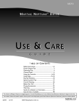
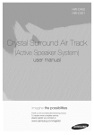
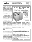
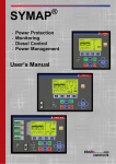
VCP SYSTEM Video Entertainment System BY R6400V © Copyright Rosen Products LLC 2000 All Rights Reserved Information in this document is subject to change without notice. Rosen Products LLC may have patents, patent applications, trademarks, copyrights or other intellectual property rights covering subject matter in this document. The furnishing of this document does not grant the use license to these patents, trademarks, copyrights, or other intellectual property. i 1-1 SAFE OPERATION Before You Drive What You Should Know About Having and Using the Auto Video Entertainment System in Your Vehicle The Auto VideoEntertainment System is The following guidelines will help you designed for rear passengers only. The driver operate your video entertainment system cannot safely view the FPD (flat panel safely and legally: display) while driving and should not attempt to do so. Many states have laws that restrict Never try to drive and view the screen. using a device in the vehicle that receives a Keep the back of the driver's seat forward of television broadcast. the screen. In most states it is unlawful for the FPD If you have a question, please call the Rosen screen to be visible to the driver, while other Tech Center at 1-888-883-2790. states have yet to address this issue. The screen can not be located at any point forward of the back of the driver's seat in: AL, AZ, CA, CO, LA, MA, MD, MN, NH, NC, OR, PA, SC, WA and WI. 1-2 DEPLOYMENT AND STOWING Depending on your type of vehicle, and the particular Auto Video™ System installed, the Auto Video™ screen will deploy and stow in one of the following ways: PUSH BUTTON PULL LATCH The push button on the overhead console releases Your system may have a pull latch located on the the Auto Video™ screen just far enough so that it bottom of the case. Pull latch down to deploy, the can easily be position for optimal viewing. This Auto Video™ screen automatically sends power to action sends power automatically to all the system all the system components. components. The screen will display the last video signal chosen. (see 2-6 configuring your system) 1-3 MANUAL CONTROLS The buttons located on the side of the screen perform many of the same functions as the system remote. By depressing any of these buttons once, the OSM displays the button’s function. Press again and the SPEAKERS VIDEO SOURCE CHANNEL DOWN CHANNEL UP function is carried out. CHANNEL UP/DOWN Scrolls up and down preset TV channels or scrolls up and down TV channels (see configuration settings). VIDEO SOURCE Selects video source TVVCPAUX SPEAKERS Selects audio on or off to the speakers of the vehicle sound system. Also, pressing and holding this button for 5 seconds will turn off the system. 1-4 Status Indicator Light The status indicator light is located on the right side face of the viewing panel just under the word "POWER". This indicator will display green when the vehicle’s key is turned on. This indicates that the system is ready for operation. The video entertainment system includes a temperature sensor. This sensor prevents the system from operating when the temperature inside the vehicle is too cold or too hot. The status LED will flash green under this condition. This is a normal feature of the system. As the interior of the vehicle warms up or cools down the LED will return to a constant green light and the system will be ready for operation. 1-5 Status LED REMOTE CONTROL AND OSM 2-2 System Remote Control 2-4 OSM (on-screen menus) 2-1 SYSTEM REMOTE The system remote control is the heart of your entertainment system. It controls the majority of your system’s functions. 1 LCD POWER MUTE MENU SCAN 2 AUDIO 3 DISPLAY 5 6 8 9 4 Video selection may be made by this remote control. The TV Tuner is accessed by remote for channel LOCK 7 selection and for fine tuning. ENTER When your system is equipped with a Rosen video VCP POWER AUTO 0 RECALL TV/AV cassette player, the VCP will operate using the same system remote control. TRACKING All OSMs (On-Screen Menus) are controlled by the system remote control. The system remote control is infrared and therefore System Remote must be aimed toward the flat panel display. 2-2 SYSTEM REMOTE CONTROL LCD POWER This button sends power to the flat panel display when pressed. It also turns off the power to the entire system. MUTE This button mutes audio to both the headphones and the factory sound system. AUDIO This button allows the sound of the video system to be heard through the vehicle speakers, the headphones, or both. DISPLAY This button removes the OSM from the flat panel display and brings the user back to the video source last selected. It will also display the TV channel while viewing the television. TV/AV This button selects the video source. TV VCP AUX The OSM displays the video sources as: TV # channel for television AV1 for video cassette player AV2 for the auxiliary video (see auxiliary equipment) MENU This button displays the OSM. (See section 2-4, On-Screen Menus) RECALL (Television function, see section 5-1) VCP POWER Turns VCP on and off. VCP Eject SCAN (Television function, see section 5-1) VCP Stop LOCK 2-3 VCP Fast Forward (Television function, see section 5-1) VCP Play AUTO - + VCP Rewind Tracking control of VCP II VCP Pause OSMs (ON-SCREEN MENUS) The engineering that went into the Auto Video OSM makes it very unique and easy to use. The following steps will guide you through the OSM. Pressing the MENU button on the system remote will display the OSM. When in the AV1 or AV2 selection and you press MENU, the display looks like the illustration at right: From here you can scroll the position arrow up and down using the and PICTURE AUDIO buttons on the remote. OPTIONS By pressing the ENTER button you can go to the next screen of the OMS for picture adjustment, MENU TO EXIT ENTER audio settings or options. The button will perform the same function as the ENTER button. (You may find using this button to be much easier and quicker since you will use it in many of the adjustments in the next menu.) 2-4 OSMs (ON-SCREEN MENUS) Selecting PICTURE will display this sub-menu. BRIGHTNESS You can scroll up or down to make your selection for COLOR adjustment. Brightness, color, tint and contrast are preset TINT at the factory. There is a "Restore to Factory" selection CONTRAST under OPTIONS which will restore the factory settings. ENTER MENU TO EXIT The PICTURE adjustments are displayed as follows: BRIGHTNESS 2-5 ENTER 32 COLOR ENTER 32 TINT 32 ENTER OSM (ON-SCREEN MENUS) By selecting AUDIO, you can change settings that configure the tuner and PICTURE initial speaker selection of your Auto Video system. AUDIO MODE - configures the tuner to receive STEREO or SAP (second AUDIO OPTIONS audio program) broadcasts. This setting effects all channels. NOTE: Configuring your system to SAP will effect ALL TV channels. If any of these channels do not broadcast audio using SAP, audio will not be present. ENTER MENU TO EXIT In this mode, SAP will be displayed with the channel number on the screen. SPK MODE (speaker mode) allows your to configure your Auto Video system to initialize with your individual preference of audio modes. LAST - System audio will be configured in the same mode as the system was previously operating. This setting allows audio through the factory sound AUDIO MODE: STEREO SPK MODE: LAST system or headphones, whichever was LAST set. ON - Sets the audio to play through the factory sound system every time the Auto Video system is turned on. (Tune to either 88.7 or 89.1 FM, depending on how your installer configured your system.) OFF - This selection will cause the audio to be heard only through the ENTER headphones when Auto Video system is turned on. MENU TO EXIT * To change the audio mode after the Auto Video system has been turned on, press the SPEAKER button located on the side of the display screen or press the AUDIO button on the remote control. 2-6 OSMs (ON-SCREEN MENUS) PICTURE AUDIO OPTIONS ENTER MENU TO EXIT CONFIGURE PWR MODE: PICTURE ENTER MENU TO EXIT STANDBY ENTER MENU TO EXIT Choosing OPTIONS - CONFIGURE provides setting that will configure the power mode. Your Auto Video system should be configured to the STANDBY powered mode. The STANDBY selection enables your Auto Video system components to be powered and available in a STANDBY mode when you turn the vehicle's ignition switch. To turn the Auto Video system on, press any (of the four) buttons located on the side of the display screen or press the LCD POWER button on the remote control. The LCD POWER button on the remote control will also turn the Auto Video system off. You should turn the Auto Video system off prior to stowing the system. When the Auto Video system is on, you can momentarily turn the ignition switch OFF and then to ACC without disrupting normal system operation. The Auto Video system will power down approximately six second after the ignition is switched off. 2-7 OSMs (ON-SCREEN MENUS) CONFIGURE PICTURE AUDIO OPTIONS SAVE USER RESTORE: PICTURE USER FACTORY ENTER MENU TO EXIT ENTER MENU TO EXIT ENTER MENU TO EXIT SAVE USER RESTORE: USER FACTORY ENTER MENU TO EXIT Selecting OPTIONS - PICTURE allows you to either save or restore the picture adjustments you have made. To save your settings, select SAVE USER and press ENTER. Now your brightness, color, tint and contrast are saved. Hint: This option works well for a night setting when you may want to reduce the brightness of the display. The factory settings are based on normal daytime viewing. By selecting RESTORE you can instantly retrieve the factory settings or your saved selections. 2-8 ROSEN VCPs 3-2 3-1 Operation and features of the Rosen RVP9800 video cassette player THE RVP9800 VCP To load a VHS tape into the VCP, gently insert the cassette, label-side up, into the cassette compartment until it stops. The VCP will continue loading the tape and begin playing it automatically. VIDEO CASSETTE PLAYER RVP9800R CST IN DEW L-HI-FI-R P/ STO T C EJE R PW A B C REW D Y PLA E FF F G H A. POWER button: Press this button to turn the VCP on or off. You can also use the remote control. C. STOP/EJECT button: Press this button once to stop and a second time to eject a cassette a cassette from the VCP. B. Stereo Hi-Fi L/R indicators: Both indicators glow when a Hi-Fi stereo video cassette is being played. D. REW button: Press this button to rewind the tape. You can view the tape while in the rewind mode as the tape plays. 3-2 ROSEN RVP9800 VCP E. PLAY button: Press this button to play a video tape. If a video tape is loaded, pressing this button will power the VCP. F. FF button: Press this button to fast forward the tape. You can view the tape in fast forward if the tape is playing. G. Cassette IN indicator: This indicator glows when there is a video cassette loaded in the VCP. 3-3 H. DEW indicator: When the indicator flashes, the Dew Sensor had been activated. When damaging-causing moisture condensation is detected within the VCP, the DEW Sensor circuit automatically prevents the VCP from accepting or playing tapes. When the dew sensor has been activated the DEW indicator will flash. To prevent damaging a video tape that is in the VCP when the indicator is flashing, press EJECT and remove the tape. Then, be sure the VCP is on so it can warm up and dry any accumulated moisture. When the DEW indicator stops flashing, the VCP will return to full operation. SYSTEM AUDIO 4-2 Wireless Headphones 4-3 Factory Sound System Adapter (System Audio Modulator) 4-1 WIRELESS HEADPHONES Using the wireless radio frequency (RF) headphones allows some passengers to listen to the Auto Videosystem while others can listen to the radio. To select the wireless headphones, be sure the on/off switch is in the ‘on’ position and the volume is turned all the way down. On/off and volume controls are located on the right ear piece of the headphones. The wireless headphones will work from any position inside the vehicle. The headphones are equipped with a fine tuning adjustment on the bottom of the left ear piece. Turn up the volume until you hear static or system sound. To tune out static or receive a stronger stereo signal use this adjustment. Once you have a good signal, turn the volume up to desired level. WARNING: To avoid potential damage to your hearing, always turn the headphone volume all the way down before placing them over your ears. Once they are on, adjust the volume to a comfortable level. 4-2 Figure 1. HEADPHONE BATTERIES: The battery compartment is located on the right ear piece. Replace with to "AAA" batteries when needed. See Figure 2-B Figure 2. FINE TUNING: Your RF headphones operate within a narrow radio frequency band and need to be adjusted when you first put them on. To do this there is a adjustment on the bottom of the left ear piece, turn the adjustment until the sound is clear and static free. See figure 2-H SYSTEM AUDIO MODULATOR When desired, Auto Video system sound can be enjoyed by all passengers in your vehicle through the factory radio sound system. Even though you cannot see the Rosen Audio Modulator because it is installed behind the dashboard, it enables the audio signal from the video source you select to work with your vehicle radio. Select the AUDIO button on the remote or the SPEAKER button on the LCD case. The monitor will display "SPEAKER ON". Then just tune to 88.7 FM to hear the sound and use the radio controls to adjust volume. You may want to preset one of your radio buttons to 88.7 FM to make operating the system quick and easy. You also are able to preselect what mode your system's audio will power up in. Refer to OMS 4-3 for configuring the audio of your system. 1 +12 VDC 100 mA 5 RIGHT RETURN 2 GND 6 LEFT AUDIO 3 LEFT RETURN 7 N/C 4 N/C 8 RIGHT AUDIO 8 NOTE: To avoid interference with other radio broadcast stations in your area, your installer may have chosen an alternate frequency of 89.1 FM for your system. Contact your installer/dealer for more information. 7 6 4 5 3 2 1 4-3 TV TUNER 5-2 TV Tuner OSM (On-Screen Menu) 5-6 TV Tuner Remote Control Functions 5-7 TV Antenna System 5-1 TV TUNER OSM Pressing the MENU button on the system will display the OSM. PICTURE If the system is in the TV mode and you press MENU, the display AUDIO looks like the diagram to the left. From here you can toggle the OPTIONS position arrow up and down using the TUNING remote. By pressing the ENTER button, you can go to the next buttons on the screen of the OSM for either picture adjustment, audio settings, ENTER MENU TO EXIT options, or tuning. Using the button in this stage will preform the same function as the ENTER button. (You may find using this button to be much easier and quicker since you will use it in many of the adjustments.) 5-2 TV TUNER OSM PICTURE CONFIGURE PWR MODE: INSTANT PICTURE AUDIO SCAN TYPE: OPTIONS TUNING ENTER MENU TO EXIT ENTER MENU TO EXIT RT SCAN ENTER MENU TO EXIT Choosing the OPTIONS menu (diagram 1, above) and moving into the CONFIGURE menu will allow you to set the SCAN TYPE to either RT SCAN (Real Time Scan), or PRE-SCAN. PWR MODE: INSTANT SCAN TYPE: PRE-SCAN ENTER MENU TO EXIT 5-3 RT SCAN sets the tuner to always scan to the next strongest signal when tuning up or down. This will come in handy when vehicle is in constant motion. PRESCAN will automatically scan through all 69 channels, lock and store the strongest signals. Once the PRESCAN cycle is complete, use the UP/DOWN to instantly scroll through the preset TV channels. The PRESCAN will take approximately 4 to 12 seconds depending on how many signals it finds. Refer to 5-5 "Lockout features" for locking out undesirable channels. TV TUNER OSM PICTURE AUDIO 00 00 ENTER ENTER SCAN AFC ON AFC ON OPTIONS TUNING ENTER SCAN MENU TO EXIT Choosing the TUNING menu will display the AFC (Automatic Fine Tuning Control) screen. In this buttons. You can fine tune only the particular TV channel that menu, you can fine tune with the you have selected on screen. The AFC will display OFF and a green indicator will appear and move right or left as you fine tune. The 00 display will monitor your movement. The number will increase (+) when moving to the right and decrease (-) when moving to the left. To hold the fine setting, press ENTER and the blue indicator will move on top of the green and the setting will be be saved. From this point, by using you can fine tune further with the green indicator. Pressing the SCAN button will allow the green indicator to use 00 as the starting point for additional fine tuning. To retain the fine tuned signal, push ENTER; your selection will be saved. You can then scroll up or down to the next channel and fine tune it. Pushing MENU twice or DISPLAY once will bring you out of the fine tuning menu. Anytime the tuner goes through the SCAN function, all fine tuning is reset. (See 5-5 for SCAN) 5-4 TV TUNER REMOTE CONTROL FUNCTIONS The system remote control is the main control for the television tuner. 1 LCD POWER MUTE MENU SCAN 2 AUDIO 3 DISPLAY 5 6 8 9 Other than the two manual controls on the display for channel up and 4 down, all other tuner functions are controlled by the system remote LOCK control. This section of the manual will explain the tuner control buttons. LOCK 7 ENTER This button performs a unique function that is found VCP POWER only on the Auto Video system. Pressing it will lock out AUTO 0 RECALL undesirable channels that the tuner may have selected even though the reception is weak. LOCK allows you TRACKING to skip them. When you press the LOCK button, a blue screen will appear and CHANNEL XX LOCKED will be displayed. selection. To unlock a channel, use the up/down channel selector appear in sequence during the up/down scan Once the undesirable channels are locked, they will not to select the channel and press LOCK again. To unlock all channels, push the SCAN button. 5-5 System Remote TV/AV TV TUNER REMOTE CONTROL FUNCTIONS SCAN While in TV tuner mode and with the system configured to PRE-SCAN, this button will scan through all 69 channels and preset the strongest channels to memory. When the system is con-figuring to RT SCAN, this button will unlock all channels. (See 5-3 for SCAN TYPE) NUMBERS There are 10 selections on the remote with blue numbers located on the top right corner of the buttons. These are direct access channel entry buttons. They allow you to access a numbered channel directly instead of using the up and down buttons. To use these, press the ENTER button first. A blue screen will be displayed with the words ENTER CHANNEL NUMBER followed by the number 0 ...9. When this screen appears, enter the desired channel number with two digits. (example: channel twelve is 12 and channel two is 02. 5-6 TV TUNER REMOTE CONTROL FUNCTIONS DISPLAY During the tuner mode, this button when pressed will display the TV channel while viewing the television. It will also exit the user out of the fine tuning OSM. RECALL The RECALL button should be thought of as a recall/memory button and not last display channel recall. It will allow the toggling back and forth between two stored channels. When one of the desired channels is displayed on the panel, press RECALL. The channel will be saved and another channel will appear. Channel surf until the second desired channel is displayed and press RECALL again. Now when you press RECALL, you will be able to switch back and forth between the two selections. 5-7 OPTIONAL EQUIPMENT 6-2 Connections for Game Systems and Camcorders 6-3 AC Power Inverter 6-4 Additional Headphones 6-1 CONNECTING GAME SYSTEMS OR CAMCORDERS P VC er Pow D LC itor n Mo Mo dula tor eadp H hon Connecting game systems or camcorders is as easy as matching the colors of the RCA plugs on the device to the colors on the INPUT jacks on the TV Tuner Interface. Yellow -> Yellow (Video) White -> White (Left Audio) Red -> Red (Right Audio) in Ma er Pow es te An R t tpu Ou L ce rfa 000 Inte Rev er 102 Tun 103-0 TV odel 8 nna V t tpu Ou M Inp V R ut L ut Inp sen Ro CP V Red Yellow White With some games systems, an adapter is required. These adapters are usually available from the game system supplier. Contact your local Auto Video retail outlet when you need assistance. 6-2 AC POWER INVERTERS Power Inverter Some video game systems, camcorders, and other video devices require 120 VAC "household" current instead of the 12 VDC supplied by your vehicle. These devices require the use of an AC power inverter (not a converter) to change the vehicle’s 12 VDC to 120 VAC. Inverters usually plug into the vehicle's cigarette lighter or 12 VDC power point and the video device plugs into them. It is absolutely essential that the inverter be rated to supply AC power equal to or greater than the power requirement (in watts) of the video device. (See specification below.) These power inverters are available from your dealer/installer. Specification: Most game systems require an inverter supplying a minimum of 140 watts output 6-3 ADDITIONAL HEADPHONES Additional sets of wireless headphones are available by contacting your dealer/installer or by calling Rosen Products at 1 (800) 284-7677. 6-4 INDEX P F A AC power inverters Purchasing Connecting Additional headphones Audio on/off AUDIO mode Audio Modulator Configuring Description Frequencies Selecting Auto Tracking AV1 / AV2 selection 6-2 6-2 6-3 1-4, 2-3, 2-6 2-6 4-3 4-3 4-3 4-3 2-3 2-4 B Brightness 2-5 Fine tuning Flat panel H 1-4, 5-5 2-5 2-6 2-5 D Deployment and storage 1-3 ENTER command 2-8 E Headphones Selecting/Tuning 4-2 Infrared INSTANT function- 2-2 2-7 LAST function LOCK function 2-6 2-3 I 1-4 2-3, 2-4 2-3 OSM 1-4 2-2 2-3 2-7 2-4 1-5 2-7 RECALL functionRemote control DescriptionFeaturesRESTORE function- 2-3 Safe operationSAPSAVE USER functionSCAN functionSpeaker selectionSPEAKER mode STANDBY function STATUS INDICATOR LED StereoStowing O Location Remote control Clearing CONFIGURE function DescriptionOPERATING TEMPERATUREOPTIONS function 2-4, 2-6 2-8 2-3 2-7 1-4 2-2 2-3 2-8 S M Manual controls Location MENU function MUTE function Picture adjustment PICTURE function PowerPOWER modePreset channel R L C Channel SelectionColor adjustment Configuring your system Contrast adjustment 2-2 1-2, 2-2 1-2 2-6 2-8 2-3, 5,6 2-3 1-4, 2-3, 2-6 2-7 1-5 2-6 1-3 T Technical helpTint adjustmentTV / AV selection 1-2 2-5 2-3 7-1 INDEX V T (con't) TV tuner Remote control SCAN LOCK DISPLAY DIRECT CHANNEL ENTRY TV tuner OSM AFC control AUDIO function CONFIGURE function OPTIONS function PICTURE function POWER mode SAP/STEREO SCAN TYPE function RT scan Pre-scan - 7-2 2-2 5-6 5-6 5-7 5-6 5-4 2-6 5-3 2-6, 5-3 2-4, 2-6, 2-8 2-7 2-6 5-3 5-3 5-3 W VCP controls VCP face controls CASSETTE IN DEW FAST FORWARD PLAY POWER REWIND STOP / EJECT VCP power on / off Video Cassette Player (VCP) Video Source Selection 2-3 3-3 3-3 3-3 3-3 3-2 3-2 3-2 2-3 2-2 1-4 Wireless headphones Battery installation/removal On / off switch 4-2 4-2 All information, including illustration, is believed to be reliable. Users, however, should independently evaluate the suitability of each product for their application. Rosen makes no warranties as to the accuracy or completeness of the information, and disclaims any liability regarding its use or installation. Rosen's only obligations are those in the Rosen Standard Terms and Conditions of Sale for this product, and in no case will Rosen be liable for any incidental, indirect or consequential damages arising from the sale, resale, use or misuse of the product. Specifications are subject to change without notice. Rosen reserves the right to make changes without notification to Buyer - to materials or processing that do not affect compliance with any applicable specification. E N T E R TA I N M E N T S Y S T E M S BY Manual Part Number 9100-0102-807