1
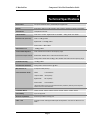
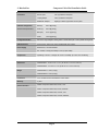
VideoEase™ Component Video Hub
(500250, 500251, 500252, 500253)
Installation Guide
P/N: 94-000382-B, SE-000581-B
© MuxLab Inc.
Component Video Hub Installation Guide
Copyright Notice :
Copyright © 2006-2007 MuxLab Inc. All rights reserved.
Printed in Canada. No part of this publication may be reproduced, stored in a retrieval
system, or transmitted in any form or by any means, electronic, mechanical,
photocopying, recording, or otherwise without prior written permission of the author.
Trademarks :
MuxLab and VideoEase are registered trademarks of MuxLab Inc.
Page 2
© MuxLab Inc.
Component Video Hub Installation Guide
Table of Contents
1. Overview ........................................................................................................................4
1.1. Description........................................................................................................4
1.2. Features.............................................................................................................4
2. Technical Specifications ...............................................................................................5
3. Installation Procedure ..................................................................................................7
3.1. Parts List ...........................................................................................................7
3.2. Product Overview .............................................................................................7
3.3. Pre-Installation Checklist..................................................................................8
3.4. Physical Installation ..........................................................................................8
3.5. Installation Procedure .......................................................................................9
3.6. Cascading........................................................................................................13
4. Troubleshooting ..........................................................................................................15
5. Product Warranty Policy ...........................................................................................17
Page 3
© MuxLab Inc.
Component Video Hub Installation Guide
1.
Overview
1.1.
Description
The VideoEase Component Video Hub allows one (1) full component video
(YPbPr/RGB) source and one (1) digital or analog audio video source to be
distributed up to eight (8) or sixteen (16) destinations depending on the model
for more cost-efficient cabling. The 500250 supports up to eight (8) ports.
The 500252 supports up to sixteen (16) ports. Applications include; Digital
signage, Boardroom systems, Multi-room systems, Classroom training, Retail
systems.
1.2.
Features
•
Modular RJ45 on input and output
•
Cascadable up to two (2) levels with other hubs
•
Supports 480i/p up to 1,000 ft (305m) via Cat5
•
Supports 720p/1080i/p up to 500 ft (152m) via Cat5
•
Supports digital or analog audio on fourth twisted pair
•
Configuration switch to support digital audio or analog audio
•
Ground loop isolation on every port
•
Integrates seamlessly with MuxLab component video baluns
Page 4
© MuxLab Inc.
Component Video Hub Installation Guide
2.
Technical Specifications
Environment
Component baseband video (YPbPr/RGB) and Digital Audio
Devices
DVD players, DVR, AV matrix switchers, DLP projectors, plasmas, monitors, home theatre.
Transmission
Transparent to the user.
3 dB Bandwidth
Video: DC to 77 MHz. Digital Audio: DC to 52MHz
Insertion Loss (differential)
Video: -0.8 dB @ 4 MHz
Analog Audio: 20 to 20kHz
Digital Audio: -1.26 dB @ 4 MHz.
Analog Audio: 1 dB @ 4 MHz.
Video Return Loss
-23dB @ 4 MHz.
Common Mode Rejection
Video: Greater than 40 dB over the frequency range.
Input: balanced. Output: balanced
Digital Audio: Greater than 31.5 dB over the frequency range
Analog Audio: Greater than 60 dB @ 1 KHz; Greater than 40 dB over the frequency range.
Crosstalk Immunity
-60 dB @ 4 MHz
Total Harmonic Distortion
Analog Audio: Less than 0.007% @ 1KHz.
Max. Distance via
Component Video (YPbPr):
Cat 5 Twisted Pair (UTP)*
480i/p:
1,000 ft (305m) *
720p and 1080i:
500 ft (152m) *
Digital Audio:
600 ft (182m) *
Analog Audio:
3.250 ft (990m) *
*Measured between Source (ie;DVD) and Destination (ie;Monitor) with Hub placed anywhere
between the source and destination
Compatible Baluns
500000, 500002, 500009, 500020, 5000021, 500050, 500051, 500052, 500053
Cascadability
Up to two (2) levels.
Ground Loop Isolation
Ground loop isolation on every port.
Cable – UTP
24 gauge or lower solid copper twisted pair wire impedance: 100 ohms at 1 MHz. Cat 3 or
better.
Page 5
© MuxLab Inc.
Connectors
Component Video Hub Installation Guide
Source Input:
One (1) RJ45S on rear panel
Looping Output:
One (1) RJ45S on rear panel
Distribution Outputs:
Eight (8) or sixteen (16) RJ45S on front panel
RJ45 Pin Configuration
Red (Pr) :
Pins 7 [R] & 8 [T]
Reverse Polarity Sensitive
Green (Y) :
Pins 3 [R] & 6 [T]
Blue (Pb) :
Pins 1 [R] & 2 [T]
Audio :
Pins 4 [R] & 5 [T]
Configuration Switch
Sets hub to support digital or analog audio on fourth twisted pair. Factory default: analog audio.
LED Diagnostics
Power (green), Video Sync (green), Digital Audio Sync (green):
Power Supply
External AC: 110V and 220/240V
DC: 12VDC, 1.25A (8-port model) or 2.5A (16-port model).
Temperature
Operating: 0º to 40º C. Storage:-20º to 85º C. Humidity: up to 95% non-condensing.
Dimensions
500250/500251: 9.125” x 6.75” x 1.75” (23.18 cm x 17.15 cm x 4.45 cm)
500252/500253: 19” x 6.75” x 1.75” (48.26 cm x 17.15 cm x 4.45 cm)
Weight
500250/500251: 3.3 lbs (1.5 kgs)
500252/500253: 5.5 lbs (2.5 kgs)
Compliance
FCC, CE-EMC Directive 89/336/EEC, RoHS, WEEE
Warranty
2 years
Order Information
500250 Component Video Hub, 8 Ports, 110V
500251 Component Video Hub, 8 Ports, 220/240V
500252 Component Video Hub, 16 Ports, 110V
500253 Component Video Hub, 16 Ports, 220/240V
Page 6
© MuxLab Inc.
Component Video Hub Installation Guide
3.
Installation Procedure
3.1.
Parts List
The Component Video Hub comes with the following parts. Please verify that
all pieces are present before proceeding.
3.2.
•
Base Unit
•
External Power Supply 12VDC/1.25A (500250, 500251) or
12VDC/2.5A (500252, 500253)
•
Rubber stand-offs (500250, 500251 only)
•
Installation Guide
Product Overview
The external connections and diagnostics of Component Video Hub are
detailed in the following diagrams. Please familiarize yourself with them
before installing the unit.
Component Video Hub
PWR
Video
Digital
Audio
Figure 1: Component Video Hub 8 Ports (500250, 500251) Front panel
Component Video Hub
PWR
Video
Digital
Audio
Figure 2: Component Video Hub 16 Ports (500252, 500253) Front panel
Input
Power
12VDC
1.25A
Analog Digital
Audio Audio
RJ45 Pin Configuration
Green (Y)
3 [R] &
Blue (Pb)
1 [R] &
Red (Pr)
7 [R] &
Audio
4 [R] &
Cascade
Output
6
2
8
5
[T]
[T]
[T]
[T]
Figure 3: Component Video Hub Rear panel (all models)
Page 7
© MuxLab Inc.
3.3.
Component Video Hub Installation Guide
Pre-Installation Checklist
The Component Video Hub provides a centralized component video
distribution center via copper twisted pair cabling.
1. The Component Video Hub is typically installed in a remote telecom room
and is connected to the component video source and display devices via
Cat5 twisted pair. MuxLab component video baluns are installed at each
component video devices to support the connection to the hub via Cat5
cable.
2. For optimum performance and to support HDTV (720p, 1080i/p)
resolution, the Component Video Hub is used in conjunction with
MuxLab’s passive Component Video Baluns (p/ns 500050, 500051,
500052, 500053).
3. The Component Video Hub will also work with third party vendor baluns,
providing the pin configuration and signal polarity are compatible.
However, performance specifications may be affected.
3.4.
Physical Installation
The Component Video Hub has two models; 8-port desktop (500250, 500251)
and 16-port rack-mount (500252, 500253).
1.
If the 8-port hub is being installed on a desk, select the final destination for
the product and install the unit on a desk or shelf as shown below.
Figure 5: 8-port desktop installation
2.
If the 16-port hub is being installed, select the final destination for the
product and install the unit using standard rack-mount screws.
Page 8
© MuxLab Inc.
Component Video Hub Installation Guide
Figure 6: 16-port rack-mount installation
3.5.
Installation Procedure
The Component Video Hub is available in 8-port (500250, 500251) and
16-port (500252, 500253) versions. In order to install the product, please
follow the steps below:
1. Install the Component Video Hub in its final location by performing steps 1
or 2 listed in the previous section.
2. Ensure that the power is turned off on the component video source and
displays.
3. If audio will be transmitted along with video, set the hub to digital or
analog audio by sliding the switch on the rear panel to the appropriate
position as shown in the diagram below. The factory default setting is
“analog audio”.
4. In order to distribute component video (YPbPr/RGB) and audio (optional),
one (1) Component Video Balun must be connected at the component
video source and at each component video display. To install the baluns,
perform the following steps (5, 6 and 7):
5. Identify the pin configuration of the baluns. Three (3) twisted pairs are
required for video and one (1) twisted pair is required for optional digital
audio. The pin configuration follows the EIA/TIA 568A/B standard. The
Component Video Baluns are reverse polarity sensitive. Please ensure that
wiring is straight-through (Ring to Ring, Tip to Tip).
6. Plug one (1) Component Video/Digital Audio Balun (500050, 500051) or
Component Video/Analog Audio Balun (500052, 500053) into the
Page 9
© MuxLab Inc.
Component Video Hub Installation Guide
component video coaxial cable output of the video source according to the
color code of the RCA cable leads.
7. Connect a Component Video/Digital Audio Balun (500050, 500051) or
Component Video/Analog Audio Balun (500052, 500053) to each
component video display.
8. Complete the connection between the component video source and the
Component Video Hub using standard straight-thru Cat5 twisted pair cable
and connecting hardware, terminated on RJ45 plugs at both ends. Ensure
that there are no split pairs or taps.
9. Complete the connection between the hub and each component video
display using standard straight-thru Cat5 twisted pair cable and connecting
hardware, terminated on RJ45 plugs at both ends. Ensure that there are no
split pairs or taps.
10. If audio is to be connected (optional), connect an RCA lead between each
Component Video Balun and the audio equipment at both ends.
11. Connect the external 12VDC power supply to the hub and plug the power
supply into an AC power outlet. If power is present, then the green power
LED will be ON.
12. Power-on the component video equipment. Check the image quality and
refer to the troubleshooting table below if the image quality is
unsatisfactory.
Page 10
© MuxLab Inc.
Component Video Hub Installation Guide
13. The following diagrams show a couple of typical configurations.
Figure 4: Typical Configuration – Component Video and Digital Audio
Figure 5: Typical Configuration – Component Video and Digital Audio
Page 11
© MuxLab Inc.
Component Video Hub Installation Guide
Figure 6: Typical Configuration – Component Video and Analog Audio
Page 12
© MuxLab Inc.
3.6.
Component Video Hub Installation Guide
Cascading
In order to drive more displays, the Component Video Hub may be cascaded with another
hub. In order to optimize the image quality, it is recommended to cascade up to two (2)
levels only as shown in the following diagrams.
Figure 6: Cascading one hub
Figure 7: Cascading Multiple Hubs
Page 13
© MuxLab Inc.
Component Video Hub Installation Guide
In order to cascade two hubs together, connect a Cat5 straight-through cable between the
Output Port (regular or cascade) of the source hub to the Input Port of the second hub as
shown in the following diagram.
Figure 8: Cascade Hub Cabling
Page 14
© MuxLab Inc.
Component Video Hub Installation Guide
4.
Troubleshooting
The following tables describe some of the symptoms, probable causes and possible
solutions in respect to the installation of the Component Video Hub. If you still cannot
diagnose the problem, please call MuxLab Customer Technical Support at 877-689-5228
(toll-free in North America) or (+1) 514-905-0588 (International).
Video
Power
LED
Video
LED
Probable Causes
Possible Solutions
No image
OFF
OFF
Power off.
Check power supplies of Component
Video equipment.
No image
ON
ON
Wrong pin configuration.
Check pin configuration and verify
straight-thru wiring.
No image
ON
OFF
No continuity in video link.
Verify cable continuity between pairs of
baluns.
No image
ON
ON
Improper connection. Swapped pairs.
Check that baluns are connected to
correct video inputs and outputs.
Picture
distorted
ON
ON
EMI interference.
Check that wiring is not too close to
transformers and lighting ballasts.
Split pair.
Check if the UTP pairs are not split.
Wrong
colors
ON
ON
Reversed polarity.
Check wiring and ensure straight-through
polarity.
Loss of
brightness
ON
ON
Exceeded distance/bandwidth
specifications.
Check DC loop resistance and verify if
distance spec is exceeded.
Lower grade UTP cable is introducing
high losses.
Reduce cable length or eliminate highloss components.
Loss of
color
Smearing
Horizontal
upward
moving
bands
Replace cable by higher grade.
ON
ON
Ground loop problem between one or
more devices.
Page 15
Consecutively turn off other video
sources to determine which video source
is the cause of interference. Install RGB
ground loop blockers at the source or
displays.
© MuxLab Inc.
Component Video Hub Installation Guide
Digital Audio
Digital
Audio LED
Probable Causes
Possible Solutions
No audio
OFF
Power off.
Check power supplies of the audio
equipment.
No audio
ON
Wrong pin configuration.
Check pin configuration and verify straightthru wiring.
No audio
ON
No continuity in video link.
Verify cable continuity between pairs of
baluns.
No audio
ON
Improper connection Swapped
pairs.
Check that baluns are connected to correct
video inputs and outputs.
Missing
channels
ON
Cabling problem between the
decoder/amp and the audio
speakers.
Check audio speaker cabling.
Noise, static
ON
EMI interference.
Check that wiring is not too close to
transformers and ballasts.
Noise, static
ON
Distance exceeded or unusual cable
attenuation.
Check cable distance and cable grade.
When contacting your nearest MuxLab dealer or MuxLab Technical Support please have
the following information ready:
•
Unit model number.
•
Cabling lay-out. Include model of
component video source and
receiver, cable length and type.
•
Description of problem.
•
Page 16
List of tests performed.
© MuxLab Inc.
Component Video Hub Installation Guide
5.
Product Warranty Policy
Items under warranty - Company Policy
MuxLab guarantees its products to be free of defects in manufacturing and workmanship for the warranty period from the date
of purchase. If this product fails to give satisfactory performance during this warranty period, MuxLab will either repair or
replace this product at no additional charge, except as set forth below. Repair and replacement parts will be furnished on an
exchange basis and will be either reconditioned or new. All replaced parts and products become the property of MuxLab. This
limited warranty does not include repair services for damage to the product resulting from accident, disaster, misuse, abuse, or
unauthorized modifications or normal decay of battery driven devices. Batteries if included with the product are not covered
under this warranty.
Limited warranty service can be obtained by delivering the product during the warranty period to the authorized MuxLab dealer
from whom you purchased the product, or by sending it to MuxLab. MuxLab will not accept any such product for repair
without a Return Material Authorization number (RMA#) issued by its Customer Service Department and a proof of purchase
date. If this product is delivered to MuxLab by mail, you agree to assume risk of loss or damage in transit, to prepay shipping
charges to the warranty service location, and to use the original shipping container or equivalent.
THE ABOVE LIMITED WARRANTY IS THE ONLY WARRANTY COVERING YOUR MUXLAB PRODUCT. THERE
ARE NO OTHER WARRANTIES, EXPRESSED OR IMPLIED, INCLUDING WARRANTIES OF MERCHANTABILITY OR
FITNESS FOR A PARTICULAR PURPOSE. SOME STATES DO NOT ALLOW LIMITATIONS ON IMPLIED
WARRANTIES, SO THE ABOVE LIMITATION MAY NOT APPLY TO YOU.
IF THIS PRODUCT IS NOT IN GOOD WORKING ORDER, YOUR SOLE REMEDY SHALL BE REPAIR OR
REPLACEMENT AS PROVIDED FOR ABOVE. IN NO EVENT SHALL MuxLab BE LIABLE TO YOU FOR ANY
DAMAGES, INCLUDING ANY LOSS OF PROFITS, LOST SAVINGS, OR OTHER INCIDENTAL OR CONSEQUENTIAL
DAMAGES ARISING OUT OF THE USE OF OR INABILITY TO USE THIS PRODUCT, EVEN IF MUXLAB OR AN
AUTHORISED MuxLab DEALER HAS BEEN ADVISED OF THE POSSIBILITY OF SUCH DAMAGES; NOR WILL
MUXLAB BE LIABLE FOR ANY CLAIM BY ANY OTHER PARTY. SOME STATES DO NOT ALLOW THE
EXCLUSION OR LIMITATION OF INCIDENTAL OR CONSEQUENTIAL DAMAGES FOR CONSUMER PRODUCTS, SO
THE ABOVE LIMITATIONS OR EXCLUSIONS MAY NOT APPLY TO YOU. THIS WARRANTY GIVES YOU SPECIFIC
LEGAL RIGHTS. YOU MAY ALSO HAVE OTHER RIGHTS WHICH MAY VARY FROM STATE TO STATE.
Warranty Periods
Any product found to be defective within three (3) months of invoice, including one (1) month shelf life, may be returned for
replacement by a new unit or a satisfactory repair within one (1) month of receiving any returned product. The customer must
provide MuxLab with the serial number and proof of purchase of the defective unit being returned. All R.M.A.’s issued are
subject to inspection by MuxLab, and will be returned to customer if not properly package – units must be returned in original
container or equivalent. MuxLab will not accept any such product for repair without an authorization for its Technical
Support department and without a return authorization number issued by MuxLab Customer Service department. For credit
& replace R.M.A., customer will be liable to pay replacement invoice if defective products are not returned.
Product more than six months old, including shelf life.
The defective unit must be returned prepaid to MuxLab and then the unit will be repaired or if repair is not possible, replaced by
an equivalent unit and returned to the customer within one (1) month of receiving any returned product. There is no charge for
repair (parts and labor) during the full warranty period.
Items Defective and not under Warranty
For products which are no longer under warranty the policy is repair and return. An amount of 25% of the products
published list price at the time of purchase will be charged. Customer must issue a purchase order to cover the cost of repair.
Each unit will be returned to the customer within one (1) month from receipt of the unit by MuxLab. The defective unit must
be returned prepaid to MuxLab. The repaired unit will be returned to the customer FOB MuxLab. The repaired unit has a 90
day warranty.
Page 17
© MuxLab Inc.
Component Video Hub Installation Guide
Page 18
© MuxLab Inc.
Component Video Hub Installation Guide
Page 19
© MuxLab Inc.
Component Video Hub Installation Guide
Page 20
© MuxLab Inc.
Component Video Hub Installation Guide
MuxLab Inc.
8114 Trans Canada Hwy, St. Laurent,
Quebec, Canada, H4S 1M5
Tel.: +1 (514) 905-0588 Fax: +1 (514) 905-0589
Toll Free (North America): 877 689-5228
URL: www.muxlab.com
E-mail: [email protected]
Page 21