1
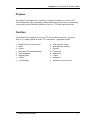
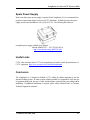
LongReach 16 Active CCTV Receiver Hub
LongReach 16 Active CCTV Receiver Hub
(500120, 500121, 500122, 500123)
Application Guide
Version 1.03
April 2006
© MuxLab Inc.2004-2006
1
LongReach 16 Active CCTV Receiver Hub
Purpose
The purpose of this document is to explain how to apply the LongReach 16 Active CCTV
Receiver Hub under different operating conditions and to discuss issues that are not necessarily
covered in the product Datasheet, Installation Guide or CCTV Balun Application Guide.
Function
The function of the LongReach 16 Active CCTV Receiver Hub is to provide a “plug-and
forget” Cat 5 cabling solution for in the CCTV environment. Applications include:
•
•
•
•
•
•
•
•
Industrial and Corporate Security
Banks
Schools
Prison and Correctional Institutions
Traffic Monitoring
Shopping Malls
Airports
Car dealerships
© MuxLab Inc.2004-2006
•
•
•
•
•
•
•
•
Parks and pubic venues
Manufacturing complexes
Hospitals
Government
Retail stores
Casinos
Parking lots
Underwater camera systems
2
LongReach 16 Active CCTV Receiver Hub
Automatic Image Adjustment (AGC)
The LongReach 16 has auto-gain control (AGC) that automatically optimizes the video output
signal according to the cable length and other factors that affect signal transmission such as
temperature and cable grade. The AGC optimizes the brightness and sharpness levels of the
video signal so that the image is as good as if the adjustments were performed manually. As
cable length increase, AGC compensation increases as illustrated below.
AGC
Brightness
Sharpness
Cable length
Due to the real time processing of the signal, there is brief time delay before the image is
stabilizes. This may take a two to five seconds. Once the image has stabilized it remains locked
to that setting even if the camera is disconnected from the CCTV hub as shown in the following
diagram.
AGC
Optimum Brightness
Optimum Sharpness
Time
However, if the hub is powered off and on, or a hub port is connected to a different camera,
then the AGC will readjust again. AGC re-adjusts when the signal input levels and/or cable
length changes.
© MuxLab Inc.2004-2006
3
LongReach 16 Active CCTV Receiver Hub
Adding Cameras in an Existing Hub Installation
In an existing installation, it may be necessary to add or change cameras on a LongReach 16
Hub. In order to ensure proper functioning of the hub after the new cameras are connected, it is
necessary to first “reset” the hub before bringing the new cameras on-line. This may be
achieved by performing one of the following procedures:
Procedure A:
1. Connect the new cameras to the hub while the hub is powered on.
2. Power off the hub for one minute in order to allow the hub to reset.
3. Power on the hub and allow one (1) minute for the auto-gain to stabilize.
Procedure B:
1. Power off the hub.
2. Connect the new cameras to the hub while the hub is powered off.
3. Power on the hub and allow one (1) minute for the auto-gain to stabilize.
Please note that if the above procedure is not followed, then the hub may not properly perform
auto-gain compensation resulting in poor image quality.
Switching Camera Connections
Each port on the LongReach 16 is independently controlled and optimized for the camera and
cable that is connected to it. When a LongReach port is switched to a different camera, either
manually or via a video cross-point switch, the AGC control for that port will automatically
recalculate the optimum settings. This may take up to two or three seconds. The greater the
difference in cable length or signal level between the first camera and the second camera, the
greater will be AGC time delay. When the cable length and signal input level of the switched
ports are similar, the time delay for the image to stabilize will be minimal. Therefore the time
necessary for AGC compensation to stabilize is related to the change in cable length and/or
input signal levels.
© MuxLab Inc.2004-2006
4
LongReach 16 Active CCTV Receiver Hub
Cabling Topologies
The LongReach 16 may be deployed in various cabling topologies depending on the type of
CCTV system and the architectural layout of the site. There are three basic layouts shown in
the following diagrams.
Camera to Head End – Short Distance
In this scenario, the LongReach 16, central monitoring equipment and remote power are all colocated.
In regard to the cabling, siamese cables for video, power and control may be installed between
the central monitoring room. Alternatively, Cat5 cables may be used to transport video, power
and control to the camera. It is important to note that if remote power is transmitted via Cat5
cable, a Class II power supply must be used.
Camera to Head End – Extended Distance
In this layout the LongReach 16 and the central monitoring equipment are co-located and due
the distance, remote power to the camera is supplied locally.
© MuxLab Inc.2004-2006
5
LongReach 16 Active CCTV Receiver Hub
Camera to Remote Telecom Room – Extended Distance
In some installations, it is more practical to install the cabling hardware in a remote telecom
room and insert remote power and control if necessary at this point. Here too, siamese cables
may be used between the telecom room and the cameras. Alternatively, Category 5 cables
may be used to carry all three signals. A Cat5 “110” style patch panel may be used to
concentrate all three signals over one Cat5 cable. It is important to note that if remote power is
transmitted via Cat5 cable, a Class II power supply must be used.
© MuxLab Inc.2004-2006
6
LongReach 16 Active CCTV Receiver Hub
Integration into a Structured Cabling System
One of the benefits of the LongReach 16 - Model 500120 is its ability to integrate easily into a
structured cabling system. In this scenario CCTV baluns convert all CCTV equipment ports to
twisted pair and then Category 5 interconnect hardware can be used to manage the physical
camera connections without the need to install additional costly and bulky coaxial cable. The
following diagram shows a typical configuration where the CCTV Hub is installed in a remote
equipment or telecom room away from the central monitoring equipment.
© MuxLab Inc.2004-2006
7
LongReach 16 Active CCTV Receiver Hub
The hub may be installed up to 500 ft from the receiver (DVR, mux), thereby allowing the hub
to be installed in a remote wiring or equipment room for greater cabling flexibility. The following
diagram shows how the hub works in conjunction with a “110” patch panel system. The patch
panel features RJ45 modular jacks in front and “110” style punchdown connectors on the rear
panel.
The camera inputs arrive at the RJ45 side of the patch panel. On the rear panel, the individual
twisted pairs from the CCTV hub are terminated on punch down connectors. Remote power
and/or PTZ control may be inserted into the Cat5 cable at the “110” panel. From the CCTV
hub, bulk Cat5 cables transmit the camera signals to the DVR or mux where they terminate on
CCTV Screw Terminal Baluns (500009).
© MuxLab Inc.2004-2006
8
LongReach 16 Active CCTV Receiver Hub
The following diagram shows how remote power and PTZ control may be inserted at a “110”
style punch-down block. A similar procedure could be used for 66, BIX and Krone
interconnect hardware. The diagram shows MuxLab’s recommended convention to work in
conjunction with the CCTV Pass-Thru Balun (500022).
Pair 1
Blue
Pair 2
Pair 3
Pair 4
Orange
Green
Brown
White solid/Brown band Video (T)
Brown solid/White band Video (R)
White solid/Green band Power (Red wire)
Green solid/White band Power (Black wire)
White solid/Orange band Power (Red wire)
Orange solid/White band Power (Black wire)
White solid/Blue band Control +
Blue solid/White band Control -
At the camera end, Cat5 4-pair cables carry video and/or power and control to each camera.
If only video is required, the connections terminate on the CCTV Modular Balun (500000),
CCTV Screw Terminal Balun (500009) or CCTV Mini Balun (500023) as shown below.
© MuxLab Inc.2004-2006
9
LongReach 16 Active CCTV Receiver Hub
Some CCTV systems integrators are specifying that remote power, PTZ control and video be
transmitted via one 4-pair Cat5 cable. In this application, the Cat5 cable may be terminated on
the CCTV Pass-Thru Balun. In order to determine the maximum distances for remote power,
please refer to the CCTV Balun Application Guide available in pdf format at
http://www.muxlab.com/assets/files/application_guides/VE_CCTV_Balun.pdf, or download the
MuxLab Distance Calculator (20MB) by clicking on the following link:
http://www.muxlab.com/assets/files/application_notes/DistanceCalculator.zip
The RJ45 pin configuration of the CCTV Pass-Thru Balun (500022) follows the EIA/TIA
568B standard as shown in the following diagram and is compatible with the wiring described
above for the hub.
Pair 3
White solid/Blue band Control +
Blue solid/White band Control Orange solid/White band Power (Black wire)
White solid/Orange band Power (Red wire)
White solid/Green band Power (Red wire)
Green solid/White band Power (Black wire)
Pair 1
Pair 2
Pair 4
White solid/Brown band Video (T)
Brown solid/White band Video (R)
12345678
CCTV Pass-Thru Balun (500022)
RJ45 Jack EIA/TIA 568B
© MuxLab Inc.2004-2006
10
LongReach 16 Active CCTV Receiver Hub
Terminating on Coaxial Cable at the DVR
If the LongReach 16 is installed near the DVR or mux and coaxial cable is preferred, the
500122 may be used for this application. The 500122 are fitted with BNC output for this
purpose.
© MuxLab Inc.2004-2006
11
LongReach 16 Active CCTV Receiver Hub
Large Installations
In large installations that have hundreds or thousands of cameras, it is often necessary to allow
many security personnel to access each camera in full-motion video on demand. This usually
requires an analog video cross-point matrix switch that is in turn connected to several analog
video monitors as well as to digital video storage hardware. The following diagram illustrates
the use of the LongReach 16 in such a configuration.
In the above configuration, the UTP/UTP version (500120) is used in conjunction with the
CCTV Screw Terminal Balun (500009) to provide a total UTP cabling solution between the
matrix switch and the cameras.
© MuxLab Inc.2004-2006
12
LongReach 16 Active CCTV Receiver Hub
Relocation of DVR Head-end
In some older installations, it is necessary to relocate the DVR head end while preserving the
original camera cabling intact. In the original installation, coax cables were fed to a DVR room.
The DVR equipment was subsequently moved to a new location further away and new Cat5
cabling was installed. MuxLab’s Passive CCTV Hub (500130) may be used to convert the
original sixteen (16) coaxial cables at the old location to Cat5. The LongReach 16 Active Hub
(500122) is used to restore the signals to coax and compensate for the extended distance at the
new DVR location. The following diagram illustrates.
© MuxLab Inc.2004-2006
13
LongReach 16 Active CCTV Receiver Hub
Using with Large Power Transformers
The LongReach 16 comes with its own 24VAC power transformer. The product also works in
conjunction with large central power transformers. When using the product with large power
transformers, in order to ensure correct operation, the following guidelines must be respected:
1. When the power transformer is powering several hubs, power leads going to each hub must
have the same phase. If the power connections on each hub have a different phase, then
there will be intermittent problems.
2. Ensure that the total amperage of the power transformer is sufficient to drive each hub. The
power transformer must be able to supply up to 2.5A @ 24VAC (60VA) to each hub.
Therefore if one power transformer is used to power four hubs, the power transformer must
be able to supply at least 10A. In Europe the power transformer should be 70VA.
Maximum Distance
The maximum distance achievable with LongReach 16 from the camera to DVR is 4,500 feet.
The hub may be placed up to 4,000 feet from the camera and up to 500 feet from the DVR.
As the maximum distance is approached, there may be noticeable loss of color, brightness and
sharpness. To a certain degree, the image may be adjusted at the DVR, PC or monitor.
However, as a guideline, it is recommended to perform a pilot test with the hub under worst
case conditions to ensure user acceptable image results. This would involve testing a camera in
extreme bright or dark surroundings and connecting it the furthest distance from the hub.
© MuxLab Inc.2004-2006
14
LongReach 16 Active CCTV Receiver Hub
Performance with different CCTV equipment
The image results of a CCTV system are partly due to the proper combination of CCTV
equipment. Besides the LongReach 16 itself, the main components that play a role in the image
quality include; the CCTV camera, DVR cross-point switch and cabling. Before embarking
on an installation, it is recommended to perform a pilot test using the LongReach 16 together
with the CCTV surveillance equipment to be deployed.
Compatibility with Third Party Baluns
The LongReach 16 is functionally compatible with other third party twisted pair devices for
CCTV video transmission. This includes other twisted pair hubs, baluns and cameras with
integrated twisted pair transmitters. This allows the LongReach 16 to be integrated into any
new or existing hybrid CCTV cabling system. A list of camera vendors that support twisted
pair may be found in MuxLab’s CCTV Balun Application Guide located in the Support section
of MuxLab’s website.
The main issues when using the LongReach 16 with third twisted pair baluns is the need to
ensure that the pin configuration and signal polarity of the third party balun is compatible with the
hub. When using the LongReach 16 in conjunction with a third party balun, verify that the signal
polarity is straight through and not reversed.
Before using the LongReach 16 in conjunction with third party twisted pair baluns, it is
recommended to perform a pilot test under worst case conditions to validate the application.
Up-The-Coax Systems
The LongReach 16 is designed for use with standard point-to-point video-only connections.
They will not work with PTZ “up-the-coax” systems such as Pelco’s Coaxitron.
Power Supply Surge Protection
Some installations require surge protection at the input of the power supply. The external
power transformer that is shipped with the CCTV Hub does not have surge protection. If surge
protection is required, it is recommended to use a CCTV power supply that has surge
protection. These can be purchased from vendors such as Altronix (http://www.altronix.com/)
or Alarm Saf (http://www.alarmsaf.com/)
© MuxLab Inc.2004-2006
15
LongReach 16 Active CCTV Receiver Hub
Spare Power Supply
In the event that a spare power supply is required for the LongReach 16, it is recommended to
purchase a replacement supply from a local CCTV distributor. In North America, the power
supply must be rated at minimum 60VA (24VAC/2.5A). The following link shows an
acceptable power supply available from Altronix.
Altronix Model DVT1 – 115V/24VAC/80VA
http://www.altronix.com/p_pdf/DVT1.pdf
Useful Links
CCTV Labs (Australia) sells a CCTV test chart that may be used to check the performance of
CCTV equipment. http://www.cctvlabs.com/TestChart/testchart.html
Conclusion
The LongReach 16 is designed to facilitate CCTV cabling by further integrating it into the
structured cabling system. In order to ensure reliable operation, it is important to verify the type
of equipment being used, the type of cable, and the distance required before proceeding with an
installation. If additional information is required, please contact MuxLab Sales or Customer
Technical Support for assistance.
© MuxLab Inc.2004-2006
16
LongReach 16 Active CCTV Receiver Hub
MuxLab Inc.
8114 Trans Canada Hwy,
St. Laurent (Quebec)
Canada H4S 1M5
© MuxLab Inc.2004-2006
Telephone : .............................. +1 514-905-0588
Toll-free (North America) : ......... 1-877-689-5228
Fax : ........................................ +1 514-905-0589
E-mail:
[email protected]
URL:
www.muxlab.com
17