1
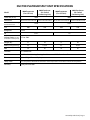
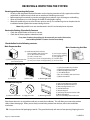
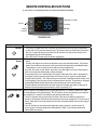
Platinum Split
TECH MANUAL
The Coolest Thing In Wine Storage
We manufacture, test and certify 100% of our wine cooling units in
the USA. By sourcing the best components and closely controlling our
manufacturing processes, we can assure the highest-quality, lowest
defect manufacturing rates in the industry.
Copyright © 2012. WhisperKOOL. All rights reserved.
This manual, the product design, and the design concepts are copyrighted by WhisperKOOL, with all rights reserved. Your rights
with regard to the hardware and manual are subject to the restrictions and limitations imposed by the copyright laws of the
United States of America. Under copyright laws, this manual may not be copied, reproduced, translated, transmitted, or reduced
to any printed or electronic medium or to any machine-readable form, for any purpose, in whole or in part, without the written
consent of WhisperKOOL.
Every effort has been made to ensure that the information in this manual is accurate. WhisperKOOL is not responsible for printing
or clerical errors.
WhisperKOOL reserves the right to make corrections or improvements to the information provided and to the related hardware
at any time, without notice.
Vinothèque and WhisperKOOL are registered trademarks, and ECE is a trademark of WhisperKOOL. All rights reserved.
Mention of third-party products is for informational purposes only and constitutes neither an endorsement nor a
recommendation. WhisperKOOL assumes no liability with regard to the performance or use of these products.
02.07.13
PS 020713
TABLE OF CONTENTS
Quick Reference Guide (Q.R.G)
Controller Layout & Wall Mount Specifications . . . . . . . . . . . .2
Ducted Platinum Split Specifications . . . . . . . . . . . . . . . . . . . . .3
Receiving & Inspecting The System . . . . . . . . . . . . . . . . . . . . . . . . .4
Before You Start . . . . . . . . . . . . . . . . . . . . . . . . . . . . . . . . . . . . . . . . . . . .5
Preparing the Wine Cellar. . . . . . . . . . . . . . . . . . . . . . . . . . . . . . . . . . .6
Preparing the Evaporator Unit (Fan Coil Unit) . . . . . . . . . . . . . .9
Installing the Evaporator Unit (Fan Coil Unit) . . . . . . . . . . . . . . .12
Drain Line . . . . . . . . . . . . . . . . . . . . . . . . . . . . . . . . . . . . . . . . . . . . . . . . . . .14
Evaporator Unit (Fan Coil Unit) Wiring Schematic . . . . . . . . . .15
Preparing The Condensing Unit . . . . . . . . . . . . . . . . . . . . . . . . . . . .16
4000 Condensing Unit Wiring Diagram . . . . . . . . . . . . . . . . . . . . .17
8000 Condensing Unit Wiring Diagram . . . . . . . . . . . . . . . . . . . . .18
8000 Condensing Unit Wiring Schematic . . . . . . . . . . . . . . . . . . .19
Line Set Diagrams . . . . . . . . . . . . . . . . . . . . . . . . . . . . . . . . . . . . . . . . . .21
Installing The Condensing Unit . . . . . . . . . . . . . . . . . . . . . . . . . . . . .22
Q.R.G Wall Mount Kit Option (Installed) . . . . . . . . . . . . . . . . . . . .25
Installing the Wall Mount Kit . . . . . . . . . . . . . . . . . . . . . . . . . . . . . . .26
Fully Ducted Installation Information . . . . . . . . . . . . . . . . . . . . . .28
Q.R.G Ducted Configuration Option ( Installed). . . . . . . . . . . . .29
Installing the Fully Ducted Accessory Kit . . . . . . . . . . . . . . . . . . .30
Remote Keypad Installation . . . . . . . . . . . . . . . . . . . . . . . . . . . . . . . .31
System Operation. . . . . . . . . . . . . . . . . . . . . . . . . . . . . . . . . . . . . . . . . . .32
Remote Controller Functions . . . . . . . . . . . . . . . . . . . . . . . . . . . . . . .33
Troubleshooting Guide . . . . . . . . . . . . . . . . . . . . . . . . . . . . . . . . . . . . .36
Technical Assistance & Accessories . . . . . . . . . . . . . . . . . . . . . . . . .38
WhisperKOOL requires that a certified HVAC-R technician install, Pipe, Evacuate, Charge, Start and Test all split systems.
A Nate Certification is recomended. Please take a moment to review state and city building codes to ensure the safe and
proper installation of the system.
Read, understand and comply with the unit’s installation manual, and piping diagrams.
www.whisperkool.com | Page 1
QUICK REFERENCE GUIDE
Controller Layout
Refer to page 33 for complete listing of buttons
and
°F
°F symbols.
High Bottle Temp
History
Scroll Button
°F
Cellar Pre-Chill
°F
°F
Inactive
(Press and hold 3-5 sec)
Low Bottle Temp
History
°F
Scroll Button
View Set Point
Change Set Point
(Press and hold 3-5 sec)
Power On/Off
Compressor On
Unit is in Pre-Chill Mode
Fans are On
Alarm is Present
Unit is in Anti-Frost Mode
WALL MOUNTED PLATINUM SPLIT UNIT SPECIFICATIONS
Model
Cellar Size (cu. ft.)
Dimensions
20.5”w x 15.5”h x 14.5”d
2000
12”w x 13.5”h x 18”d
20.5”w x 15.5”h x 14.5”d
3650
270
CFM
8000 Condenser
(Air Cooled
Condensing Unit)
8000 Evaporator
(Fan Coil Unit)
1000
BTUh with 90° air entering
the Condenser Coil
Refrigerant
4000 Condenser
(Air Cooled
Condensing Unit)
4000 Evaporator
(Fan Coil Unit)
12”w x 13.5”h x 18”d
4450
190
278
350
R-134a
Condensing Unit HP
1/3++
1/2
Voltage Rating (20 amp 115V or 230V
dedicated circuit required)
Weight (lbs)
56
56
56
66
AMPS (Starting/Running)
2/1
13/8.6
2/1
18/9.5
dBA
54
65
54
65
Drainline
1/2” Condensate
Installation
Evaporator Unit (Fan Coil Unit) is installed in the cellar or up to 25 ducted ft. away, condenser is
installed up to 100 ft
Thermostat
Digital Control Display
Temp. Delta
55°F Temperature differential between the cellar temperature and condenser air intake temperature.
Warranty
2 year parts and labor
Page 2 | 1-800-343-9463
PS 020713
DUCTED PLATINUM SPLIT UNIT SPECIFICATIONS
Model
Cellar Size (cu. ft.)
Dimensions
23.75”w x 15”h x 22.5”d
2000
12”w x 13.5”h x 18”d
23.75”w x 15”h x 22.5”d
3120
200
CFM
8000 Condenser
(Air Cooled
Condensing Unit)
8000 Evaporator
(Fan Coil Unit)
1000
BTUh with 90° air entering
the Condenser Coil
Refrigerant
4000 Condenser
(Air Cooled
Condensing Unit)
4000 Evaporator
(Fan Coil Unit)
12”w x 13.5”h x 18”d
3788
190
200
350
R-134a
HP
1/3++
1/2
Voltage Rating (20 amp 115V or 230V
dedicated circuit required)
Weight (lbs)
57
56
57
66
AMPS (Starting/Running)
2/1
13/8.6
2/1
18/9.5
dBA
54
65
54
65
Drainline
1/2” Condensate
Installation
Use 8” insulated ducting. Ducting should not exceed 25 ft. from the cellar.
Thermostat
Optional Digital Remote Display
Temp. Delta
55°F Temperature differential between the cellar temperature and condenser intake air temperature.
Warranty
2 year parts and labor
www.whisperkool.com | Page 3
RECEIVING & INSPECTING THE SYSTEM
Receiving and Inspecting the System
• Lift only at the designated hand hold locations on the shipping container or fully support the unit from
•
•
•
underneath. A shipment may include one or more boxes containing accessories.
Before opening the container, inspect the packaging for any obvious signs of damage or mishandling.
Write any discrepancy or visual damage on the Bill of Lading before signing.
Allow the condensing unit to sit for 24 hours prior to start up. The condensing unit can be placed in the
installation location piped and evacuated during this time.
Note: WhisperKOOL units are manufactured in the USA and tested prior to shipment.
Review the Packing Slip to Verify Contents
• Check the model number to ensure it is correct.
• Check that all factory options ordered are listed.
If any items listed on the packing slip do not match your order information,
contact WhisperKOOL Customer Service immediately.
Check the Box for the following contents:
Main Evaporator Box
Main Condensing Unit Box
(1) Installation Kit which includes:
(7) #14 2” Phillips Pan Head Screw
(1) 1/2” Drain Tube Connector
(1) 10 ft. 1/2” Drain Line
(1) 10 ½” piece of 1/4” od copper tubing
(1) Platinum Split Evaporator Unit (1) 10 ½” piece of 3/8” od copper tubing
(Fan Coil Unit) Unit
(1) 1/4” copper coupling
(1) 3/8” copper coupling
(1) 1/4” sight glass
(1) 1/4” filter drier
(1) 13’ Power Cord
(1) Condensing Unit
Wall-Mount Accessory Kit
(1) Split System Warranty Checklist
(1) Platinum Split Owners Manual
(1) Warranty Registration Card
(1) 12 ft. Bottle Probe
(10) 6-32 3/8” Phillips Pan Head Screw
(1) Black Strain Relief
(1) Side Grille
(1) Filter Grille
(1) Mounting Bracket
Ducted Accessory Kit
(1) 8” Return Air Plenum
(1)Supply Air Collar
(1) Mounting Bracket
(1) Split System Warranty Checklist
(1) Platinum Split Owners Manual
(1) Warranty Registration Card
(1) 50 ft. Bottle Probe
(1) Remote Keypad
(1) 50 ft. Keypad Communication Cable
(2) Black Strain Relief
(10) 6-32 3/8” Phillips Pan Head Screw
Please leave the unit in its original box until you are ready for installation. This will allow you to move the product
safely without damaging it. When you are ready to remove the product from the box, refer to the installation
instructions.
TIP: Save your box and all packaging materials. They provide the only safe means of transporting/shipping the unit.
Page 4 | 1-800-343-9463
PS 020713
BEFORE YOU START
1. Inspect all components prior to installation. If damage is found, please contact your distributor or WhisperKOOL
Customer Service at 1.800.343.9463.
2. The condensing unit requires a dedicated 115-volt 20-amp circuit. Use a surge protector with the unit. Do not
use a GFI (Ground Fault Interrupter) line.
3. It is REQUIRED to install a drain line to remove condensation from the Evaporator Unit (Fan Coil Unit).
4. The system is intended for use in properly designed and constructed wine cellars. Hire a professional wine
storage consultant with a valid contractor’s license to build your wine cellar.
5. WhisperKOOL requires that all Split Systems are installed by a certified HVAC-R technician. A Nate certified
technician is recommended.
6. Warranty is not active until a Warranty Checklist has been received, reviewed, and approved.
If you encounter a problem with your WhisperKOOL system, please refer to the Troubleshooting Guide on page 36.
If you have any further questions, concerns, or need assistance, please contact WhisperKOOL’s Customer Service at
1.800.343.9463. Please be sure all testing has been completed prior to contacting Customer Service. Please have your
results ready for your representative.
www.whisperkool.com | Page 5
PREPARING THE WINE CELLAR
The performance and life of your system is contingent upon the
steps you take in preparing the wine cellar.
Note: Improperly preparing your enclosure or incorrectly installing your
unit may cause unit failure, leaking of condensation, and other negative side effects.
IT IS HIGHLY RECOMMENDED THAT YOU OBTAIN THE ASSISTANCE
OF A WINE STORAGE PROFESSIONAL.
Wine storage professionals work with licensed contractors, refrigeration technicians, and racking companies to build
well-insulated, beautiful, and protective wine cellars. WhisperKOOL has put together some useful tips to assist in the
installation process. Our recommendations are meant to act as a guide in the process of building a proper enclosure.
Your intended location may have specific needs that we do not address.
Wall & Ceiling Framing
Build wine cellar walls using standard 2x4 or 2x6 construction methods and ceiling joists following the guidelines of
local and state codes in your area. As a general rule, the thicker the walls and the higher the insulation value in your
cellar, the better it will be at maintaining a consistent temperature.
Insulation
Insulation is REQUIRED with the use of the WhisperKOOL product. Standard fiberglass or rigid foam insulation is
normally used in cellar construction or, in some cases, “blown-in” insulation is used. It is very important that all walls
and ceilings are insulated to keep the cellar temperature as consistent as possible during the summer and winter
months. The R-value, or quality of insulation, is determined by the rate at which heat passes through the insulation.
The higher the R-value, the more resistant the insulation is to conducting heat. Using higher R-values in insulation will
lower your operating costs and unit run time. (R-13 minimum, R-19 recommended, R-30 for ceiling and exterior walls.)
Vapor Barrier
Water vapor creates its own pressure, separate from the air pressure, and will intrude into colder/drier areas. A vapor
barrier is REQUIRED to prevent the intrusion of water vapor so that the cellar can be kept at the correct temperature
and humidity. 6 mm plastic sheeting (recommended) should be applied to the warm side of the cellar walls. The
vapor barrier must also be applied to the outside walls and ceiling. If it is impossible to reach the outside, then the
plastic must be applied from within the cellar. The most common method is to wrap the entire interior, leaving the
plastic loose in the stud cavity so the insulation can be placed between each stud. All of the walls and ceiling must be
wrapped in plastic for a complete vapor barrier.
In areas of high humidity, such as Southern and Gulf States, the vapor barrier will prevent infiltration of warm moist
air. The moist air can cause mold to form, and standing water in drain pans promote microbial and fungal growth that
cause unpleasant odors and indoor air quality problems. If mold is found, remove it immediately and sanitize that
portion of the unit. Note: High humidity significantly increases the heat load on the cooling system.
Any break in the vapor barriers (cut, nail hole, over-lapping, etc) will allow a moisture leak and must be sealed. Electric
conduit is a “duct” for vapor to travel in. The conduit should be caulked and sealed on the warm air end.
Page 6 | 1-800-343-9463
PS 020713
Unobstructed Airflow
Unobstructed airflow to and from the Evaporator Unit (Fan Coil Unit) and Condensing Unit is critical for the
system’s overall performance and life-span. A minimum three-foot clearance (five foot is ideal) area is crucial. The air
the fans blow needs to circulate and either dissipate or absorb heat from the space, the more air to exchange the more
efficient the system will operate.
Note: Avoid attempting to camouflage the unit. This will restrict airflow and thus the systems ability to work efficiently.
Keep Clear
Wine Cellar
Mounting the Evaporator Unit (Fan Coil Unit)
The Evaporator Unit (Fan Coil Unit) must be mounted within 18“ of the top of the room in order to achieve
sufficient cooling. As the room cools down, the warm air will rise to the ceiling. Mounting the unit high in the
room will contribute to a consistently cool environment by capturing the warm air and replacing it with cool air.
Mounting the unit low in the room will result in a temperature variation in the room due to the unit’s inability to
draw warm air from the ceiling of the cellar to the unit itself, and cold air settling to the floor.
Door and Door Seal
An exterior grade (1 3/4”) door must be installed as a cellar
door. It is essential that weather stripping is attached to
all 4 sides of the doorjamb. A bottom “sweep” or threshold
is also required. The door must have a very good vapor
seal to prevent warmer moist air from leaking into the
cellar. One of the most common problems with cooling
systems running continually is due to the door not sealing
properly. In cases where glass doors are used and the
room size is close to the recommended system size,
the next larger size WhisperKOOL system should be
used. This will compensate for the insulation loss due to
the lower insulating rating of glass.
www.whisperkool.com | Page 7
Ventilation
The necessity of dissipating heat away from the condensing unit is critical to the performance and cannot be
overstated. As the system operates and cools, a greater amount of heat is generated on the condensing side of the
system. Adequate ventilation is required in order to dissipate heat away from the condensing unit. If ventilation is
inadequate, the exhaust will heat up the area or room and adversely affect the systems ability to cool. In some cases, it
may be advisable to install a vent fan to dissipate heat within the exhaust area on the condensing side of the system.
However, you must have a fresh air inlet as well.
Note: If you are unsure about having adequate ventilation in your install location, please
contact us to assess your specific installation at [email protected] or 1.800.343.9463.
Evaporator Unit
(Fan Coil Unit)
BACK - EXHAUST SIDE
FRONT - WINE CELLAR
Condensing Unit
Exterior Cellar Wall
Ambient Temperature Factor
The cooling system has the ability to cool a wine cellar efficiently to 55°F as long as the ambient temperature of the
area that it is exhausting to does not exceed 110°F. Therefore, you want to exhaust the condensing unit in a space which
will not exceed 110°F. Otherwise the system will not have the capacity to keep the wine at a desirable 55°F.
Warning, allowing your system to operate in high ambient temperatures for
extended periods of time will greatly decrease the life of your system and void
your warranty. The cooler the temperature of the air entering the condenser coil
the more cooling capacity the system has. The less heat gain through the common
wall, the less the electricity consumption.
Page 8 | 1-800-343-9463
PS 020713
PREPARING THE EVAPORATOR UNIT (FAN COIL UNIT)
1
Tools Needed For Brazing:
•
Torch
•
Brazing Rod
•
Wet Rag
•
Inspection Mirror
•
Nitrogen Tank
4
Remove the unit from the packaging. Gather all material
needed for brazing purposes.
copper lines
Remove Protective Caps
2
caps
Insert the supplied 10” copper lines into the couplings.
5
drain Line
Note: Do not remove the caps until you are ready to perform the
brazing process.
3
To prevent oxidizing, purge nitrogen into each
line. Braze each of the copper extensions to
the tubing coming out of the Evaporator Unit
(Fan Coil Unit). Perform a visual inspection and
pressurize test to 200 psig for 15 minutes to
verify there are no leaks.
NOTE: Place a wet rag around the copper tubes
near the rubber grommet located at the rear of the
evaporator housing, this will minimize the possibility
of melting the grommet. Be sure to clear the power
cord and drain line from brazing area.
Place both the 3/8 and the 1/4 copper couplings on the exposed
lines.
www.whisperkool.com | Page 9
PREPARING THE EVAPORATOR UNIT (FAN COIL UNIT)
6
Place the caps removed in step 1 onto
the ends of the lines to avoid debris from
entering the lines, followed by inserting the
barbed coupling into the drain line at the
rear of the unit.
9
7
length to extend past wall
3”
Cut supplied drain tubing at a length long enough to extend
past exterior wall and a second piece three inches long.
8
Rotate the unit to access the side panel.
10
Set the three inch piece aside and attach the piece of tubing
that was cut to go through the wall to the end of the barbed
coupling.
Remove the side panel by removing the eight Phillips head
screws around the parameter of the side panel. Set the side
panel and screws aside.
Page 10 | 1-800-343-9463
PS 020713
PREPARING THE EVAPORATOR UNIT (FAN COIL UNIT)
12
11
Insert bottle probe connector through the opening on the rear
panel.
Circular Connector
Bottle Probe Connector
Connecting the bottle probe to the circular connector: Insert
the bottle probe connector into the circular connector and
twist the bottle probe connector clock wise to lock in place.
Install the supplied strain relief to secure probe wire. Using
pliers, clamp the strain relief around the probe wire and insert
the strain relief into the hole the probe wire is coming from.
(Note: Strain Relief will snap in to place when fully inserted.
Perform a pull test to ensure the strain relief connection is
tight.)
13
www.whisperkool.com | Page 11
INSTALLING THE EVAPORATOR UNIT (FAN COIL UNIT)
1
3
0.75"
3.75"
3"
Locate the two desired wall studs. Mark the center
line on each stud vertically on the wall (14.5 inches
apart). Connect the two lines by using a level draw a
horizontal line at your desired height.
NOTE: The top of the unit needs to be installed
with a minimum of six inches and a maximum of
eighteen inches from the ceiling. ( This will ensure
the unit is accessable for servicing, as needed.)
2
Drill two 5/32” pilot holes for the top mounting
screws and then place the mounting plate on the wall
and screw in the #14 screws. Finish drilling the four
remaining 5/32” pilot holes, followed by screwing in
four #14 screws.
Page 12 | 1-800-343-9463
Cut a 3x3.75 inch access hole for routing the line set,
power cord, and drain line.
The wall is ready to have the Evaporator Unit (Fan Coil
Unit) installed.
NOTE: WhisperKOOL recommends elevating the
unit close to the install height.
4
Route the power cord and drain line through the
access hole.
PS 020713
INSTALLING THE EVAPORATOR UNIT (FAN COIL UNIT)
5
5. Lift the Evaporator Unit (Fan Coil Unit) up and place onto
the wall bracket.
NOTE: Be sure that the power cord
and drain line stay clear of the
bracket contact area
6. Form the copper lines on the outside of the cellar in the
desired direction.
NOTE: WhisperKOOL recommends using sweep 90-degree
bends when making turns with the line set.
With the system operating, sight glass clear, and the
cellar close to 55 degrees Fahrenheit. Check the suction
pressure, the temperature of the suction line at the outlet
of the evaporator, and if necessary adjust the expansion
valve to bring the superheat level between 8-12 degrees.
www.whisperkool.com | Page 13
DRAIN LINE
Condensation Drain Line
The condensation drain line tube is used to remove excess condensation from the Evaporator Unit (Fan Coil Unit) to a
proper discharge location. It is important that the drain line tube is properly connected and used to prevent leakage
and other problems associated with excess condensation.
Failure to use the condensation drain line tube will void the warranty on the unit.
Drain Line
All systems come with a drain line for additional removal of excessive condensate. It is mandatory to install the
drain line whether it leads through the wall and out of the cellar or remains inside the cellar. During operation, the
cooling system will strip excess water from the air in order to maintain the proper level of humidity within the cellar.
However in extreme humidity, additional condensate will be removed. Thus the drain line will prevent overflow and
leaking by allowing for discharge of the additional condensate.
Insert the middle barb of the barbed tee THROUGH THE WALL DRAIN LINE
fitting into to the end of the drain line
OPTION 1
coming from the Evaporator Unit (Fan Coil
Unit). Rotate fitting so tee is in the
NOTE: The fitting should be
orientation shown in the diagram on the
placed vertical with the three
left. Connect the three inch piece from step
inch cut out facing up.
7 of preparing the Evaporator Unit (Fan Coil
Unit), to the barb on top. Connect the
remaining “long” piece of drain tubing to
INSIDE CELLAR DRAIN LINE
the bottom barb of the tee.
OPTION 2
NOTE: The fitting should be placed vertical
with the three inch cut out facing up.
SIDE VIEW
WRONG: Drain line is under water.
Failure to install the drain line
voids the warranty.
To prevent mold from growing,
allow the drain line to hang
above the water line.
Page 14 | 1-800-343-9463
PS 020713
EVAPORATOR UNIT (FAN COIL UNIT) WIRING SCHEMATIC
Capacitor
Evap
Fan
Capacitor
www.whisperkool.com | Page 15
PREPARING THE CONDENSING UNIT
Electrical Needs
The Condensing Unit requires a dedicated 115-volt 20-amp circuit. The unit draws a large inrush current for about
one second the instant the compressor starts. With a dedicated circuit and circuit breaker, the condensing unit will
have sufficient power for effective operation. (The compressor is controlled by a low pressure switch mounted on
the condensing unit. This feature elimintates the need for wiring between the Evaporator Unit (Fan Coil Unit) and the
Condensing Unit.)
• Ensure the voltage supplied matches the rating specified on the unit spec label.
• Provide a non GFI dedicated circuit and an appropriate outlet for the Evaporator Unit’s (Fan Coil Unit) power cord.
• Provide a dedicated circuit and circuit breaker for the Condensing Unit.
• Provide a weatherproof disconnect for Condensing Units located outside.
As with all sensitive electrical equipment, damage may be caused in the event of power surges and spikes. WhisperKOOL
recommends plugging the unit into a surge protector, or power conditioner, in order to protect your system. As outlined
in our terms & conditions, power surges and spikes are not covered under warranty.
WE RECOMMEND THAT YOU DO NOT USE A GROUND FAULT INTERRUPTER (GFI) WITH THIS PRODUCT.
In case the system should lose power, check the home/main circuit breaker. If the system does not respond properly, refer
to the Troubleshooting section on page 36.
Low Ambient Control
High Pressure Cutout
Low Pressure Switch
For the equipment warranty to be valid, WhisperKOOL requires that the installation is performed by a certified
HVAC-R technician (Nate certified technician is recommended) per the specifications outlined in this technician’s
manual. The technician shall be required to be equipped with the proper tools of the trade including: refrigerant 134a,
brazing equipment, dry Nitrogen, an accurate manifold gauge set (digital preferred), plus a four valve manifold set
for evacuation, digital micron gauge, digital scale, deep vacuum pump and accurate digital thermometers. Without
the proper equipment, a professional job cannot be accomplished. Evidence of the certified tech’s NATE# or other
certification is required.
Page 16 | 1-800-343-9463
PS 020713
4000 CONDENSING UNIT WIRING DIAGRAM
C
0
7
8
6
1
www.whisperkool.com | Page 17
8000 CONDENSING UNIT WIRING DIAGRAM
LEGEND:
TERMINAL BOARD
BD # SERVES
GROUND
2
3
4
5
6
7
8
9
10
GREEN
UK GREEN/YELLOW
STRIPE
L1-115V-HOT
BLACK
RED UK-CAN
115V-NEUTRAL WHITE
BLUE UK
CC HEATER
BLACK
COMP GND
GREEN
H-COMP
BLACK
N-COMP
WHITE
H-COND FAN
BLACK
LINE H-LP-HP
BLACK
COMPRESSOR
CRANKCASE
LOAD H-LP-HP BLUE
HEATER
WHITE (NEUTRAL)
BLACK
1
M
UP
S
START
CAPACITOR
2
L
FAN
(CONDENSER)
3 BLUE
RED
1
COLOR
1
C
R
S YELLOW
RELAY
TD=TIME DELAY, DELAY ON BREAK
COMPRESSOR
TERMINAL
OVERLOAD
GREEN
BLACK-H
BLACK-F
WHITE-NEUTRAL
BLACK-C
ENCLOSURE
W
COMP
RELAY
BLACK-NC
1
2
3
4
7
BLACK-C
8
BLACK-NO
6
5
6
1
0
7
BLACK
TD
1 DOB
3
9 10 11
8
G H N 12 13 14 15 16 17 18 19
BLACK-C
WHITE-NEUTRAL
BLACK-F
LP
BLUE
BLACK-H
GREEN
115V 60 HZ
POWER
SOURCE
Page 18 | 1-800-343-9463
HP
BLACK
GREEN
BLACK
WHITE
LOW
AMBIENT
CONTROL
line
m1
PS 020713
8000 CONDENSING UNIT WIRING SCHEMATIC
H
POWER
115v 60 HZ
N
4
CC HEATER
START
CAPACITOR
COMP CONTACTOR
CURRENT
RELAY
6 OL
3
COMPRESSOR
9 HP
10 LP
TD
CC
CC
HP
LP
TD
COMP CONTACTOR
HI PRESS SWITCH
LO PRESS SWITCH
TIME DELAY
7
6
8
LOW AMBIENT
CONTROL
COND.
FAN
www.whisperkool.com | Page 19
PREPARING THE CONDENSING UNIT (continued)
Installing the Condensing Unit
The condensing unit can be installed inside a well ventilated area of the home, but it is typically installed outside.
Exterior applications will require the use of a protective housing, and the amount of sun exposure should be
considered when selecting the placement of the condensing unit .The condensing unit requires a dedicated 20 amp
circuit, non-GFI. Make sure there is a minimum three-foot horizontal clearance in front and rear of the unit. The unit
may either be hard wired or plug-in depending on local electrical codes.
Set the condensing unit level and with proper clearances in accordance with the instructions, name plate power
supplied, proper electric disconnect and fuse protection connected but not turned on and ready for piping
connections.
Inside Condensing Unit Installations: Inside installations require special consideration, as there must
be adequate ventilation to remove the heat created during normal operations. An exhaust port with fan
may need to be installed to ensure that heat is effectively removed from the utility room. A return grille or
provision for 500 - 600 cfm of cool air to enter the room to replace the exhausted air will accomplish this.
Unobstructed airflow to and from the unit is a critical factor in the unit’s overall performance. Make sure there
is a minimum three-foot horizontal clearance in front and rear of the condensing unit and at least one foot on
each side. This will assure that the unit can move the air around the room in an efficient manner.
Outdoor Condensing Unit Installations. You must utilize the exterior condensing unit housing for outdoor
installations. Place the condensing unit on a solid foundation in a location with adequate ventilation. There
should be three feet of clearance in the front and rear of the unit and one foot on each side. The unit should
be elevated 18 inches in order to avoid any possible flooding or damage by animals, and should be clear of
leaves, dirt, and other debris.
Head Pressure Control, Fan Cycling Switch:
These switches are used to cycle the condenser fan at low ambient temperature conditions. If your unit is equipped
with a Low Ambient Control, set the switch to 170 psig for cut-in and 70 psig for the differential. Further adjustment
may be needed. Verify the settings via refrigeration gauge and perform the final adjustments to the readings on the
gauge manifold set. If your condensing unit is not equipped with an adjustible Low Ambient Control, it features a preset Fan Cycling Switch. These controls serve the same purpose, but have different names.
Refrigeration Lines
A 1/4 inch O/D copper “liquid line” is required
It is required to size the suction line tubing according to this chart.
Model
Platinum Split 4000
Platinum Split 4000
Platinum Split 8000
Platinum Split 8000
Line Set Length
Vertical Rice
Horizontal Tubing
Vertical Rise
Horizontal Tubing
Vertical Rise
>3ft
>25ft
26-50ft
50-100ft
3-10ft <10ft >3ft 3-10ft <10ft >3ft 3-10ft <10ft
1/2”
5/8”
3/8”
5/8”
5/8”
1/2”
1/2”
5/8”
1/2”
The refrigerant drier and the sight glass shall be installed (in that order) in the direction of the refrigerant flow in the
liquid line between the condensing unit and Evaporator Unit (Fan Coil Unit). Enclose the suction line in a cellular
insulation ½” wall thickness Armaflex (brand name) or equal to reduce heat transfer.
Page 20 | 1-800-343-9463
PS 020713
LINE SET PIPING DIAGRAMS
These are two options for running the line
set from the coil to the condensing unit.
Option 1 is specifically for when the system
is installed with the condensing unit below
or leveled to the coil. Option 2 is for when
the system is installed with the
condensing unit at a higher
elevation than the coil.
Option 1
Option 2
www.whisperkool.com | Page 21
INSTALLING THE CONDENSING UNIT
Refrigerant Piping Procedures
When installing/routing the lines set, cap both ends of each tube to prevent material or debris from entering the
tubing.
Prior to connecting the piping, loosely connect the refrigerant gauges to the service ports of the suction and liquid
line service valves. Purge the charging hoses with dry Nitrogen and tighten the hose connections. Remove the service
valve caps and turn the valve stem clockwise (half of a complete turn) in order to unseat the valve and open the
service port. The valve comes in a back seated position from the factory. Keep the piping port sealed until ready to
connect to the vacuum pump.
Cleanliness is of the utmost importance. All horizontal suction piping should be pitched toward the condensing unit
1/2” for every 10’ of pipe. During any brazing procedure, dry Nitrogen should be purged through the fitting at a slow
rate to prevent formation of highly abrasive Copper Oxide. Make sure there are no obstructions to the flow which
would cause pressure build up and the brazed fittings to leak. After leak testing and confirming there are no leaks,
insulate suction line with 1/2” wall thickness Armaflex or equal insulation. Seal all seems using Armaflex 520 Foam
Insulation Adhesive or equivalent. Wrap each seam using line set tape.
Liquid Line Piping Procedure
It is required to use a 1/4” OD Copper tube liquid line. When making connections keep the ends sealed until ready to
fit the tube. First connect the supplied refrigerant drier close to the liquid service valve (king valve) on the receiver.
Downstream, connect the moisture indicating sight glass in an easily visible location. Run the tubing to the Evaporator
Unit (Fan Coil Unit) location and fit to the liquid line stub from the Evaporator Unit (Fan Coil Unit). Energize the
Evaporator Unit (Fan Coil Unit) and set the temperature controller to call for cooling, this will activate the liquid line
solenoid valve. Uncap the suction pipe to prevent obstructed Nitrogen flow. Open the Nitrogen to allow a slow flow
and braze the liquid line fitting. Shut off the Nitrogen and power until suction line is brazed.
Suction Piping Procedure
Slide Aramaflex insulation over the tubing for the entire length of the tube and keep the end of tube sealed during
this procedure. Keep the tubing sealed while running the connection points and fit the suction tube to the Evaporator
Unit (Fan Coil Unit) outlet connection. Install a Schrader Type Access valve at the outlet of the Evaporator Unit (Fan
Coil Unit) to allow for superheat checking. If there are brazed fittings along the length of the tube, apply the insulation
after leak testing.
After all piping ran and ready for the brazing process: Energize the Evaporator Unit (Fan Coil Unit) and set the
temperature controller to call for cooling. Open the liquid line service valve and bleed the nitrogen through both
the liquid and suction line. Loosen the suction gauge hose to relieve pressure during the brazing process. Braze the
connections and cool them off quickly. With the solenoid valve still energized, connect the refrigerant cylinder and
add a small amount of 134a to both the high and low sides.
Testing the Low Ambient Control and Leak Testing
Verify the Johnson control is set at 170 for the cut in and 70 for the differential. Remove one wire from the Johnson
Pressure Control and connect an ohmmeter to its two terminals. With pressure below 100 psi, the meter should read
“open circuit”. Using dry nitrogen slowly increase pressure to 170 psi at which pressure the controller should make and
the meter will read “continuity”.
Continue pressure build up to 200 psi. Check to see if there is a noticeable pressure drop, if so locate and fix leak. With
pressure at 200 psi, check for leaks with a refrigerant leak detector and/or soap bubbles. Confirm pressure holds at 200
psi for 30 minutes. If not check again for leaks and repair, perform another leak test. When it is confirmed there are no
leaks, release the nitrogen pressure and leave the solenoid valve energized.
Page 22 | 1-800-343-9463
PS 020713
INSTALLING THE CONDENSING UNIT
Evacuation
Connect evacuation type four valve gauge manifold to high and low pressure service valve ports on the condensing
unit with the valve stems mid seated as when leak testing. Install service caps on valves and tighten them. Energize
the liquid line solenoid valve (make sure there is fresh oil in the vacuum pump). Connect a micron gauge directly to
the pump, blank off and start the pump to verify that it is capable of 200 micron vacuum and the gauge is capable of
reading that vacuum. Connect the micron gauge to the access valve installed in the suction line at the Evaporator Unit
(Fan Coil Unit). Remove the Schrader valve depressors from the gauge hoses to reduce restriction and connect gauges
to the suction and liquid line service valve service ports on the condensing unit. Connect the pump to the 3/8” hose
on the manifold set, start the pump and run until the micron gauge reads 200 microns.
When a 200 micron level evacuation is achieved, break the vacuum with R-134a and add enough refrigerant to
pressurize the system with a few psi of positive pressure.
Charging
Remove the vacuum pump and the micron gauge. Install a spare low pressure gauge to the access valve at the
Evaporator Unit (Fan Coil Unit). With the power off to the condensing unit, place the cylinder of R134a on a digital
scale. Admit liquid refrigerant to the system through the high pressure side,
(Liquid line service valve) until the refrigerant stops flowing or until about three pounds have been added. Shut off
refrigerant flow to system.
Fill a wine bottle ¾ full with water between 60-75 degrees. Insert the bottle probe into the neck of the bottle as far as
possible. (It is important the bottle probe stopper is compressed by the neck of the bottle to ensure water will not leak
out.). Verify that the bottle probe is properly installed and the set point on the controller is low enough to allow the
system to run continuously for 30 minutes or more. Turn on power to the condensing unit and the compressor should
start if suction pressure is above 6 psi. If the system pumps down and the compressor shuts off, set the 5 minute time
delay relay time to the lowest setting to avoid having to wait. Add refrigerant as a vapor through the low pressure side
of the system (suction service valve port).
Observe the sight glass when the compressor starts. If bubbles are present, slowly add more refrigerant in vapor form
to the low side. The suction pressure and head pressure should increase as the sight glass clears. Check the superheat
during the charging process. If the superheat drops to 4 or 5 degrees Fahrenheit and sight glass still has bubbles, let
the unit run until the wine cellar temperature drops and approaches 55 degrees Fahrenheit. Observe the sight glass,
if bubbles are present add additional refrigerant in small increments. Let the system stabilize for about 5 minutes
and check the sight glass for bubbles before adding additional refrigerant. Once the sight glass is clear, check the
superheat at the outlet of the Evaporator Unit (Fan Coil Unit) (evaporator superheat should be between 8-12 degrees
Fahrenheit). If superheat is not between 8 and 12 degrees make an adjustment to the expansion valve. Depending
temperature, the “high side” should be approximately 175lbs, and the “low side” should be 28lbs or more to keep the
Evaporator Unit (Fan Coil Unit) from icing.
www.whisperkool.com | Page 23
INSTALLING THE CONDENSING UNIT (continued)
Measure Superheat
If superheat is high and bubbles are present, add more refrigerant until it is clear. If superheat is low (around 4-6
degrees Fahrenheit) and bubbles are present in the sight glass, check for liquid refrigerant entering the compressor
as evidenced by cool crankcase below 100- 110 degrees Fahrenheit and low discharge superheat. Adjust TXV setting
in small increments to increase superheat and stop liquid from going to the compressor. Check this before adding
more refrigerant. If the temperature of the air entering the condenser is cold enough to cause the condenser fan to
cycle, block about 60% of the coil to raise the head pressure and allow time for stabilization. Reduce blockage if the
condensing temp is above 115 degrees Fahrenheit. Retain blockage if necessary to maintain stability for performance
test listed in the Split System Warranty Checklist. If the air is cold, below 60 degrees Fahrenheit entering the condenser
and the sight glass is clear; allow the system to run for a while until the cellar cools off, then measure and record data
on the Split System Warranty Checklist.
Reinstalled the Evaporator Unit (Fan Coil Unit) panel that was removed in step (10) on page 10. Confirm the controller
is displaying the correct temperature and that the controller is not displaying an alarm. If the controller is displaying
an alarm reference page 34 for corrective action. Confirm that the suction line is completely insulated, from TXV to
compressor. Confirm that the sight glass has no bubbles and the ambient temperature around the condensing unit is
not getting excessively hotter. Confirm that both king valves have been back seated and the nuts have been installed
back on the king service ports.
BEFORE INSTALLING THE WALL MOUNT KIT OR DUCTED CONFIGURATION OPTIONS
Secure the Side Panel by installing the eight Phillips head screws around the parameter of the side panel.
Page 24 | 1-800-343-9463
PS 020713
QUICK REFERENCE GUIDE
Wall Mount Kit Option (Installed)
Evaporator Unit (Fan Coil Unit)
Wall Mount Kit
Filter Grille
Side Air Grille
Controller
Rear / Side View
Mounting Bracket
(pre-installed)
www.whisperkool.com | Page 25
INSTALLING THE WALL MOUNT KIT
1/16”
1
NOTE: The screws should be
installed with about 1/16”
between the face and screw
head.
Install one of the 6-32 3/8” Phillips Pan Head screws, in
each corner of the supply panel.
2
4
Black
Red
Connect the two wires from the keypad to the terminal
block. (Note: If the display does not illuminate on initial
start up, reverse the connection of the two wires.)
Key Hole
3
Install two of the 6-32 3/8” Phillips pan head screws in
the front to completely secure the side air grille to the
Evaporator Unit (Fan Coil Unit).
Mount the side air grille by aligning the four key holes
with the four mounting screws and slide down.
Tighten the bottom two screws and slide down.
Tighten the bottom two screws though the access
holes once the side air grill has been slid into place.
Page 26 | 1-800-343-9463
PS 020713
INSTALLING THE WALL MOUNT KIT
5
1/16”
NOTE: The screws should be
installed with about 1/16”
between the face and screw
head.
Install the remaining four 6-32 3/8” Phillips pan
head screws in the four corners on the front of the
Evaporator Unit (Fan Coil Unit).
6
Install the Filter Grille by aligning the four inside
slotted holes with the four mounting screws and slide
down. Tighten the bottom two screws through the
access holes when the grille is already in place.
WALL-MOUNT
PLATINUM SPLIT
www.whisperkool.com | Page 27
FULLY DUCTED INSTALLATION INFORMATION
Ducting the supply and return air to the cellar creates a virtually silent cellar space and also maximizes cellar capacity.
It is absolutely crucial to only use insulated duct work as it minimizes cooling loss, prevents sweating, and reduces
noise. Failure to use insulated ducting will cause the unit to run excessively and greatly shorten its lifespan.
Note: Do not exceed a total of 25 duct feet between the Evaporator Unit (Fan Coil Unit) and cellar vent, this means a
total of 50’ combined for both the supply and return lengths.
Avoid crimping the flexible ducts. This chokes down the inside area and reduces the airflow causing the unit to lose
efficiency. Be sure all ducts and surfaces in contact with the airflow are insulated and have a vapor barrier on the
outside.
Un-insulated ducts and surfaces cause bare, exposed metal surfaces to sweat, further degrading the insulation
and equipment cooling capacity.
General Duct Recommendations:
• Provide support for the flexible duct to prevent sags and bends
• Stretch out the duct to make a smoother interior, which reduces air resistance
• For 90° bends, use a 90° adjustable elbow (Ell)
• Do not squeeze or reduce the inside diameter of the ducts, which reduces airflow
• Use short and straight duct work where possible
• Remove the grilles and panels from the openings to connect the duct work
• Check that all fan blades move freely
• Keep air paths free of loose foreign objects and debris
• Connect the round flexible ducts to the WhisperKOOL system using the duct collars provided with the duct
accessory kit
• Pull the outer plastic wrapping and insulation away from the end of the duct to expose the reinforced inside
duct liner
• Fasten the duct collar using tie straps or clamps around the inside liner
• Secure the duct collar to the unit using the screws provided. Take care to not damage or bend the gasket
• Use approved duct tape to seal all joints
Do not clamp around the outside insulation,
as it will compress and loosen over time.
Note: When performing a ducted installation, it is crucial
to not forget about routing the bottle probe into the cellar.
The system must have the sensing bottle in the cellar to
maintain the cellar environment.
Page 28 | 1-800-343-9463
PS 020713
QUICK REFERENCE GUIDE
Ducted Configuration Option (Installed)
Evaporator Unit (Fan Coil Unit)
Ducted Configuration
Supply Air Collar
Return Air Plenum
Filter Access Panel
Keypad Connection
www.whisperkool.com | Page 29
INSTALLING THE DUCTED CONFIGURATION
DUCT CONFIGURATIONS
1
Here are two options for ducting the Evaporator Unit (Fan
Coil Unit). Option 1 is to duct the system through the wall.
Option 2 is to duct the system through the ceiling. (All
turns require an elbow.)
Option 1
Install the Supply Air Collar by aligning the holes
with the Evaporator Unit (Fan Coil Unit) on the side
panel, followed by installing the four 6-32 3/8” Phillips
pan head screws in the four holes on the front of the
Evaporator Unit.
2
Secure the return air plenum by aligning the outer
corner holes with the holes on the Evaporator Unit
(Fan Coil Unit), followed by installing the four 6-32 3/8”
Phillips pan head screws in the four holes on the front
of the Evaporator Unit.
NOTE: The top of the registers needs to be installed
with a minimum of six inches and a maximum of
eighteen inches from the ceiling.
Option 2
DUCTED
PLATINUM SPLIT
Page 30 | 1-800-343-9463
PS 020713
REMOTE KEYPAD: INSTALLATION AND CONFIGURATION
If you have a system with a remote keypad, please review this section for installation.
Note: 50 feet of communication line is included, the keypad can be installed up to 300 line feet away. Longer lengths
of communication line can be ordered by calling 1-800-343-9463 ext. 751.
Run your communication line to the desired location, be sure not to have any harsh kinks in the lines route. Attach the
connection wire as shown below, with the red wire in the upper connection slot and the black wire in the lower slot. It
is also important to run your bottle probe line at this time,
Black
Red
Red Wire
Black Wire
To install the remote keypad box, remove the rear mounting bracket and secure the bracket to the wall in the desired
location. When running the communication line through a wall, be sure to run the line in the rear mount position and
insert the supplied plug in the side hole on the box. Reattach the keypad box to the bracket.
Connection wire in Side Mount configuration
Connection wire in Rear Mount configuration
www.whisperkool.com | Page 31
SYSTEM OPERATION
Initial Start-Up
When power is applied to the unit, the control will briefly
display all symbols, and the Snow Flake symbol will be
displayed (if unit is calling for cooling). There may be a
brief delay prior to the evaporator fan turning on. When
the evaporator fan is activated the Fan symbol will be
displayed. The temperature control feature for the
evaporator fan is a feature applicable to WhisperKOOL.
This is the Advance Product Safety Technology (APST),
which ensures that in the possible event of a cooling
deficiency, the heat from the indoor fan will not raise the
temperature of the wine cellar, which could otherwise
have an adverse effect on the wine aging process.
Normal System Cycle
After the Bottle probe has reached the set point (all units
are shipped with the set point of 55°F and a differential
of 1°F). The FON function is an adjustable feature which
allows the customer the convenience of managing
humidity levels in their wine cellar. The FON Function
is a feature that controls the evaporator fan operation
once the set point has been reached. This function allows
the evaporator fan to run and reintroduce humidity
removed during the cooling process. All units come with
this feature turned off. If low humidity is a problem an
increase in this setting will raise the humitiy level. The
FON function is one of the many Customer Preference
Selection features which allow the customer the ability to
fine tune the controls.
the condensing unit.
Bottle Probe Failure Protection
In the event that a Bottle probe should fail, the APST
(Advance Product Safety Technology) will automatically
transition the Refrigeration Compressor cycles to a predetermined time series (based on detailed laboratory
testing), which will ensure that the product is kept within
the safe range.
Remote Key Pad (standard on ducted units)
The remote keypad is designed to give the user the
ability to monitor and change cellar conditions when the
evaporating unit is placed in a remote location outside of
the cellar.
Anti Short Cycle
The Anti Short Cycle ensures that the unit will remain off
for a period of 5 minutes after the unit has reached the
set point to allow the pressure in the refrigeration system
to equalize prior to starting the compressor.
Anti Frost Cycle
The Anti Frost Cycle is a precautionary measure, as icing
or frosting of the coil does not occur during normal
operation. The system will go through a defrost cycle
every 4 hours. During the defrost cycle, the indoor fan
will provide air flow across the indoor coil, which will
evaporate any frost accumulation.
Low Ambient Conditions
If the condensing unit is installed outside (which will
allow the condenser to be exposed to low ambient
temperatures), the condenser fan may cycle on and
off. The purpose of the fan cycling is to maintain
the system high side pressure, which will ensure an
adequate refrigeration process. The fan cycling process
is accomplished by way of a Johnson Control attached to
Page 32 | 1-800-343-9463
PS 020713
REMOTE CONTROLLER FUNCTIONS
If your unit has a remote keypad then you will have the Remote Controller.
High Temp / Pre-Chill
Inactive
Low Temp
Display
Set Point
ON / OFF
TEMPERATURE
Button
Normal Functions
ON/OFF •
The ON/OFF button allows the customer the convenience of turning the refrigeration
system ON or OFF, from the control panel. This feature does not disconnect power from
the unit. In order for the power to be shut off from the unit, the power cord must be
unplugged from the wall receptacle.
• Press the ON/OFF button once for button application.
Up and Down • Use these buttons to scroll up or down the CPSM (Customer Preference Selection Mode)
Arrows
menu.
• Displays the Highest and Lowest temperature sensed by the Bottle Probe. This feature
allows the customer instant access to the recorded data applicable to the Bottle Probe
Temperatures, it can be easily reset to reflect current temperatures.
1. Press the “UP” arrow, or the “Down” arrow once, and the Highest or Lowest Temperature
(Hi/Lo) sensed by the Bottle Probe, will be displayed.
2. To reset the Hi/Lo, press and hold the “Set” button when the Hi/Lo value is displayed on
the Digital Display, continue to hold the “Set” button until “rst” appears on the digital
display and then blinks. This will erase the past recorded “Temperature Data History” and
start recording, from the current time and temperature, forward. Temperatures displayed
would reflect Bottle Probe Temperatures from that point in time, and beyond.
3. The Hi/Lo feature should be reset at initial “Start-Up” and after the Cellar or Cabinet has
obtained normal operating temperatures, which is generally 55°F.
Cellar PreChill (CPC) The CPC Feature is activated by pressing the Up button for 3-5 seconds, and the CPC logo
will be displayed on the digital display. The CPC feature can be terminated by pressing the
Up button for 3-5 seconds, or the feature will self terminate after 6 hrs.
1. The (CPC) Feature may be used to Pre-Chill the Cellar prior to loading it with Warm
Product. The feature will shift the Set Point down to a lower setting of 52°F, for the next 6
hours. After the 6 hour time period, the Set Point will automatically return to the original
Set Point.
2. The CPC feature can be conveniently adjusted to the customer’s specific needs, by
accessing the “Customer Preference Select Mode” (CPSM). See Customer Preference
Select Mode Instructions.
www.whisperkool.com | Page 33
Set 1. Press the “Set” button once and it will display the Set Point. After approximately 5
seconds, the display will return to normal operation and display the Bottle Probe
temperature.
2. Press the “Set” button once and it will display the Set Point. Press the up and down
arrows to change the set point. Press the Set button again and the numbers will blink,
confirming the change in Set Point.
3. Press and hold the “Set” button during the display of the Hi/Low “Temperature Data
History” (hold button unit “rst” blinks on display), and it will erase the past recorded data
file and start recording, from the current time and temperature.
4. Press the “Set” and the “Down Arrow” buttons simultaneously, for 3-5 seconds, and you
will access the “Customer Preference Selection Mode” (CPSM). The CPSM allows the
customer to “Fine Tune” the Control Operating System to their applicable choice.
Alarm The Alarm symbol is shown when the unit encounters an issue that needs attention, the
displayed alarm codes are explained below.
Alarm Codes
Message
Cause
Solution
Bottle Probe is Unplugged
Attach Bottle Probe to Unit
Faulty Bottle Probe Connection
1. Check Bottle Probe attachment at circular connector
2. Check Bottle Probe connection at green terminal block on
back of controller
Defective Bottle Probe
Replace the Bottle Probe
Faulty Evaporator Probe
Connection
Check Evaporator Probe connection at green terminal block on
back of controller
Defective Evaporator Probe
Replace the Evaporator Probe
“HA”
Defective Bottle Probe
Replace the Bottle Probe
“LA”
The Bottle Probe is sensing a
temperature of 4° below the set
point
Allow the room to warm up which will increase the temperature
of the wine
Defective Bottle Probe
Replace the Bottle Probe
The keypad is locked
Hold “Up” and “Down” buttons for 3 to 5 seconds to disable,
“PON” should appear
“P1”
“P2”
“POF”
Page 34 | 1-800-343-9463
PS 020713
CPSM Mode Press the “Set” and the “Down Arrow” buttons simultaneously, for 3-5 seconds, and you will
access the “Customer Preference Selection Mode” (CPSM). The CPSM allows the customer to
“Fine Tune” the Control Operating System to their applicable choice.
The following CPSM options are available for adjustment:
Fon – Humidity Management Enhancement: This parameter is normally set at 0, which
should provide adequate relative humidity for the cellar.
• An increase in this parameter will increase the Humidity Enhancement (%RH), and a
decrease in the parameter will decrease Humidity Enhancement (%RH).
• Adjustments should be made in increments of 5, with a maximum of 15, and a minimum
of 0.
• After any adjustment to Humidity Enhancement, you should wait a minimum of three
days before making any additional adjustments. This will allow the cellar sufficient time
to acclimate to the new setting.
Fof - Humidity Management Enhancement: This parameter is normally set at 15. This
parameter should not be adjusted, as it simply provides an OFF cycle time for the fan,
during the compressor OFF cycle. However, the parameter is located within the CPSM as a
convenience to the customer, should it need to be adjusted. CCT - Cellar Pre-Chill Duration:
This parameter is set to 6 hours, but can be changed between 0-23.5 hours.
Con/Cof – Compressor On time (Con) and Off time (Cof ) with a Probe 1 failure/Alarm. These
parameters are set at Con 40 min/Cof 10 min. In the event that there is a Probe 1 failure/
Alarm, the compressor/refrigeration system automatically starts a predetermined ON/OFF
cycle, which is controlled by the Con and the Cof parameters. The customer can adjust these
parameters to maintain the desired Bottle temperature.
www.whisperkool.com | Page 35
TROUBLESHOOTING GUIDE
Unit has ice forming on the Evaporator Unit (Fan Coil Unit)
Possible Cause
Solution
Evaporator filter or coil is dirty.
Remove the filter and wash, then clean the coil with a vacuum.
If coil is very dirty, use a spray bottle with a small amount of
liquid dish washing detergent or coil cleaner. Spray coil, let set
for 5 min, then flush with fresh water.
There is something blocking the supply and or return air
Remove blockage
The evaporator fan is not turning on.
Call a service tech to troubleshoot
The Evaporator Unit (Fan Coil Unit) has not gone through
its anti-frost sequence, yet.
Check for ice in the depth of the coil. Melt with blow drier
until coil is warm to the touch. Soak up water with a towel.
If Evaporator Unit (Fan Coil Unit) continues to ice.
Observe ice formation pattern. If only part way up the coil
face, the system could be low on refrigerant. If all the way
up, the coil may be dirty or airflow is blocked.
Unit does not run/power up
Possible Cause
Solution
Evaporator Unit (Fan Coil Unit) is not plugged in
Make sure the unit is plugged into an outlet
Power switch not on
Turn unit on by pressing the power button on the control
Line voltage is incorrect rating for the system
Check line voltage to make sure there is 110v/120v
Bottle at set point
Lower set point
Thermostat not calling for cooling
Lower set point
Faulty thermostat or wiring
Call Customer Service at 1-800-343-9463
Cellar Temperature is to Warm
Possible Cause
Solution
The temperature or the room condensing unit is
exhausting to has exceeded 110°F
Intake temperature needs to drop below 85°.
The system is undersized for the cellar.
Order correct size system
There is something blocking the supply and/or return air,
on the Evaporator Unit (Fan Coil Unit) or the Condensing
Unit.
Remove air flow obstruction
Evaporator Unit (Fan Coil Unit) is mounted too low in the
cellar
Re-Locate unit so the distance from the ceiling and top of
the unit is no more than 18”
One or more of the fans are not turning on.
Please contact the installing technician to troubleshoot.
Compressor is not turning on.
Please contact the installing technician to troubleshoot.
Compressor keeps cycling on overload
Make sure all fans are working and there are no airflow
obstruction.
Poor seal around door or other areas requiring a seal
(around the unit, wall joints, etc)
Make sure there are no air gaps around the door. If door
seal is damaged, replace it.
Controller set too high
Lower the set point.
Evaporator coil is frosted or iced up
Observe ice formation pattern. If only part way up the
coil face, Evaporator Unit (Fan Coil Unit) could be low on
refrigerant. If so, contact your installing technician to assist
with troubleshooting.
System Runs Constantly
Possible Cause
Leaky door seal or poorly insulated cellar.
Page 36 | 1-800-343-9463
Solution
Fix leaky door seal and insulate cellar in accordance with
this manual. (Page 9)
PS 020713
TROUBLESHOOTING GUIDE
Unit leaks water
Possible Cause
Solution
Evaporator Unit (Fan Coil Unit) is not level
Evaporator Unit (Fan Coil Unit) should be level on the wall to
prevent leaking.
Drain line clogged or kinked
Check drain line to make sure water can flow freely.
Drain is clogged preventing water form escaping
Disconnect drain and clear out, open access door and check
drain for blockage
Drain line does not have a downward slope
Fix Drain line so there is a downward slope from the unit to the
drain.
Coil is iced causing drain pan ice and water overflowing
Melt ice with blow drier. Soak up with a towel
Unit runs but does not cool
Possible Cause
Solution
Lack of air flow
Make sure fan is unobstructed; Make sure the evaporator filter,
evaporator coil, and condenser coil are clean and free of debris.
System undersized
Contact Customer Service at 800-343-9463
Compressor is overheating
Shut system off for 1 hour to allow compressor to cool. Turn back
on and check for cooler air flow out. If compressor runs, check
for and clean condenser coil as possible cause of compressor
overheating. If problem repeats, contact you installing technician
to assist with troubleshooting.
Evaporator fan runs but compressor does not
Possible Cause
Solution
Running an Anti-Frost Cycle
1) If the system is maintaining the correct cellar temperature
and there is a dripping snowflake symbol illuminated on the
control, the system is going through an anti frost cycle. No action
Required. 2) If the system is not maintaining the correct cellar
temperature this may be caused by a dirty evaporator filter or
coil. 3) Call installing technician to troubleshoot as the system
may be low on charge or an adjustment to the TXV.
Compressor and/or starting components faulty
Please contact the installing technician to troubleshoot.
System may be performing the WHM function
Allow cooling system to revert back to cooling mode.
Compressor may have overheated.
Shut system off for 1 hour to allow compressor to cool. Turn back
on and check for cooler air flow out. If compressor runs, check
for and clean condenser coil as possible cause of compressor
overheating. If problem repeats, contact you installing technician
to assist with troubleshooting.
Compressor runs but evaporator fan does not
Possible Cause
Solution
Faulty fan motor
Please contact the installing technician to troubleshoot.
Faulty Controller
Please contact the installing technician to troubleshoot.
Compressor short cycles
Possible Cause
Solution
Evaporator Unit (Fan Coil Unit) blows on bottle probe
Move bottle probe to a more central location.
System low on refrigerant charge
Please contact the installing technician to troubleshoot.
Condensing fan motor/capacitor faulty
Please contact the installing technician to troubleshoot.
Compressor and /or starting components faulty
Please contact the installing technician to troubleshoot.
Humidity in cellar too low
Possible Cause
Not enough moisture
Solution
Raise the Fon setting to increase the humidity level
www.whisperkool.com | Page 37
TECHNICAL ASSISTANCE
WhisperKOOL Customer Service is available Monday through Friday from 6:00 a.m. to 4:00 p.m. Pacific Time.
The customer service representative will be able to assist you with your questions and warranty information more
effectively if you provide them with the following:
• The model and serial number of your WhisperKOOL systems.
• Location of unit and installation details, such as ventilation, ducting, construction of your wine cellar, and
room size. Photos of the cellar and installation location may be needed.
Contact WhisperKOOL Customer Service
1738 E. Alpine Ave
Stockton, CA 95205
www.WhisperKOOL.com
Email: [email protected]
Phone: (209) 466-9463
US Toll Free 1(800) 343-9463
Fax (209) 466-4606
ACCESSORIES FOR COOLING UNITS
WhisperKOOL offers accessories to enhance and customize your wine cooling unit.
Exterior Housing
Protects the Condensing unit from the weather elements when the unit is located outside.
Condensate Pump Kit
The condensate pump kit is designed as an automatic condensate removal pump for water dripping out of our
Evaporator Unit’s (Fan Coil Unit’s) drain line. The pump is controlled by a float/switch mechanism that turns the pump
on when approximately 2-1/4” of water collects in the tank, and automatically switches off when the tank drains to
approximately 1-1/4”. The condensate pump kit allows the excess condensate to be pumped up to 20ft away from the
unit.
Accessories can be purchased at www.whisperkool.com
Page 38 | 1-800-343-9463
PS 020713
NOTES
www.whisperkool.com | Page 39
WhisperKOOL
1738 E. Alpine Ave
Stockton, CA 95205
1(800) 343-9463
www.whisperkool.com