1
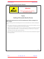
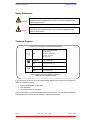
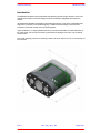
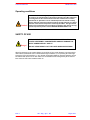
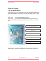
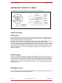
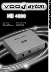
MD4000 CAMERA
Operator & Installation Manual
The electronic version of this document is the controlled copy. Therefore
all printed versions of this document are uncontrolled.
For the latest manual revision always visit – www.tritech.co.uk
Supplied by
Issue 2
TIL – Eng – Spec – 032
MD4000 Camera OIM
COPYRIGHT
© Tritech International Ltd
The copyright in this document is the property of Tritech International
Limited. The document is supplied by Tritech International Limited on the
understanding that it may not be copied, used, or disclosed to others except as
authorised in writing by Tritech International Limited.
Tritech International Limited reserved the right to change, modify and update
designs and specifications as part of their ongoing product development
programme.
F063.1
Tritech International Ltd
MD4000 Camera OIM
Handling of Electrostatic-Sensitive Devices
5
Warranty Statement
6
Safety Statements
7
Technical Support
7
Introduction
8
Operating conditions
9
SAFETY OF USE
9
Disassembly Procedure
10
Camera Internal Layout
11
Setting up Procedures
12
Long line amplifier (Rev B)
12
Control Functions
13
LED Control
13
FOCUS Control
13
OPTIONAL Control
13
LED Typical Spectral Content
14
LED Typical Beam Plot
14
APPENDIX 1
15
Issue 2
Product Specification
TIL – Eng – Spec – 032
Page 4 of 15
Tritech International Ltd
MD4000 Camera OIM
Handling of Electrostatic-Sensitive Devices
Attention
Observe Precautions for handling
Electrostatic Devices
Caution
Handling of Electrostatic-Sensitive Devices
Certain semiconductor devices used in the equipment are liable to damage due to
static voltages.
Observe the following precautions when handling these devices in their unterminated state, or sub-units containing these
devices:
•
Persons removing sub-units from any equipment using electrostatic sensitive devices must be earthed by a wrist strap
via a 1MΩ resistor to a suitable discharge reference point within the equipment.
•
Soldering irons used during any repairs must be low voltage types with earthed tips and isolated from the Mains
voltage by a double insulated transformer. Care should be taken soldering any point that may have a charge stored.
•
Outer clothing worn must be unable to generate static charges.
•
Printed Circuit Boards (PCBs) fitted with electrostatic sensitive devices must be stored and transported in appropriate
anti-static bags/containers.
F110.0
Issue 2
TIL – Eng – Spec – 032
Page 5 of 15
Tritech International Ltd
MD4000 Camera OIM
Warranty Statement
Tritech International Limited herein after referred to as TIL
TIL warrants that at the time of shipment all products shall be free from defects in material and workmanship and suitable for the
purpose specified in the product literature.
The unit/system warranty commences immediately from the date of customer acceptance and runs for a period of 365 days. Customer
acceptance will always be deemed to have occurred within 72 hours of delivery.
Note: Any customer acceptance testing (if applicable) must be performed at either TIL premises or at one of their approved distributors
unless mutually agreed in writing prior to despatch.
Conditions:
These include, but are not limited to, the following:
1
The warranty is only deemed to be valid if the equipment was sold through TIL or one of its approved distributors.
2
The equipment must have been installed and commissioned in strict accordance with approved technical standards and
specifications and for the purpose that the system was designed.
3
The warranty is not transferable, except or as applies to Purchaser first then to client.
4
TIL must be notified immediately (in writing) of any suspected defect and if advised by TIL, the equipment subject to the
defect shall be returned by the customer to TIL, via a suitable mode of transportation and shall be freight paid.
5
The warranty does not apply to defects that have been caused by failure to follow the recommended installation or
maintenance procedures. Or defects resulting from normal wear & tear, incorrect operation, fire, water ingress, lightning
damage or fluctuations in vehicles supply voltages, or from any other circumstances that may arise after delivery that is
outwith the control of TIL.
(Note: The warranty does not apply in the event where a defect has been caused by isolation incompatibilities.)
6
The warranty does not cover the transportation of personnel and per diem allowances relating to any repair or replacement.
7
The warranty does not cover any direct, indirect, punitive, special consequential damages or any damages whatsoever arising
out of or connected with misuse of this product.
8
Any equipment or parts returned under warranty provisions will be returned to the customer freight prepaid by TIL
9
The warranty shall become invalid if the customer attempts to repair or modify the equipment without appropriate written
authority being first received from TIL.
10
TIL retains the sole right to accept or reject any warranty claim.
11
Each product is carefully examined and checked before it is shipped. It should therefore be visually and operationally checked
as soon as it is received. If it is damaged in anyway, a claim should be filed with the courier and TIL notified of the damage.
Note: TIL reserve the right to change specifications at any time without notice and without any obligation to incorporate new
features in instruments previously sold.
Note: If the instrument is not covered by warranty, or if it is determined that the fault is caused by misuse, repair will be billed
to the customer, and an estimate submitted for customer approval before the commencement of repairs.
F167.1
Issue 2
TIL – Eng – Spec – 032
Page 6 of 15
Tritech International Ltd
MD4000 Camera OIM
Safety Statements
Caution!
Throughout the manual certain safety or operational related comments and
requirements will be highlighted to the operator by indications identified by the
adjacent symbol and text.
Throughout the manual certain safety or operational related comments and
requirements that could lead to injury or loss of life will be highlighted by the
adjacent symbol and text.
Danger!
Technical Support
Contact your local agent or Tritech International Ltd
Mail
Tritech International Ltd.
Peregrine Road,
Westhill Business Park,
Westhill, Aberdeen,
AB32 6JL, UK
Telephone
++44 (0)1224 744111
Fax
++44 (0)1224 741771
Email
[email protected]
Web
www.tritech.co.uk
An out-of-hours emergency number is available by
calling the above telephone number
If you have cause to use our Technical Support service, please ensure that you have the following
details at hand prior to calling:
•
•
•
System Serial Number (If applicable)
Fault Description
Any remedial action implemented
Due to the expansion of equipment capabilities and the fact that new sub-modules are continually
being introduced, this manual cannot detail every aspect of the operation.
Issue 2
TIL – Eng – Spec – 032
Page 7 of 15
Tritech International Ltd
MD4000 Camera OIM
Introduction
The MD4000 underwater camera represents the ultimate synthesis of high resolution colour CCD
module with the latest in LED technology to produce the definitive integrated small inspection
camera.
As standard the MD4000 incorporates an automatic light sensing circuit which compensates LED
brightness in proportion to the ambient lighting. In addition external voltage controls are also
provided for focus and manual control of LED brightness.
Again as standard, a 3 stage selectable line driver provides compensation for cable attenuation of
the video signal, and the camera module is protected from damage in the event of an accidental
misconnection.
The overall package provides an extremely useful and robust camera for use in the harshest of
environments.
Issue 2
TIL – Eng – Spec – 032
Page 8 of 15
Tritech International Ltd
MD4000 Camera OIM
Operating conditions
Caution!
The camera has been designed primarily for underwater operations and in
air usage is not optimised due to the heat produced by the LED’s. Water has
a cooling effect on the camera which means that it will become hot when
operated in air. Operation in air for extended periods will activate a safety
device within the electronics which will reduce the light emission as a direct
function of the internal temperature reached by the LED’s. The light should
not be used out with the limit of conditions specified in this manual. For any
special requirement please contact TRITECH INTERNATIONAL LTD.
SAFETY OF USE
THE LIGHT RADIATION EMITTED FROM THE CAMERAS LED
LIGHTS IS EXTREMELY CONCENTRATED AND MAY DAMAGE THE
EYE IF SHINED DIRECTLY ONTO IT.
Danger!
DO NOT STARE DIRECTLY AT THE LIGHTS WHEN OPERATIONAL
When first powered on the camera lighting circuit will be in DLC mode (Dynamic Light Control) this
means that in a darkened area or normal ambient light conditions (i.e. not pointing at a direct light
source) the LED’s will emit light– i.e. any dimmer commands initiated on previous operation will not
be retained after switch off. For this reason it is not advisable to be looking directly at the camera
face where the LED’s are located at switch on.
Issue 2
TIL – Eng – Spec – 032
Page 9 of 15
Tritech International Ltd
MD4000 Camera OIM
Disassembly Procedure
STEP 1
STEP 2
Turn the camera underside up
and remove the 4 x 2.5mm hex
bolts from the base-plate.
STEP 4
The base-plate can now be
removed revealing the ends
of the nylon securing cord.
STEP 3
Prise out one end of the cord
using a sharp implement
such as tweezers (shown).
STEP5
The nylon retaining cord
can now be pulled out
from around the housing.
With the camera on a flat surface,
hold the body housing in one hand
and the head housing in the other
then simply pull apart.
Reassembly is simply the reverse of the five step procedure detailed above.
Caution!
Issue 2
Maintenance of water integrity is the responsibility of the user.
Internal damage caused by water ingress is not covered by product warranty
unless the cause can clearly be identified as a manufacturing defect.
TIL – Eng – Spec – 032
Page 10 of 15
Tritech International Ltd
MD4000 Camera OIM
Camera Internal Layout
FOCUS DRIVE GEAR
LIGHT CONTROL PCB
PSU & FOCUS PCB
VIDEO AMPLIFIER PCB
INTERCONNECT PCB
Issue 2
TIL – Eng – Spec – 032
Page 11 of 15
Tritech International Ltd
MD4000 Camera OIM
Setting up Procedures
Long line amplifier (Rev B)
If there is a need to drive a long coaxial cable then the video amplifier board is required (Seen
pictured below). A solder link can be made in one of the three possible positions to set the
compensation circuit for the long line amplifier. Unless otherwise agreed the camera will always be
supplied with the solder link in position SS1. Video line protection is provided via a quick blow
250mA fuse at F1.
Position 1- SS1 ______unity gain (standard buffered video output)
Position 2- SS2 ______high frequency boost (standard buffered video output with colour boost)
Position 3- SS3 ______high frequency and DC boost gain variable using VR1 (As with setting SS2
but allows manual adjustment of signal amplitude via variable resistor at VR1 up to a maximum of
(2Vp-p).
VR1 VARIABLE RESISTOR
VIDEO FUSE F1
SOLDER SPLASH CONNECTOR SS1
SOLDER SPLASH CONNECTOR SS2
SOLDER SPLASH CONNECTOR SS3
IMPORTANT – When selecting and changing the video line compensation settings via the solder
bridges at SS1, SS2 & SS3 ensure that only one solder connection is made at any one time on the
board. For example – if SS3 setting is required then SS1 & SS2 do not require soldered as well.
Issue 2
TIL – Eng – Spec – 032
Page 12 of 15
Tritech International Ltd
MD4000 Camera OIM
UNDERWATER CONNECTOR – FEMALE
The Underwater Connector supplied is 6-way; the wiring code is shown below.
1
FOCUS +\-
1
6
2
2
3
5
LIGHTS +\-
4
Connector
Face View
3
+12 to 48v DC
0v DC
4
5
VIDEO OUT
6
AM LIGHT TOGGLE
Yellow
Blue
Red
Black
Green
Screen
Control Functions
LED Control
On initial power on the camera will be in Dynamic Light Control mode. This means that the LED’s
will react automatically to any changes in the light reflectivity of the scenery: - In darker areas the
LED’s will brighten and the reverse in lighter areas.
Manual control of the LED’s can be obtained by applying an analogue voltage to PIN2 of any value
in between -12 to -24V which is referenced to the 0VDc on pin4; this will dim the LED’s.
To increase the light output a positive voltage anywhere between +12 and 24V is required on PIN2.
As soon as an analogue voltage is applied to PIN2 then the LED control remains locked in manual
mode to revert back to automatic can be done either by switching the camera off and then back on
again or by applying +12V to +24V to the ‘AM LIGHT TOGGLE’ line on pin6 (this need only be
applied momentarily).
FOCUS Control
Focusing is controlled by applying an analogue voltage to PIN1 of any value in between -12 to -24V
or +12 to +24V which is referenced to the 0VDc on pin4. The negative \ positive control voltages
will drive the focus control motor either clockwise or anticlockwise allowing very fine adjustments in
focusing. There is no danger in holding the focus control on continually as there is no drive limiter
and the focus will never hit a stop, the lens will just move in and out continually switching between
near and far focus.
OPTIONAL Control
The camera may also be controlled with wiring configured for ‘Tri-state’ operation cantered around
5V Dc. If required please contact Tritech for details.
Issue 2
TIL – Eng – Spec – 032
Page 13 of 15
Tritech International Ltd
MD4000 Camera OIM
LED Typical Spectral Content
LED Typical Beam Plot
Issue 2
TIL – Eng – Spec – 032
Page 14 of 15
Tritech International Ltd
APPENDIX 1
Issue 2
MD4000 Camera OIM
Product Specification
TIL – Eng – Spec – 032
Page 15 of 15