1
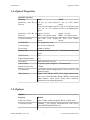
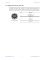
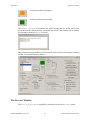
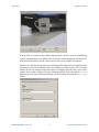
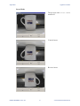
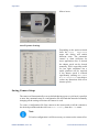
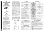
0708-SOM-00001, Issue: 01
Typhoon Camera
Typhoon Camera
User Guide
0708-SOM-00001, Issue: 01
1
© Tritech International Ltd.
Typhoon Camera
© Tritech International Ltd
The copyright in this document is the property of Tritech International Ltd. The document is supplied by Tritech International Ltd on the
understanding that it may not be copied, used, or disclosed to others except as authorised in writing by Tritech International Ltd.
Tritech International Ltd reserves the right to change, modify and update designs and specifications as part of their ongoing product development
programme.
All product names are trademarks of their respective companies.
0708-SOM-00001, Issue: 01
2
© Tritech International Ltd.
Typhoon Camera
Table of Contents
Help & Support ........................................................................................................ 4
Warning Symbols ..................................................................................................... 5
1. Specification ........................................................................................................ 6
1.1. Dimensions Diagram ................................................................................ 6
1.2. Electrical Properties .................................................................................. 6
1.3. Physical Properties ................................................................................... 6
1.4. Optical Properties ..................................................................................... 7
1.5. Options ...................................................................................................... 7
1.6. Standard Connector Pin-Out ..................................................................... 8
2. Introduction .......................................................................................................... 9
3. Installation .......................................................................................................... 10
3.1. General Guidelines ................................................................................. 10
3.2. Test Cable Wiring .................................................................................. 10
4. Operation ............................................................................................................ 11
4.1. Overview ................................................................................................. 11
4.2. Graphical User Interface ......................................................................... 11
4.3. Using Other Interfaces ............................................................................ 19
5. Maintenance ....................................................................................................... 20
Glossary .................................................................................................................. 21
0708-SOM-00001, Issue: 01
3
© Tritech International Ltd.
Typhoon Camera
Help & Support
First please read this manual thoroughly (particularly the Troubleshooting section,
if present). If a warranty is applicable, further details can be found in a Warranty
Statement at the end of the manual.
Tritech International Ltd can be contacted as follows:
Mail
Tritech International Ltd
Peregrine Road
Westhill Business Park
Westhill, Aberdeenshire
AB32 6JL, UK
Telephone
++44(0)1224 744 111
Fax
++44(0)1224 741 771
Email
[email protected]
Website
www.tritech.co.uk
Prior to contacting Tritech International Ltd please ensure that the following is
available:
1. The Serial Numbers of the product and any Tritech International Ltd equipment
connected directly or indirectly to it.
2. Software or firmware revision numbers.
3. A clear fault description.
4. Details of any remedial action implemented.
Contamination
If the product has been used in a contaminated or hazardous environment
you must de-contaminate the product and report any hazards prior to
returning the unit for repair. Under no circumstances should a product be
returned that is contaminated with radioactive material.
The name of the organisation which purchased the system is held on record at
Tritech International Ltd and details of new software or hardware packages will be
announced at regular intervals. This manual may not detail every aspect of operation
and for the latest revision of the manual please refer to www.tritech.co.uk
Tritech International Ltd can only undertake to provide software support of systems
loaded with the software in accordance with the instructions given in this manual. It
is the customer's responsibility to ensure the compatibility of any other package they
choose to use.
0708-SOM-00001, Issue: 01
4
© Tritech International Ltd.
Typhoon Camera
Warning Symbols
Throughout this manual the following symbols may be used where applicable to
denote any particular hazards or areas which should be given special attention:
Note
This symbol highlights anything which would be of particular interest to
the reader or provides extra information outside of the current topic.
Important
When this is shown there is potential to cause harm to the device
due to static discharge. The components should not be handled without
appropriate protection to prevent such a discharge occurring.
Caution
This highlights areas where extra care is needed to ensure that certain
delicate components are not damaged.
Warning
DANGER OF INJURY TO SELF OR OTHERS
Where this symbol is present there is a serious risk of injury or loss of life.
Care should be taken to follow the instructions correctly and also conduct
a separate Risk Assessment prior to commencing work.
0708-SOM-00001, Issue: 01
5
© Tritech International Ltd.
Typhoon Camera
1. Specification
Ø92
1.1. Dimensions Diagram
189
206
Shows standard aluminium alloy housing
Not to scale, dimensions in mm.
1.2. Electrical Properties
Electrical Properties
Property
Details
Voltage range
12 to 30V DC
Zoom & focus control
Analog ±12 to 24V DC or RS232 serial interface
Power consumption
5W at 24V
1.3. Physical Properties
Physical Properties
Property
Details
Weights
1.9kg in air, 0.7kg in water (aluminium alloy housing)
Depth rating
4000m standard (6000m option)
Temperature range
-20°C to 50°C storage
-10°C to 35°C operating
Shock
DEF STAN 00-35 Part 3, chapter 2-03
30gn for 6ms in each axis (while operating)
Vibration
DEF STAN 00-35 Part 3, chapter 2-01
Sinusoidal sweep & dwell in each axis from 5 to 150Hz
at 10gn
Standard connector
Tritech 6 pin
Housing material
Hard anodised aluminium alloy, stainless steel 316 or
titanium alloy 6AL4V
Lens material
Acrylic
0708-SOM-00001, Issue: 01
6
© Tritech International Ltd.
Specification
Typhoon Camera
1.4. Optical Properties
Optical Properties
Property
PAL
NTSC
Sensitivity with IR cut 1.0 lux at 1/60s shutter
filter on
speed
0.1 lux at 1/4s shutter speed
0.05 lux at 1/2s shutter
speed
1.0 lux at 1/50s shutter
speed
0.1 lux at 1/3s shutter speed
0.05 lux at 1s shutter speed
Sensitivity with IR cut approx. 0.01 lux
filter off
B&W, 1/4s shutter speed
approx. 0.01 lux
B&W, 1/3s shutter speed
Vertical resolution
540 lines
speed)
(1/4s
shutter 470 lines
speed)
(1/3s
shutter
CCD Module
1/4" progressive scan
Viewing angle
66° in water (diagonal)
Focus range
10mm to infinity
Primary lens
3.6mm to 82.8mm (f/1.6 to f/3.6) Ivanoff water corrected
optics
Optical zoom
x23
Digital magnification
x12
Iris control
DSP controlled Auto Iris
Video output
1V peak to peak composite, 75Ω unbalanced
Signal to noise ratio
>50dB
GUI functions
Save/load custom configurations, video preview, reset
default settings.
Other features
Digital Slow Shutter (DSS), Back light compensation,
auto focus, Wide Dynamic Range (WDR), auto/manual
white balance, video freeze, frame noise reduction,
minimum focus length adjustment.
1.5. Options
Options
Property
Details
Video Line Driver
Up to 1500m with good quality RG59 coaxial cable
Connector options
Schilling 7 pin SeaNet, Burton/Seacon 5506 Series,
Subconn BH and MCBH Series
0708-SOM-00001, Issue: 01
7
© Tritech International Ltd.
Specification
Typhoon Camera
1.6. Standard Connector Pin-Out
The standard connector fitted to the Typhoon camera is the Tritech International Ltd
6-pin 4000m water block. Other connectors are available and for the standard pin-out
for analogue or serial control for alternative connectors please refer to the original
purchase order for the camera (or contact Tritech International Ltd technical support).
Tritech Waterblock
0708-SOM-00001, Issue: 01
Pin
Function
1
Focus/RS232 Tx
2
Zoom/RS232 Rx
3
+DC Power
4
-DC Power
5
Video Out
6
AutoFocus
8
© Tritech International Ltd.
Typhoon Camera
2. Introduction
The Typhoon colour zoom camera incorporates the latest innovations in CCD sensor
technology enhanced by digital signal processing to adjust the shutter speed, white
balance and back lighting to maximise the low-light working capabilities.
A switch mode power supply board provides all the necessary voltages for the camera
module. The module is controlled internally by RS232 providing full adjustment of
all camera functions.
In addition external voltage controls are provided for focus and zoom. A three stage
line driver is available to compensate for cable attenuation of the video signal.
The camera module is protected from damage in the event of an accidental
disconnection, a water-corrected lens is fitted to optimise picture quality and the
overall package provides an extremely robust unit for use in harsh environments.
Note
The camera is factory configured to be either PAL or NTSC, if a change
is desired to an existing product, please contact Tritech International Ltd
for the available options.
0708-SOM-00001, Issue: 01
9
© Tritech International Ltd.
Typhoon Camera
3. Installation
3.1. General Guidelines
The unit should be clamped securely around the body-tube. Non metallic clamps are
preferable to reduce the risk of corrosion.
It may not be possible to determine the orientation prior to installation so it is
advisable to install the camera in such a way that rotation of the unit is possible to
correct for any mis-alignment of the displayed image.
Caution
Ensure the correct polarity of the power supply cable prior to connecting
the lead. Incorrect polarity may cause damage to the internal electronics.
Before attaching the connector to the camera ensure that the 'O' ring gasket is in
position and lightly smeared with lubricant (Dow Corning #111 or equivalent is
recommended).
3.2. Test Cable Wiring
To connect the camera to a computer for testing or operation it will be necessary
to construct an appropriate test cable. The pin-out diagram for units fitted with the
Tritech 6 pin standard water block is shown in the specification section, for any other
connectors it will be necessary to refer to the documentation that was provided with
the camera to establish the correct wiring scheme.
To connect to a computer it will be necessary to provide the camera a minimum of
three connections:
1. The RS232 serial for passing control commands
2. DC Power and ground
3. The video capture output.
0708-SOM-00001, Issue: 01
10
© Tritech International Ltd.
Typhoon Camera
4. Operation
4.1. Overview
The camera is compatible with any video recorders or monitors working on the PAL
or NTSC standards.
Note
The typhoon is designed for use under water. While in use the surrounding
water will have a cooling effect on the body and use out of water should
be kept to a minimum to avoid shortening the life of the electrical
components.
During power up there will be a delay of several seconds while the camera module
initialises. During this time the monitor will remain dark.
4.2. Graphical User Interface
The Typhoon camera is supplied with software which provides a user interface that
can control the functions of the camera and display the image output. This is useful
for bench testing prior to deployment and can also be used for simple setups where
the camera is connected directly to a computer.
The software is designed to work with the Microsoft Windows operating system.
Note
In order to enable communication with the camera it will be necessary
to construct an interface cable between it and the computer. It will also
be necessary to have an appropriate video capture card installed (or a
USB video capture device) and a free RS232 serial port. Note that some
RS232 to USB converters are problematic and for a recommendation
of a compatible converter please contact Tritech International Ltd. If
integrating with other Tritech equipment the SeaHub unit can provide
RS232 ports and also power to the camera.
Note
Any settings altered while running the GUI are not persistent and power
cycling the camera will restore the default setup.
0708-SOM-00001, Issue: 01
11
© Tritech International Ltd.
Operation
Typhoon Camera
Caution
The Typhoon camera is designed for operation underwater where the
surrounding liquid will have a cooling effect using the camera body as a
heatsink. Extended operation above water is not recommended because
this may limit the life of the electronic components.
Connecting a camera
When the user interface is initially started it will detect any RS232 serial ports that
are in the system and list them under Available COM ports. Clicking on Scan
For Cameras will detect any cameras connected to the RS232 ports and highlight
the available connections in with green text.
It will then be necessary to click on the appropriate COM port and then click
Connect to Camera. This will initialise the connection routine which and
progress is displayed in the Comms Window and completion is indicated by a the
red square turning green.
Camera not connected.
0708-SOM-00001, Issue: 01
12
© Tritech International Ltd.
Operation
Typhoon Camera
Connection routine in progress.
Camera connected successfully.
The Comms Window will indicate the ASCII strings that are being sent to and
received from the camera and any errors that may occur. This window can be opened
by selecting it from the Windows menu:
Once connected successfully the main controls for the camera will become available
and the screen should look as follows:
The Preview Window
The Preview Window is available by selecting it from the Windows menu.
0708-SOM-00001, Issue: 01
13
© Tritech International Ltd.
Operation
Typhoon Camera
It is possible to connect to the camera and generate a preview prior to establishing
control communications (as detailed above) but the image displayed will merely be
with the default settings for the camera and it will not be possible to control it.
The Preview Window relies on having a working video capture device installed on the
operating system and it talks directly to the camera using this system. The first time
that the preview is started it will be necessary to configure and select the correct video
capture device and a dialog will open automatically the first time that the Start
button is pressed. Any subsequent changes can be made by selecting the Settings
button.
0708-SOM-00001, Issue: 01
14
© Tritech International Ltd.
Operation
Typhoon Camera
Note
The actual Video Device and Video Source shown will vary
depending on the type of video capture hardware present in the computer.
It is possible to capture still images from the video preview by clicking on the
Capture Image button and the manner in which these are stored can be controlled
from the main program Setup menu.
The directory is where all the images are stored and the Base File Name is a
suffix attached to each image file. The images are then stored in ascending numerical
order, for example Image_1.jpg, Image_2.jpg and so on.
Camera Commands
It is possible to control all of the Typhoon camera functions from the GUI and changes
are shown immediately on the Preview Window if it is open. These settings will
be reset to default when power is removed.
Select whether to automatically adjust the white balance
or apply a manual adjustment.
Query the camera for information regarding the version
number or hardware settings. The Control Board
Bypass passes control directly to the camera module
bypassing the functions from the camera GUI. Reset
To Default Settings is the equivalent of a power
cycle and will set the camera to the settings as determined
by the internal dip switch positions which can be checked
with Read DIP Switch Positions.
0708-SOM-00001, Issue: 01
15
© Tritech International Ltd.
Operation
Typhoon Camera
Other control commands, the default settings are usually
optimal but may be changed if desired. Digital Slow
Shutter On is useful for low light conditions.
Toggle between enable or disable the Wide Dynamic
Control and when enabled select which type of control
to use. This can be useful for enhancing images in low
light conditions.
Enable the frame noise reduction which helps to enhance
the image if there is a lot of suspended particles such as
sediment within the water column.
The zoom control changes the manner in which the
camera zooms and also provides zoom in and zoom out
buttons. The Instant check box will automatically
apply a digital zoom and the Continuous option is
for enabling the zoom to seamlessly transition between
optical and digital while it is zooming.
It is usually sufficient to have the camera auto focus
but if desired this can be turned off and a manual focus
undertaken using the control buttons.
Additional control is available from the menu in the form of the Invert Mode and
Auto Exposure.
0708-SOM-00001, Issue: 01
16
© Tritech International Ltd.
Operation
Typhoon Camera
Invert Mode
The preview with Invert Mode
turned off.
Vertical invert
Reverse invert
0708-SOM-00001, Issue: 01
17
© Tritech International Ltd.
Operation
Typhoon Camera
Mirror invert
Auto Exposure Settings
Depending on the option selected
from the Auto
Exposure
menu this dialog will enable
different areas. The automatic
control is often sufficient for
most applications but if desired
the shutter speed can be slowed
manually. This is especially useful
for low light conditions but a
stable platform will be required
if the shutter speed is reduced
significantly (turning on Frame
Noise Reduction may help to
reduce any distortions from a low
shutter speed).
Saving Camera Setup
The camera will automatically reset to defaults during a power cycle but it is possible
to store the command setup in a configuration file and load that instead of manually
changing all the settings each time the camera is used.
To create a configuration file first connect to the camera and set all the controls to
the desired positions and then click on Save Config from the File menu.
Note
To load a configuration it will be necessary to connect to the camera first.
0708-SOM-00001, Issue: 01
18
© Tritech International Ltd.
Operation
Typhoon Camera
4.3. Using Other Interfaces
It is possible to direcly control the camera through an RS232 cable and serial console
without using the Tritech Graphical User Interface.
To do this, or to develop a custom interface, please refer to the complete list of
serial commands in the Software Development Kit section of the "Typhoon Camera
Workshop Manual" (document reference: 0708-SOM-00002) which is available for
download from www.tritech.co.uk
0708-SOM-00001, Issue: 01
19
© Tritech International Ltd.
Typhoon Camera
5. Maintenance
Note
There are no user serviceable parts within the camera and it should not be
necessary to disassemble the unit during normal usage.
After submersion the camera should be inspected for any obvious signs of corrosion
and should be cleaned of any debris or marine growth.
The unit can be cleaned with a mild soap solution, ensuring that the connector is fully
dried before reconnecting.
0708-SOM-00001, Issue: 01
20
© Tritech International Ltd.
Typhoon Camera
Glossary
ASCII
American Standard Code for Information Interchange - a
character encoding scheme originally based on the English
alphabet.
CCD
Charge-coupled device - an electronic light sensor used in digital
cameras.
COM
Short for "communications". When used in the context of
computers typically it refers to the Microsoft Windows
designation of a serial communications port (in this instance it
may be given a number, "COM3", for example). In the context
of sonar hardware it can be used to refer to the circuit board that
controls the communication to the surface.
DC
Direct Current
GUI
Graphical User Interface
NTSC
National Television System Committee - an analogue television
standard used in most of North America.
PAL
Phase Alternating Line - an analogue television colour encoding
system.
RS232
Traditional name for a series of standards for serial binary data
control signals.
Tritech waterblock
The 4000m depth rated connector developed by Tritech
International Ltd for their subsea equipment.
USB
Universal Serial Bus.
0708-SOM-00001, Issue: 01
21
© Tritech International Ltd.