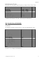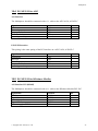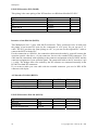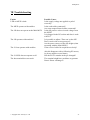
1
Bedienungsanleitung
Multiplexer für
Siemens S5
Bosch
Mitsubishi
AEG
Klöckner-Moeller
Handbuch
deutsch / englisch
für
PG-MUX-II
und
Mini-MUX
Version 1.5
© Copyright 1993 - 2007 by PI + TIS
Multiplexer
Inhaltsverzeichniss
1 VORWORT ........................................................................................................... 4
2 LEISTUNGSMERKMALE ...................................................................................... 5
2.1 PG-MUX-II FÜR SIEMENS-S5 ................................................................................... 5
2.1.1 ZU BEACHTEN .................................................................................................................... 5
2.2 PG-MUX-II FÜR BOSCH ............................................................................................ 6
2.2.1 ZU BEACHTEN .................................................................................................................... 6
2.3 PG-MUX-II FÜR MITSUBISHI .................................................................................... 7
2.3.1 ZU BEACHTEN .................................................................................................................... 7
2.4 PG-MUX-II FÜR AEG............................................................................................... 8
2.4.1 ZU BEACHTEN: ................................................................................................................... 8
2.5 PG-MUX-II FÜR KLÖCKNER-MOELLER ................................................................... 9
2.5.1 ZU BEACHTEN .................................................................................................................. 10
2.6 MINI-MUX .............................................................................................................. 11
2.6.1 ZU BEACHTEN .................................................................................................................. 11
3 INBETRIEBNAHME ............................................................................................ 12
3.1 ANFORDERUNGEN ................................................................................................... 12
3.2 ANSCHLUß ............................................................................................................... 12
4 FUNKTIONSBESCHREIBUNG .............................................................................. 13
5 OPTIMIERUNG DER GESCHWINDIGKEIT .......................................................... 13
6 EINSCHRÄNKUNGEN ......................................................................................... 14
6.1 PG-MUX-II............................................................................................................. 14
6.2 MINI-MUX .............................................................................................................. 14
2
© Copyright 1993 - 2007 by PI + TIS
Multiplexer
7 STECKERBELEGUNG ......................................................................................... 15
7.1 PG-MUX-II FÜR SIEMENS S5.................................................................................. 15
7.2 PG-MUX-II FÜR BOSCH........................................................................................ 16
7.3 PG-MUX-II FÜR MITSUBISHI .............................................................................. 17
7.4 PG-MUX-II FÜR AEG............................................................................................. 19
7.5 PG-MUX-II FÜR KLÖCKNER-MOELLER .............................................................. 19
7.6 MINI-MUX .............................................................................................................. 21
8 TECHNISCHE DATEN ........................................................................................ 22
9 FEHLERBESEITIGUNG ....................................................................................... 23
© Copyright 1993 - 2007 by PI + TIS
3
Multiplexer
1 Vorwort
Für den allgemeinen Anwendungsbereich gibt es zwei verschiedene Ausführungen:
•
•
•
•
•
•
Mini-MUX für Siemens S5
PG-MUX-II für Siemens S5
PG-MUX-II für Bosch CL200-CL400
PG-MUX-II für Mitsubishi FX, A
PG-MUX-II für AEG A120, A250
PG-MUX-II für Klöckner-Moeller PS-3, PS-4
Die oben genannten PG-MUX-II-Geräte sind speziell für den Serviceeinsatz geeignet, da
diese Geräte in einem robusten Metallgehäuse einfach für den mobilen Einsatz in der
Handhabung sind.
Der Mini-MUX für Siemens S5 ist für eine dauerhafte Verbindung OP / PG / AG gedacht.
In einem industriellen Metallgehäuse (für den Schaltschrank- bzw. Schalttafeleinbau
vorbereitet) ist die gesamte Elektronik integriert. Das Gerät kann direkt an die Schalttafel
befestigt werden.
Die Anschlußmechanik, Pinbelegung und elektrische Daten (Mini-MUX eingeschränkt)
entsprechen der jeweiligen Steuerungsspezifikation, so daß der Anwender direkt und ohne
spezielle Adapter mit den gewohnten Kabel der anzuschließenden Geräte, wie PG's und
Bediengeräte, arbeiten kann.
4
© Copyright 1993 - 2007 by PI + TIS
Multiplexer
2 Leistungsmerkmale
2.1 PG-MUX-II für Siemens-S5
• kompatibel zu allen SIMATIC-S5-Steuerungen
• sofort ONLINE mit beiden Schnittstellen zu der SPS
• mit allen originalen und kompatiblen Programmiergeräten zu betreiben
• alle Anschlüsse 20mA aktiv (auch zur SPS). Alle Komponenten sind wie gewohnt ohne
zusätzliche Adapter anschließbar
• alle Anschlüsse und Bedienungselemente frontseitig
• Geräteüberprüfungsmodul, welches sämtliche Gerätefunktionen und Spannungsversorgung
überprüft und bei einer Störung das Gerät selbstständig neu startet
• Kompaktgerät im Metallgehäuse:
PG-MUX-II: 190 x 110 x 50 mm
• 24V DC oder 230V AC Versorgung
2.1.1 Zu Beachten
Wenn man den L1 Bus parallel zu einem PG betreiben möchte, muß man beachten, daß bei
einem empfangen L1-Protokoll die SPS ein Empfangsbit setzt. Dieses Bit muß man dann
abfragen, damit man das Empfangsregister der SPS auslesen kann. Kommt aber über das PGMUX-Gerät ein PG-Protokoll in die SPS, setzt diese das Bit wieder zurück (die SPS sagt
damit: Das, was gerade reinkam war kein L1-Protokoll). Um sicherzustellen, daß das SPSProgramm erkennt, daß etwas in dem L1-Empfangsfach hinterlegt ist, muß sie das Empfangsbit am besten von verschiedenen Stellen des Programms abfragen, damit es nicht
verpasst wird. Das kann der Fall bei langsamen SPS´en oder bei großen Programmen sein.
Wenn zwei Bedienpulte an das MUX-Gerät angeschlossen werden, müssen beide
unterschiedlich parametrisiert werden, damit beide nicht auf die selben Merker oder DB´s
zeigen, da sonst das SPS-Programm nicht mehr unterscheiden kann, welches Bedienpult nun
was bezwecken wollte.
Bei Bedienpulten sollte man generell ein ´TIME-OUT´ einstellen (falls möglich), denn wenn
ein PG z.B. einen langen DB überträgt, darf das Bedienpult nicht auf TIME-OUT gehen. Gute
Werte liegen bei ca. 3-5 sek.
Arbeitet das Bedienpult mit dem PG-Protokoll, kann es passieren, daß das Bedienpult bei
einem DB-Zugriff direkt adressiert. Wenn man nun diesen Daten-DB verändert und dann
wieder zurückschreibt kann es vorkommen, daß das Bedienpult dies nicht bemerkt und immer
noch auf den alten DB zugreift (das Bedienpult merkt dies nicht). Dies kann auch
vorkommen, wenn man ein FB o.ä. tauscht, da sich die Speicheraufteilung in der SPS ändert.
In diesem Fall kann man die Störungen mit einem Komprimiervorgang beheben (die SPS
organisiert sich frisch).
© Copyright 1993 - 2007 by PI + TIS
5
Multiplexer
2.2 PG-MUX-II für Bosch
• kompatibel zu den Steuerungen CL200, CL300 und CL400
• sofort ONLINE mit beiden Schnittstellen zu der SPS
• mit allen originalen und kompatiblen Programmiergeräten zu betreiben
• Die PG-Anschlüsse sind identisch zu einer Bosch-Steuerung und besitzen TTY-passiv,
TTY-aktiv und V24. Alle Komponenten sind wie gewohnt ohne zusätzliche Adapter
anschließbar
• alle Anschlüsse und Bedienungselemente frontseitig
• Geräteüberprüfungsmodul, welches sämtliche Gerätefunktionen und Spannungsversorgung
überprüft und bei einer Störung das Gerät selbstständig neu startet
• Kompaktgerät im Metallgehäuse:
PG-MUX-II: 190 x 110 x 80 mm
• 24V DC oder 230V AC Versorgung
2.2.1 Zu Beachten
Dieses MUX-Gerät kann mit den Baudraten 9600 Baud und 19200 Baud betrieben werden.
Übertragungsparameter 1 Stop-Bit, 8 Daten-Bits, gerade Parität, die Steuersignale dürfen
nicht abgefragt werden.
Wie diese Parameter eingestellt werden, können Sie aus Ihrem Handbuch über die jeweilige
Zentraleinheit erkennen. Bei der CL200 muß z.B. Schalter S1/1 auf ON und Schalter S1/2 auf
OFF stehen, damit 19200 Baud eingestellt ist. Das Übertragungsformat ist schon fest auf
gerade Parität, 1 Stop-Bit, 8 Datenbits, es sind keine Steuerleitungen vorhanden.
Bei der CL400 muß Schalter 1/1 auf ON (1 Stop-Bit), Schalter 1/2 auf OFF (8 Datenbits),
Schalter 1/3 auf ON (gerade Parität), Schalter 1/4 auf ON (Parität ein), Schalter 1/5, 1/6, 1/7
jeweils auf ON für 19200 Baud, Schalter 1/8 auf OFF (Steuersignale nicht abfragen). Die
Lage der Schalter und deren Funktion sind im Bosch-Zentraleinheit-Handbuch der jeweiligen
Steuerungen konkret beschrieben.
Wenn zwei Bedienpulte an das MUX-Gerät angeschlossen werden, müssen beide
unterschiedlich parametrisiert werden, damit beide nicht auf die selben Merker oder DB´s
zeigen, da sonst das SPS-Programm nicht mehr unterscheiden kann, welches Bedienpult nun
was bezwecken wollte.
Bei Bedienpulten sollte man generell ein ´TIME-OUT´ einstellen (falls möglich), denn wenn
ein PG z.B. einen langen DB überträgt, darf das Bedienpult nicht auf TIME-OUT gehen. Gute
Werte liegen bei ca. 3-5 sek.
6
© Copyright 1993 - 2007 by PI + TIS
Multiplexer
2.3 PG-MUX-II für Mitsubishi
• kompatibel zu den FX- und A-Steuerungen
• sofort ONLINE mit beiden Schnittstellen zu der SPS
• mit allen originalen und kompatiblen Programmiergeräten zu betreiben
• Die PG-Anschlüsse sind identisch zu den FX- und A-Steuerungen. Alle Komponenten sind
wie gewohnt ohne zusätzliche Adapter anschließbar
• alle Anschlüsse und Bedienungselemente frontseitig
• Geräteüberprüfungsmodul, welches sämtliche Gerätefunktionen und Spannungsversorgung
überprüft und bei einer Störung das Gerät selbstständig neu startet
• Kompaktgerät im Metallgehäuse:
PG-MUX-II: 190 x 110 x 80 mm
• 24V DC oder 230V AC Versorgung
2.3.1 Zu Beachten
Bei einigen Bedienpulten für eine Mitsubishi-Steuerung kann es vorkommen, daß das
Bedienpult auf die vereinbarten Merker schreibt, aber das Programmiergerät nicht anzeigt,
was das Bedienpult gerade an diesen Merker verändert hat. Das Bedienpult greift in diesem
Fall über eine direkte Adressierung auf die Steuerung zu. Das PG greift aber auch auf diesen
Bereich zu. Es kommt zu einer Kollosion und die Daten dieser Merker stimmen nicht mehr.
Bei den Bedienpulten MAC 10/12 und MAC 40+ muß man nur ´BR´in Commands einfüllen.
Dieses wurde von Beijer und Mitsubishi getestet und funktioniert hervorragend. Dadurch
greift das Bedienpult indirekt auf die Steuerung zu und verändert die Daten bei einem
gemeinsamen Zugriff nicht mehr.
Wenn zwei Bedienpulte an das MUX-Gerät angeschlossen werden, müssen beide
unterschiedlich parametrisiert werden, damit beide nicht auf die selben Merker oder DB´s
zeigen, da sonst das SPS-Programm nicht mehr unterscheiden kann, welches Bedienpult nun
was bezwecken wollte.
Bei Bedienpulten sollte man generell ein ´TIME-OUT´ einstellen (falls möglich), denn wenn
ein PG z.B. einen langen DB überträgt, darf das Bedienpult nicht auf TIME-OUT gehen. Gute
Werte liegen bei ca. 3-5 sek.
© Copyright 1993 - 2007 by PI + TIS
7
Multiplexer
2.4 PG-MUX-II für AEG
• kompatibel zu den A120- und A250-Steuerungen
• sofort ONLINE mit beiden Schnittstellen zu der SPS
• mit allen originalen und kompatiblen Programmiergeräten zu betreiben
• Die PG-Anschlüsse sind identisch zu den A120- und A250-Steuerungen. Alle
Komponenten sind wie gewohnt ohne zusätzliche Adapter anschließbar
• alle Anschlüsse und Bedienungselemente frontseitig
• Geräteüberprüfungsmodul, welches sämtliche Gerätefunktionen und Spannungsversorgung
überprüft und bei einer Störung das Gerät selbstständig neu startet
• Kompaktgerät im Metallgehäuse:
PG-MUX-II: 190 x 110 x 50 mm
• 24V DC oder 230V AC Versorgung
2.4.1 Zu Beachten:
Der Betrieb mit der A120 und der MICRO AEG (über entsprechende Adapter, nicht die TSX
MICRO) läuft einwandfrei. Bei der A250 kann das PG versuchen die SPS zu Normieren. Bei
der Normierung werden Teile in dem SPS-System umgestellt und die Baudraten verändern
sich auch kurzzeitig. Diese Funktion kann das MUX-Gerät nicht unterstützen, da er immer
einen ´offenen Kanal´ für die zweite Schnittstelle offenhalten muß. Deshalb sollte das
gesamte Übertragen des Programms ohne MUX vollzogen werden, da das PG ewig auf die
SPS-Normierung warten würde.
Wenn zwei Bedienpulte an das MUX-Gerät angeschlossen werden, müssen beide
unterschiedlich parametrisiert werden, damit beide nicht auf die selben Merker oder DB´s
zeigen, da sonst das SPS-Programm nicht mehr unterscheiden kann, welches Bedienpult nun
was bezwecken wollte.
Bei Bedienpulten sollte man generell ein ´TIME-OUT´ einstellen (falls möglich), denn wenn
ein PG z.B. einen langen DB überträgt, darf das Bedienpult nicht auf TIME-OUT gehen. Gute
Werte liegen bei ca. 3-5 sek.
8
© Copyright 1993 - 2007 by PI + TIS
Multiplexer
2.5 PG-MUX-II für Klöckner-Moeller
• kompatibel zu den PS3- und PS4-201 Steuerungen
• sofort ONLINE mit beiden Schnittstellen zu der SPS
• mit allen originalen und kompatiblen Programmiergeräten zu betreiben
• Die PG-Anschlüsse sind identisch zu den PS3- und PS4-Steuerungen. Alle Komponenten
sind wie gewohnt ohne zusätzliche Adapter anschließbar. Bei der PS4 werden alle
benötigten Adapter mitgeliefert
• alle Anschlüsse und Bedienungselemente frontseitig
• Geräteüberprüfungsmodul, welches sämtliche Gerätefunktionen und Spannungsversorgung
überprüft und bei einer Störung das Gerät selbstständig neu startet
• Kompaktgerät im Metallgehäuse:
PG-MUX-II: 190 x 110 x 50 mm
• 24V DC oder 230V AC Versorgung
© Copyright 1993 - 2007 by PI + TIS
9
Multiplexer
2.5.1 Zu Beachten
Bei der PG-Software kann eventuell die Schnittstelle falsch eingestellt sein. Man muß
eventuell die Datei COM.INI dazu verändern oder überprüfen. Irgendwo in dieser Datei steht:
; (Deutsch)
; Baudrate: Geschwindigkeit, mit der SUCOSOFT S30-...
; Daten sendet und empfängt. Zulässige Werte:
; 110, 150, 300, 600, 1200, 2400, 4800, 9600 Baud
; ReceiveTimeout: Zeit, die nach dem Empfang eines Zeichens
;vergehen muß, bevor die Übertragung mit einer
; Fehlermeldung abgebrochen wird. Der Wert dieses
; Parameters muß als Ganzzahl in Sekunden angegeben werden.
...
etliche Zeilen Später:
Baudrate=9600
ReceiveTimeout=1
Diese Werte müssen übereinstimmen!
Für den Anschluss an eine PS4-201 müssen die Kabel selbst erstellt werden, da die
Bedienpulte oftmals nicht die runden DIN-Verbindungen besitzen, sondern Sub-D
Steckverbinder. Das Kabel muß nach dem MUX-Belegungsplan und nach dem BedienpultBelegungsplan erstellt werden. Das Verbindungskabel zu dem PC ist ein 9 poliges 1:1 Kabel.
Die Brücken, die das Programmiergeräteprogramm voraussetzt, sind schon in dem MUXGerät auf beiden PG-Buchsen eingebaut.
Wenn zwei Bedienpulte an das MUX-Gerät angeschlossen werden, müssen beide
unterschiedlich parametrisiert werden, damit beide nicht auf die selben Merker oder DB´s
zeigen, da sonst das SPS-Programm nicht mehr unterscheiden kann, welches Bedienpult nun
was bezwecken wollte.
Bei Bedienpulten sollte man generell ein ´TIME-OUT´ einstellen (falls möglich), denn wenn
ein PG z.B. einen langen DB überträgt, darf das Bedienpult nicht auf TIME-OUT gehen. Gute
Werte liegen bei ca. 3-5 sek.
10
© Copyright 1993 - 2007 by PI + TIS
Multiplexer
2.6 Mini-MUX
Für den Mini-MUX gelten dieselben Leistungsmerkmale, wie für den PG-MUX-II für
Siemens-S5, aber mit folgenden Einschränkungen:
• nur 24V Versorgungseingang
• nur die AG-Buchse ist eigenständig aktiv
• die OP-Buchse ist komplett passiv und kann L1 Protokoll und ein begrenztes PG-Protokoll
• die PG-Buchse kann nur PG-Protokoll und wird elektrisch gesehen von der SPS versorgt
• kein PG-Bus-Protokoll möglich
Kompaktgerät im Metallgehäuse:
Mini-MUX: 135 x 110 x 50 mm
Die Einschränkungen des Mini-MUX werden im Artikel 6.2 genauer erklärt.
2.6.1 Zu Beachten
Wenn man den L1 Bus parallel zu einem PG betreiben möchte, muß man beachten, daß bei
einem empfangen L1-Protokoll die SPS ein Empfangsbit setzt. Dieses Bit muß man dann
abfragen, damit man das Empfangsregister der SPS auslesen kann. Kommt aber über das PGMUX-Gerät ein PG-Protokoll in die SPS, setzt diese das Bit wieder zurück (die SPS sagt
damit: Das, was gerade reinkam war kein L1-Protokoll). Um sicherzustellen, daß das SPSProgramm erkennt, daß etwas in dem L1-Empfangsfach hinterlegt ist, muß sie das
Empfangsbit am besten von verschiedenen Stellen des Programms abfragen, damit es nicht
verpasst wird. Das kann der Fall bei langsamen SPS´en oder bei großen Programmen
Bei Bedienpulten sollte man generell ein ´TIME-OUT´ einstellen (falls möglich), denn wenn
ein PG z.B. einen langen DB überträgt, darf das Bedienpult nicht auf TIME-OUT gehen. Gute
Werte liegen bei ca. 3-5 sek.
Arbeitet das Bedienpult mit dem PG-Protokoll, kann es passieren, daß das Bedienpult bei
einem DB-Zugriff direkt adressiert. Wenn man nun diesen Daten-DB verändert und dann
wieder zurückschreibt kann es vorkommen, daß das Bedienpult dies nicht bemerkt und immer
noch auf den alten DB zugreift (das Bedienpult merkt dies nicht). Dies kann auch
vorkommen, wenn man ein FB o.ä. tauscht, da sich die Speicheraufteilung in der SPS ändert.
In diesem Fall kann man die Störungen mit einem Komprimiervorgang beheben (die SPS
organisiert sich frisch).
© Copyright 1993 - 2007 by PI + TIS
11
Multiplexer
3 Inbetriebnahme
3.1 Anforderungen
An die Systemumgebung der Multiplexer werden folgende Anforderungen gestellt:
• 230 V Netzspannungsversorgung (nicht Mini-MUX) oder
• 24 V DC mit mindestens 350mA Laststrom
• eine zu dem jeweiligen MUX kompatible Steuerung
3.2 Anschluß
Um einen problemlosen Betrieb mit den MUX-Geräten zu gewährleisten, sollten diese
Geräte an der eigens dafür vorgesehenen Erdungslasche auf Erdpotential gelegt werden.
Um die Multiplex-Geräte in Betrieb zu nehmen, wird das Gerät zuerst mit der
Spannungsversorgung verbunden.
Beim PG-MUX-II kann man wahlweise 24V DC oder 230V AC anschließen. Die normale
Netzspannung wird mit dem mitgelieferten Kaltgerätekabel auf der Frontseite des
Multiplexers angeschlossen. Möchte man aber die im Schaltschrank vorhandene 24V DCVersorgung nützen, so wird diese an der 2poligen Phoenix-Schraubklemme neben dem 230VSpannungsteil angeschlossen.
Die richtige Polarität ist auf dem frontseitigen Etikett mitaufgedruckt. Somit kann der
MUX-II unabhängig von der Umgebung wahlweise mit 24V DC oder 230V AC ohne
irgendwelche Zusätze oder Umbauten betrieben werden.
Beim Mini-MUX hingegen besteht die Versorgung ausschließlich aus 24V DC. Die Polarität
dieser Spannung ist ebenso wie bei PG-MUX-II auf dem Etikett vermerkt.
Über das beim PG-MUX-II mitgelieferte Verbindungskabel (abhängig von dem jeweiligen
Steuerungstyp) wird die SPS mit dem Multiplexer verbunden. Beim Mini-MUX hingegen ist
dieses Verbindungskabel optional erhältlich.
Das Kabel wird auf der PG-Schnittstelle der SPS eingesteckt, und dann mit der AGSchnittstelle des Multiplexers verbunden.
Ab diesem Zeitpunkt stehen dem Anwender zwei gleichrangige Schnittstellen zur Verfügung
(außer Mini-MUX).
12
© Copyright 1993 - 2007 by PI + TIS
Multiplexer
4 Funktionsbeschreibung
Der Multiplexer verfügt über zwei gleichwertige PG-Schnittstellen (Achtung: Beim MiniMUX nur 1 PG- und 1 OP-Schnittstelle). Die Schnittstellen sind AS511- und L1-kompatibel
(bei der Siemens), Buep19/Buep19e (bei Bosch), Sucom A (bei Klöckner-Moeller), KSFunktionen (AEG). Nach Anstecken des Multiplexers ermittelt dieser die nötigen
Identifikationsdaten von der SPS (Slavenummer etc.). Beide Schnittstellen sind jetzt bereit.
An beiden Schnittstellen können alle PG-Funktionen (nicht Mini-MUX) außer "Bearbeite
Kommando" gleichzeitig ausgeführt werden.
Für L1 kann wahlweise eine der beiden PG-Schnittstellen verwendet werden, wobei die
andere für das Programmiergerät oder Geräten mit AS511 zur Verfügung steht.
Bei der normalen MUX-Funktion leuchtet die grüne LED am MUX. Ist diese erloschen, oder
blinkt diese, so ist ein Fehler aufgetreten.
Achtung:
Beim Mini-MUX kann nur auf der OP-Schnittstelle das L1-Protokoll betrieben
werden.
Weitere Einschränkungen des Mini-MUX werden im Artikel 6.2 genauer erklärt.
5 Optimierung der Geschwindigkeit
(nur bei Multiplexer für Siemens-SPS)
Um einen schnelleren Multiplexvorgang zwischen L1 und PG-Mode zu erreichen,
parametriert der Multiplexer beim Erkennen einer L1-Parametrierung das angeschlossene AG
mit einer PG-Nummer. Die PG-Nummer ist gleich der L1-Slavenummer.
Wenn nun während des laufenden Betriebs die S5-Anwender-Software das AG neu
parametriert (z. B. OB21 = Run nach Stop) und dort die PG-Nummer überschreibt, so kann es
beim nächsten PG-Zugriff über den Multiplexer zu einem Zeitüberlauf kommen.
Dieses Problem kann umgangen werden, wenn der S5-Programmierer grundsätzlich eine PGNummer parametriert.
In diesem Fall verläuft der Multiplexvorgang ohne Probleme. Genauso darf während des
Betriebs die L1 Nummer bzw. die PG-Nummer nicht verändert werden, da der Multiplexer
sich diese Nummern nur beim Verbindungsaufbau zwischen MUX und der SPS aus der SPS
holt und nicht registriert wenn diese verändert werden.
Die L1- bzw. PG-Nummer ist im Betriebssystemwort 57 hinterlegt.
Außerdem kann man bei Bedienpulten die Geschwindigkeit dadurch etwas erhöhen, indem
man die für den Betrieb benötigten Merkerworte eng zueinander legt. Der Zugriff geht
schneller, wenn das Bedienpult z.B. geschlossen auf MW 100-103 zugreifen kann und nicht
auf z.B. MW75, dann MW 106, dann MW15 usw.
© Copyright 1993 - 2007 by PI + TIS
13
Multiplexer
6 Einschränkungen
6.1 PG-MUX-II
Für PG-MUX-II für Siemens-S5:
• Der Betrieb mit L1-Protokoll ist nur an einer der beiden PG-Schnittstellen möglich, da es
in einem L1-System nur ein Master gibt
• Der Multiplexer ist der Master bzgl. der SPS
• Der L1-Bus ist als Slaveprotokoll, ohne Interrupt, Broadcast und Querverkehr
implementiert
• "Bearbeite Kommando" wurde und wird auch weiterhin aus Sicherheitsgründen nicht
unterstützt
Für PG-MUX-II für Bosch, Mitsubishi, AEG, Klöckner-Moeller:
• Bei diesen Multiplexertypen gehen zwei Programmiergeräte NICHT gleichzeitig im Status
6.2 Mini-MUX
Die OP-Buchse des Multiplexers ist komplett passiv, das heißt, sie besitzt weder die
Ausgänge 5V und 24V DC, und auch keine 20mA Stromquellen. Auf dieser Schnittstelle sind
rein nur die 4 Übertragungssignalleitungen RxD+ (Pin 9), RxD- (Pin 2), TxD+ (Pin 6) und
TxD- (Pin 7) aufgelegt. Weiterhin ist auch das Übertragungsprotokoll dieser Schnittstelle
eingeschränkt, das heißt, es werden keine höheren Programmiergerätebefehle unterstützt, so
zum Beispiel etwa Baustein übertragen, RUN/STOP, steuern Baustein, ..., da diese
Schnittstelle als reine Bediengeräteschnittstelle konzipiert wurde.
Die PG-Buchse kann alle Funktionen des PG´s verarbeiten (außer: Bearbeite Kommando, PGBUS-Protokoll), kann aber kein L1 Protokoll (benützt kein Programmiergerät). Die PGBuchse des Mini-MUX versorgt sich komplett aus der SPS. Das bedeutet, wenn die SPS
keine 20mA Stromquellen oder keine Spannungen herausgibt, liegen diese auch nicht an der
PG-Buchse an.
14
© Copyright 1993 - 2007 by PI + TIS
Multiplexer
7 Steckerbelegung
7.1 PG-MUX-II für Siemens S5
AG Schnittstelle
Diese Schnittstelle sollte 1:1 mit der SPS verbunden werden, damit der Multiplexer seine
volle Funktion besitzt. Die angegebenen Pins sind in diesem Fall Eingänge des Multiplexer.
Pin 11, 13 ist nicht aufgelegt.
Der PG-MUX-II ist schon an der AG-Buchse intern als aktiver Sender und Empfänger
vorbedrahtet. Deshalb müssen zumindest die Pins 2, 9, 6, 7 1:1 mit der SPS durchverbunden
werden.
Signalname
Externe Masse
Stromversorgung +5V DC
Stromversorgung +24V DC
Interne Masse
Externe Masse
Masse für 24V
Interne Masse
Stromversorgung +5V DC
Interne Masse
Bezeichnung
MEXT
+5V
+24V
Masse
MEXT
Masse
Masse
+5V
Masse
Pin
1
3
4
5
8
10
12
14
15
PG1/PG2-Schnittstelle
Dieses Pining entspricht dem Pining einer PG-Schnittstelle an einer Siemens S5.
Signalname
Externe Masse
Empfangsdaten minus
Stromversorgung +5V DC
Stromversorgung +24V DC
Interne Masse
Sendedaten plus
Sendedaten minus
Externe Masse
Empfangsdaten plus
Masse für 24V
20mA Stromquelle Sender
Interne Masse
20mA Stromquelle Empfänger
Stromversorgung +5V DC
Interne Masse
© Copyright 1993 - 2007 by PI + TIS
Bezeichnung
MEXT
TTY IN+5V
+24V
Masse
TTY OUT+
TTY OUTMEXT
TTY IN+
Masse
I-OUT
Masse
I-OUT
+5V
Masse
Pin
1
2
3
4
5
6
7
8
9
10
11
12
13
14
15
15
Multiplexer
7.2 PG-MUX-II für BOSCH
AG-Schnittstelle
Die Bosch CL200, CL300, CL400 wird AG-Seitig mit RS232 betrieben.
Im Normalfall wird der Multiplexer mit einem 1:1 Kabel an die SPS angeschlossen.
Signalname
Externe Masse
Empfangsdaten
Sendedaten
Datenendgerät bereit
Signalmasse
Übermittlungseinheit bereit
Bezeichnung
Schirm
RxD
TxD
DTR
GND
DSR
Pin
1
2
3
6
7
20
PG1/PG2-Schnittstelle V24
Dieses Pining entspricht dem Pining einer Bosch CL200, CL300, CL400.
Signalname
Externe Masse
Sendedaten
Empfangsdaten
Übermittlungseinheit bereit
Signalmasse
Datenendgerät bereit
Bezeichnung
Schirm
TxD
RxD
DSR
GND
DTR
Pin
1
2
3
6
7
20
PG1/PG2-Schnittstelle TTY passiv
Dieses Pining entspricht dem Pining einer Bosch CL200, CL300, CL400.
Signalname
Externe Masse
Empfangsdaten plus
Empfangsdaten minus
Sendedaten plus
Sendataten minus
Übermittlungseinheit bereit plus
Übermittlungseinheit bereit minus
Datenendgerät bereit plus
Datenendgerät bereit minus
16
Bezeichnung
Schirm
TTY IN+ (RxD+)
TTY IN( RxD-)
TTY OUT+ ( TxD+)
TTY OUT- ( TxD-)
DSR+
DSRRDRCTL+
RDRCTL-
Pin
1
22
12
23
13
11
14
19
16
© Copyright 1993 - 2007 by PI + TIS
Multiplexer
PG1/PG2-Schnittstelle TTY aktiv
Dieses Pining entspricht dem Pining einer Bosch CL200, CL300, CL400.
Signalname
Externe Masse
Empfangsdaten plus
Empfangsdaten minus
Sendedaten plus
Sendataten minus
Übermittlungseinheit bereit plus
Übermittlungseinheit bereit minus
Datenendgerät bereit plus
Datenendgerät bereit minus
Bezeichnung
Schirm
TTY IN+ (RxD+)
TTY IN( RxD-)
TTY OUT+ ( TxD+)
TTY OUT- ( TxD-)
DSR+
DSRRDRCTL+
RDRCTL-
Pin
1
12
24
13
25
14
18
16
21
Für den aktiven Betrieb müssen die Anschlußpins 9 und 10 gebrückt werden.
7.3 PG-MUX-II für MITSUBISHI
AG-Schnittstelle
Dieses Pining ist so ausgelegt, damit der Multiplexer mit einem 1:1 Kabel an einer
Mitsubishi FX, A angeschlossen werden kann.
Signalname
Empfangsdaten plus
Empfangsdaten minus
Sendedaten plus
Sendedaten minus
Sendeanforderung plus
Sendeanforderung minus
Sendebereitschaft plus
Sendebereitschaft minus
Stromversorgung +5VDC Eingang
Stromversorgung +5VDC Eingang
Stromversorgung +5VDC Eingang
Stromversorgung +5VDC Eingang
Interne Masse Eingang
Interne Masse Eingang
Kennung1
Kennung2
Bezeichnung
RxD+
RxDTxD+
TxDRTS+
RTSCTS+
CTS+5V
+5V
+5V
+5V
Masse
Masse
0V
PWE\
Pin
3
16
2
15
4
17
5
18
12
13
24
25
7
8
20
21
Die Pins 20, 21 sind im Multiplexer gebrückt.
© Copyright 1993 - 2007 by PI + TIS
17
Multiplexer
PG1/PG2-Schnittstelle
Dieses Pining entspricht dem Pining einer Mitsubishi FX, A.
Signalname
Sendedaten plus
Sendedaten minus
Empfangsdaten plus
Empfangsdaten minus
Sendebereitschaft plus
Sendebereitschaft minus
Sendeanforderung plus
Sendeanforderung minus
Stromversorgung +5VDC Ausgang
Stromversorgung +5VDC Ausgang
Stromversorgung +5VDC Ausgang
Stromversorgung +5VDC Ausgang
Interne Masse Ausgang
Interne Masse Ausgang
Kennung1
Kennung2
18
Bezeichnung
TxD+
TxDRxD+
RxDCTS+
CTSRTS+
RTS+5V
+5V
+5V
+5V
Masse
Masse
0V
PWE\
Pin
3
16
2
15
4
17
5
18
12
13
24
25
7
8
20
21
© Copyright 1993 - 2007 by PI + TIS
Multiplexer
7.4 PG-MUX-II für AEG
AG-Schnittstelle
Dieses Pining ist so ausgelegt, damit der Multiplexer mit einem 1:1 Kabel an einer
AEG A120, A250 angeschlossen werden kann.
Signalname
Empfangsdaten plus
Sendedaten plus
Sendeanforderung plus
Sendebereitschaft plus
Interne Masse Eingang
Bezeichnung
RxD
TxD
RTS
CTS
Masse
Pin
2
3
7
8
5
PG1/PG2-Schnittstelle
Dieses Pining entspricht dem Pining einer AEG A120, A250.
Signalname
Sendedaten
Empfangsdaten
Sendebereitschaft
Sendeanforderung
Interne Masse Ausgang
Bezeichnung
TxD
RxD
CTS
RTS
Masse
Pin
2
3
7
8
5
7.5 PG-MUX-II für Klöckner-MOELLER
AG-Schnittstelle PS3 (RS485)
Dieses Pining ist so ausgelegt, damit der Multiplexer mit einem 1:1 Kabel an einer
Klöckner-Moeller PS3 angeschlossen werden kann.
Signalname
Schirm
Signalleitung A
Interne Masse
Signalleitung B
Stromversorgung +5VDC
© Copyright 1993 - 2007 by PI + TIS
Bezeichnung
Schirm
TD/RD+
Masse
TD/RD+5V
Pin
1
3
5
7
9
19
Multiplexer
PG1/PG2-Schnittstelle PS3 (RS485)
Dieses Pining entspricht dem Pining einer Klöckner-Moeller PS3.
Signalname
Schirm
Signalleitung A
0V
Signalleitung B
+5V
Bezeichnung
Schirm
TD/RD+
Masse
TD/RD+
+5V
Pin
1
3
5
7
9
Schnittstellen der PS4-201 (RS232)
Dieser Multiplexer besitzt drei 9polige Sub-D-Steckverbinder. Diese Steckverbinder sind an
den beiden PG-Schnittstellen genauso wie das Gegenstück zu einem PC aufgelegt. So kann
als Verbindung zu einem PC ein 1:1 Kabel benützt werden. Die AG-Steckverbindung ist so
aufgelegt wie ein PC, es kann also das Kabel, welches bis jetzt zur Kopplung PC zu SPS
eingesetzt wurde, hier eingesteckt werden.
Für den Anschluss an eine PS4-201 müssen die Kabel selbst erstellt werden, da die
Bedienpulte oftmals nicht die runden DIN-Verbindungen besitzen, sondern Sub-DSteckverbinder. Das Kabel muß nach dem MUX-Belegungsplan und nach dem BedienpultBelegungsplan erstellt werden. Das Verbindungskabel zu dem PC ist ein 9poliges 1:1 Kabel.
Die Brücken, die das Programmiergeräteprogramm voraussetzt, sind schon in dem MUXGerät auf beiden PG-Buchsen eingebaut.
Falls man sich ein Kabel erstellen möchte, welches einen runden DIN-Verbinder besitzt:
An dem Adapter wird ein 8poliger Stecker DIN 41524 angebracht.
AG Schnittstelle PS4-201 (RS232):
Signalname
Empfangsdaten
Sendedaten
Interne Masse Eingang
Bezeichnung
RxD
TxD
Masse
Pin MUX
2
3
5
DIN-Stecker
5
2
3
Pin MUX
3
2
5
DIN-Buchse
2
5
3
PG1/PG2-Schnittstelle PS4-201 (RS232):
Signalname
Empfangsdaten
Sendedaten
Interne Masse Eingang
20
Bezeichnung
RxD
TxD
Masse
© Copyright 1993 - 2007 by PI + TIS
Multiplexer
7.6 Mini-MUX
AG Schnittstelle
Diese Schnittstelle sollte 1:1 mit der SPS verbunden werden, damit der Multiplexer seine
volle Funktion besitzt. Die angegebenen Pins sind in diesem Fall Eingänge des Multiplexer.
Der MiniMUX ist schon an der AG-Buchse intern als aktiver Sender und Empfänger
vorbedrahtet. Deshalb müssen zumindest die Pins 2, 9, 6, 7 1:1 mit der SPS durch verbunden
werden.
Signalname
Externe Masse
Stromversorgung +5V DC
Stromversorgung +24V DC
Interne Masse
Externe Masse
Masse für 24V
20mA Stromquelle Sender Eingang
Interne Masse
20mA Stromquelle Empfänger Eingang
Interne Masse
Bezeichnung
MEXT
+5V
+24V
Masse
MEXT
Masse
I-IN
Masse
I-IN
Masse
Pin
1
3
4
5
8
10
11
12
13
15
PG-Schnittstelle
Dieses Pining entspricht dem Pining einer PG-Schnittstelle an einer Siemens S5
Signalname
Externe Masse
Empfangsdaten minus
Stromversorgung +5V DC
Stromversorgung +24V DC
Interne Masse
Sendedaten plus
Sendedaten minus
Externe Masse
Empfangsdaten plus
Masse für 24V
20mA Stromquelle Sender
Interne Masse
20mA Stromquelle Empfänger
Stromversorgung +5V DC
Interne Masse
© Copyright 1993 - 2007 by PI + TIS
Bezeichnung
MEXT
TTY IN+5V
+24V
Masse
TTY OUT+
TTY OUTMEXT
TTY IN+
Masse
I-OUT
Masse
I-OUT
+5V
Masse
Pin
1
2
3
4
5
6
7
8
9
10
11
12
13
14
15
21
Multiplexer
OP-Schnittstelle
Diese Schnittstelle ist komplett passiv und setzt ein aktives Bedienpult voraus!
Signalname
Externe Masse
Empfangsdaten minus
Sendedaten plus
Sendedaten minus
Externe Masse
Empfangsdaten plus
Bezeichnung
MEXT
TTY INTTY OUT+
TTY OUTMEXT
TTY IN+
Pin
1
2
6
7
8
9
8 Technische Daten
Versorgungsspannung
230V AC, +/-15%, 50-60 Hz (nur bei PG-MUX-II)
24V DC, +40%, -30% (Mini-MUX u. PG-MUX-II)
Leistungsaufnahme
maximal 4 VA
Funktionskontrolle
Spannungs- und Watchdogüberwachung
Betriebstemperatur
5 bis 55 Grad Celsius
Abmessungen
Metallgehäuse
AG-Schnittstelle
TTY/20mA Stromschleife
Multiplexer aktiv, Siemens Steuerung passiv
3m Verbindungskabel im Lieferumfang bei PG-MUX-II (bei
Mini-MUX optional)
PG1 + PG2-Schnittstelle
TTY/20mA Stromschleife
Multiplexer aktiv (bei Mini-MUX nur PG1, versorgt aus SPS)
100 % mechanisch und elektrisch kompatibel (bei Mini-MUX
nur PG1 über SPS, OP ist passiv)
2 x AS511 (PG-Protokoll)
1 x SINEC-L1-Bus
SIMATIC-S5 AG90...AG155
5V und 24V werden von der AG an beide PG-Buchsen durch
geschleift (bei Mini-MUX nur PG1)
22
PG-MUX-II 190 x 110 x 50 mm
Mini-MUX 135 x 110 x 50 mm
© Copyright 1993 - 2007 by PI + TIS
Multiplexer
9
Fehlerbeseitigung
Fehler:
LED auf MUX dunkel
Ein MUX arbeitet mit Störungen
Ein OP läuft nicht am Mini-MUX
Ein OP funktioniert mit Störungen
Ein L1 Bus arbeitet mit Störungen
Ein L1 Bus funktioniert nicht
Die Busklemme funktioniert nicht
© Copyright 1993 - 2007 by PI + TIS
mögliche Ursache:
Ist die Versorgungsspannung nicht korrekt angelegt
oder verpolt?
Erdungskabel angeschlossen?
Ein Kabel außerhalb der Richtlinien angeschlossen?
Ist das OP passiv oder verlangt es eine Spannung vom
MUX ?
Ist es in der PG-Buchse gesteckt und arbeitet es mit
L1?
Kann man am OP ein "Time out" einstellen?
Arbeitet es mit Querprotokoll (bei L1)?
Sind die Stromquellen des OP o.k. (bei Betrieb mit
Mini-MUX)?
Wird das Empfangsbufferbit zu langsam abgefragt
(dieses Bit verschwindet bei einem nachfolgenden PGZugriff, deshalb eventuell mehrfach abfragen)?
Hat sich die PG/L1 Nummer in der SPS verändert?
Die Klemme könnte Probleme bei der 20mAErzeugung haben. Bitte tauschen.
23
Multiplexer
Operating instructions
Multiplexer for
Siemens S5
Bosch
Mitsubishi
AEG
Klöckner-Moeller
Handbook
for
PG-MUX-II
and
Mini-MUX
Version 1.5
24
© Copyright 1993 - 2007 by PI + TIS
Multiplexer
CONTENTS:
10 PREFACE ......................................................................................................... 27
11 FEATURES ................................................................................................... 28
11.1 PG-MUX-II FOR SIEMENS S5................................................................................ 28
11.1.1 TAKE NOTICE .................................................................................................................. 29
11.2 PG-MUX-II FOR BOSCH CL200-CL400 ............................................................... 30
11.2.1 TAKE NOTICE .................................................................................................................. 30
11.3 PG-MUX-II FOR MITSUBISHI FX, A ..................................................................... 31
11.3.1 TAKE NOTICE .................................................................................................................. 31
11.4 PG-MUX-II FOR AEG A120, A250 ...................................................................... 32
11.4.1 TAKE NOTICE .................................................................................................................. 32
11.5 PG-MUX-II FOR KLÖCKNER-MOELLER PS-3, PS-4 ............................................. 33
11.5.1 TAKE NOTICE .................................................................................................................. 34
11.6 MINI-MUX ............................................................................................................ 35
11.6.1 TAKE NOTICE .................................................................................................................. 35
12 INSTALLATION ................................................................................................ 36
12.1 REQUIREMENTS ..................................................................................................... 36
12.2 CONNECTION ......................................................................................................... 36
13 FUNCTIONAL DESCRIPTION ........................................................................... 37
14 OPTIMISATION OF VELOCITY ........................................................................ 37
15 RESTRICTIONS ................................................................................................ 38
15.1 PG-MUX-II........................................................................................................... 38
15.2 MINI-MUX ............................................................................................................ 38
© Copyright 1993 - 2007 by PI + TIS
25
Multiplexer
16 CONNECTOR ASSIGNMENT ............................................................................. 39
16.1 PG-MUX-II FOR SIEMENS S5................................................................................ 39
16.2 PG-MUX-II FOR BOSCH...................................................................................... 40
16.3 PG-MUX-II FOR MITSUBISHI ............................................................................ 41
16.4 PG-MUX-II FOR AEG........................................................................................... 43
16.5 PG-MUX-II FOR KLÖCKNER-MOELLER ............................................................... 43
16.6 MINI-MUX ............................................................................................................ 45
17 TECHNICAL DATA .......................................................................................... 46
18 TROUBLESHOOTING ....................................................................................... 47
26
© Copyright 1993 - 2007 by PI + TIS
Multiplexer
10 Preface
In the general application field, there are two different models:
•
•
•
•
•
•
Mini-MUX for Siemens S5
PG-MUX-II for Siemens S5
PG-MUX-II for Bosch CL200-CL400
PG-MUX-II for Mitsubishi FX, A
PG-MUX-II for AEG A120, A250
PG-MUX-II for Klöckner-Moeller PS-3, PS-4
The Multiplexer for that named controls, briefly PG-MUX-II, is easy to handle because of its
rugged metal casing and is thus especially suitable for the mobile use.
The Mini-Mux is intended for a lasting OP / PG / AG connection.
The complete electronics are integrated in an industrial metal casing (which is prepared for
the mounting of a switchgear cubicle or a switch board). The device can be fastened directly
to the switchboard.
Connection mechanics, pin seizure, and electrical data (Mini-MUX only limited) meet the
respective control specification. Thus, users can work directly and without special adapters
with the normal cables of the devices they want to connect, like for example PGs and control
units.
© Copyright 1993 - 2007 by PI + TIS
27
Multiplexer
11 FEATURES
11.1 PG-MUX-II for Siemens S5
• compatible with all SIMATIC-S5-controls
• immediately ONLINE with both interfaces to the PLC
• can be operated by all original and compatible programming devices
• all connections 20mA active (also to the PLC)
• all connections and operating elements are at the front of the device
• module which controls all the device functions and the voltage supply and which resets the
device in case of failure
• compact device in a metal casing:
PG-MUX-II: 190 x 110 x 50 mm
• 24V DC or 230V AC supply
• easy mounting into the switchboard
28
© Copyright 1993 - 2007 by PI + TIS
Multiplexer
11.1.1 Take notice
If you work with the L1 Bus parallel to a PG, you must know that the PLC sets behind a
received L1-protokoll the receive-bit. You must query this bit to recognise that something is
in the receiver. Then you must clean the receiver. But comes a PG-protocol straight behind
the L1-protokoll, the PLC resets the receive-bit (the PLC says that something comes into the
PLC, but it wasn’t a L1-protokoll). To be sure that the program recognise that something is in
the receiver, you must scan the bit at difference places in the PLC-program. So you can be
sure that you doesn’t miss this bit. That problems can appear, if the PLC is slow or the
programs are very big.
If two operation panels are connected to the PG-MUX, both must be differently
parameterised, in case of that the operation panels haven’t the same FW´s and DB´s. If the
FW´s and DB´s are the same, the PLC can not distinguish from what OP the data was
transferred. That problem doesn’t appears when you use different FW´s and DB´s.
You should generally enter a `time-out` into your OP (if it is possible), because if a PG
transfers a large DB (for example), the OP must wait for the next conversation with the PLC.
If you increase the time-out, the OP waits for a longer time, can’t go into the ´time-out´. A
good time is 3-5 sec.
If the OP works with the PG-Protocol, it can may be that the OP addresses directly by
transferring data into a DB. Now if you make changes with the DB in your PG and transfer it
back into the PLC it can appears that the OP doesn’t recognise that there is a new DB into the
PLC and makes so transfers to the old DB (the old OB isn’t active in the system). To allocate
the PLC-memory, you must compress it (the PLC makes a new organisation of its system
organisation). The OP becomes a new chance to work correctly with the PLC.
© Copyright 1993 - 2007 by PI + TIS
29
Multiplexer
11.2 PG-MUX-II for Bosch CL200-CL400
• compatible with all CL200-CL400-controls
• immediately ONLINE with both interfaces to the plc
• can be operated by all original and compatible programming devices
• all PG connections are the same as a Bosch CL200-CL400 and can be selected as TTYpassive, TTY-active and RS232.
• all connections and operating elements are at the front of the device
• module which controls all the device functions and the voltage supply and which resets the
device in case of failure
• compact device in a metal casing:
PG-MUX-II: 190 x 110 x 80 mm
• 24V DC or 230V AC supply
• easy mounting into the switchboard
11.2.1 Take notice
The PG-MUX for Bosch PLC´s supports baudrates of 9600 baud and 19200 baud. The
communicationparameters must be 1 stop-bit, 8 data-bit, even parity, no handshake-signals
(must be turned off).
How to set these parameters, please read your user manual of the PLC. For the CL200 (for
example) you must set switch S1/1 at ON and switch S1/2 at OFF to get the baudrate of
19200 baud. The communication parameters are set hard at 1 stop-bit, 8 data-bit, even parity,
no handshake-signals.
For the CL400 you must set switch S1/1 at ON (1 stop-bit ) and switch S1/2 at OFF (8
Databits) switch 1/3 at ON (even parity), switch 1/4 at ON (parity on), switch 1/5, 1/6, 1/7 at
ON for 19200 Baud, switch S1/8 at OFF (no handshake-signals). The position of the switches
and their functions were printed in the user manual of the Bosch-Central-Unit.
If two operation panels are connected to the PG-MUX, both must be differently
parameterised, in case of that the operation panels haven’t the same FW´s and DB´s. If the
FW´s and DB´s are the same, the PLC can not distinguish from what OP the data was
transferred. That problem doesn’t appears when you use different FW´s and DB´s.
You should generally enter a `time-out` into your OP (if it is possible), because if a PG
transfer a large DB (for example), the OP must wait for the next conversation with the PLC. If
you increase the time-out, the OP waits for a longer time, can’t go into the ´time-out´. A good
time is 3-5 sec.
30
© Copyright 1993 - 2007 by PI + TIS
Multiplexer
11.3 PG-MUX-II for Mitsubishi FX, A
• compatible with the Mitsubishi FX, A -controls
• immediately ONLINE with both interfaces to the plc
• can be operated by all original and compatible programming devices
• all PG connections are the same as a Mitsubishi FX, A.
• all connections and operating elements are at the front of the device
• module which controls all the device functions and the voltage supply and which resets the
device in case of failure
• compact device in a metal casing:
PG-MUX-II: 190 x 110 x 80 mm
• 24V DC or 230V AC supply
• easy mounting into the switchboard
11.3.1 Take notice
At some operation-panels for a Mitsubishi-PLC it can appears that the OP writes into the
agreed FW, but the PG doesn’t signs this new changes. The cause is that the OP writes with
directly addressing into the PLC. The PG makes changes into this area too. The effect is a
collision of the contents in the FW and the PG shows wrong information’s.
At the operation-panels MAC 10/12 and MAC 40+ must only be entered ´BR´ into
commands. This is tested from Beijer and Mitsubishi and works correctly. The OP makes now
indirectly addressing into the PLC and the PG shows the right entries of the FW´s.
If two operation panels are connected to the PG-MUX, both must be differently
parameterised, in case of that the operation panels haven’t the same FW´s and DB´s. If the
FW´s and DB´s are the same, the PLC can not distinguish from what OP the data was
transferred. That problem doesn’t appears when you use different FW´s and DB´s.
You should generally enter a `time-out` into your OP (if it is possible), because if a PG
transfers a large DB (for example), the OP must wait for the next conversation with the PLC.
If you increase the time-out, the OP waits for a longer time, can’t go into the ´time-out´. A
good time is 3-5 sec.
© Copyright 1993 - 2007 by PI + TIS
31
Multiplexer
11.4 PG-MUX-II for AEG A120, A250
• compatible with the AEG A120, A250-controls
• immediately ONLINE with both interfaces to the plc
• can be operated by all original and compatible programming devices
• all PG connections are the same as a AEG A120, A250
• all connections and operating elements are at the front of the device
• module which controls all the device functions and the voltage supply and which resets the
device in case of failure
• compact device in a metal casing:
PG-MUX-II: 190 x 110 x 50 mm
• 24V DC or 230V AC supply
• easy mounting into the switchboard
11.4.1 Take notice
The usage with a A120 and with a MICRO AEG (with adapters for the MICRO AEG, but not
the TSX MICRO) works correctly. At the work with a A250, the PG can try to conform the
PLC. The PLC make changes inside and works with different baudrates for a short time. The
MUX will may lost the communication, but will find it a few seconds later. The PG will show
an error message. In fact, please confirm the function load program into the PLC´ without the
MUX.
If two operation panels are connected to the PG-MUX, both must be differently
parameterised, in case of that the operation panels haven’t the same FW´s and DB´s. If the
FW´s and DB´s are the same, the PLC can not distinguish from what OP the data was
transferred. That problem doesn’t appears when you use different FW´s and DB´s.
You should generally enter a `time-out` into your OP (if it is possible), because if a PG
transfers a large DB (for example), the OP must wait for the next conversation with the PLC.
If you increase the time-out, the OP waits for a longer time, can’t go into the ´time-out´. A
good time is 3-5 sec.
32
© Copyright 1993 - 2007 by PI + TIS
Multiplexer
11.5 PG-MUX-II for Klöckner-Moeller PS-3, PS-4
• compatible with the Klöckner-Moeller PS-3, PS-4-controls
• immediately ONLINE with both interfaces to the plc
• can be operated by all original and compatible programming devices
• all PG connections are the same as a Klöckner-Moeller PS-3, PS-4
• all connections and operating elements are at the front of the device
• module which controls all the device functions and the voltage supply and which resets the
device in case of failure
• compact device in a metal casing:
PG-MUX-II: 190 x 110 x 50 mm
• 24V DC or 230V AC supply
• easy mounting into the switchboard
© Copyright 1993 - 2007 by PI + TIS
33
Multiplexer
11.5.1 Take notice
At the PG-software, it may possibly occurs that the COM-port of the PC have wrong entries.
You must show into the COM.INI file and check the parameters and may change them.
Anywhere in that file stands:
; (English)
; Baudrate: speed at which SUCOSOFT S30-...
; sends and receives data. Permissible values:
; 110, 150, 300, 600, 1200, 2400, 4800, 9600 baud
; ReceiveTimeout: Time that must elapse after the receipt
; of a character before the transfer is aborted with
; an error message. The value for this parameter
; must be an integer value entered in seconds.
some lines later:
Baudrate=9600
ReceiveTimeout=1
This values must be the same.
For the connection to a PS4-201, the connection cables must be make by yourself, because the
operation panels often have a 9-pin-connector, but not the rounded DIN-connectors. The
cable must be customised with regarding at the connector assignment of the PG-MUX and the
connector assignment of your operation panel. The connection cable to the PC must be a 9 pol
1:1 cable. The bridges who were needed by the PG-software are connected internally in the
PG-MUX at both PG connectors.
If two operation panels were connected to the PG-MUX, both must be differently configured,
in case of that the operation panels haven’t the same FW´s and DB´s. If the FW´s and DB´s
are the same, the PLC can not distinguish from what OP the data was transferred. That
problem doesn’t appears when you use different FW´s and DB´s.
You should generally enter a `time-out` into your OP (if it is possible), because if a PG
transfers a large DB (for example), the OP must wait for the next conversation with the PLC.
If you increase the time-out, the OP waits for a longer time, can’t go into the ´time-out´. A
good time is 3-5 sec.
34
© Copyright 1993 - 2007 by PI + TIS
Multiplexer
11.6 Mini-MUX
The Mini-MUX has the same features but with the following restrictions:
• the input of supply is only 24V
• only the AG-socket is independently active
• the OP-socket is completely passive and can L1-protocol and a limited PG-protocol
• the PG-socket only can PG-protocol and is supplied by the plc as far as the electric is
• concerned
• PG-bus-protocol is impossible
• compact device in a metal casing:
Mini-MUX: 135 x 110 x 50 mm
The Mini-MUX´s restrictions are explained in further detail his chapter.
11.6.1 Take notice
If you work with the L1 Bus parallel to a PG, you must know that the PLC sets behind a
received L1-protokoll the receive-bit. You must query this bit to recognise that something is
in the receiver. Then you must clean the receiver. But comes a PG-protocol straight behind
the L1-protokoll, the PLC resets the receive-bit (the PLC says that something comes into the
PLC, but it wasn’t a L1-protokoll). To be sure that the program recognise that something is
into the receiver, you must scan the bit at difference places in the PLC-program. So you can
be sure that you doesn’t miss this bit. That problems can appear, if the PLC is slow or the
programs are very big.
You should generally enter a `time-out` into your OP (if it is possible), because if a PG
transfers a large DB (for example), the OP must wait for the next conversation with the PLC.
If you increase the time-out, the OP waits for a longer time, can’t go into the ´time-out´. A
good time is 3-5 sec.
If the OP works with the PG-Protocol, it can may be that the OP addresses directly by
transferring data into a DB. Now if you make changes with the DB in your PG and transfer it
back into the PLC it can appears that the OP doesn’t recognise that there is a new DB into the
PLC and makes so transfers to the old DB (the old OB isn’t active in the system). To allocate
the PLC-memory, you must compress it (the PLC makes a new organisation of its system
organisation). The OP becomes a new chance to work correctly with the PLC.
© Copyright 1993 - 2007 by PI + TIS
35
Multiplexer
12 Installation
12.1 Requirements
The following restrictions are demanded for the system environment of the Multiplexer:
• 230V line voltage supply (not Mini-MUX) or
• 24V DC with at least 350mA load current
• A PLC and/or a compatible programming device
12.2 Connection
To guarantee a service without problems, please lay these devices at the earthing
terminal (which is exclusively designed for that) on earth potential!
In order to put the Multiplexers into service, they have to be connected with the voltage
supply.
You can connect the PG-MUX-II either to 24V DC or 230V AC. The normal line voltage is
connected to the Multiplexer via a cable (which is delivered with the device) at the front of
the Multiplexer. If you want to use the 24V DC supply (which is in the switchboard), you
must connect it to the green Phoenix-screw terminal next to the 230V voltage part.
The right polarity is printed on the front label. Thus, the MUX-II can be operated
independently of its environment with either 24V DCC or 230V AC without any additional
appliances.
The Mini-MUX, however, can only be operated with 24V DC. The polarity of this voltage is
written down on the label as well.
The connection cable (fifteen-pin, fed through 1to1 of course for the Siemens-control) which
is delivered with the PG-MUX-II connects the AG with the Multiplexer. This connection
cable is optionally available for the Mini-MUX.
The cable is plugged in on the PG-interface of the plc and is then connected to the AGinterface of the Multiplexer.
From now on, users have two equivalent interfaces at their disposal (except Mini-MUX).
36
© Copyright 1993 - 2007 by PI + TIS
Multiplexer
13 Functional Description
The Multiplexer has two equivalent PG-interfaces (Caution: The Mini-MUX only has one
PG- and one OP- interface). These interfaces are AS511- and L1- compatible (Siemens),
Buep19/Buep19e (Bosch), Sucom A (Klöckner-Moeller), KS-functions (AEG).. After
connecting the Multiplexer, it ascertains the necessary identification data of the PLC (slave
number, etc.). Both interfaces are now ready. All PG-functions (not Mini-MUX) except
“Process Command“ can be executed simultaneously at both interfaces.
Either of the two interfaces can be used alternatively for L1. Then, the other interface is
available to the programming device or to devices with AS511.
If the MUX works normally, the green LED at the MUX shines. If this light does not shine
anymore or if it flashes, a defect has occurred.
Caution:
As far as the Mini-MUX is concerned, the L1-protocol can only be operated
on the OP-interface.
Further restrictions of the Mini-MUX are explained in chapter 6.2.
14 Optimisation of Velocity
- only for the Multiplexers for Siemens-S5 In order to achieve a faster Multiplex process between L1 and PG-mode, the Multiplexer sets
parameter values with a PG-number to the connected AG when identifying an L1-parameter
setting. The PG-number is the same as the L1-slave number.
If now during the operation the S5-user-software sets new parameter values to the AG (for
example OB21=Run after Stop) and thus overwrites the PG-number there, a time overflow
may occur when the PG is accessed the next time via the Multiplexer.
This problem can be avoided if the S5 programmer always sets parameter vales to a PGnumber. In this case, the Multiplex proceedings take place without any problems.
It has to be avoided that the L1-number or the PG-number respectively are changed during the
operation since the Multiplexer gets these numbers from the plc only when the connection
between the MUX and the plc is established. Thus, the Multiplexer does not recognise it if
these numbers have been changed.
The L1- or the PG-number respectively are deposited in word 57 of the operating system.
© Copyright 1993 - 2007 by PI + TIS
37
Multiplexer
15 Restrictions
15.1 PG-MUX-II
For PG-MUX-II for Siemens-S5:
The operation with L1-protocol is possible only at either of the two PG-interfaces since
there is only one master in an L1-system.
The Multiplexer is the master with reference to the plc.
The L1-bus is implemented as a slave protocol without interrupt, broadcast, and internet
traffic
In the interest of safety, “Process Command“ has not been and will not be supported.
For PG-MUX-II for Bosch, Mitsubishi, AEG, Klöckner-Moeller:
At this Multiplexer´s does not work two times status at two PG´s
15.2 Mini-MUX
The OP-socket of the Multiplexer is completely passive, i.e. it has neither 5V and 24V DC
exits nor 20mA source of current. Only the four transmission signal lines RxT+ (pin 9), RxD(pin 2), TxD+ (pin 6), TxD- (pin 7) are allocated on this interface. Moreover, the
communication protocol of this interface is restricted, i.e. higher commands for programming
devices are not supported, like for example transfer module, RUN/STOP, control module, ...,
because this interface has been designed simply as the interface of a control unit.
The PG-socket can process all functions of the PG (exception: Process Command, PG-BUSprotocol), but it cannot L1-protocol (it does not use a programming device). The PG-socket of
the Mini-MUX gets its supply completely out of the plc. Thus, if the plc does not give out any
20mA sources of supply or voltages, consequently those cannot cling to the PG-socket.
38
© Copyright 1993 - 2007 by PI + TIS
Multiplexer
16 Connector assignment
16.1 PG-MUX-II for Siemens S5
AG Interface
This Interface should be 1:1 connected with the Siemens-PLC, for a correct work of the
Multiplexer.
The pins below this text are inputs of the Multiplexer.
Pin 11, 13 are not connected.
The PG-MUX-II have internally connected active receiver and transmitter. The pins 2, 9, 6, 7
must be connected 1:1 with the PLC.
Signalname
Internal ground
Current supply +5V DC
Current supply +24V DC
Internal ground
External ground
Ground für 24V
Internal ground
Current supply +5V DC
Internal ground
Notation
GEXT
+5V
+24V
Ground
GEXT
Ground
Ground
+5V
Ground
Pin
1
3
4
5
8
10
12
14
15
PG1/PG2-Interface
This pining is the same pining of the PG-Interface on a Siemens S5
Signalname
External ground
Receiver minus
Current supply +5V DC
Current supply +24V DC
Internal ground
Transmitter plus
Transmitter minus
External ground
Receiver plus
Ground for 24V
20mA current source
Internal ground
20mA current source
Current supply +5V DC
Internal ground
© Copyright 1993 - 2007 by PI + TIS
Notation
GEXT
TTY IN+5V
+24V
Ground
TTY OUT+
TTY OUTGEXT
TTY IN+
Ground
I-IN
Ground
I-IN
+5V
Ground
Pin
1
2
3
4
5
6
7
8
9
10
11
12
13
14
15
39
Multiplexer
16.2 PG-MUX-II for BOSCH
AG-Interface
The Bosch CL200, CL300, CL400 works to the PLC withRS232.
The Multiplexer should be connected with a 1:1 cable to the PLC.
Signalname
External ground
Receiver
Transmitter
Data Terminal Ready
SignalGround
Data Set Ready
Notation
Shield
RxD
TxD
DTR
GND
DSR
Pin
1
2
3
6
7
20
PG1/PG2-Interface V24
This pining is the same pining of the PG-Interface on a Bosch CL200, CL300, CL400.
Signalname
External ground
Transmitter
Receiver
Data Set Ready
SignalGround
Data Terminal Ready
Notation
Shield
TxD
RxD
DSR
GND
DTR
Pin
1
2
3
6
7
20
PG1/PG2-Interface TTY passiv
This pining is the same pining of the PG-Interface on a Bosch CL200, CL300, CL400.
Signalname
External ground
Receiver plus
Receiver minus
Transmitter plus
Transmitter minus
Data Set Ready plus
Data Set Ready minus
Data Terminal Ready plus
Data Terminal Ready minus
40
Notation
Shield
TTY IN+ (RxD+)
TTY IN( RxD-)
TTY OUT+ ( TxD+)
TTY OUT- ( TxD-)
DSR+
DSRRDRCTL+
RDRCTL-
Pin
1
22
12
23
13
11
14
19
16
© Copyright 1993 - 2007 by PI + TIS
Multiplexer
PG1/PG2-Interface TTY aktiv
This pining is the same pining of the PG-Interface on a Bosch CL200, CL300, CL400.
Signalname
External ground
Receiver plus
Receiver minus
Transmitter plus
Transmitter minus
Data Set Ready plus
Data Set Ready minus
Data Terminal Ready plus
Data Terminal Ready minus
Notation
Shield
TTY IN+ (RxD+)
TTY IN( RxD-)
TTY OUT+ ( TxD+)
TTY OUT- ( TxD-)
DSR+
DSRRDRCTL+
RDRCTL-
Pin
1
12
24
13
25
14
18
16
21
To make PG1/PG2-Interface TTY aktiv, connect the pin 9 with the pin 10.
16.3 PG-MUX-II for MITSUBISHI
AG-Interface
The Multiplexer should be connected with a 1:1 cable to the Mitsubishi FX, A PLC.
Signalname
Receiver plus
Receiver minus
Transmitter plus
Transmitter minus
Request To Send plus
Request To Send minus
Clear To Send plus
Clear To Send minus
Current supply +5VDC input
Current supply +5VDC input
Current supply +5VDC input
Current supply +5VDC input
Internal ground input
Internal ground input
Ident1
Ident2
Notation
RxD+
RxDTxD+
TxDRTS+
RTSCTS+
CTS+5V
+5V
+5V
+5V
Ground
Ground
0V
PWE\
Pin
3
16
2
15
4
17
5
18
12
13
24
25
7
8
20
21
The pins 20, 21 are bridged in the Multiplexer.
© Copyright 1993 - 2007 by PI + TIS
41
Multiplexer
PG1/PG2-Interface
This pining is the same pining of the PG-Interface on a Mitsubishi FX, A PLC.
Signalname
Transmitter plus
Transmitter minus
Receiver plus
Receiver minus
Clear To Send plus
Clear To Send minus
Request To Send plus
Request To Send minus
Current supply +5VDC output
Current supply +5VDC output
Current supply +5VDC output
Current supply +5VDC output
Internal ground output
Internal ground output
Ident1
Ident2
42
Notation
TxD+
TxDRxD+
RxDCTS+
CTSRTS+
RTS+5V
+5V
+5V
+5V
Ground
Ground
0V
PWE\
Pin
3
16
2
15
4
17
5
18
12
13
24
25
7
8
20
21
© Copyright 1993 - 2007 by PI + TIS
Multiplexer
16.4 PG-MUX-II for AEG
AG-Interface
The Multiplexer should be connected with a 1:1 cable to the AEG A120, A250 PLC
Signalname
Receiver
Transmitter
Request To Send
Clear To Send
Internal ground input
Notation
RxD
TxD
RTS
CTS
Ground
Pin
2
3
7
8
5
PG1/PG2-Interface
This pining is the same pining of the PG-Interface on a AEG A120, A250 PLC
Signalname
Transmitter
Receiver
Clear To Send
Request To Send
Internal ground output
Notation
TxD
RxD
CTS
RTS
Ground
Pin
2
3
7
8
5
16.5 PG-MUX-II for Klöckner-Moeller
AG-Interface PS3 (RS485)
The Multiplexer should be connected with a 1:1 cable to the Klöckner-Moeller PS3 PLC
Signalname
Shield
Signal line A
Internal ground
Signal line B
Current supply +5VDC
© Copyright 1993 - 2007 by PI + TIS
Notation
Shield
TD/RD+
Ground
TD/RD+5V
Pin
1
3
5
7
9
43
Multiplexer
PG1/PG2-Interface PS3 (RS485)
This pining is the same pining of the PG-Interface on a Klöckner-Moeller PS3-PLC.
Signalname
Shield
Signal line A
0V
Signal line B
+5V
Notation
Shield
TD/RD+
Ground
TD/RD+
+5V
Pin
1
3
5
7
9
Interface of the PS4-201 (RS232)
This Multiplexer have 3 ports with Sub-D-connectors. These connectors have at both ports
the pining of an inverted PC-port (its the counterpart of a PC-port). So you can use a 1:1
cable. The PLC port have the same pining as a PC, so you can use the original PLC cable to
connect the MUX with the PLC.
For the connection to a PS4-201, the connection cables must be make by yourself, because the
operation panels often have a 9-pin-connector, but not the rounded DIN-connectors. The
cable must be customised with regarding at the connector assignment of the PG-MUX and the
connector assignment of your operation panel. The connection cable to the PC must be a 9 pol
1:1 cable. The bridges who were needed by the PG-software are connected internally in the
PG-MUX at both PG connectors.
If you want to make you own cable with the rounded connector ,you need a DIN 41524
connector with 8 pins.
AG Interface PS4-201 (RS232):
Signalname
Receiver
Transmitter
Internal ground input
Notation
RxD
TxD
Ground
Pin MUX
2
3
5
DIN male plug
5
2
3
Pin MUX
3
2
5
DIN fem. plug
2
5
3
PG1/PG2-Interface PS4-201 (RS232):
Signalname
Receiver
Transmitter
Internal ground input
44
Notation
RxD
TxD
Ground
© Copyright 1993 - 2007 by PI + TIS
Multiplexer
16.6 Mini-MUX
AG Interface
This Interface should be 1:1 connected with the Siemens-PLC, for a correct work of the
Multiplexer.
The pins below this text are inputs of the multiplexer.
Pin 11, 13 are not connected.
The PG-MUXII have internally connected active receiver and transmitter. The pins 2, 9, 6, 7
must be connected 1:1 with the PLC.
Signalname
External ground
Current supply +5V DC
Current supply +24V DC
Internal ground
External ground
Receiver plus
Ground for 24V
20mA current source input
Internal ground
20mA current source input
Internal ground
Notation
MEXT
+5V
+24V
Ground
MEXT
TTY IN+
Ground
I-IN
Ground
I-IN
Ground
Pin
1
3
4
5
8
9
10
11
12
13
15
PG-Interface
This pining is the same pining of the PG-Interface on a Siemens S5
Signalname
External ground
Receiver minus
Current supply +5V DC
Current supply +24V DC
Internal ground
Transmitter plus
Transmitter minus
External ground
Receiver plus
Ground for 24V
20mA current source
Internal ground
20mA current source
Current supply +5V DC
Internal ground
© Copyright 1993 - 2007 by PI + TIS
Notation
MEXT
TTY IN+5V
+24V
Ground
TTY OUT+
TTY OUTMEXT
TTY IN+
Ground
I-OUT
Ground
I-OUT
+5V
Ground
Pin
1
2
3
4
5
6
7
8
9
10
11
12
13
14
15
45
Multiplexer
OP-Interface
Signalname
External ground
Receiver minus
Transmitter plus
Transmitter minus
External ground
Receiver plus
Notation
MEXT
TTY INTTY OUT+
TTY OUTMEXT
TTY IN+
Pin
1
2
6
7
8
9
17 Technical Data
Supply voltage
230V AC, ±15%, 50-60 Hz (only PG-MUX-II)
24V DC, +40%, -30% (Mini-MUX and PG-MUX-II)
Input
max. 4 VA
Functional control
voltage- and watchdog supervision
Working temperature
5 to 55 degree Celsius
Dimensions
metal casing
AG-interface
TTY/20mA current loop
Multiplexer active, Siemens control passive
3m connection cable delivered with the PG-MUX-II
(optionally available for the Mini-MUX)
PG1 + PG2- interface
TTY/20mA current loop
Multiplexer active (Mini-MUX only PG1, supplied by plc)
100 % mechanically and electrically compatible (Mini-MUX
only PG1 via plc, OP is passive)
2 x AS511 (PG-protocol)
1 x SINEC-L1-Bus
SIMATIC-S5 plc90...plc155
5V and 24V are fed through grinding by the AG to both PGsockets (Mini-MUX only PG1)
46
PG-MUX-II 190 x 110 x 50 mm
Mini-MUX 135 x 110 x 50 mm
© Copyright 1993 - 2007 by PI + TIS
Multiplexer
18 Troubleshooting
Faults:
LED on MUX is dark
The MUX operates with troubles
The OP does not operate at the Mini-MUX
The OP operates with troubles?
The L1-bus operates with troubles
The L1-BUS does not operate at all
The bus terminal does not work
© Copyright 1993 - 2007 by PI + TIS
Possible Cause:
Is the supply voltage not applied or poled
correctly?
Is the earth-cable connected?
Are some unspecificated cables connected?
Is the OP passive or does it need voltage from
the MUX?
Is it plugged in the PG-socket and does it work
with L1?
Is it possible to adjust “Time out“ at the OP?
Does it work with a cross protocol?
Are the power sources of the OP alright (when
operating with the Mini-MUX)?
Is the receive buffer bit enquired too slowly?
(this bit disappears with a following PG-access,
so please enquire several times)
Has the PG/L1-number in the plc changed?
The terminal might have problems to generate
20mA. Please exchange it.
47