1
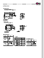
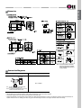
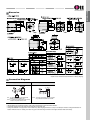
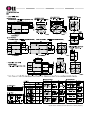
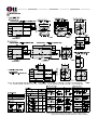
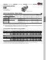
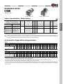
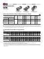
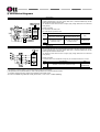
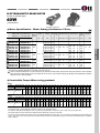
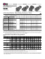
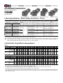
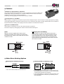
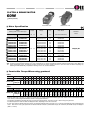
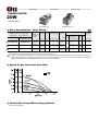
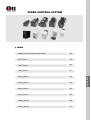
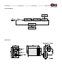
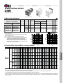
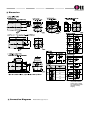
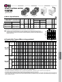
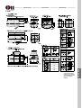
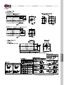
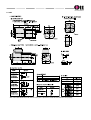
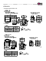
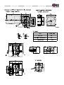
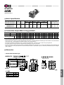
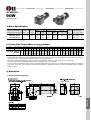
Product Coding System
Motor
9 I D G A
90 F P
A T
Output
6 : 6W
10 : 10W
15 : 15W
25 : 25W
40 : 40W
60 : 60W
Brand
D:
90 : 90W
120 : 120W
150 : 150W
180 : 180W
200 : 200W
Pole
Connection type
A : 2 pole
No mork : 4 pole
T : Terminal Box Type
No mark : Lead Wire Type
Attaching Gearhead Type
G
: General Gearhead (6~60W)
& X 10 Inter-decimal Gearhead
P : Powerful Gearhead (over 60W, 15mm shaft)
H : High Powerful (18mm shaft)
W : Worm Solid type gear
WH : Worm Hollow type gearhead
Shaft Type
G : Pinion Shaft (For GEARHEAD)
S : Round Shaft
D : D-Cut Shaft
K : Key Type Shaft
Phase & Voltage
1 : Single phase 110V 60Hz
2 : Single phase 220V 60Hz
3 : Three phase 220V 60Hz
4 : Three phase 380V 60Hz
5 : Three phase 440V 60Hz
6 : Three phase 220V/380V 60Hz
7 : Three phase 220V/440V 60Hz
A : Single phase 110V 60Hz
B : Single phase 115V 60Hz
C : Single phase 220V 50Hz
D : Single phase 220V 60Hz
E : Single phase 230V 50Hz
F : Single phase 230V 60Hz
G : Three phase 220V 50Hz
H : Three phase 220V 60Hz
I : Three phase 230V 50Hz
J : Three phase 230V 60Hz
K : Three phase 380V 50Hz
L : Three phase 380V 60Hz
M : Three phase 400V 50Hz
N : Three phase 440V 50Hz
O : Three phase 440V 60Hz
P : Three phase 220V/380V 50Hz
Q : Three phase 220V/440V 50Hz
R : Three phase 220V/380V 60Hz
S : Three phase 220V/240V 60Hz
T : Single phase 110V 50Hz
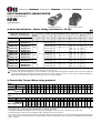
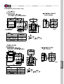
Motor
I
R
S
SR
SB
B
T
CI
CS
V
:
:
:
:
:
:
:
:
:
:
Induction motor
Reversible motor
Speed control motor
Speed control Reversible motor
Speed control Brake motor
Electro magnetic Brake motor
Torque motor
Clutch&brake type Induction motor
Clutch&brake type Speed control motor
Inverter Motor
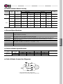
Motor Frame Size
6 : Ū60mm sq. (2.36 in.sq.) (6W)
7 : Ū70mm sq. (2.76 in.sq.) (6~15W)
8 : Ū80mm sq. (3.15 in.sq.) (15~25W)
9 : Ū90mm sq. (3.54 in.sq.) (40~200W)
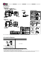
Parallel Gearhead
For Korean
domestic
market
Fan Type
F : General Fan (self cooling)
F2 : Powerful Fan (separate fan motor)
Separate from motor shaft with powrful
cooling effect. Attachment is available in
all kind of motors.
No mark : No fan
For overseas market
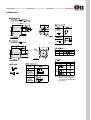
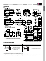
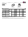
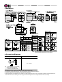
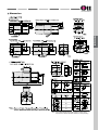
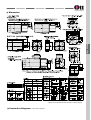
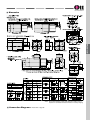
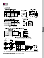
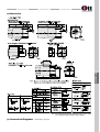
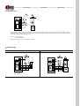
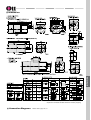
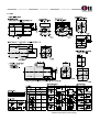
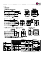
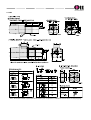
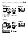
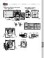
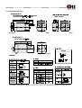
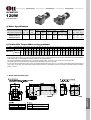
Worm Gearhead
9 P B K 36 B H
Gear Ratio
(36 : 1/36)
9 W D 30 B L
Input Gear Type
Bearing Type
Output Shaft Type
Direction of output
Gear Ratio
(30 : 1/30)
H : Helical Gear
L : Left
R : Right
L/R : Bi-directional
Ţ No mark in Worm
Hollow type
B : Ball Bearing
BM : Ball Bearing + Metal Bearing
M : Metal Bearing
K : Key Type
D : D-cut Type
S : Round Type
Bearing TYPE
B : Ball Bearing
Ţ No mark in Worm Hollow type
Frame Type (G, P, H type gear)
B : Box Type(Square Box type)
F : Flange Type(only available in 'P' type >- '9PF~'
BRAND
D : DKM
Gear Type
G : General Gear (for 6 ~ 40W) (permissible torque : 100Kgfcm)
P : Powerful gear (for 60 ~ 200W) (permissible torque : 200Kgfcm)
H : High powerful gear (for 90~200W) (permissible torque : 300Kgfcm)
Gearhead Type
W : Worm Solid type (6~60W)
WH : Worm Hollow type (60~200W)
Frame Size
Frame Size
6 : Ū60mm sq. (2.36 in.sq.) (6W)
7 : Ū 70mm square (2.76 in.sq.) (6~15W)
8 : Ū 80mm square (3.15 in.sq.) (15~25W)
9 : Ū 90mm square (3.54 in.sq.) (40~200W)
8 : Ū 80mm square (3.15 in.sq.) (15~25W)
9 : Ū 90mm square (3.54 in.sq.) (40~200W)
Ţ Worm Hollow Gearhead is 90mm.
Ţ Ref.
Output
R : Right
L : Left
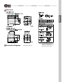
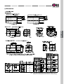
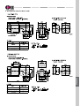
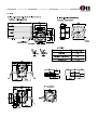
X10 Inter - Decimal Gearhead
9
X
D 10 M
Metal Bearing
D
X10 Inter-Decimal Gearhead
Ŧ
8 : Ū 80mm sq. (3.15 in.sq.) (15~25W)
9 : Ū 90mm sq. (3.54 in.sq.) (40~200W)
Attaching Gearhead
G : General(Helical)
P : Powerful Gearhead
H : High Powerful Gearhead
W : Angle type Worm Gearhead
WH : Worm Hollow type Gearhead
Ratio (10 : 1/10)
Frame Size
H
In case of exceeding 200:1 ratio, please use X10 Inter-decimal gearhead with
general gearhead. And please be advised that in this case only speed will reduce by
10:1 without torque increasing.
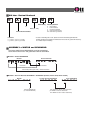
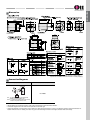
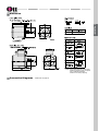
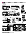
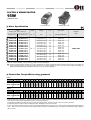
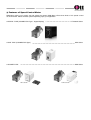
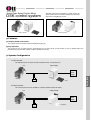
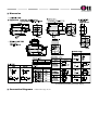
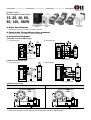
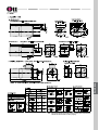
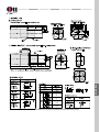
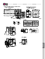
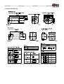
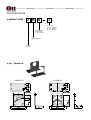
ASSEMBLY of MOTOR and GEARHEAD
Like below MOTOR and GEARHEAD could be assembled.
Same frame size's motor and gearhead could be assembled.
ڣMOTOR + General GEARHEAD
MOTOR
General Gearhead
8 I D G 2 - 25 F G
8 G B K
36 M H
ŭ
General Gearhead
Frame Size
Gear Shaft (Helical gear shaft) + Helical Gearhead
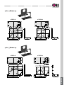
ڤMOTOR + X10 Inter-Decimal GEARHEAD + GEARHEAD (General, Worm Solid, Worm Hollow)
MOTOR
X10 Inter-Decimal GEARHEAD
9 I D G 2 - 60 F G
9 X D 10 M W
Worm GEARHEAD
9 W D 36 B L
ŭ
ŭ
General GEARHEAD
(for X10 GEARHEAD)
X10 Gearhead + Worm Solid Gearhead
('H' MARK for General Gearhead.
'WH' MARK for Worm Hollow Gearhead)
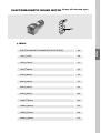
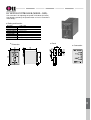
AC Motors
INDUCTION MOTOR ........................................... 15
2POLE MOTOR .................................................... 48
REVERSIBLE MOTOR ......................................... 65
E.M (Electromagnetic) BRAKE MOTOR ............... 87
CLUTHCH & BRAKE MOTOR ……………………. 114
TORQUE MOTOR …………………………………. 129
SPEED CONTROL SYSTEM …………………….. 142
Speed control Reversible Motors ………………………….. 174
Speed control E.M. Brake Motors ………………………….. 181
Speed control C.B. Motors ………………………………… 189
GEARHEAD ………………………………………… 196
DC Motors
DC MOTOR …………………………………………. 216
Accessories
…………………………………………… 233
Extension Cable …………………………………………. 238
Mountin Plate
* Please be informed that the contents could be changed
Without any information for improvement
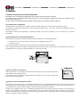
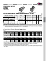
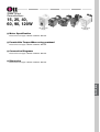
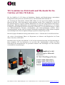
Features of DKM AC Motors
Ŧ
Easy-to-use and Reliable
Just the connection of power supply and capacitor is needed for operating standard compact AC motors. Three-phase motors
do not even require a capacitor. DKM developed small standard AC motors first time in Korea in 1987 so it has high reliability
and service life.
Ŧ
Conform to Safety Standards and Globalization
Many of DKM Motors have CE, TUV, CCC Marking and conform UL/EN standards in accordance with the low voltage directives.
DKM Motors are available in power supply voltages that meet the requirements of the world. (50/60Hz, 100~440VAC)
Ŧ
Variety of Functions
DKM Motors have very various specs ; Induction motors that run continuously and Reversible motors that allow for bi-directional
operation. Additional functionality is available. Electromagnetic brake motors to hold loads in a power-off situation ; Clutch and
brake motors for quick starts and stops ; torque motors for tension control and winding applications. And the combination of
above functions is available.
Ŧ
JIT (Just-In-Time) System
JIT System is available in DKM Motor for the best delivery time. DKM Motor realized userĹs satisfaction with the world best
delivery time.
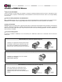
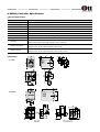
Induction Motors for Continuous operation (Page 15)
Capacitor-run, single-phase and three-phase motors
are available. Lead wire type, terminal box type (TB
type) motors are available. They are depending on
how the power source and the motors are connected.
Lead wire type
Terminal
box type
2 pole Motors (Page 45)
Capacitor-run, single-phase motors are available.
Lead wire type is available.
Rated speed is 3,200 rpm.
Reversible Motors for Bi-directional operation (Page 63)
These are capacitor-run, single-phase motors.
The outward appearance is the same as that of
induction motors. These motors are suited for
applications where the motor must frequently switch
direction.
Lead wire type
Terminal
box type
FEATURES
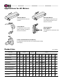
Electromagnetic Brake Motors for load holding (Page 85)
This product is a load-holding brake motor with a power off
activated type electromagnetic brake.
Clutch and Brake Motors for high frequency starting and stop (Page 113)
This motor combines a clutch and brake mechanism with a
induction motor. It is ideal for high frequency start and stop.
Torque Motors (Page 129)
This motor is suitable for controlling tension and
pushing in winding operations. Torque can be set to
any desired level by changing the Input voltage.
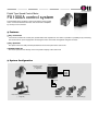
Speed control System (Page 143)
Speed control System allow
you to easily set and adjust
the speed of a motor.
Gearhead (Page 195)
There are 3 kinds of
Gearheads.
; Parallel type, Worm Solid
type and Worm Hollow type.
Parallel type
Worm Solid type
Worm Hollow type
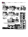
Applications for AC Motors
Induction Motors
Reversible Motors
For uni-directional continuous
operation
For applications where the motor
must switch frequently from one
direction to the next
Torque Motors
Electromagnetic
Brake Motors
For applications where a rolled
object is released according to
the amount of tension.
For applications in which loads must
be held.
Clutch and Brake Motors(C-B Motors)
For applications where the motor must repeat frequent starting
and stopping.
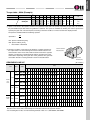
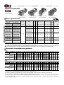
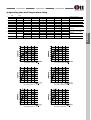
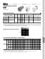
Product Line
Frame Size
Output
( Ŧ = Available )
Ū60 mm
(Ū2.36 in.)
6W
6W
10W
(1/125HP) (1/125HP) (1/75HP)
Ŧ
Ŧ
Reversible Motors
Ŧ
Ŧ
Torque Motors
Ŧ
Electromagnetic Brake Motors
Ŧ
Induction Motors
Ŧ
Clutch and Brake Motors
Speed control Motors
Ŧ
15W
(1/50HP)
15W
(1/50HP)
25W
(1/30HP)
40W
(1/19HP)
60W
(1/12HP)
90W
(1/8HP)
120W
(1/6.25HP)
150W
(1/5HP)
180W
(1/4HP)
200W
(1/3.75HP)
Ŧ
Ŧ
Ŧ
Ŧ
Ŧ
Ŧ
Ŧ
Ŧ
Ŧ
Ŧ
Ŧ
Ŧ
Ŧ
Ŧ
Ŧ
Ŧ
Ŧ
Ŧ
Ŧ
Ŧ(10W)
Ŧ
Ŧ
Ū 90 mm
(Ū 3.54 in.)
Ū 80 mm
(Ū 3.15 in.)
Ū 70 mm
(Ū 2.76 in.)
Ŧ(20W) Ŧ(30W) Ŧ(40W)
Ŧ
Ŧ
Ŧ
Ŧ
Ŧ
Ŧ
Ŧ
Ŧ
Ŧ
Ŧ
Ŧ
Ŧ
Ŧ
Ŧ
Ŧ
Ŧ
Ŧ
Ŧ
Ŧ
Ŧ
Ŧ
Ŧ
Ŧ
Ŧ
Ŧ
Ŧ
Ŧ
Ŧ
Inverter Motors
2 pole Motors
Ŧ
Ŧ
Ŧ
Ŧ
FEATURES
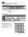
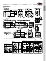
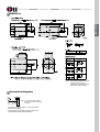
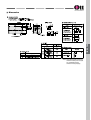
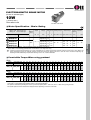
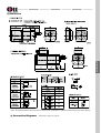
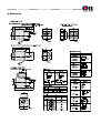
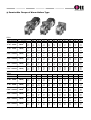
How to Read Motor Specifications
Motor Specifications Table (Example)
Model
Upper Model Name:Pinion Shaft Type
Lower Model Name( ):Round Shaft Type
ώ
Voltage
Freq.
Output Power
Lead Wire Type
Dimension
Terminal Box Type
Dimension
9IDGA-90FP
9IDGA-90FP-T
(9IDSA-90FP)
(9IDSA-90FP-T)
9IDGC-90FP
9IDGC-90FP-T
(9IDSC-90FP)
(9IDSC-90FP-T)
9IDGD-90FP
9IDGD-90FP-T
(9IDSD-90FP)
(9IDSD-90FP-T)
ϒ
Ϗ
ϐ
ϑ
Current
Starting Torque
Rated Torque
Rated
speed
Capacitor
HP
W
VAC
Hz
A
mN.m
gfcm
mN.m
gfcm
r/min
ל
VAC
1/8
90
ĺSingle phase 110
50/60
2.0
4.5
4500
5.7
5700
50Hz:1350
60Hz:1550
20
250
1/8
90
Single phase 220
50/60
1.0
4.5
4500
5.7
5700
50Hz:1350
60Hz:1550
5.0
400
1/8
90
Three phase 220
50/60
0.8
7.0
7000
5.7
5700
50Hz:1350
60Hz:1550
-
-
ώ Output Power : The amount of work that can be performed in a given period of time. It can be used as a criteria for motor capability.
Ϗ Current : The current value used by a motor when the motor is producing rated torque.
ϐ Starting Torque : This term refers to the torque generated the instant the motor starts.
If the motor is subjected to a friction load smaller than this torque, it will operate.
ϑ Rated Torque : This is the torque created when the motor is operating most efficiently. Though the maximum torque is far greater,
rated torque should, from the stanpoint of utility, be the highest torque.
ϒ Rated Speed : This is the speed of the motor when the motor is producing rated torque
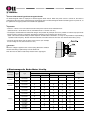
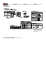
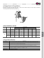
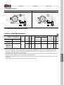
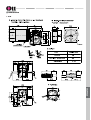
Motor Specifications for Permissible Overhung Load and Permissible Thrust Load
ώ Permissible Overhung Load N (kgf) lb.
Motor
Overhung Load ڣ
Distance from shaft end mm (inch)
Frame Size
Ūmm (inch)
Output Shaft Diameter
٦mm (inch)
60 (2.36)
6 (0.24)
50
(5)
11.2
110
(11)
24.7
70 (2.76)
6 (0.24)
40
(4)
9
60
(6)
13.5
80 (3.15)
8 (0.31)
90
(9)
20
140
(14)
31
10 (0.39)
140
(14)
31
200
(20)
45
12 (0.47)
240
(24)
54
270
(27)
60
20 (0.79)
10 (0.39)
Thrust Load
Ϗ
90 (3.54)
ώ Permissible Overhung Load : The value ڣshown in the table above is the value for the permissible overhung load. As
shown in the figure above, permissible overhung load is the permissible value of the load applied in a direction perpendicular
to the gearhead output shaft.
Ϗ Permissible Thrust Load : As shown in the figure above, this term refers to the permissible value of load applied in the axial
direction to the gearhead ouput shaft. Keep the thrust load to no more than half the motor weight.
The calculating method of overhung load applied on the output shaft is the same as for a gearhead.
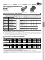
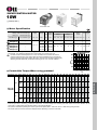
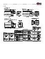
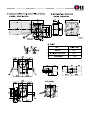
How to Read Gearhead Specifications
Torque table ; 60Hz (Example)
Unit : Upper values : N.m / Middle : kgfcm / Lower : lb-in
Model
speed RPM (r/min)
500
300
200
120
100
60
50
30
20
15
10
Motor/ Gearhead
Gear Ratio
3.6
6
9
15
18
30
36
60
90
120
180
9IDG2-90FP
9PBKŪBH
9PFKŪBH
17
1.7
15
28
2.8
25
41
4.1
36
62
6.2
55
75
7.5
66
112
11.2
99
134
13.4
118
200
20
177
200
20
177
200
20
177
200
20
177
unit
kgfcm
N.m
lb-in
ώ Permissible Torque : It refers to the value of load torque driven by the gearhead's output shaft. Each value is shown for the
corresponding gear ratio.
Permissible torque when a gearhead is connected can be calculated with the equation below.
Permissible Torque
TG = TM X i X n
TG = Permissible Torque of Gearhead
TM = Motor Torque
i = Gear Ratio of Gearhead
n = Gearhead Efficiency
Gearhead Efficiency
Ratio
3
3.6
5
6
7.5
9
10
13
15
18
20
25
30
36
40
50
60
75
90
100
120
150
Model
6GBDŪB(M)H
7GBKŪB(M)H
81%
73%
66%
8GBKŪB(M)H
9GBKŪB(M)H
9PBKŪBH
9PFKŪBH
81%
73%
66%
59%
9HBKŪBH
Ŧ
Ŧ
The efficiency of decimal gearhead is 81%.
In case of worm gearhead, please refer to their pages. (Page 189 )
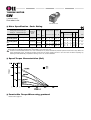
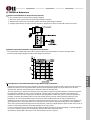
Maximum Permissible Torque
The gearhead output torque increases proportionally as
the gear ratio increases. But, factors affecting the
gearhead mechanical strength such as gear construction
and materials etc., limit size of the load which can be
applied to the gearhead.
This torque is called the maximum permissible torque.
The maximum permissible torques of typical gearheads
are shown in the figure to the right.
Gear Ratio
180
200
250
FEATURES
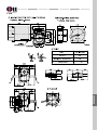
Torque table ; 60Hz (Example)
ώ
Model
Speed RPM (r/min)
500
300
200
120
100
60
50
30
20
15
10
Motor/ Gearhead
Gear Ratio
3.6
6
9
15
18
30
36
60
90
120
180
9IDG2-90FP
9PBKŪBH
9PFKŪBH
17
1.7
15
28
2.8
25
41
4.1
36
62
6.2
55
75
7.5
66
112
11.2
99
134
13.4
118
200
20
177
200
20
177
200
20
177
200
20
177
unit
kgfcm
N.m
lb-in
ώ Speed : This refers to the speed of rotation in the gearhead ouput shaft. The speeds, depending on gear ratio, are shown in
the permissible torque table when the gearhead is attached. The speed is calculated by dividing the motor’s synchronous
speed by the gear ratio. The actual speed, according to the load condition, is 2~20% less than the displayed value.
The speed is calculated with the foollowing equation.
Speed NG =
NM
i
NG : Speed of Gearhead [r/min]
NM : Speed of Motor [r/min]
i : Gear Ration of Gearhead
Ϗ Direction of rotation : This refers to the direction of rotation viewed from
the output shaft. The colored background areas indicate rotation in the
same direction as the motor shaft, while the others rotate in the opposite
direction. The direction of gearhead shaft rotation may differ from motor
shaft rotation depending on the gear ratio of the gearhead. The gear ratio
and rotation direction of each gearhead is shown in the table below.
Counter Clockwise
Direction(CCW)
Clockwise
Direction(CW)
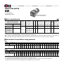
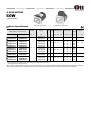
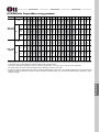
GEARHEAD LINE-UP
( Ŧ = Available )
RATIO
ITEM
WATT
MODEL
2
3 3.6
5
6 7.5
9
10 12.5 15 18 20 25 30 36 40 50 60 75 80 90 100 120 150 180 250 300 360
6GBDŪBMH ʼn Ŧ
Ŧ
Ŧ
Ŧ Ŧ
Ŧ
Ŧ
Ŧ
Ŧ
Ŧ
Ŧ
Ŧ Ŧ Ŧ
Ŧ
Ŧ
Ŧ Ŧ
ʼn Ŧ Ŧ
Ŧ
Ŧ
Ŧ
Ŧ
ʼn
ʼn
6,10 15W 7GBDŪBMH ʼn ʼn
Ŧ
ʼn
Ŧ ʼn
Ŧ
ʼn
Ŧ
Ŧ
Ŧ
ʼn
Ŧ Ŧ Ŧ
Ŧ
Ŧ
Ŧ Ŧ
ʼn Ŧ Ŧ
Ŧ
Ŧ
Ŧ
ʼn
ʼn
ʼn
15, 25W
8GBKŪBMH ʼn ʼn
Ŧ
Ŧ
Ŧ Ŧ
Ŧ
ʼn
Ŧ
Ŧ
Ŧ
ʼn
Ŧ Ŧ Ŧ
Ŧ
Ŧ
Ŧ Ŧ
ʼn Ŧ Ŧ
Ŧ
Ŧ
Ŧ
Ŧ
Ŧ
Ŧ
40W
9GBKŪBMH Ŧ ʼn
Ŧ
Ŧ
Ŧ Ŧ
Ŧ
Ŧ
Ŧ
Ŧ
Ŧ
ʼn
Ŧ Ŧ Ŧ
Ŧ
Ŧ
Ŧ Ŧ
ʼn Ŧ Ŧ
Ŧ
Ŧ
Ŧ
ʼn
ʼn
ʼn
9PBKŪBH
Ŧ ʼn
Ŧ
Ŧ
Ŧ Ŧ
Ŧ
ʼn
Ŧ
Ŧ
Ŧ
Ŧ
Ŧ Ŧ Ŧ
Ŧ
Ŧ
Ŧ Ŧ
ʼn Ŧ Ŧ
Ŧ
Ŧ
Ŧ
ʼn
ʼn
ʼn
9PFKŪBH
Ŧ ʼn
Ŧ
Ŧ
Ŧ Ŧ
Ŧ
ʼn
Ŧ
Ŧ
Ŧ
Ŧ
Ŧ Ŧ Ŧ
Ŧ
Ŧ
Ŧ Ŧ
ʼn Ŧ Ŧ
Ŧ
Ŧ
Ŧ
ʼn
ʼn
ʼn
9HBKŪBH
ʼn ʼn
Ŧ
ʼn
Ŧ ʼn
Ŧ
ʼn
Ŧ
Ŧ
Ŧ
ʼn
Ŧ Ŧ Ŧ
ʼn
Ŧ
Ŧ Ŧ
ʼn Ŧ Ŧ
Ŧ
Ŧ
Ŧ
ʼn
ʼn
ʼn
8/9WDŪBL
ʼn ʼn
ʼn
ʼn
ʼn ʼn
ʼn
Ŧ Ŧ(12) Ŧ
Ŧ
ʼn
Ŧ Ŧ Ŧ
ʼn
Ŧ
Ŧ ʼn
ʼn ʼn ʼn
ʼn
ʼn
ʼn
ʼn
ʼn
ʼn
8/9WDŪBR
ʼn ʼn
ʼn
ʼn
ʼn ʼn
ʼn
Ŧ Ŧ(12) Ŧ
Ŧ
ʼn
Ŧ Ŧ Ŧ
ʼn
Ŧ
Ŧ ʼn
ʼn ʼn ʼn
ʼn
ʼn
ʼn
ʼn
ʼn
ʼn
9WHDŪ
ʼn ʼn
ʼn
ʼn
ʼn Ŧ
ʼn
Ŧ
ʼn
Ŧ
Ŧ Ŧ ʼn
Ŧ
Ŧ
Ŧ ʼn
Ŧ ʼn ʼn
ʼn
ʼn
ʼn
ʼn
ʼn
ʼn
6W
G TYPE
PARRA
LLEL
TYPE
P TYPE 60~200W
H TYPE 90~200W
WORM
TYPE
SOLID
25~60W
HOLLOW 60~200W
ʼn
Ŧ
Ŧ
Enter the gear ratio in the box(Ū) within the model name. A colored background indicates gear shaft rotation in the same
direction as the motor shaft ; white background indicates rotation in the opposite direction.
Ŧ
For exceeding above ratio, use inter-decimal gearhead of ratio 10:1 ; 8XD10BMH, 9XD10BMH.
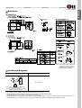
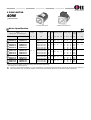
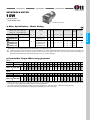
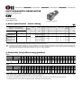
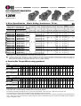
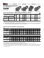
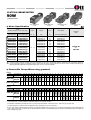
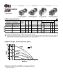
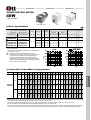
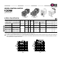
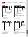
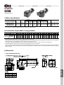
Product Coding System
Motor
9 I D G A
90 F P
Output
6 : 6W
10 : 10W
15 : 15W
25 : 25W
40 : 40W
60 : 60W
Brand
D:
90 : 90W
120 : 120W
150 : 150W
180 : 180W
200 : 200W
A T
Pole
Connection type
A : 2 pole
No mork : 4 pole
T : Terminal Box Type
No mark : Lead Wire Type
Attaching Gearhead Type
G
: General Gearhead (6~60W)
& X 10 Inter-decimal Gearhead
P : Powerful Gearhead (over 60W, 15mm shaft)
H : High Powerful (18mm shaft)
W : Worm Solid type gear
WH : Worm Hollow type gearhead
Shaft Type
G : Pinion Shaft (For GEARHEAD)
S : Round Shaft
D : D-Cut Shaft
K : Key Type Shaft
Phase & Voltage
1 : Single phase 110V 60Hz
2 : Single phase 220V 60Hz
3 : Three phase 220V 60Hz
4 : Three phase 380V 60Hz
5 : Three phase 440V 60Hz
6 : Three phase 220V/380V 60Hz
7 : Three phase 220V/440V 60Hz
A : Single phase 110V 60Hz
B : Single phase 115V 60Hz
C : Single phase 220V 50Hz
D : Single phase 220V 60Hz
E : Single phase 230V 50Hz
F : Single phase 230V 60Hz
G : Three phase 220V 50Hz
H : Three phase 220V 60Hz
I : Three phase 230V 50Hz
J : Three phase 230V 60Hz
K : Three phase 380V 50Hz
L : Three phase 380V 60Hz
M : Three phase 400V 50Hz
N : Three phase 440V 50Hz
O : Three phase 440V 60Hz
P : Three phase 220V/380V 50Hz
Q : Three phase 220V/440V 50Hz
R : Three phase 220V/380V 60Hz
S : Three phase 220V/240V 60Hz
T : Single phase 110V 50Hz
Motor
I
R
S
SR
SB
B
T
CI
CS
V
:
:
:
:
:
:
:
:
:
:
Induction motor
Reversible motor
Speed control motor
Speed control Reversible motor
Speed control Brake motor
Electro magnetic Brake motor
Torque motor
Clutch&brake type Induction motor
Clutch&brake type Speed control motor
Inverter Motor
Motor Frame Size
6 : Ū60mm sq. (2.36 in.sq.) (6W)
7 : Ū70mm sq. (2.76 in.sq.) (6~15W)
8 : Ū80mm sq. (3.15 in.sq.) (15~25W)
9 : Ū90mm sq. (3.54 in.sq.) (40~200W)
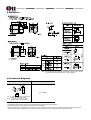
Parallel Gearhead
For Korean
domestic
market
Fan Type
F : General Fan (self cooling)
F2 : Powerful Fan (separate fan motor)
Separate from motor shaft with powrful
cooling effect. Attachment is available in all
kind of motors.
No mark : No fan
For overseas market
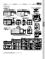
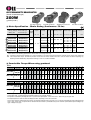
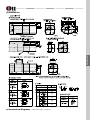
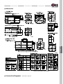
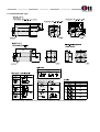
Worm Gearhead
9 P B K 36 B H
Gear Ratio
(36 : 1/36)
9 W D 30 B L
Input Gear Type
Bearing Type
Output Shaft Type
Direction of output
Gear Ratio
(30 : 1/30)
H : Helical Gear
L : Left
R : Right
L/R : Bi-directional
Ţ No mark in Worm
Hollow type
B : Ball Bearing
BM : Ball Bearing + Metal Bearing
M : Metal Bearing
K : Key Type
D : D-cut Type
S : Round Type
Bearing TYPE
B : Ball Bearing
Ţ No mark in Worm Hollow type
Frame Type (G, P, H type gear)
B : Box Type(Square Box type)
F : Flange Type(only available in 'P' type >- '9PF~'
BRAND
D : DKM
Gear Type
G : General Gear (for 6 ~ 40W) (permissible torque : 100Kgfcm)
P : Powerful gear (for 60 ~ 200W) (permissible torque : 200Kgfcm)
H : High powerful gear (for 90~200W) (permissible torque : 300Kgfcm)
Frame Size
6
7
8
9
: Ū 60mm sq. (2.36 in.sq.) (6W)
: Ū 70mm square (2.76 in.sq.) (6~15W)
: Ū 80mm square (3.15 in.sq.) (15~25W)
: Ū 90mm square (3.54 in.sq.) (40~200W)
Gearhead Type
W : Worm Solid type (6~60W)
WH : Worm Hollow type (60~200W)
Frame Size
8 : Ū 80mm square (3.15 in.sq.) (15~25W)
9 : Ū 90mm square (3.54 in.sq.) (40~200W)
Ţ Worm Hollow Gearhead is 90mm.
Ţ Ref.
Output
R : Right
L : Left
FEATURES
X10 Inter - Decimal Gearhead
9
X
D 10 M
Metal Bearing
D
X10 Inter-Decimal Gearhead
Ŧ
8 : Ū 80mm sq. (3.15 in.sq.) (15~25W)
9 : Ū 90mm sq. (3.54 in.sq.) (40~200W)
Attaching Gearhead
G : General(Helical)
P : Powerful Gearhead
H : High Powerful Gearhead
W : Angle type Worm Gearhead
WH: Worm Hollow type Gearhead
Ratio (10 : 1/10)
Frame Size
H
In case of exceeding 200:1 ratio, please use X10 Inter-decimal gearhead with general
gearhead. And please be advised that in this case only speed will reduce by 10:1
without torque increasing.
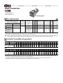
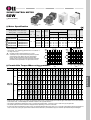
ASSEMBLY of MOTOR and GEARHEAD
Like below MOTOR and GEARHEAD could be assembled.
Same frame size's motor and gearhead could be assembled.
ڣMOTOR + General GEARHEAD
MOTOR
General Gearhead
8 I D G 2 - 25 F G
8 G B K
36 M H
ŭ
General Gearhead
Frame Size
Gear Shaft (Helical gear shaft) + Helical Gearhead
ڤMOTOR + X10 Inter-Decimal GEARHEAD + GEARHEAD (General, Worm Solid, Worm Hollow)
MOTOR
X10 Inter-Decimal GEARHEAD
9 I D G 2 - 60 F G
9 X D 10 M W
Worm GEARHEAD
9 W D 36 B L
ŭ
ŭ
General GEARHEAD
(for X10 GEARHEAD)
X10 Gearhead + Worm Solid Gearhead
('H' MARK for General Gearhead.
'WH' MARK for Worm Hollow Gearhead)
CAUTION FOR USING
Before using, make sure to use it after reading the Instruction Manual closely.
For the suggestions on using, they are classified as caution and warning
CAUTION
WARNING
ҕUse only according to the specifiation of speed controller. If not, there will be dangerous fire, electric shock, iniury and
damage of the unit.
ҕDo not put the fingers or things into the outlet of the unit. There may be the electric shock, injury or danger of fire.
ҕDo not operate with the wet hands. The electric shock may occur.
ҕIn case of moving, do not catch the output shaft, connecting part or the lead wire.There may be the injury by the drop.
ҕMake sure to check whether the things are what you ordered. If you install the other thing, there may occur the injury
and the fire.
ҕThe motor should be used after it is fixed tightly. If not, there may occur the injury and the damage of the unit.
ҕMake sure to install the cover not to touch the rotatory part. If not, there will be injury.
ҕMake sure to check the rotatory direction before connecting the machine. If not, there may occur the injury and the
damage of the unit.
ҕDo not touch the side of the motor output shaft (key way. cutting part) with the naked hands. If not, there may occur
the injury.
ҕMake sure to install the overload device, for the protection device is not attached to the motor.
It is desirable to install the promotion device leakage shorter electricity except the overload protection device.
If not, the fire may occur.
ҕIn case of putting out power plug, do not draw with grasping the plug for the electric shock and fire may occur.
ҕThe motor and the controlling unit should be used only by the designated compounding. If not, the fire may occur.
ҕBefore connecting with the machine and beginning to operate, make sure to install the parameter for the machine.
If not, the damage may take place.
ҕIn case of connecting with the machine and beginning to operate, do in the state of emergency stop anytime.
If not, the damage will occur.
ҕIf there are abnormal cases, turn off the power at once. If not, there will be the electric shock, injury and the damage.
ҕIn operating do not touch the rotor(output shaft). If not, the damage will take place because of winding.
ҕIn operating and right after the operation, do not touch the controlling device by your hands or body. The fire will occur.
ҕNever put around the explosive atmosphere, gas to be burnt, corrosive air, the location to be wet and combustibles.
If not, there may occur the electric shock and the fire.
ҕIn case of movement, connection and checking of motor, please turn off the electric power.
ҕMake sure to connect motor and speed controller based on the specification. If not, there may occur the electric shock
and the fire.
ҕThe power cable and the lead line should not be bent, pulled and inserted by force. If not, the electric shock and the
fire may occur.
ҕIn case the motor and controlling unit are attached to the machine, never touch by hand or connect with the earth. If
not, the electric shock may take place.
ҕNever operate in the state of exposing the flowing current. If not, the electric shock may take place.
ҕIn case of interruption of electric power and wiring the protection of overheat, please turn off the power. When motors
are working continuously, there may be injury and damage of the unti.
ҕWithin the 30 seconds after the power off, do not touch the output terminal of the controlling unit. If not, the electric
shock may occur because of the residual volts.
Lead wire type
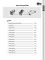
INDUCTION
INDUCTION MOTORS
Terminal Box type
INDEX
INDUCTION MOTOR FEATURES
6W (Ū60mm)
16
17-1
6W (Ū70mm)
18
10W (Ū70mm)
20
15W (Ū70mm)
21-1
15W (Ū80mm)
22
25W (Ū80mm)
24
40W (Ū90mm)
26
60W (Ū90mm)
28
90W (Ū90mm)
31
120W (Ū90mm)
34
150W (Ū90mm)
37
180W (Ū90mm)
40
200W (Ū90mm)
43
Features
Ŧ
Suitable for Uni-directional Continuous Operation
Induction motors are for uni-directional continuous operation such as conveyor belt system.
Ŧ
Meet Safety Standards and Global Power Supply Voltages
The most part of models conform to KS/UL standards and CE Marking. And meets power supply voltages of North America,
Asia and Europe. ; 100V, 110V, 200V, 220V, 230V, 380V, 400V, 440V
Ŧ
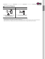
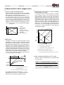
Single Phase run
For a single phase motor run, please use the condenser complying with the capacity of that motor.
For a single-phase induction motor, it is not possible to reverse the direction within a short time during operation.
So stop the motor first and change the direction next. (Figure 1.)
Ŧ
Three Phase run
Three phase induction motor has relative higher starting torque comparing single phase and has high reliability
because it can be operated by a three-phase power source directly. (Figure 2.)
CIRCUIT DIAGRAM(C.W)
SPEED-TORQUE CURVE
CIRCUIT DIAGRAM(C.W)
Figure 1
Ŧ
SPEED-TORQUE CURVE
Figure 2
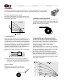
The Relation between Speed and Torque
In a condition of constant power voltage, the relation between speed and torque is like right figure.
Under the condition of no-load, the number of rotation roughly is same as the number of synchronous
rotation. But if the load increases, the number of rotation decreases and approaches to the speed (rpm)
indicated by the point P where the torque Tp horizontally meets the load curve.
When the load further increases and reaches the point M, the motor stops at the point R because the
motor no longer generates further torque.
Therefore, the leg R-M is referred to as an unstable zone and the leg O-M is a stable zone for operation.
Ŧ
Feature of Voltage and Condenser
Generally the torque of induction motor changes in proportion to the value of two times the voltage. And it also changes
according the capacity of the condenser.
If the condenser capacity increases, the starting torque and rated torque will increase.
But if the capacity increases by over 2 times, the rated torque decreases and starting torque do not increase.
When the induction motor is short on torque, it is possible to increase the torque by increasing the voltage or the condenser
capacity to continue the operation.
But please be informed that in this case the loss
input of the motor increases and the rapid rise of
temperature would be. However, if the motor must
be run with insufficient torque, take measures to
let the motor release heat as much as possible by
installing separate fan as a example and operate
the motor so that the temperature of the motor's
housing keep below 90œ .
Power (Voltage)
Frame size
Ūmm (in.)
Output
W
60 (2.36)
6
Page
100/110/115V
200/220/230V
200/220/230V
380 V
440V
Ŧ
Ŧ
-
-
-
17-1
Ŧ
Ŧ
-
-
-
18
Ŧ
Ŧ
-
-
-
20
Ŧ
Ŧ
-
-
-
21-1
15
Ŧ
Ŧ
Ŧ
Ŧ
Ŧ
Ŧ
Ŧ
Ŧ
Ŧ
Ŧ
22
25
Lead Wire
Terminal box
Ŧ
Ŧ
Ŧ
Ŧ
Ŧ
Ŧ
Ŧ
Ŧ
Ŧ
Ŧ
24
40
Lead Wire
Terminal box
Ŧ
Ŧ
Ŧ
Ŧ
Ŧ
Ŧ
Ŧ
Ŧ
Ŧ
Ŧ
26
60
Lead Wire
Terminal box
Ŧ
Ŧ
Ŧ
Ŧ
Ŧ
Ŧ
Ŧ
Ŧ
Ŧ
Ŧ
28
90
Lead Wire
Terminal box
Ŧ
Ŧ
Ŧ
Ŧ
Ŧ
Ŧ
Ŧ
Ŧ
Ŧ
Ŧ
31
120
Lead Wire
Terminal box
Ŧ
Ŧ
Ŧ
Ŧ
Ŧ
Ŧ
Ŧ
Ŧ
Ŧ
Ŧ
34
150
Lead Wire
Terminal box
-
-
Ŧ
Ŧ
Ŧ
Ŧ
Ŧ
Ŧ
37
180
Lead Wire
Terminal box
-
Ŧ
Ŧ
-
-
-
40
200
Lead Wire
Terminal box
-
-
Ŧ
Ŧ
Ŧ
Ŧ
Ŧ
Ŧ
43
10
15
80 (3.15)
90 (3.54)
Three phase
Lead Wire
Lead Wire
Lead Wire
Lead Wire
Lead Wire
Terminal box
6
70 (2.76)
Single phase
Type
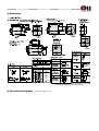
General Specifications
Specifications
Item
Insulation Resistance
100 יor more when 500 VDC is applied between the windings and the frame after rated motor opeation under normal
ambient temperature and humidity.
Dielectric Strength
Sufficient to withstand 1.5 KV at 50 Hz and 60 Hz applied between the windings and the frame for 1 minute after rated
motor operation under normal ambient temperature and humidity.
Temperature Rise
Temperature rise of windings are 80œ (144ǽ) or less measured by the resistance change method after rated motor
operation with connecting a gearhead or equivalent heat radiation plate. [ Three-Phase 6W type : 70œ (126ǽ) ]
Insulation Class
Class B [ 130œ (266ǽ) ]
Overheat Protection
Operating temperature,
open : 130œ ň 5œ (266œ ň9ǽ) close : 82œ ň 15œ (179.6ǽ ň 27ǽ)
Ambient Temperture Range
-10œ ~ + 40œ (14ǽ ~ 104ǽ) [ Three-phase 200VAC : -10œ ~ +50œ (14ǽ ~ 122ǽ) ] (nonfreezing)
Ambient Humidity
85% maximum (noncondensing)
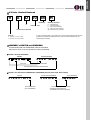
Connection Diagrams
Single phase (CW, CCW)
CWˀTo rotate the motor in a clockwise(CW)
direction, flip switch SW to CW.
CCWˀTo rotate it in a countercloc kwise (CCW)
direction, flip switch SW to CCW.
Three phase (CW, CCW)
CCWˀTo change the rotation direction, change
any connections between U,V and W.
The direction of motor rotation is as viewed from the shaft end of the motor.
CW represents the clockwise direction, while CCW represents the counterclockwise direction.
Ŧ Connection diagrams are also valid for the equivalent round shaft type.
Ŧ Change the direction of single-phase motor rotation only after bringing the motor to a stop. If an attempt is made to change the direction of rotation
while the motor is rotating, the motor may ignore the reversing command or change its direction after some delay.
Ŧ
Ŧ
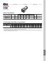
INDUCTION
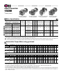
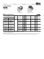
INDUCTION MOTOR LINE-UP
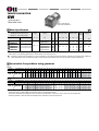
INDUCTION MOTOR
6W
Ū60mm(2.36in.)
LEAD WIRE TYPE
LEAD TYPE MOTOR
+BOX TYPE GEARHEAD
Motor Specification
Model
6IDGŪ-6G : Pinion Shaft Type
6IDGŪ-6 : Round Shaft Type
Lead Wire Type
Output
Terminal Box Type
HP
Voltage
W
Freq. Freq.
VAC
Hz
Rated Torque
Starting Torque
Rated
Speed
A
gfcm
mN.m
oz-in
gfcm mN.m
oz-in
r/min
ל
VAC
0.2
400
40
5.6
400
40
5.8
1550
2.5
250
0.7
400
TP 6IDG(S)A-6G
-
Single Phase110
60
TP 6IDG(S)B-6G
-
Single Phase115
60
TP 6IDG(S)C-6G
-
Single Phase 220
50
490
49
6.9
1300
TP 6IDG(S)D-6G
-
Single Phase 220
60
400
40
5.8
1550
TP 6IDG(S)E-6G
-
Single Phase 230
50
490
49
6.9
1300
TP 6IDG(S)F-6G
-
Single Phase 230
60
400
40
5.8
1550
1/125
6
Capacitor
0.1
400
40
5.6
ҊEnter theĸPhase & VoltageĹcode in the box(Ū) within the motor model name.
ҊĸPinion ShaftĹis for attaching gearhead andĸRound ShaftĹis for using motor only.
TP : Contains a built-in thermal protector. If a motor overheats for any reason the thermal protector opened and the motor stops. When the
motor temperature drops, the thermal protector closes and the motor restarts. Be sure to turn the motor off before inspecting.
Permissible Torque When using gearhead
60Hz
speed RPM (r/min)
Model
Motor/Gearhead
Gear Ratio
6IDGŪ-6G
6GBDŪBMH
600 500 360 300 240 200 180 144 120 100
3
3.6
5
6
7.5
9
10 12.5 15 18
18
15
12
10
9
7.2
90
72
60
50
45
36
30
24
20
20
25
30
36
40
50
60 75
90
100 120 150 180 200 250
24
2.4
21
27
2.7
24
30
3
26
30
3
26
30 30
3 3
26 26
30
3
26
15
12
10
8
6
kgf cm 1.0 1.2 1.7 2.0 2.5 3.0 3.4 4.2 5.0 6.0 6.0 7.5 9.0
N.m 0.10 0.12 0.17 0.20 0.25 0.30 0.34 0.42 0.50 0.60 0.60 0.75 0.89
lb-in 0.88 1.06 1.50 1.77 2.2 2.6 3.0 3.7 4.4 5.3 5.3 6.6 7.9
11 12.5 14 16
1.1 1.2 1.4 1.6
9.7 10.6 12.4 14
20
2.0
18
50Hz
Model
speed RPM (r/min)
Motor/Gearhead
Gear Ratio
6IDGŪ-6G
500 417 300 250 200 166 150 120 100 83
3
3.6
5
6
7.5
9
10 12.5 15 18
75
60
50
41
37
30
25
20
16
20
25
30
36
40
50
60 75
90
13 15
1.3 1.5
11 13
16
1.6
14
19
1.9
17
29
2.9
26
kgf cm 1.2 1.4 2.0 2.4 3.0 3.6 4.0 5.0 6.0 7.1 7.1 8.9 11
6GBDŪBMH N.m 0.12 0.14 0.20 0.24 0.30 0.36 0.40 0.50 0.60 0.71 0.71 0.89 1.1
lb-in 1.06 1.24 1.77 2.1 2.6 3.2 3.5 4.4 5.3 6.3 6.3 7.9 9.7
24
2.4
21
7.5
100 120 150 180 200 250
30
3
26
30
3
26
30
3
26
30 30
3 3
26 26
30
3
26
ҊEnter the gear ratio in the box (Ū) within the gearhead model name. A colored background indicates gear shaft rotation in the same direction
as the motor shaft ; a white background indicates rotation in the opposite direction.
ҊThe speed is calculated by dividing the motor's synchronous speed (50Hz : 1500 r/min, 60 Hz : 1800 r/min) by the gear ratio.
ҊThe actual speed is 2~20% less than the displayed value, depending on the size of the load.
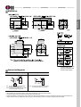
ū Dimension
INDUCTION MOTOR
6W
Ū70mm(2.76in.)
LEAD WIRE TYPE
LEAD WIRE TYPE MOTOR
+BOX TYPE GEARHEAD
Motor Specification
Model
7IDGŪ-6G : Pinion Shaft Type
7IDSŪ-6 : Round Shaft Type
Lead Wire Type
Output
HP
Terminal Box Type
Freq. Freq.
Voltage
W
VAC
Hz
TP 7IDG(S)A-6G
-
Single Phase 110
60
TP 7IDG(S)B-6G
-
Single Phase 115
60
TP 7IDG(S)C-6G
-
Single Phase 220
TP 7IDG(S)D-6G
-
Single Phase 220
TP 7IDG(S)E-6G
-
Single Phase 230
50
TP 7IDG(S)F-6G
-
Single Phase 230
60
1/125
6
Starting Torque
A
Rated Torque
Rated
Speed
Capacitor
gfcm mN.m oz-in gfcm mN.m oz-in
r/min
ל
VAC
400
2.5
250
0.7
400
400
40
5.8
1550
50
490
49
6.9
1350
60
400
40
5.8
1550
490
49
6.9
1350
400
40
5.8
1550
0.25
0.15
40
400
40
5.6
5.6
ҊEnter theĸPhase & VoltageĹcode in the box(Ū) within the motor model name.
ҊĸPinion ShaftĹis for attaching gearhead andĸRound ShaftĹis for using motor only.
TP : Contains a built-in thermal protector. If a motor overheats for any reason the thermal protector opened and the motor stops. When the
motor temperature drops, the thermal protector closes and the motor restarts. Be sure to turn the motor off before inspecting.
Permissible Torque When using gearhead
60Hz
Model
Motor/Gearhead
600
500
360
300
240
200
144
120
100
72
60
50
45
36
30
24
20
3
3.6
5
6
7.5
9
12.5
15
18
25
30
36
40
50
60
75
90
100 120
kgf cm 1.0
0.10
0.88
1.2
0.12
1.06
1.7
0.17
1.50
2.0 2.5
0.20 0.25
1.77 2.2
3.0
0.30
2.6
4.2
0.42
3.7
5.1 6.1
0.50 0.60
4.4 5.3
7.5
0.75
6.6
9.1
0.89
7.9
11
1.1
9.7
12.5
1.2
10.6
14
1.4
12.4
16
1.6
14
20
2.0
18
24
2.4
21
27
2.7
24
500
416
300
250
200
166
120
100
83
60
50
41
38
30
25
20
16
15
3
3.6
5
6
7.5
9
12.5
15
18
25
30
36
40
50
60
75
90
100
3.0
0.30
2.6
3.6
0.36
3.2
5.1
0.50
4.4
6.1
0.60
5.3
7.1
0.71
6.3
8.9
0.89
7.9
11
1.1
9.7
13
1.3
11
15
1.5
13
16
1.6
14
19
1.9
17
24
2.4
21
29
2.9
26
30
3
26
speed RPM (r/min)
Gear Ratio
7IDGŪ-6G 7GBDŪBMH N.m
lb-in
18
15
12
10
150 180
30
3
26
30
3
26
30
3
26
15
10
8.3
50Hz
Model
Motor/Gearhead
speed RPM (r/min)
Gear Ratio
kgf cm
7IDGŪ-6G 7GBDŪBMH N.m
lb-in
1.2 1.4
0.12 0.14
1.06 1.24
2.0 2.4
0.20 0.24
1.77 2.1
120 150 180
30
3
26
30
3
26
30
3
26
ҊEnter the gear ratio in the box (Ū) within the gearhead model name. A colored background indicates gear shaft rotation in the same direction
as the motor shaft ; a white background indicates rotation in the opposite direction.
ҊThe speed is calculated by dividing the motor's synchronous speed (50Hz : 1500 r/min, 60 Hz : 1800 r/min) by the gear ratio.
ҊThe actual speed is 2~20% less than the displayed value, depending on the size of the load.
INDUCTION 6W
Dimension
* NoteˀAbove table indicates output shaft
dimension made by userĹs
request and Ť indicates the basic
dimension in factory shipping.
Connection Diagrams
Single phase (CW, CCW)
Three phase (CW, CCW)
Not Available
CWˀTo rotate the motor in a clockwise(CW)
direction, flip switch SW to CW.
CCWˀTo rotate it in a countercloc kwise (CCW)
direction, flip switch SW to CCW.
Ŧ
Ŧ
Ŧ
Ŧ
The direction of motor rotation is as viewed from the shaft end of the motor.
CW represents the clockwise direction, while CCW represents the counterclockwise direction.
Connection diagrams are also valid for the equivalent round shaft type.
Change the direction of single-phase motor rotation only after bringing the motor to a stop. If an attempt is made to change the direction of
rotation while the motor is rotating, the motor may ignore the reversing command or change its direction after some delay.
INDUCTION MOTOR
10W
Ū70mm(2.76in.)
LEAD WIRE TYPE
LEAD WIRE TYPE MOTOR
+BOX TYPE GEARHEAD
Motor Specification
Model
7IDGŪ-10G : Pinion Shaft Type
7IDSŪ-10 : Round Shaft Type
Output
Lead Wire Type
Terminal Box Type
TP 7IDG(S)A-10G
TP 7IDG(S)B-10G
TP 7IDG(S)C-10G
-
TP 7IDG(S)D-10G
-
TP 7IDG(S)E-10G
TP 7IDG(S)F-10G
HP
Freq. Current Starting Torque
Voltage
VAC
Hz
-
Single Phase 110
60
-
Single Phase 115
60
Single Phase 220
Single Phase 220
-
Single Phase 230
50
-
Single Phase 230
60
W
1/75 10
Rated Torque
Rated
Speed
Capacitor
A
gfcm mN.m oz-in gfcm mN.m oz-in
r/min
ל
VAC
0.3
500
3.0
250
1.0
400
700
70
9.9
1550
50
840
84
11.9
1300
60
700
70
9.9
1550
840
84
11.9
1300
700
70
9.9
1550
0.18
500
50
50
7.1
7.1
ҊEnter theĸPhase & VoltageĹcode in the box(Ū) within the motor model name.
ҊĸPinion ShaftĹis for attaching gearhead andĸRound ShaftĹis for using motor only.
TP : Contains a built-in thermal protector. If a motor overheats for any reason the thermal protector opened and the motor stops. When the
motor temperature drops, the thermal protector closes and the motor restarts. Be sure to turn the motor off before inspecting.
Permissible Torque When using gearhead
60Hz
Model
Motor/Gearhead
speed RPM (r/min)
Gear Ratio
600
500
360
300
240
200
144
120
100
72
60
50
45
36
30
24
20
3
3.6
5
6
7.5
9
12.5
15
18
25
30
36
40
50
60
75
90
9.7
0.97
8.6
12
1.2
10.6
15
1.5
13.2
18
1.8
15.9
20
2.0
17.7
22
2.2
20
26
2.6
23
32
3.2
28
40
4
35
kgf cm 1.5
7IDGŪ-10G
7GBDŪBMH N.m
lb-in
0.15
1.32
1.9 2.5
0.19 0.25
1.68 2.21
3.2
0.32
2.83
4.0
0.40
3.5
4.9 6.7
0.49 0.67
4.3 5.9
8.0
0.80
7.1
500
416
300
250
200
166
120
100
83
60
50
41
38
30
25
20
16
3
3.6
5
6
7.5
9
12.5
15
18
25
30
36
40
50
60
75
90
18
15
12
10
100 120 150 180
40
4
35
40
4
35
40
4
35
40
4
35
15
12.5
10
8.3
50Hz
Model
Motor/Gearhead
speed RPM (r/min)
Gear Ratio
100 120 150 180
2.3
3.0
3.8
4.8
5.9
8.1
9.6
11.6
14
18
22
24
27
31
38
40
40
40
40
7IDGŪ-10G 7GBDŪBMH N.m
0.18
0.23
0.3
0.38
0.48
0.59
0.81 0.96
1.16
1.4
1.8
2.2
2.4
2.7
3.1
3.8
4
4
4
4
4
lb-in
1.59
2.01
2.65
3.39
4.2
5.2
7.1
10.3
12.7
15.9 19.1
21.2
24
28
34
35
35
35
35
35
kgf cm 1.8
8.5
ҊEnter the gear ratio in the box (Ū) within the model name. A colored background indicates gear shaft rotation in the same direction as the
motor shaft ; a white background indicates rotation in the opposite direction.
ҊThe speed is calculated by dividing the motor's synchronous speed (50Hz : 1500 r/min, 60 Hz : 1800 r/min) by the gear ratio.
ҊThe actual speed is 2~20% less than the displayed value, depending on the size of the load.
40
INDUCTION 10W
Dimension
* NoteˀAbove table indicates output shaft
dimension made by userĹs request
and Ť indicates the basic dimension
in factory shipping.
Connection Diagrams
Single phase (CW, CCW)
Three phase (CW, CCW)
Not Available
CWˀTo rotate the motor in a clockwise(CW)
direction, flip switch SW to CW.
CCWˀTo rotate it in a countercloc kwise (CCW)
direction, flip switch SW to CCW.
Ŧ
Ŧ
Ŧ
Ŧ
The direction of motor rotation is as viewed from the shaft end of the motor.
CW represents the clockwise direction, while CCW represents the counterclockwise direction.
Connection diagrams are also valid for the equivalent round shaft type.
Change the direction of single-phase motor rotation only after bringing the motor to a stop. If an attempt is made to change the direction of
rotation while the motor is rotating, the motor may ignore the reversing command or change its direction after some delay.
INDUCTION MOTOR
15W
Ū70mm(2.76in.)
LEAD WIRE TYPE
LEAD TYPE MOTOR
+ BOX TYPE GEARHEAD
Motor Specification
Model
7IDGŪ-15G : Pinion Shaft Type
7IDGŪ-15 : Round Shaft Type
Lead Wire Type
Output
HP
Terminal Box Type
Freq. Current Starting Torque
Voltage
W
VAC
Hz
Rated Torque
A
gfcm
mN.m
oz-in
gfcm mN.m
0.34
650
65
9.2
950
Rated
Speed
oz-in
r/min
ל
VAC
95
13.48
1550
5.0
250
1300
1.2
400
TP 7IDG(S)1-15G
TP 7IDG(S)B-15G
-
Single Phase 110
60
-
Single Phase115
60
TP 7IDG(S)C-15G
-
Single Phase 220
50
700
70
9.9
1120
112
15.9
Single Phase 220
60
650
65
9.2
1000
100
14.2
1550
750
75
10.6 1120
112
15.9
1300
650
65
9.2
100
14.2
1550
1/50
15
TP 7IDG(S)2-15G
TP 7IDG(S)E-15G
-
Single Phase 230
50
TP 7IDG(S)F-15G
-
Single Phase 230
60
0.2
1000
Capacitor
ҊEnter theĸPhase & VoltageĹcode in the box(Ū) within the motor model name.
ҊĸPinion ShaftĹis for attaching gearhead andĸRound ShaftĹis for using motor only.
TP : Contains a built-in thermal protector. If a motor overheats for any reason the thermal protector opened and the motor stops. When the
motor temperature drops, the thermal protector closes and the motor restarts. Be sure to turn the motor off before inspecting.
Permissible Torque When using gearhead
60Hz
Model
Motor/Gearhead
7IDGŪ-7G
speed RPM (r/min)
Gear Ratio
600
500
360
300
240
200
144
120
100
72
60
50
45
36
30
24
20
18
15
12
10
3
3.6
5
6
7.5
9
12.5
15
18
25
30
36
40
50
60
75
90
100
120
150
180
3.1 4.3
0.31 0.43
2.7 3.8
5.1
0.51
4.5
6.4
0.64
5.6
7.7
0.77
6.8
11
1.1
9.7
13
1.3
11
15
1.5
13
19
1.9
17
23
2.3
20
28
2.8
25
31
3.1
27
35
3.5
31
42
4.2
37
50
5
44
50
5
44
50
5
44
50
5
44
50
5
44
50
5
44
500
417
300
250
200
167
120
100
83
60
50
41
37.5
30
25
20
16
15
13
10
8
3
3.6
5
6
7.5
9
12.5
15
18
25
30
36
40
50
60
75
90
100
120
150
180
6.1
0.61
5.4
7.6
0.76
6.7
9.1
0.91
8.0
13
1.30
11
15
1.50
13
18
23
1.80 2.30
16
20
27
2.7
24
33
3.3
29
36
3.6
32
41
4.1
36
50
5
44
50
5
44
50
5
44
50
5
44
50
5
44
50
5
44
50
5
44
kgf cm 2.6
7GBKŪBMH N.m 0.26
lb-in 2.3
50Hz
Model
Motor/Gearhead
7IDGŪ-7G
speed RPM (r/min)
Gear Ratio
kgf cm 3.0
7GBKŪBMH N.m 0.30
lb-in 2.6
3.6 5.1
0.36 0.51
3.2 4.5
ҊEnter the gear ratio in the box (Ū) within the model name. A colored background indicates gear shaft rotation in the same direction as the
motor shaft ; a white background indicates rotation in the opposite direction.
ҊThe speed is calculated by dividing the motor's synchronous speed (50Hz : 1500 r/min, 60 Hz : 1800 r/min) by the gear ratio.
ҊThe actual speed is 2~20% less than the displayed value, depending on the size of the load.
ū Dimension
* NoteˀAbove table indicates output shaft
dimension made by userĹs request
and Ť indicates the basic dimension in
factory shipping.
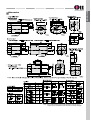
INDUCTION MOTOR
15W
Ū80mm(3.15in.)
LEAD WIRE TYPE MOTOR
+ BOX TYPE GEARHEAD
TERMINAL BOX TYPE MOTOR
+ BOX TYPE GEARHEAD
Motor Specification
Model
8IDGŪ-15G : Pinion Shaft Type
8IDSŪ-15 : Round Shaft Type
Lead Wire Type
Output
HP
Terminal Box Type
Freq. Current Starting Torque
Voltage
W
VAC
Hz
Rated
Speed
Rated Torque
A
gfcm mN.m oz-in gfcm mN.m oz-in
r/min
ל
VAC
0.4
650
65
9.2
950
95
13.48
1550
3.5
250
1.5
400
-
-
TP
8IDG(S)A-15G
8IDG(S)A-15G-T
Single Phase 110
60
TP
8IDG(S)B-15G
8IDG(S)B-15G-T
Single Phase 115
60
TP
8IDG(S)C-15G
8IDG(S)C-15G-T
Single Phase 220
50
700
70
9.9
1120
112
15.9
1300
60
650
65
9.2
1000
100
14.2
1550
750
75
10.6 1120
112
15.9
1300
650
65
9.2
TP
8IDG(S)D-15G
8IDG(S)D-15G-T
Single Phase 220
TP
8IDG(S)E-15G
8IDG(S)E-15G-T
Single Phase 230
50
TP
8IDG(S)F-15G
8IDG(S)F-15G-T
Single Phase 230
60
TP
8IDG(S)G-15G
8IDG(S)G-15G-T
Three Phase 220
50
TP
8IDG(S)H-15G
8IDG(S)H-15G-T
Three Phase 220
60
TP
8IDG(S)I-15G
8IDG(S)i-15G-T
Three Phase 230
50
TP
8IDG(S)J-15G
8IDG(S)J-15G-T
Three Phase 230
60
TP
8IDG(S)K-15G
8IDG(S)K-15G-T
Three Phase 380
50
TP
8IDG(S)L-15G
8IDG(S)L-15G-T
Three Phase 380
60
TP
8IDG(S)M-15G
8IDG(S)M-15G-T
Three Phase 400
50
TP
8IDG(S)N-15G
8IDG(S)N-15G-T
Three Phase 440
50
TP
8IDG(S)O-15G
8IDG(S)O-15G-T
Three Phase 440
60
1/50
15
Capacitor
0.25
0.25
0.14
0.11
1300
130
1300
130
1300
130
1000
100
14.2
1550
1200
120
17
1300
1000
100
14.2
1550
1200
120
17
1300
1000
100
14.2
1550
1200
120
17
1300
1000
100
14.2
1550
1200
120
17
1300
18.5 1000
100
14.2
1550
1000
100
14.2
1550
18.5
18.5
ҊEnter theĸPhase & VoltageĹcode in the box(Ū) within the motor model name.
ҊĸPinion ShaftĹis for attaching gearhead andĸRound ShaftĹis for using motor only.
TP : Contains a built-in thermal protector. If a motor overheats for any reason the thermal protector opened and the motor stops. When the
motor temperature drops, the thermal protector closes and the motor restarts. Be sure to turn the motor off before inspecting.
Permissible Torque When using gearhead
60Hz
Model
Motor/Gearhead
8IDGŪ-15G
speed RPM (r/min)
Gear Ratio
600 500 360 300 240
3
3.6
5
6
7.5
200 144
9
120 100
12.5 15
18
18
12
7
6
5
60
50
45
36
30
24
20
30
36
40
50
60
75
90 100 120 150 180 250 300 360
kgf cm 2.9 3.5 4.9 5.8 7.3 8.7 12.2 14.6 17.5 21.9 26.3 31.5 36.5 39.6 47.5 59.4 71.3 79.2
8GBKŪBMH N.m 0.29 0.35 0.49 0.58 0.73 0.87 1.2 1.5 1.8 2.2 2.6 3.2 3.6 4.0 4.8 5.9 7.1 7.9
28 32 35 42 52 63 70
lb-in 2.6 3.1 4.3 5.1 6.4 7.7 11 13 15 19 23
15
10
72
25
80
8
71
80
8
71
80
8
71
80
8
71
80
8
71
80
8
71
13
10
8
6
5
5
50Hz
Model
Motor/Gearhead
8IDGŪ-15G
speed RPM (r/min)
Gear Ratio
500 417 300 250 200
3
3.6
5
6
7.5
167 120
9
100
83
60
50
42
38
30
25
20
17
12.5 15
18
25
30
36
40
50
60
75
90 100 120 150 180 250 300 360
kgf cm 3.4 4.1 5.7 6.8 8.5 10.2 14.2 17.0 20.4 25.6 30.7 36.8 38.8 46.2 55.4 69.2
8GBKŪBMH N.m 0.34 0.41 0.57 0.68 0.85 1.02 1.4 1.7 2.0 2.6 3.1 3.7 3.8 4.6 5.5 6.9
32 34 41 49 61
lb-in 3.0 3.6 5.0 6.0 7.5 9.0 13 15 18 23 27
80
8
71
15
80
8
71
80
8
71
80
8
71
80
8
71
80
8
71
80
8
71
80
8
71
ҊEnter the gear ratio in the box (Ū) within the model name. A colored background indicates gear shaft rotation in the same direction as the
motor shaft ; a white background indicates rotation in the opposite direction.
ҊThe speed is calculated by dividing the motor's synchronous speed (50Hz : 1500 r/min, 60 Hz : 1800 r/min) by the gear ratio.
ҊThe actual speed is 2~20% less than the displayed value, depending on the size of the load.
ҊIf more slow speed is needed than above value, use decimal gearhead with a gear ratio of 10:1 could be used between general gearhead and
motor. Even in this case, just speed will be reduced without increase in permissible torque; the maximum permissible torque is 80kgfcm
(8N.m, 71lb-in).
INDUCTION 15W
Dimension
* NoteˀAbove table indicates output shaft dimension made by userĹs
request and Ť indicates the basic dimension in factory shipping.
Connection Diagrams
Single phase (CW, CCW)
Three phase (CW, CCW)
Not Available
CWˀTo rotate the motor in a clockwise(CW)
direction, flip switch SW to CW.
CCWˀTo rotate it in a countercloc kwise (CCW)
direction, flip switch SW to CCW.
Ŧ
Ŧ
Ŧ
Ŧ
The direction of motor rotation is as viewed from the shaft end of the motor.
CW represents the clockwise direction, while CCW represents the counterclockwise direction.
Connection diagrams are also valid for the equivalent round shaft type.
Change the direction of single-phase motor rotation only after bringing the motor to a stop. If an attempt is made to change the direction of
rotation while the motor is rotating, the motor may ignore the reversing command or change its direction after some delay.
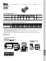
INDUCTION MOTOR
25W
Ū80mm(3.15in.)
LEAD WIRE TYPE MOTOR
+ BOX TYPE GEARHEAD
TERMINAL BOX TYPE MOTOR
+ BOX TYPE GEARHEAD
Motor Specification
Model
8IDGŪ-25G : Pinion Shaft Type
8IDSŪ-25 : Round Shaft Type
Lead Wire Type
Output
HP
Terminal Box Type
Freq. Current Starting Torque
Voltage
W
VAC
Hz
A
gfcm
mN.m
oz-in
0.6
1100
110
16
Rated
Speed
Rated Torque
gfcm mN.m
oz-in
r/min
ל
VAC
1600
160
23
1550
6.0
250
2.0
400
-
-
-
-
-
-
TP 8IDG(S)A-25G
8IDG(S)A-25G-T
Single Phase 110
60
TP 8IDG(S)B-25G
8IDG(S)B-25G-T
Single Phase 115
60
TP 8IDG(S)C-25G
8IDG(S)C-25G-T
Single Phase 220
50
1900
190
27
1300
TP 8IDG(S)D-25G
8IDG(S)D-25G-T
Single Phase 220
60
1600
160
23
1550
TP 8IDG(S)E-25G
8IDG(S)E-25G-T
Single Phase 230
50
1900
190
27
1300
TP 8IDG(S)F-25G
8IDG(S)F-25G-T
Single Phase 230
60
1600
160
23
1550
TP 8IDG(S)G-25G
8IDG(S)G-25G-T
Three phase 220
50
1800
180
25
1300
TP 8IDG(S)H-25G
8IDG(S)H-25G-T
Three phase 220
60
1500
150
21
1550
TP 8 I D G ( S ) I - 2 5 G
8IDG(S)I-25G-T
Three phase 230
50
1800
180
25
1300
TP 8IDG(S)J-25G
8IDG(S)J-25G-T
Three phase 230
60
1500
150
21
1550
TP 8IDG(S)K-25G
8IDG(S)K-25G-T
Three phase 380
50
1800
180
25
1300
TP 8IDG(S)L-25G
8IDG(S)L-25G-T
Three phase 380
60
1500
150
21
1550
TP 8IDG(S)M-25G
8IDG(S)M-25G-T
Three phase 400
50
1800
180
25
1300
TP 8IDG(S)N-25G
8IDG(S)N-25G-T
Three phase 440
50
1800
180
25
1300
TP 8IDG(S)O-25G
8IDG(S)O-25G-T
Three phase 440
60
1500
150
21
1550
1/30
25
0.3
1000
0.25 1500
100
14
150
21
0.14 1500
150
21
0.11 1500
150
21
Capacitor
ҊEnter theĸPhase & VoltageĹcode in the box(Ū) within the motor model name.
ҊĸPinion ShaftĹis for attaching gearhead andĸRound ShaftĹis for using motor only.
TP : Contains a built-in thermal protector. If a motor overheats for any reason the thermal protector opened and the motor stops. When the
motor temperature drops, the thermal protector closes and the motor restarts. Be sure to turn the motor off before inspecting.
Permissible Torque When using gearhead
60Hz
Model
Motor/Gearhead
8IDGŪ-25G
speed RPM (r/min)
Gear Ratio
600 500 360 300 240
36
30
24
20
50
60
75
90 100 120 150 180 250 300 360
kgf cm 4.4 5.2 7.3 8.7 10.9 13.1 18.2 21.9 26.2 32.9 39.4 47.3 52.6 59.4 71.3
8GBKŪBMH N.m 0.44 0.52 0.73 0.87 1.09 1.31 1.82 2.19 2.62 3.29 3.9 4.7 5.2 5.9 7.1
42 46 52 63
lb-in 3.9 4.6 6.4 7.7 9.6 12 16 19 23 29 35
80
8
71
80
8
71
80
8
71
80
8
71
80
8
71
80
8
71
80
8
71
80
8
71
80
8
71
15
13
10
8
6
5
5
7.5
9
12.5 15
18
15
12
5
45
40
6
18
6
50
36
5
120 100
7
60
30
3.6
200 144
10
72
25
3
50Hz
Model
Motor/Gearhead
8IDGŪ-25G
speed RPM (r/min)
Gear Ratio
500 417 300 250 200
100
83
60
50
42
38
30
25
20
17
12.5 15
18
25
30
36
40
50
60
75
90 100 120 150 180 250 300 360
kgf cm 5.3 6.4 8.9 10.7 13.4 16.0 22.3 26.7 32.1 40.2 48.2 57.8 64.2 72.6
8GBKŪBMH N.m 0.53 0.64 0.89 1.07 1.34 1.60 2.23 2.67 3.21 4.02 4.8 5.8 6.4 7.3
51 57 64
lb-in 4.7 5.7 7.9 9.4 11.8 14 20 24 28 35 43
80
8
71
80
8
71
80
8
71
3
3.6
5
6
7.5
167 120
9
80
8
71
80
8
71
80
8
71
80
8
71
80
8
71
80
8
71
80
8
71
ҊEnter the gear ratio in the box (Ū) within the model name. A colored background indicates gear shaft rotation in the same direction as the
motor shaft ; a white background indicates rotation in the opposite direction.
ҊThe speed is calculated by dividing the motor's synchronous speed (50Hz : 1500 r/min, 60 Hz : 1800 r/min) by the gear ratio.
ҊThe actual speed is 2~20% less than the displayed value, depending on the size of the load.
ҊIf more slow speed is needed than above value, use decimal gearhead with a gear ratio of 10:1 could be used between general gearhead and
motor. Even in this case, just speed will be reduced without increase in permissible torque; the maximum permissible torque is 80kgfcm
(8N.m, 71lb-in).
INDUCTION 25W
Dimension
* NoteˀAbove table indicates output shaft dimension made by userĹs
request and Ť indicates the basic dimension in factory shipping.
Connection Diagrams
Single phase (CW, CCW)
CWˀTo rotate the motor in a clockwise(CW)
direction, flip switch SW to CW.
CCWˀTo rotate it in a countercloc kwise (CCW)
direction, flip switch SW to CCW.
Ŧ
Ŧ
Ŧ
Ŧ
Three phase (CW, CCW)
CCWˀTo change the rotation direction, change
any connections between U,V and W.
The direction of motor rotation is as viewed from the shaft end of the motor.
CW represents the clockwise direction, while CCW represents the counterclockwise direction.
Connection diagrams are also valid for the equivalent round shaft type.
Change the direction of single-phase motor rotation only after bringing the motor to a stop. If an attempt is made to change the direction of
rotation while the motor is rotating, the motor may ignore the reversing command or change its direction after some delay.
INDUCTION MOTOR
40W
Ū90mm(3.54in.)
LEAD WIRE TYPE MOTOR
+ BOX TYPE GEARHEAD
TERMINAL BOX TYPE MOTOR
+ BOX TYPE GEARHEAD
Motor Specification
Model
9IDGŪ-40G : Pinion Shaft Type
9IDDŪ-40 : D-Cut Shaft Type
Lead Wire Type
Output
HP
Terminal Box Type
Freq. Current Starting Torque
Voltage
W
VAC
Hz
A
gfcm mN.m
0.9
2000
oz-in
Rated
Speed
Rated Torque
gfcm mN.m
oz-in
r/min
ל
VAC
2600
260
37
1550
10
250
2.5
400
-
-
-
-
-
-
TP 9IDG(D)A-40G
9IDG(D)A-40G-T
Single Phase 110
60
TP 9IDG(D)B-40G
9IDG(D)B-40G-T
Single Phase 115
60
TP 9IDG(D)C-40G
9IDG(D)C-40G-T
Single Phase 220
50
3000
300
42
1300
TP 9IDG(D)D-40G
9IDG(D)D-40G-T
Single Phase 220
60
2600
260
37
1550
TP 9IDG(D)E-40G
9IDG(D)E-40G-T
Single Phase 230
50
3000
300
42
1300
TP 9IDG(D)F-40G
9IDG(D)F-40G-T
Single Phase 230
60
2600
260
37
1550
TP 9IDG(D)G-40G
9IDG(D)G-40G-T
Three phase 220
50
3000
300
42
1300
Three phase 220
60
2600
260
37
1550
50
3000
300
42
1300
1/15
40
0.45 2000
200
200
28
28
TP 9IDG(D)H-40G
9IDG(D)H-40G-T
TP 9IDG(D)I-40G
9IDG(D)I-40G-T
Three phase 230
TP 9IDG(D)J-40G
9IDG(D)J-40G-T
Three phase 230
60
2600
260
37
1550
TP 9IDG(D)K-40G
9IDG(D)K-40G-T
Three phase 380
50
3000
300
42
1300
TP 9IDG(D)L-40G
9IDG(D)L-40G-T
Three phase 380
60
2600
260
37
1550
TP 9IDG(D)M-40G
3000
300
42
1300
3000
300
42
1300
2600
260
37
1550
9IDG(D)M-40G-T
Three phase 400
50
TP 9IDG(D)N-40G
9IDG(D)N-40G-T
Three phase 440
50
TP 9IDG(D)O-40G
9IDG(D)O-40G-T
Three phase 440
60
0.4
2600
260
37
0.22 2600
260
37
0.18 2600
260
37
Capacitor
ҊEnter theĸPhase & VoltageĹcode in the box(Ū) within the motor model name.
ҊĸPinion ShaftĹis for attaching gearhead andĸD-Cut ShaftĹis for using motor only.
TP : Contains a built-in thermal protector. If a motor overheats for any reason the thermal protector opened and the motor stops. When the
motor temperature drops, the thermal protector closes and the motor restarts. Be sure to turn the motor off before inspecting.
Permissible Torque When using gearhead
60Hz
Model
Motor/Gearhead
speed RPM (r/min)
Gear Ratio
9IDGŪ-40G
9GBKŪMH
18
15
12
10
900
600
500
360
300
240
200
180
144
120
100
72
60
50
45
36
30
24
20
2
3
3.6
5
6
7.5
9
10
12.5 15
18
25
30
36
40
50
60
75
90
100 120 150 180
kgf cm 5.0 6.8 8.2 11.3 13.6 17.0 20.4 22.7 28.4 34.0 40.8 51.1 61.3 73.6 81.5 100
N.m 0.50 0.68 0.82 1.13 1.36 1.70 2.04 2.27 2.84 3.40 4.08 5.11 6.1 7.4 8.2 10
lb-in 4.4 6.0 7.2 10.0 12.0 15.0 18.0 20.0 25.1 30.0 36.0 45.1 54.1 65.0 72.0 88
100
10
88
100
10
88
100
10
88
100
10
88
100
10
88
100
10
88
100
10
88
15
13
10
8
50Hz
Model
Motor/Gearhead
speed RPM (r/min)
Gear Ratio
9IDGŪ-40G
9GBKŪMH
750
500
417
300
250
200
167
150
120
100
83
60
50
42
38
30
25
20
17
2
3
3.6
5
6
7.5
9
10
12.5 15
18
25
30
36
40
50
60
75
90
100 120 150 180
kgf cm 6.0 8.3 9.9 13.8 16.5 20.7 24.8 27.5 34.4 41.3 49.6 62.1 74.5 89.4 99.1 100
N.m 0.60 0.83 0.99 1.38 1.65 2.07 2.48 2.75 3.44 4.13 4.96 6.21 7.5 8.9 9.9 10
lb-in 5.3 7.3 8.7 12.2 14.6 18.3 21.9 24.3 30.4 36.5 43.8 54.8 65.8 78.9 87.5 88
100
10
88
100
10
88
100
10
88
100
10
88
100
10
88
100
10
88
100
10
88
Ҋ Enter the gear ratio in the box (Ū) within the model name. A colored background indicates gear shaft rotation in the same direction as the
motor shaft ; a white background indicates rotation in the opposite direction.
ҊThe speed is calculated by dividing the motor's synchronous speed (50Hz : 1500 r/min, 60 Hz : 1800 r/min) by the gear ratio.
ҊIf more slow speed is needed than above value, use decimal gearhead with a gear ratio of 10:1 could be used between general gearhead and
motor. Even in this case, just speed will be reduced without increase in permissible torque; the maximum permissible torque is 100kgfcm
(10N.m, 88lb-in).
INDUCTION 40W
Dimension
* NoteˀAbove table indicates output shaft dimension made by userĹs
request and Ť indicates the basic dimension in factory shipping.
Connection Diagrams
Single phase (CW, CCW)
CWˀTo rotate the motor in a clockwise(CW)
direction, flip switch SW to CW.
CCWˀTo rotate it in a countercloc kwise (CCW)
direction, flip switch SW to CCW.
Ŧ
Ŧ
Ŧ
Ŧ
Three phase (CW, CCW)
CCWˀTo change the rotation direction, change
any connections between U,V and W.
The direction of motor rotation is as viewed from the shaft end of the motor.
CW represents the clockwise direction, while CCW represents the counterclockwise direction.
Connection diagrams are also valid for the equivalent round shaft type.
Change the direction of single-phase motor rotation only after bringing the motor to a stop. If an attempt is made to change the direction of
rotation while the motor is rotating, the motor may ignore the reversing command or change its direction after some delay.
INDUCTION MOTOR
60W
Ū90mm(3.54in.)
LEAD WIRE TYPE MOTOR
+ PB TYPE GEARHEAD
LEAD WIRE TYPE MOTOR
+ PF TYPE GEARHEAD
TERMINAL BOX TYPE MOTOR
+ PF TYPE GEARHEAD
Motor Specification
Model
9IDGŪ-60FP : Pinion Shaft Type
9IDDŪ-60F : D-Cut Shaft Type
Lead Wire Type
Output
HP
Terminal Box Type
Freq. Current Starting Torque
Voltage
W
VAC
Hz
Rated
Speed
Rated Torque
A
gfcm
mN.m
oz-in
gfcm
mN.m
oz-in
r/min
ל
VAC
1.20
3000
300
42
3800
380
54
1550
16
250
4.0
400
-
-
-
-
-
-
TP 9IDG(D)A-60FP
9IDG(D)A-60FP-T
Single Phase 110
60
TP 9IDG(D)B-60FP
9IDG(D)B-60FP-T
Single Phase 115
60
TP 9IDG(D)C-60FP
9IDG(D)C-60FP-T
Single Phase 220
50
4560
456
65
1300
TP 9IDG(D)D-60FP
9IDG(D)D-60FP-T
Single Phase 220
60
3800
380
54
1550
TP 9IDG(D)E-60FP
9IDG(D)E-60FP-T
Single Phase 230
50
4560
456
65
1300
TP 9IDG(D)F-60FP
9IDG(D)F-60FP-T
Single Phase 230
60
3800
380
54
1550
TP 9IDG(D)G-60FP
9IDG(D)G-60FP-T
Three phase 220
50
4560
456
65
1300
TP 9IDG(D)H-60FP
9IDG(D)H-60FP-T
Three phase 220
60
3800
380
54
1550
TP 9IDG(D)I-60FP
9IDG(D)I-60FP-T
Three phase 230
50
4560
456
65
1300
TP 9IDG(D)J-60FP
9IDG(D)J-60FP-T
Three phase 230
60
3800
380
54
1550
TP 9IDG(D)K-60FP
9IDG(D)K-60FP-T
Three phase 380
50
4560
456
65
1300
TP 9IDG(D)L-60FP
9IDG(D)L-60FP-T
Three phase 380
60
3800
380
54
1550
TP 9IDG(D)M-60FP
9IDG(D)M-60FP-T
Three phase 400
50
4560
456
65
1300
TP 9IDG(D)N-60FP
9IDG(D)N-60FP-T
Three phase 440
50
4560
456
65
1300
TP 9IDG(D)O-60FP
9IDG(D)O-60FP-T
Three phase 440
60
3800
380
54
1550
1/12
60
Capacitor
0.60 3000
0.60 5000
300
500
42
71
0.38 5000
500
71
0.27 5000
500
71
ҊEnter theĸPhase & VoltageĹcode in the box(Ū) within the motor model name.
ҊĸPinion ShaftĹis for attaching gearhead andĸD-Cut ShaftĹis for using motor only.
TP : Contains a built-in thermal protector. If a motor overheats for any reason the thermal protector opened and the motor stops. When the
motor temperature drops, the thermal protector closes and the motor restarts. Be sure to turn the motor off before inspecting.
Permissible Torque When using gearhead
60Hz
Model
Motor/Gearhead
speed RPM (r/min)
Gear Ratio
9IDGŪ-60FP
9PBKŪBH
9PFKŪBH
12
10
600
500
360
300
240
200
144
120
100
90
72
60
50
45
36
30
24
20
2
3
3.6
5
6
7.5
9
12.5
15
18
20
25
30
36
40
50
60
75
90
100 120 150 180
7.5
0.8
6.6
9.7
1.0
8.6
11.7 16.2 19.4 24.3 29.2 36.5 43.8 52.6 59.0 66.0 79.2
1.2 1.6 1.9 2.4 2.9 3.7 4.4 5.3 5.9 6.6 7.9
10 14
17
21
26
32
39
46
52 58
70
95
9.5
84
106 132 158 177
10.6 13.2 15.8 17.7
94 117 140 156
200
20
177
200
20
177
200
20
177
200
20
177
200
20
177
750
500
417
300
250
200
167
120
100
83
75
60
50
42
38
30
25
20
17
15
13
10
8
2
3
3.6
5
6
7.5
9
12.5
15
18
20
25
30
36
40
50
60
75
90
100 120 150 180
30
37
46
55
66
72 83
kgf cm 10.0 12.2 14.6 20.3 24
N.m 1.0 1.2 1.5 2.0 2.4 3.0 3.7 4.6 5.5 6.6 7.2 8.3
lb-in 8.8 10.8 12.9 17.9 21.5 26.8 32.2 40.3 48.4 58.0 63.6 72.8
99
9.9
87
119 132 165 198
11.9 13.2 16.5 20
105 117 146 175
200
20
177
200
20
177
200
20
177
kgf cm
N.m
lb-in
18
15
900
50Hz
Model
Motor/Gearhead
speed RPM (r/min)
Gear Ratio
9IDGŪ-60FP
9PBKŪBH
9PFKŪBH
200
20
177
200
20
177
200
20
177
ҊEnter the gear ratio in the box (Ū) within the model name. A colored background indicates gear shaft rotation in the same direction as the
motor shaft ; a white background indicates rotation in the opposite direction.
ҊThe speed is calculated by dividing the motor's synchronous speed (50Hz : 1500 r/min, 60 Hz : 1800 r/min) by the gear ratio.
ҊThe actual speed is 2~20% less than the displayed value, depending on the size of the load.
ҊIf more slow speed is needed than above value, use decimal gearhead with a gear ratio of 10:1 could be used between general gearhead and
motor. Even in this case, just speed will be reduced without increase in permissible torque; the maximum permissible torque is 200kgfcm
(20N.m, 177lb-in).
INDUCTION 60W
Dimension
* NoteˀAbove table indicates output shaft dimension made by userĹs
request and Ť indicates the basic dimension in factory shipping.
Connection Diagrams
Single phase (CW, CCW)
CWˀTo rotate the motor in a
clockwise(CW) direction, flip
switch SW to CW.
CCWˀTo rotate it in a countercloc
kwise (CCW) direction, flip
switch SW to CCW.
Ŧ
Ŧ
Ŧ
Ŧ
Three phase (CW, CCW)
CCWˀTo change the rotation direction, change
any connections between U,V and W.
The direction of motor rotation is as viewed from the shaft end of the motor.
CW represents the clockwise direction, while CCW represents the counterclockwise direction.
Connection diagrams are also valid for the equivalent round shaft type.
Change the direction of single-phase motor rotation only after bringing the motor to a stop. If an attempt is made to change the direction of
rotation while the motor is rotating, the motor may ignore the reversing command or change its direction after some delay.
INDUCTION MOTOR
90W
Ū90mm(3.54in.)
LEAD WIRE TYPE MOTOR
+ PB TYPE GEARHEAD
LEAD WIRE TYPE MOTOR
+ PF TYPE GEARHEAD
TERMINAL BOX TYPE MOTOR
+ PF TYPE GEARHEAD
LEAD WIRE TYPE MOTOR
+ HB TYPE GEARHEAD
Motor Specification
Model
9IDGŪ-90FP(H) : Pinion Shaft Type
9IDDŪ-90F
: D-Cut Shaft Type
Lead Wire Type
Output
HP
Terminal Box Type
Voltage
W
Freq. Current Starting Torque
VAC
Hz
Rated
Speed
Rated Torque
A
gfcm
mN.m
oz-in
gfcm
mN.m
oz-in
r/min
ל
VAC
2.00
4500
450
64
5700
570
81
1550
20
250
5.0
400
-
-
-
-
-
-
TP 9IDG(D)A-90FP(H)
9IDG(D)A-90FP(H)-T
Single Phase 110
60
TP 9IDG(D)B-90FP(H)
9IDG(D)B-90FP(H)-T
Single Phase 115
60
TP 9IDG(D)C-90FP(H)
9IDG(D)C-90FP(H)-T
Single Phase 220
50
6840
684
97
1300
TP 9IDG(D)D-90FP(H)
9IDG(D)D-90FP(H)-T
Single Phase 220
60
5700
570
81
1550
TP 9IDG(D)E-90FP(H)
9IDG(D)E-90FP(H)-T
Single Phase 230
50
6840
684
97
1300
TP 9IDG(D)F-90FP(H)
9IDG(D)F-90FP(H)-T
Single Phase 230
60
5700
570
81
1550
TP 9IDG(D)G-90FP(H)
9IDG(D)G-90FP(H)-T
Three phase 220
50
6840
684
97
1300
TP 9IDG(D)H-90FP(H)
9IDG(D)H-90FP(H)-T
Three phase 220
60
5700
570
81
1550
TP 9IDG(D)I-90FP(H)
9IDG(D)I-90FP(H)-T
Three phase 230
50
6840
684
97
1300
TP 9IDG(D)J-90FP(H)
9IDG(D)J-90FP(H)-T
Three phase 230
60
5700
570
81
1550
TP 9IDG(D)K-90FP(H)
9IDG(D)K-90FP(H)-T
Three phase 380
50
6840
684
97
1300
TP 9IDG(D)L-90FP(H)
9IDG(D)L-90FP(H)-T
Three phase 380
60
5700
570
81
1550
TP 9IDG(D)M-90FP(H)
9IDG(D)M-90FP(H)-T
Three phase 400
50
6840
684
97
1300
TP 9IDG(D)N-90FP(H)
9IDG(D)N-90FP(H)-T
Three phase 440
50
6840
684
97
1300
TP 9IDG(D)O-90FP(H)
9IDG(D)O-90FP(H)-T
Three phase 440
60
5700
570
81
1550
1/8
90
Capacitor
1.00 4500
0.80 7000
450
700
64
99
0.44 7000
700
99
0.36 7000
700
99
ҊEnter theĸPhase & VoltageĹcode in the box(Ū) within the motor model name.
ҊĸPinion ShaftĹis for attaching gearhead andĸD-Cut ShaftĹis for using motor only.
TP : Contains a built-in thermal protector. If a motor overheats for any reason the thermal protector opened and the motor stops. When the
motor temperature drops, the thermal protector closes and the motor restarts. Be sure to turn the motor off before inspecting.
Permissible Torque When using gearhead
60Hz
Model
Motor/Gearhead
speed RPM (r/min)
Gear Ratio
9IDGŪ-90FP
9IDGŪ-90FH
12
10
600
500
360
300
240
200
144
120
100
90
72
60
50
45
36
30
24
20
2
3
3.6
5
6
7.5
9
12.5
15
18
20
25
30
36
40
50
60
75
90
100 120 150 180
9PBKŪBH
9PFKŪBH
kgf cm 12 14.6 17.5 24.3 29.2 36.5 43.7 54.8 65.7 78.8 88.0 99 119
N.m 1.2 1.5 1.8 2.4 2.9 3.7 4.4 5.5 6.6 7.9 8.8 9.9 12
lb-in 10.6 12.9 15.5 21.5 25.8 32.2 38.6 48.4 58.0 69.6 77.7 87.4 105
143
14
126
158
16
140
198
20
175
200
20
177
200
20
177
200
20
177
200
20
177
200
20
177
200
20
177
200
20
177
9HBKŪBH
kgf cm
N.m
lb-in
-
-
198
20
175
232
23
205
259
26
229
300
30
265
300
30
265
300
30
265
300
30
265
300
30
265
15
13
10
8
-
-
-
-
-
-
-
750
500
417
300
250
200
2
3
3.6
5
6
7.5
-
-
-
-
18
15
900
-
-
167
120
100
83
75
60
50
42
38
30
25
20
17
9
12.5
15
18
20
25
30
36
40
50
60
75
90
100 120 150 180
124
12
109
150
15
132
180
18
159
199
20
176
200
20
177
200
20
177
200
20
177
200
20
177
200
20
177
200
20
177
200
20
177
200
20
177
-
-
-
-
241
24
213
289
29
255
300
30
265
300
30
265
300
30
265
300
30
265
300
30
265
300
30
265
50Hz
Model
Motor/Gearhead
speed RPM (r/min)
Gear Ratio
9IDGŪ-90FP
9PBKŪBH
9PFKŪBH
kgf cm 15 18.2 21.9 30.4 36.5 45.6 54.7 68.4 82.1 98.6 110
N.m 1.5 1.8 2.2 3.0 3.7 4.6 5.5 6.8 8.2 9.9 11
72
87
97
lb-in 13.2 16.1 19.3 26.8 32.2 40.3 48.3 60
9IDGŪ-90FH
9HBKŪBH
kgf cm
N.m
lb-in
-
-
-
-
-
-
-
-
-
-
-
ҊEnter the gear ratio in the box (Ū) within the gearhead model name. A colored background indicates gear shaft rotation in the same direction
as the motor shaft ; a white background indicates rotation in the opposite direction.
ҊThe speed is calculated by dividing the motorĹs synchronous speed (50Hz : 1500 r/min, 60 Hz : 1800 r/min) by the gear ratio.
ҊThe actual speed is 2~20% less than the displayed value, depending on the size of the load.
ҊIf more slow speed is needed than above value, use decimal gearhead with a gear ratio of 10:1 could be used between general gearhead and
motor. Even in this case, just speed will be reduced without increase in permissible torque; the maximum permissible torque is 200kgfcm
(P type) / 300kgfcm (H type).
INDUCTION 90W
Dimension
* NoteˀAbove table indicates output shaft dimension made by userĹs
request and Ť indicates the basic dimension in factory shipping.
Connection Diagrams
Single phase (CW, CCW)
CWˀTo rotate the motor in a clockwise(CW)
direction, flip switch SW to CW.
CCWˀTo rotate it in a countercloc kwise (CCW)
direction, flip switch SW to CCW.
Ŧ
Ŧ
Ŧ
Ŧ
Three phase (CW, CCW)
CCWˀTo change the rotation direction, change
any connections between U,V and W.
The direction of motor rotation is as viewed from the shaft end of the motor.
CW represents the clockwise direction, while CCW represents the counterclockwise direction.
Connection diagrams are also valid for the equivalent round shaft type.
Change the direction of single-phase motor rotation only after bringing the motor to a stop. If an attempt is made to change the direction of
rotation while the motor is rotating, the motor may ignore the reversing command or change its direction after some delay.
INDUCTION 120W
INDUCTION MOTOR
120W
Ū90mm(3.54in.)
LEAD WIRE TYPE MOTOR
+ PB TYPE GEARHEAD
LEAD WIRE TYPE MOTOR
+ PF TYPE GEARHEAD
TERMINAL BOX TYPE MOTOR
+ PF TYPE GEARHEAD
LEAD WIRE TYPE MOTOR
+ HB TYPE GEARHEAD
Motor Specification
Model
9IDGŪ-120FP(H) : Pinion Shaft Type
9IDDŪ-120F
: D-Cut Shaft Type
Lead Wire Type
Output
HP
Terminal Box Type
Freq. Current Starting Torque
Voltage
W
VAC
Hz
Rated
Speed
Rated Torque
A
gfcm
mN.m
oz-in
gfcm
mN.m
oz-in
r/min
ל
VAC
2.50
5900
590
83
7600
760
108
1550
25
250
6
400
-
-
-
-
-
-
TP 9IDG(D)A-120FP(H)
9IDG(D)A-120FP(H)-T
Single Phase 110
60
TP 9IDG(D)B-120FP(H)
9IDG(D)B-120FP(H)-T
Single Phase 115
60
TP 9IDG(D)C-120FP(H)
9IDG(D)C-120FP(H)-T
Single Phase 220
50
9100
910
129
1300
TP 9IDG(D)D-120FP(H)
9IDG(D)D-120FP(H)-T
Single Phase 220
60
7600
760
108
1550
TP 9IDG(D)E-120FP(H)
9IDG(D)E-120FP(H)-T
Single Phase 230
50
9100
910
129
1300
TP 9IDG(D)F-120FP(H)
9IDG(D)F-120FP(H)-T
Single Phase 230
60
7600
760
108
1550
TP 9IDG(D)G-120FP(H)
9IDG(D)G-120FP(H)-T
Three phase 220
50
9100
910
129
1300
TP 9IDG(D)H-120FP(H)
9IDG(D)H-120FP(H)-T
Three phase 220
60
7600
760
108
1550
TP 9IDG(D)I-120FP(H)
9IDG(D)I-120FP(H)-T
Three phase 230
50
9100
910
129
1300
TP 9IDG(D)J-120FP(H)
9IDG(D)J-120FP(H)-T
Three phase 230
60
7600
760
108
1550
TP 9IDG(D)K-120FP(H)
9IDG(D)K-120FP(H)-T
Three phase 380
50
9100
910
129
1300
TP 9IDG(D)L-120FP(H)
9IDG(D)L-120FP(H)-T
Three phase 380
60
7600
760
108
1550
TP 9IDG(D)M-120FP(H)
9IDG(D)M-120FP(H)-T
Three phase 400
50
9100
910
129
1300
TP 9IDG(D)N-120FP(H)
9IDG(D)N-120FP(H)-T
Three phase 440
50
9100
910
129
1300
TP 9IDG(D)O-120FP(H)
9IDG(D)O-120FP(H)-T
Three phase 440
60
7600
760
108
1550
1/6
120
Capacitor
1.20 5900
1.00 9300
590
930
83
132
0.55 9300
930
132
0.54 9300
930
132
ҊEnter theĸPhase & VoltageĹcode in the box(Ū) within the motor model name.
Ҋ
ĸPinion ShaftĹis for attaching gearhead andĸD-Cut ShaftĹis for using motor only.
TP : Contains a built-in thermal protector. If a motor overheats for any reason the thermal protector opened and the motor stops. When the
motor temperature drops, the thermal protector closes and the motor restarts. Be sure to turn the motor off before inspecting.
Permissible Torque When using gearhead
60Hz
Model
Motor/Gearhead
speed RPM (r/min)
Gear Ratio
12
10
600
500
360
300
240
200
144
120
100
90
72
60
50
45
36
30
24
20
2
3
3.6
5
6
7.5
9
12.5
15
18
20
25
30
36
40
50
60
75
90
100 120 150 180
182
18
161
200
20
177
200
20
177
200
20
177
200
20
177
200
20
177
200
20
177
200
20
177
200
20
177
200
20
177
-
220
22
194
240
24
212
300
30
265
300
30
265
300
30
265
300
30
265
300
30
265
300
30
265
15
13
10
8
9IDGŪ-120FP
9PBKŪBH
9PFKŪBH
kgf cm 17.5 18.7 22.5 31.2 37.4 46.8 56.1 70.2 84.2 101 114 126 152
N.m 1.8 1.9 2.3 3.1 3.7 4.7 5.6 7.0 8.4 10.1 11.4 12.6 15
89 101 111 134
lb-in 15.5 16.5 19.9 27.5 33.2 41.3 49.5 62.0 74
9IDGŪ-120FH
9HBKŪBH
kgf cm
N.m
lb-in
-
20.6 24.8
2.1 2.5
18.2 21.9
-
41.1
4.1
36.3
-
61.7 77.2 93 111
6.2 7.7 9.3 11.1
54.5 68.2 81.8 98.1
-
139 167 200
13.9 16.7 20.0
122 148 177
18
15
900
50Hz
Model
Motor/Gearhead
speed RPM (r/min)
Gear Ratio
9IDGŪ-120FP
9IDGŪ-120FH
750
500
417
300
250
200
167
120
100
83
75
60
50
42
38
30
25
20
17
2
3
3.6
5
6
7.5
9
12.5
15
18
20
25
30
36
40
50
60
75
90
100 120 150 180
9PBKŪBH
9PFKŪBH
kgf cm 22.0 23.2 27.8 37.8 46.4 58.0 69.6 87.0 104 125 140 156 188
N.m 2.20 2.32 2.78 3.87 4.64 5.80 6.96 8.7 10.4 12.5 14.0 15.6 19
lb-in 19.4 20.5 24.5 34.2 41.0 51.2 61.5 76.8 92 110 124 138 166
200
20
177
200
20
177
200
20
177
200
20
177
200
20
177
200
20
177
200
20
177
200
20
177
200
20
177
200
20
177
9HBKŪBH
kgf cm
N.m
lb-in
220
22
194
-
240
24
212
260
26
230
300
30
265
300
30
265
300
30
265
300
30
265
300
30
265
300
30
265
-
25.5 30.6
2.6 3.1
22.5 27.0
-
51.0
5.1
45.1
-
76.6 95.7 114 138
7.7 9.6 11.4 13.8
67.6 84.5 101 121
-
172 207
17.2 20.7
152 182
ҊEnter the gear ratio in the box (Ū) within the gearhead model name. A colored background indicates gear shaft rotation in the same direction
as the motor shaft ; a white background indicates rotation in the opposite direction.
ҊThe speed is calculated by dividing the motorĹs synchronous speed (50Hz : 1500 r/min, 60 Hz : 1800 r/min) by the gear ratio.
ҊThe actual speed is 2~20% less than the displayed value, depending on the size of the load.
ҊIf more slow speed is needed than above value, use decimal gearhead with a gear ratio of 10:1 could be used between general gearhead and
motor. Even in this case, just speed will be reduced without increase in permissible torque; the maximum permissible torque is 200kgfcm
(P type) / 300kgfcm (H type).
Dimension
SHAFT
* NoteˀAbove table indicates output shaft dimension made by userĹs
request and Ť indicates the basic dimension in factory shipping.
Single phase (CW, CCW)
CWˀTo rotate the motor in a clockwise(CW)
direction, flip switch SW to CW.
CCWˀTo rotate it in a countercloc kwise (CCW)
direction, flip switch SW to CCW.
Ŧ
Ŧ
Ŧ
Ŧ
Three phase (CW, CCW)
CCWˀTo change the rotation direction, change
any connections between U,V and W.
The direction of motor rotation is as viewed from the shaft end of the motor.
CW represents the clockwise direction, while CCW represents the counterclockwise direction.
Connection diagrams are also valid for the equivalent round shaft type.
Change the direction of single-phase motor rotation only after bringing the motor to a stop. If an attempt is made to change the direction of
rotation while the motor is rotating, the motor may ignore the reversing command or change its direction after some delay.
INDUCTION 120W
Connection Diagrams
INDUCTION MOTOR
150W
Ū90mm(3.54in.)
LEAD WIRE TYPE MOTOR
+ PB TYPE GEARHEAD
LEAD WIRE TYPE MOTOR
+ PF TYPE GEARHEAD
TERMINAL BOX TYPE MOTOR
+ PF TYPE GEARHEAD
LEAD WIRE TYPE MOTOR
+ HB TYPE GEARHEAD
Motor Specification
Model
9IDGŪ-150FP(H) : Pinion Shaft Type
9IDDŪ-150F
: D-Cut Shaft Type
Lead Wire Type
Output
HP
Terminal Box Type
Freq. Current Starting Torque
Voltage
W
VAC
Hz
TP 9IDG(D)G-150FP(H)
9IDG(D)G-150FP(H)-T
Three phase 220
50
TP 9IDG(D)H-150FP(H)
9IDG(D)H-150FP(H)-T
Three phase 220
60
TP 9IDG(D)I-150FP(H)
9IDG(D)I-150FP(H)-T
Three phase 230
50
TP 9IDG(D)J-150FP(H)
9IDG(D)J-150FP(H)-T
Three phase 230
60
TP 9IDG(D)K-150FP(H)
9IDG(D)K-150FP(H)-T
Three phase 380
50
TP 9IDG(D)L-150FP(H)
9IDG(D)L-150FP(H)-T
Three phase 380
60
TP 9IDG(D)M-150FP(H)
9IDG(D)M-150FP(H)-T
Three phase 400
50
TP 9IDG(D)N-150FP(H)
9IDG(D)N-150FP(H)-T
Three phase 440
50
TP 9IDG(D)O-150FP(H)
9IDG(D)O-150FP(H)-T
Three phase 440
60
1/5
150
gfcm
A
mN.m
oz-in
gfcm mN.m
11000 1100
1.02 11400 1140
161
Rated
Speed
Rated Torque
oz-in
r/min
156
1300
930
132
1550
11000 1100
156
1300
930
132
1550
11000 1100
156
1300
930
132
1550
1300
9300
9300
0.66 11400 1140
161
11000 1100
156
0.54 11400 1140
161 11000 1100
156
1300
9300
132
1550
9300
930
Capacitor
ל
VAC
ʳ
ʳ
ʳ
ʳ
ʳ
ʳ
ҊEnter theĸPhase & VoltageĹcode in the box(Ū) within the motor model name.
ҊĸPinion ShaftĹis for attaching gearhead andĸD-Cut ShaftĹis for using motor only.
TP : Contains a built-in thermal protector. If a motor overheats for any reason the thermal protector opened and the motor stops. When the
motor temperature drops, the thermal protector closes and the motor restarts. Be sure to turn the motor off before inspecting.
Permissible Torque When using gearhead
60Hz
Model
Motor/Gearhead
speed RPM (r/min)
Gear Ratio
12
10
600
500
360
300
240
200
144
120
100
90
72
60
50
45
36
30
24
20
2
3
3.6
5
6
7.5
9
12.5
15
18
20
25
30
36
40
50
60
75
90
100 120 150 180
9IDGŪ-150FP
9PBKŪBH
9PFKŪBH
kgf cm
N.m
lb-in
19
1.9
17
9IDGŪ-150FH
9HBKŪBH
kgf cm
N.m
lb-in
-
18
15
900
23.2 27.8 38.7 46.4 58.0 69.6
2.3 2.8 3.9 4.6 5.8 7.0
20
25 34
41
51
61
87
8.7
77
104 125 135 156 188
10.4 12.5 13.5 15.6 19
92 110 119 138 166
200
20
177
200
20
177
200
20
177
200
20
177
200
20
177
200
20
177
200
20
177
200
20
177
200
20
177
200
20
177
25.5 30.6
2.6 3.1
23
27
96
9.6
85
114 138
11.4 13.8
101 121
225
23
199
-
300
30
265
300
30
265
300
30
265
300
30
265
300
30
265
300
30
265
300
30
265
300
30
265
15
13
10
8
-
51.0
5.1
45
-
76.6
7.7
68
-
172 207
17.2 20.7
152 183
50Hz
Model
Motor/Gearhead
speed RPM (r/min)
Gear Ratio
9IDGŪ-150FP
9PBKŪBH
9PFKŪBH
9IDGŪ-150FH
9HBKŪBH
750
500
417
300
250
200
167
120
100
83
75
60
50
42
38
30
25
20
17
2
3
3.6
5
6
7.5
9
12.5
15
18
20
25
30
36
40
50
60
75
90
100 120 150 180
kgf cm
N.m
lb-in
24
2.4
21
29
2.9
25
34
3.4
30
48
4.8
42
58
5.8
51
72
7.2
64
86
8.6
76
108 129 155 167 193 200
10.8 12.9 15.5 16.7 19.3 20
95 114 137 148 171 177
200
20
177
200
20
177
200
20
177
200
20
177
200
20
177
200
20
177
200
20
177
200
20
177
200
20
177
200
20
177
kgf cm
N.m
lb-in
-
-
63.3
6.3
56
-
250
25
221
-
300
30
265
300
30
265
300
30
265
300
30
265
300
30
265
300
30
265
300
30
265
300
30
265
31.6 37.9
3.2 3.8
28
33
94.9 119 142 171
9.5 11.9 14.2 17.1
84 105 125 151
-
213
21
188
220
22
194
ҊEnter the gear ratio in the box (Ū) within the gearhead model name. A colored background indicates gear shaft rotation in the same direction
as the motor shaft ; a white background indicates rotation in the opposite direction.
ҊThe speed is calculated by dividing the motorĹs synchronous speed (50Hz : 1500 r/min, 60 Hz : 1800 r/min) by the gear ratio.
ҊThe actual speed is 2~20% less than the displayed value, depending on the size of the load.
ҊIf more slow speed is needed than above value, use decimal gearhead with a gear ratio of 10:1 could be used between general gearhead and
motor. Even in this case, just speed will be reduced without increase in permissible torque; the maximum permissible torque is 200kgfcm (P
type) / 300kgfcm (H type).
INDUCTION 150W
Dimension
* NoteˀAbove table indicates output shaft dimension made by userĹs
request and Ť indicates the basic dimension in factory shipping.
Connection Diagrams
CCWˀTo change the rotation direction,
change any connections between
U,V and W.
Ŧ
Ŧ
The direction of motor rotation is as viewed from the shaft end of the motor.
CW represents the clockwise direction, while CCW represents the counterclockwise direction.
INDUCTION 180W
INDUCTION MOTOR
180W
Ū90mm(3.54in.)
LEAD WIRE TYPE MOTOR
+ PB TYPE GEARHEAD
LEAD WIRE TYPE MOTOR
+ PF TYPE GEARHEAD
TERMINAL BOX TYPE MOTOR
+ PF TYPE GEARHEAD
LEAD WIRE TYPE MOTOR
+ HB TYPE GEARHEAD
Motor Specification
Model
9IDGŪ-180FP(H) : Pinion Shaft Type
9IDDŪ-180F
: D-Cut Shaft Type
Lead Wire Type
Output
HP
Terminal Box Type
Freq. Current Starting Torque
Voltage
W
VAC
Hz
gfcm
A
mN.m
oz-in
Rated
Speed
Rated Torque
gfcm
mN.m
oz-in
r/min
TP 9IDG(D)C-180FP(H)
9IDG(D)C-180FP(H)-T
Single Phase 220
50
13500 1350
191
1300
TP 9IDG(D)D-180FP(H)
9IDG(D)D-180FP(H)-T
Single Phase 220
60
11300 1130
108
1550
TP 9IDG(D)E-180FP(H)
9IDG(D)E-180FP(H)-T
Single Phase 230
50
13500 1350
191
1300
TP 9IDG(D)F-180FP(H)
9IDG(D)F-180FP(H)-T
Single Phase 230
60
11300 1130
108
1550
1/4
180
1.40
7000
700
99
Capacitor
ל
VAC
6.5
400
ҊEnter theĸPhase & VoltageĹcode in the box(Ū) within the motor model name.
ҊĸPinion ShaftĹis for attaching gearhead andĸD-Cut ShaftĹis for using motor only.
TP : Contains a built-in thermal protector. If a motor overheats for any reason the thermal protector opened and the motor stops. When the
motor temperature drops, the thermal protector closes and the motor restarts. Be sure to turn the motor off before inspecting.
Permissible Torque When using gearhead
60Hz
Model
Motor/Gearhead
speed RPM (r/min)
Gear Ratio
18
15
12
10
900
600
500
360
300
240
200
144
120
100
90
72
60
50
45
36
30
24
20
2
3
3.6
5
6
7.5
9
12.5
15
18
20
25
30
36
40
50
60
75
90
100 120 150 180
9IDG2-180FP
9PBKŪBH
9PFKŪBH
kgf cm
N.m
lb-in
22
2.2
19
27
2.7
24
32
3.2
29
45
4.5
39
54
5.4
48
67
6.7
60
80
8.0
71
100
10
88
120
12
106
152
15
134
171
17
151
189
19
167
200
20
177
200
20
177
200
20
177
200
20
177
200
20
177
200
20
177
200
20
177
200
20
177
200
20
177
200
20
177
200
20
177
9IDG2-180FH
9HBKŪBH
kgf cm
N.m
lb-in
-
28
2.8
25
34
3.4
30
-
57
5.7
50
-
84
8.4
74
105
11
93
126
13
111
160
16
141
-
210
21
185
227
23
200
273
27
241
-
300
30
265
300
30
265
300
30
265
300
30
265
300
30
265
300
30
265
300
30
265
300
30
265
15
13
10
8
50Hz
Model
Motor/Gearhead
speed RPM (r/min)
Gear Ratio
750
500
417
300
250
200
167
120
100
83
75
60
50
42
38
30
25
20
17
2
3
3.6
5
6
7.5
9
12.5
15
18
20
25
30
36
40
50
60
75
90
100 120 150 180
9IDGC-180FP
kgf cm
9PBKŪBH
N.m
Ū
9PFK BH
lb-in
25
2.5
22
32
3.2
29
39
3.9
34
54
5.4
48
65
6.5
57
81
8.1
71
97
9.7
86
122
12
107
145
15
128
200
19
168
200
20
177
200
20
177
200
20
177
200
20
177
200
20
177
200
20
177
200
20
177
200
20
177
200
20
177
200
20
177
200
20
177
200
20
177
200
20
177
9IDGC-180FH
kgf cm
9HBKŪBH N.m
lb-in
-
34
3.4
30
41
4.1
36
-
68
6.8
60
-
105
10.5
90
128
13
113
153
15
135
200
20
177
-
230
23
203
287
28
245
300
30
265
-
300
30
265
300
30
265
300
30
265
300
30
265
300
30
265
300
30
265
300
30
265
300
30
265
ҊEnter the gear ratio in the box (Ū) within the gearhead model name. A colored background indicates gear shaft rotation in the same direction
as the motor shaft ; a white background indicates rotation in the opposite direction.
ҊThe speed is calculated by dividing the motorĹs synchronous speed (50Hz : 1500 r/min, 60 Hz : 1800 r/min) by the gear ratio.
ҊThe actual speed is 2~20% less than the displayed value, depending on the size of the load.
ҊIf more slow speed is needed than above value, use decimal gearhead with a gear ratio of 10:1 could be used between general gearhead and
motor. Even in this case, just speed will be reduced without increase in permissible torque; the maximum permissible torque is 200kgfcm (P
type) / 300kgfcm (H type).
Dimension
* NoteˀAbove table indicates output shaft dimension made by userĹs
request and Ť indicates the basic dimension in factory shipping.
Single phase (CW, CCW)
Three phase (CW, CCW)
Not Available
CWˀTo rotate the motor in a clockwise(CW)
direction, flip switch SW to CW.
CCWˀTo rotate it in a countercloc kwise (CCW)
direction, flip switch SW to CCW.
Ŧ
Ŧ
Ŧ
Ŧ
The direction of motor rotation is as viewed from the shaft end of the motor.
CW represents the clockwise direction, while CCW represents the counterclockwise direction.
Connection diagrams are also valid for the equivalent round shaft type.
Change the direction of single-phase motor rotation only after bringing the motor to a stop. If an attempt is made to change the direction of
rotation while the motor is rotating, the motor may ignore the reversing command or change its direction after some delay.
INDUCTION 180W
Connection Diagrams
INDUCTION MOTOR
200W
Ū90mm(3.54in.)
LEAD WIRE TYPE MOTOR
+ PB TYPE GEARHEAD
LEAD WIRE TYPE MOTOR
+ PF TYPE GEARHEAD
TERMINAL BOX TYPE MOTOR
+ PF TYPE GEARHEAD
LEAD WIRE TYPE MOTOR
+ HB TYPE GEARHEAD
Motor Specification
Model
9IDGŪ-200FP(H) : Pinion Shaft Type
9IDDŪ-200F
: D-Cut Shaft Type
Lead Wire Type
Output
HP
Terminal Box Type
Freq. Current Starting Torque
Voltage
W
VAC
Hz
gfcm mN.m
A
oz-in
Rated
Speed
Rated Torque
gfcm
mN.m
oz-in
r/min
TP 9IDG(D)G-200FP(H)
9IDG(D)G-200FP(H)-T
Three phase 220
50
15000 1500
212
1300
TP 9IDG(D)H-200FP(H)
9IDG(D)H-200FP(H)-T
Three phase 220
60
12500 1250
177
1550
TP 9IDG(D)I-200FP(H)
9IDG(D)I-200FP(H)-T
Three phase 230
50
15000 1500
212
1300
TP 9IDG(D)J-200FP(H)
9IDG(D)J-200FP(H)-T
Three phase 230
60
12500 1250
177
1550
TP 9IDG(D)K-200FP(H)
9IDG(D)K-200FP(H)-T
Three phase 380
50
15000 1500
212
1300
TP 9IDG(D)L-200FP(H)
9IDG(D)L-200FP(H)-T
Three phase 380
60
12500 1250
177
1550
TP 9IDG(D)M-200FP(H)
9IDG(D)M-200FP(H)-T
Three phase 400
50
1300
TP 9IDG(D)N-200FP(H)
9IDG(D)N-200FP(H)-T
Three phase 440
50
TP 9IDG(D)O-200FP(H)
9IDG(D)O-200FP(H)-T
Three phase 440
60
1/4
200
1.60 14500 1450
205
0.90 14500 1450
205
15000 1500
212
0.68 14500 1450
205 15000 1500
212
1300
12500 1250
177
1550
Capacitor
ל
VAC
ʳ
ʳ
ʳ
ʳ
ʳ
ʳ
ҊEnter theĸPhase & VoltageĹcode in the box(Ū) within the motor model name.
ҊĸPinion ShaftĹis for attaching gearhead andĸD-Cut ShaftĹis ffor using motor only.
TP : Contains a built-in thermal protector. If a motor overheats for any reason the thermal protector opened and the motor stops. When the
motor temperature drops, the thermal protector closes and the motor restarts. Be sure to turn the motor off before inspecting.
Permissible Torque When using gearhead
60Hz
Model
Motor/Gearhead
speed RPM (r/min)
Gear Ratio
900
600
500
360
300
240
200
144
120
100
90
72
60
50
45
36
30
24
20
2
3
3.6
5
6
7.5
9
12.5
15
18
20
25
30
36
40
50
60
75
90
100 120 150 180
9IDGŪ-200FP
kgf cm
9PBKŪBH
N.m
Ū
9PFK BH
lb-in
28
2.8
25
30
3
27
36
4
32
51
5
45
61
6
54
76
8
67
91
9
81
114
11
101
137
14
121
164
16
145
200
20
177
200
20
177
200
20
177
200
20
177
200
20
177
200
20
177
200
20
177
200
20
177
200
20
177
200
20
177
200
20
177
200
20
177
200
20
177
9IDGŪ-200FH
kgf cm
9HBKŪBH N.m
lb-in
-
32
3
28
38.3
4
34
-
64
6
57
-
96
10
85
120
12
106
144
14
127
173
17
153
-
216
22
191
259
26
229
300
30
265
-
300
30
265
300
30
265
300
30
265
300
30
265
300
30
265
300
30
265
300
30
265
300
30
265
750
500
417
300
250
200
167
120
100
83
75
60
50
42
38
30
25
20
17
15
13
10
8
2
3
3.6
5
6
7.5
9
12.5
15
18
20
25
30
36
40
50
60
75
90
100 120 150 180
33
3.3
29
37
4
33
45
4
39
62
6
54
74
7
65
92
9
82
111
11
98
139
14
122
166
17
147
200
20
176
200
20
177
200
20
177
200
20
177
200
20
177
200
20
177
200
20
177
200
20
177
200
20
177
200
20
177
200
20
177
200
20
177
200
20
177
200
20
177
-
39
4
34
47
5
42
-
78
8
69
-
117
12
103
146
15
129
175
18
155
210
21
185
-
262
26
231
300
30
265
300
30
265
-
300
30
265
300
30
265
300
30
265
300
30
265
300
30
265
300
30
265
300
30
265
300
30
265
18
15
12
10
50Hz
Model
Motor/Gearhead
speed RPM (r/min)
Gear Ratio
kgf cm
N.m
lb-in
9IDGŪ-200FP
9PBKŪBH
9PFKŪBH
9IDGŪ-200FH
kgf cm
9HBKŪBH N.m
lb-in
ҊEnter the gear ratio in the box (Ū) within the gearhead model name. A colored background indicates gear shaft rotation in the same direction as the motor shaft
; a white background indicates rotation in the opposite direction.
ҊThe speed is calculated by dividing the motorĹs synchronous speed (50Hz : 1500 r/min, 60 Hz : 1800 r/min) by the gear ratio.
ҊThe actual speed is 2~20% less than the displayed value, depending on the size of the load.
ҊIf more slow speed is needed than above value, use decimal gearhead with a gear ratio of 10:1 could be used between general gearhead and motor. Even in
this case, just speed will be reduced without increase in permissible torque; the maximum permissible torque is 200kgfcm (P type) / 300kgfcm (H type).
INDUCTION 200W
Dimension
* NoteˀAbove table indicates output shaft dimension made by userĹs
request and Ť indicates the basic dimension in factory shipping.
Connection Diagrams
Please refer to page 38.
2 POLE MOTOR
2 POLE
INDEX
15W (Ū80mm)
46
25W (Ū80mm)
48
40W (Ū90mm)
50
60W (Ū90mm)
52
90W (Ū90mm)
54
120W (Ū90mm)
56
150W (Ū90mm)
58
200W (Ū90mm)
60
2 POLE MOTOR
15W
Ū80mm(3.12in.)
LEAD WIRE TYPE MOTOR
TERMINAL BOX TYPE MOTOR
Motor Specification
Model
8IDSŪ-15-A : Round Shaft Type
Lead Wire Type
Terminal Box Type
Output
HP
W
Voltage
Freq. Current Starting Torque
VAC
Hz
TP 8 I D S A - 1 5 - A
8IDSA-15-A-T
Single Phase 110
60
TP 8 I D S B - 1 5 - A
8IDSB-15-A-T
Single Phase 115
60
TP 8 I D S C - 1 5 - A
8IDSC-15-A-T
Single Phase 220
TP 8 I D S D - 1 5 - A
8IDSD-15-A-T
Single Phase 220
TP 8 I D S E - 1 5 - A
8IDSE-15-A-T
Single Phase 230
50
TP 8 I D S F - 1 5 - A
8IDSF-15-A-T
Single Phase 230
60
TP 8 I D S G - 1 5 - A
8IDSG-15-A-T
Three Phase 220
50
TP 8 I D S H - 1 5 - A
8IDSH-15-A-T
Three Phase 220
60
TP 8 I D S I - 1 5 - A
8IDSI-15-A-T
Three Phase 230
50
TP 8 I D S J - 1 5 - A
8IDSJ-15-A-T
Three Phase 230
60
1/50
15
A
Rated Torque
Rated
Speed
gfcm mN.m oz-in gfcm mN.m oz-in
r/min
ל
VAC
500
6.0
250
2.0
400
700
70
10
3200
50
840
84
72
2600
60
700
70
10
3200
840
84
12
2600
700
70
10
3200
0.40
0.25
Capacitor
500
50
50
7
7
2600
0.25
600
60
8.5
700
70
10
3200
2600
ʳ
3200
ҊEnter theĸPhase & VoltageĹcode in the box(Ū) within the motor model name.
ҊĸRound ShaftĹis for using motor only.
TP : Contains a built-in thermal protector. If a motor overheats for any reason the thermal protector opened and the motor stops. When the
motor temperature drops, the thermal protector closes and the motor restarts. Be sure to turn the motor off before inspecting.
Dimension
2 POLE 15W
P.C.D
Connection Diagrams
94
Please refer to page 53.
* NoteˀAbove table indicates output shaft
dimension made by userĹs
request and Ť indicates the basic
dimension in factory shipping.
2 POLE MOTOR
25W
Ū80mm(3.12in.)
LEAD WIRE TYPE MOTOR
TERMINAL BOX TYPE MOTOR
Motor Specification
Model
8IDSŪ-25-A : Round Shaft Type
Lead Wire Type
Terminal Box Type
TP 8 I D S A - 2 5 - A
TP 8 I D S B - 2 5 - A
Output
HP
Voltage
Freq. Current Starting Torque
VAC
Hz
8IDSA-25-A-T
Single Phase 110
60
8IDSB-25-A-T
Single Phase 115
60
TP 8 I D S C - 2 5 - A
8IDSC-25-A-T
Single Phase 220
TP 8 I D S D - 2 5 - A
8IDSD-25-A-T
Single Phase 220
TP 8 I D S E - 2 5 - A
8IDSE-25-A-T
Single Phase 230
50
TP 8 I D S F - 2 5 - A
8IDSF-25-A-T
Single Phase 230
TP 8IDSG-25-A
8IDSG-25-A-T
Three Phase 220
60
50
TP 8IDSH-25-A
TP 8 I D S I - 2 5 - A
8IDSH-25-A-T
Three Phase 220
60
8IDSI-25-A-T
Three Phase 230
50
TP 8 I D S J - 2 5 - A
8IDSJ-25-A-T
Three Phase 230
60
1/30
W
25
A
Rated Torque
Rated
Speed
gfcm mN.m oz-in gfcm mN.m oz-in
r/min
ל
VAC
600
6.0
250
2.5
400
900
90
13
3200
50
1000
100
14
2600
60
900
90
13
3200
1000
100
14
2600
900
90
13
3200
14
2600
3200
2600
3200
0.50
0.30
0.30
Capacitor
600
70
60
60
70
8
8
10
1000
100
-
ҊEnter theĸPhase & VoltageĹcode in the box(Ū) within the motor model name.
ҊĸRound ShaftĹis for using motor only.
TP : Contains a built-in thermal protector. If a motor overheats for any reason the thermal protector opened and the motor stops. When the
motor temperature drops, the thermal protector closes and the motor restarts. Be sure to turn the motor off before inspecting.
Dimension
2 POLE 25W
P.C.D
Connection Diagrams
94
Please refer to page 53.
* NoteˀAbove table indicates output shaft
dimension made by userĹs request
and Ť indicates the basic dimension
in factory shipping.
2 POLE MOTOR
40W
Ū90mm(3.54in.)
LEAD WIRE TYPE MOTOR
TERMINAL BOX TYPE MOTOR
Motor Specification
Model
9IDDŪ-40-A : D-Cut Shaft Type
Lead Wire Type
Terminal Box Type
Output
HP
W
Voltage
Freq. Current Starting Torque
VAC
Hz
TP 9IDDA-40-A
9IDDA-40-A-T
Single Phase 110
60
TP 9IDDB-40-A
9IDDB-40-A-T
Single Phase 115
60
TP 9IDDC-40-A
9IDDC-40-A-T
Single Phase 220
TP 9IDDD-40-A
9IDDD-40-A-T
Single Phase 220
TP 9IDDE-40-A
9IDDE-40-A-T
Single Phase 230
50
TP 9IDDF-40-A
9IDDF-40-A-T
Single Phase 230
TP 9IDDG-40-A
9IDDG-40-A-T
Three Phase 220
TP 9IDDH-40-A
9IDDH-40-A-T
TP 9 I D D I - 4 0 - A
Rated Torque
Rated
Speed
A
gfcm mN.m oz-in gfcm mN.m oz-in
r/min
ל
VAC
0.8
900
16
250
4.0
400
-
-
-
-
-
-
1350
135
19
3200
50
1620
162
23
2600
60
1350
135
19
3200
1620
162
23
2600
60
1350
135
19
3200
50
1620
162
23
2600
Three Phase 220
60
1350
135
19
3200
9IDDI-40-A-T
Three Phase 230
50
1620
162
23
2600
TP 9IDDJ-40-A
9IDDJ-40-A-T
Three Phase 230
60
1350
135
19
3200
TP 9IDDK-40-A
9IDDK-40-A-T
Three Phase 380
50
1620
162
23
2600
TP 9IDDL-40-A
9IDDL-40-A-T
Three Phase 380
60
1350
135
19
3200
TP 9IDDM-40-A
9IDDM-40-A-T
Three Phase 400
50
1620
162
23
2600
TP 9IDDN-40-A
9IDDN-40-A-T
Three Phase 440
50
1620
162
23
2600
TP 9IDDO-40-A
9IDDO-40-A-T
Three Phase 440
60
1350
135
19
3200
1/15
40
Capacitor
0.4
900
0.40 1350
90
90
135
13
13
19
0.22 1350
135
19
0.18 1350
135
19
ҊEnter theĸPhase & VoltageĹcode in the box(Ū) within the motor model name.
ҊĸD-Cut ShaftĹis for using motor only.
TP : Contains a built-in thermal protector. If a motor overheats for any reason the thermal protector opened and the motor stops. When the
motor temperature drops, the thermal protector closes and the motor restarts. Be sure to turn the motor off before inspecting.
Dimension
2 POLE 40W
* NoteˀAbove table indicates output shaft
dimension made by userĹs request
and Ť indicates the basic
dimension in factory shipping.
Connection Diagrams
Please refer to page 53.
2 POLE MOTOR
60W
Ū90mm(3.54in.)
LEAD WIRE TYPE MOTOR
Motor Specification
Model
9IDDŪ-60F-A : D-Cut Shaft Type
Lead Wire Type
Terminal Box Type
Output
HP
W
Voltage
VAC
TERMINAL BOX TYPE MOTOR
Freq. Current Starting Torque
Hz
TP 9IDDA-60F-A
9IDDA-60F-A-T
Single Phase 110
60
TP 9IDDB-60F-A
9IDDB-60F-A-T
Single Phase 115
60
TP 9IDDC-60F-A
9IDDC-60F-A-T
Single Phase 220
TP 9IDDD-60F-A
9IDDD-60F-A-T
Single Phase 220
TP 9IDDE-60F-A
9IDDE-60F-A-T
Single Phase 230
50
TP 9IDDF-60F-A
9IDDF-60F-A-T
Single Phase 230
TP 9IDDG-60F-A
9IDDG-60F-A-T
Three Phase 220
TP 9IDDH-60F-A
9IDDH-60F-A-T
TP 9IDDI-60F-A
TP 9IDDJ-60F-A
A
Rated Torque
Rated
Speed
gfcm mN.m oz-in gfcm mN.m oz-in
r/min
ל
VAC
1200
20
250
5.0
400
-
-
-
-
-
-
1900
190
27
3200
50
2200
220
31
2600
60
1900
190
27
3200
2200
220
31
2600
60
1900
190
27
3200
50
2200
220
31
2600
Three Phase 220
60
1900
190
27
3200
9IDDI-60F-A-T
Three Phase 230
50
2200
220
31
2600
1/12
60
1.20
Capacitor
0.60 1200
0.60 1800
120
120
180
17
17
25
9IDDJ-60F-A-T
Three Phase 230
60
1900
190
27
3200
TP 9IDDK-60F-A
9IDDK-60F-A-T
Three Phase 380
50
2200
220
31
2600
TP 9IDDL-60F-A
9IDDL-60F-A-T
Three Phase 380
60
1900
190
27
3200
TP 9IDDM-60F-A
9IDDM-60F-A-T
Three Phase 400
50
2200
220
31
2600
TP 9IDDN-60F-A
9IDDN-60F-A-T
Three Phase 440
50
1900
190
27
2600
TP 9IDDO-60F-A
9IDDO-60F-A-T
Three Phase 440
60
2200
220
31
3200
0.38 1800
180
25
0.27 1800
180
25
ҊEnter theĸPhase & VoltageĹcode in the box(Ū) within the motor model name.
ҊĸD-Cut ShaftĹis for using motor only.
TP : Contains a built-in thermal protector. If a motor overheats for any reason the thermal protector opened and the motor stops. When the
motor temperature drops, the thermal protector closes and the motor restarts. Be sure to turn the motor off before inspecting.
Dimension
2 POLE 60W
* NoteˀAbove table indicates output shaft
dimension made by userĹs
request and Ť indicates the basic
dimension in factory shipping.
Connection Diagrams
Single phase (CW, CCW)
CWˀTo rotate the motor in a clockwise(CW)
direction, flip switch SW to CW.
CCWˀTo rotate it in a countercloc kwise (CCW)
direction, flip switch SW to CCW.
Ŧ
Ŧ
Ŧ
Ŧ
Three phase (CW, CCW)
CCWˀTo change the rotation direction, change
any connections between U,V and W.
The direction of motor rotation is as viewed from the shaft end of the motor.
CW represents the clockwise direction, while CCW represents the counterclockwise direction.
Connection diagrams are also valid for the equivalent round shaft type.
Change the direction of single-phase motor rotation only after bringing the motor to a stop. If an attempt is made to change the direction of
rotation while the motor is rotating, the motor may ignore the reversing command or change its direction after some delay.
2 POLE MOTOR
90W
Ū90mm(3.54in.)
LEAD WIRE TYPE MOTOR
TERMINAL BOX TYPE MOTOR
Motor Specification
Model
9IDDŪ-90F-A : D-Cut Shaft Type
Lead Wire Type
Terminal Box Type
Output
HP
W
Voltage
Freq. Current Starting Torque
VAC
Hz
TP
9IDDA-90F-A
9IDDA-90F-A-T
Single Phase 110
60
TP
9IDDB-90F-A
9IDDB-90F-A-T
Single Phase 115
60
TP
9IDDC-90F-A
9IDDC-90F-A-T
Single Phase 220
TP
9IDDD-90F-A
9IDDD-90F-A-T
Single Phase 220
TP
9IDDE-90F-A
9IDDE-90F-A-T
Single Phase 230
50
TP
9IDDF-90F-A
9IDDF-90F-A-T
Single Phase 230
TP
9IDDG-90F-A
9IDDG-90F-A-T
Three Phase 220
TP
9IDDH-90F-A
9IDDH-90F-A-T
TP
9IDDI-90F-A
TP
TP
A
Rated Torque
Rated
Speed
gfcm mN.m oz-in gfcm mN.m oz-in
r/min
ל
VAC
2200
25
250
6.0
400
-
-
-
-
-
-
2800
280
40
3200
50
3420
342
48
2600
60
2850
285
40
3200
3420
342
48
2600
60
2850
285
40
3200
50
3420
342
48
2600
Three Phase 220
60
2850
285
40
3200
9IDDI-90F-A-T
Three Phase 230
50
3420
342
48
2600
9IDDJ-90F-A
9IDDJ-90F-A-T
Three Phase 230
60
2850
285
40
3200
9IDDK-90F-A
9IDDK-90F-A-T
Three Phase 380
50
3420
342
48
2600
TP
9IDDL-90F-A
9IDDL-90F-A-T
Three Phase 380
60
2850
285
40
3200
TP
9IDDM-90F-A
9IDDM-90F-A-T
Three Phase 400
50
3420
342
48
2600
TP
9IDDN-90F-A
9IDDN-90F-A-T
Three Phase 440
50
2850
285
40
2600
TP
9IDDO-90F-A
9IDDO-90F-A-T
Three Phase 440
60
3420
342
48
3200
1/8
90
2.00
Capacitor
1.00 2200
0.90 2700
220
220
270
31
31
38
0.5
2700
270
38
0.4
2700
270
38
ҊEnter theĸPhase & VoltageĹcode in the box(Ū) within the motor model name.
ҊĸD-Cut ShaftĹis for using motor only.
TP : Contains a built-in thermal protector. If a motor overheats for any reason the thermal protector opened and the motor stops. When the
motor temperature drops, the thermal protector closes and the motor restarts. Be sure to turn the motor off before inspecting.
Dimension
2 POLE 90W
* NoteˀAbove table indicates output shaft
dimension made by userĹs
request and Ť indicates the basic
dimension in factory shipping.
Connection Diagrams
Single phase (CW, CCW)
CWˀTo rotate the motor in a clockwise(CW)
direction, flip switch SW to CW.
CCWˀTo rotate it in a countercloc kwise (CCW)
direction, flip switch SW to CCW.
Ŧ
Ŧ
Ŧ
Ŧ
Three phase (CW, CCW)
CCWˀTo change the rotation direction, change
any connections between U,V and W.
The direction of motor rotation is as viewed from the shaft end of the motor.
CW represents the clockwise direction, while CCW represents the counterclockwise direction.
Connection diagrams are also valid for the equivalent round shaft type.
Change the direction of single-phase motor rotation only after bringing the motor to a stop. If an attempt is made to change the direction of
rotation while the motor is rotating, the motor may ignore the reversing command or change its direction after some delay.
2 POLE MOTOR
120W
Ū90mm(3.54in.)
LEAD WIRE TYPE MOTOR
TERMINAL BOX TYPE MOTOR
Motor Specification
Model
9IDDŪ-120F-A : D-Cut Shaft Type
Lead Wire Type
Terminal Box Type
Output
HP
W
Voltage
Freq. Current Starting Torque
VAC
Hz
TP 9IDDA-120F-A
9IDDA-120F-A-T
Single Phase110
60
TP 9IDDB-120F-A
9IDDB-120F-A-T
Single Phase 115
60
TP 9IDDC-120F-A
9IDDC-120F-A-T
Single Phase 220
TP 9IDDD-120F-A
9IDDD-120F-A-T
Single Phase 220
Rated Torque
Rated
Speed
A
gfcm mN.m oz-in gfcm mN.m oz-in
r/min
ל
VAC
2.5
2700
30
250
6.5
400
-
-
-
-
-
-
3700
370
52.8
3200
50
4500
450
64.2
2600
60
3700
370
52.8
3200
4500
450
64.2
2600
1.2
2700
270
270
38
38
TP 9IDDE-120F-A
9IDDE-120F-A-T
Single Phase 230
50
TP 9IDDF-120F-A
9IDDF-120F-A-T
Single Phase 230
60
3700
370
52.8
3200
TP 9IDDG-120F-A
9IDDG-120F-A-T
Three Phase 220
50
4500
450
64.2
2600
TP 9IDDH-120F-A
9IDDG-120F-A-T
Three Phase 220
60
3700
370
52.8
3200
TP 9IDDI-120F-A
9IDDI-120F-A-T
Three Phase 230
50
4500
450
64.2
2600
TP 9IDDJ-120F-A
9IDDJ-120F-A-T
Three Phase 230
60
3700
370
52.8
3200
TP 9IDDK-120F-A
9IDDK-120F-A-T
Three Phase 380
50
4500
450
64.2
2600
TP 9IDDL-120F-A
9IDDL-120F-A-T
Three Phase 380
60
3700
370
52.8
3200
TP 9IDDM-120F-A
9IDDM-120F-A-T
Three Phase 400
50
4500
450
64.2
2600
TP 9IDDN-120F-A
9IDDN-120F-A-T
Three Phase 440
50
4500
450
64.2
2600
TP 9IDDO-120F-A
9IDDO-120F-A-T
Three Phase 440
60
3700
370
52.8
3200
1/6
120
Capacitor
1.2
4500
450
64
0.6
4500
450
64
0.5
4500
450
64
ҊEnter theĸPhase & VoltageĹcode in the box(Ū) within the motor model name.
ҊĸD-Cut ShaftĹis for using motor only.
TP : Contains a built-in thermal protector. If a motor overheats for any reason the thermal protector opened and the motor stops. When the
motor temperature drops, the thermal protector closes and the motor restarts. Be sure to turn the motor off before inspecting.
Dimension
2 POLE 120W
* NoteˀAbove table indicates output shaft
dimension made by userĹs request and
Ť indicates the basic dimension in
factory shipping.
Connection Diagrams
CCWˀTo change the rotation direction, change
any connections between U,V and W.
The direction of motor rotation is as viewed from the
shaft end of the motor.
Ŧ CW represents the clockwise direction, while CCW
represents the counterclockwise direction.
Ŧ
2 POLE MOTOR
150W
Ū90mm(3.54in.)
LEAD WIRE TYPE MOTOR
TERMINAL BOX TYPE MOTOR
Motor Specification
Model
9IDDŪ-150F-A : D-Cut Shaft Type
Lead Wire Type
Terminal Box Type
Output
HP
W
Voltage
Freq. Current Starting Torque
VAC
Hz
A
Rated Torque
gfcm mN.m oz-in gfcm mN.m oz-in
Rated
Speed
r/min
TP 9IDDG-150F-A
9IDDG-150F-A-T
Three Phase 220
50
5520
552
78
2600
TP 9IDDH-150F-A
9IDDH-150F-A-T
Three Phase 220
60
4600
460
65
3200
TP 9IDDI-150F-A
9IDDI-150F-A-T
Three Phase 230
50
5520
552
78
2600
TP 9IDDJ-150F-A
9IDDJ-150F-A-T
Three Phase 230
60
4600
460
65
3200
TP 9IDDK-150F-A
9IDDK-150F-A-T
Three Phase 380
50
5520
552
78
2600
TP 9IDDL-150F-A
9IDDL-150F-A-T
Three Phase 380
60
4600
460
65
3200
TP 9IDDM-150F-A
9IDDM-150F-A-T
Three Phase 400
50
TP 9IDDN-150F-A
9IDDN-150F-A-T
Three Phase 440
50
TP 9IDDO-150F-A
9IDDO-150F-A-T
Three Phase 440
60
1/5
150
1.40
5700
570
81
0.66
5700
570
81
0.54
5700
570
81
5520
552
78
2600
5520
552
78
2600
4600
460
65
3200
Capacitor
ל
VAC
-
-
-
-
-
-
ҊEnter theĸPhase & VoltageĹcode in the box(Ū) within the motor model name.
ҊĸD-Cut ShaftĹis for using motor only.
TP : Contains a built-in thermal protector. If a motor overheats for any reason the thermal protector opened and the motor stops. When the
motor temperature drops, the thermal protector closes and the motor restarts. Be sure to turn the motor off before inspecting.
Dimension
2 POLE 150W
* NoteˀAbove table indicates output shaft
dimension made by userĹs request
and Ť indicates the basic
dimension in factory shipping.
Connection Diagrams
CCWˀTo change the rotation direction,
change any connections between
U,V and W.
The direction of motor rotation is as viewed from the
shaft end of the motor.
Ŧ CW represents the clockwise direction, while CCW
represents the counterclockwise direction.
Ŧ
2 POLE MOTOR
200W
Ū90mm(3.54in.)
LEAD WIRE TYPE MOTOR
TERMINAL BOX TYPE MOTOR
Motor Specification
Model
9IDDŪ-200F-A : D-Cut Shaft Type
Lead Wire Type
Terminal Box Type
TP 9IDDG-200F-A
TP 9IDDH-200F-A
Output
HP
Voltage
Freq. Current Starting Torque
Rated Torque
Rated
Speed
VAC
Hz
9IDDG-200F-A-T
Three Phase 220
50
7200
720
102
2600
9IDDH-200F-A-T
Three Phase 220
60
6000
600
85
3200
TP 9 I D D I - 2 0 0 F - A
9IDDI-200F-A-T
Three Phase 230
50
7200
720
102
2600
TP 9IDDJ-200F-A
9IDDJ-200F-A-T
Three Phase 230
60
6000
600
85
3200
TP 9IDDK-200F-A
9IDDK-200F-A-T
Three Phase 380
50
7200
720
102
2600
TP 9IDDL-200F-A
9IDDL-200F-A-T
Three Phase 380
60
6000
600
85
3200
TP 9IDDM-200F-A
9IDDM-200F-A-T
Three Phase 400
50
TP 9IDDN-200F-A
9IDDN-200F-A-T
Three Phase 440
50
TP 9IDDO-200F-A
9IDDO-200F-A-T
Three Phase 440
60
1/4
W
200
A
2.00
gfcm mN.m oz-in gfcm mN.m oz-in
7500
750
106
0.90
7500
750
106
0.68
7500
750
106
r/min
7200
720
102
2600
7200
720
102
2600
6000
600
78
3200
Capacitor
ל
VAC
-
-
-
-
-
-
ҊEnter theĸPhase & VoltageĹcode in the box(Ū) within the motor model name.
ҊĸD-Cut ShaftĹis for using motor only.
TP : Contains a built-in thermal protector. If a motor overheats for any reason the thermal protector opened and the motor stops. When the
motor temperature drops, the thermal protector closes and the motor restarts. Be sure to turn the motor off before inspecting.
Dimension
2 POLE 200W
* NoteˀAbove table indicates output shaft
dimension made by userĹs
request and Ť indicates the basic
dimension in factory shipping.
Connection Diagrams
CCWˀTo change the rotation direction,
change any connections between
U,V and W.
The direction of motor rotation is as viewed from the
shaft end of the motor.
Ŧ CW represents the clockwise direction, while CCW
represents the counterclockwise direction.
Ŧ
REVERSIBLE MOTORS
Lead wire type
Terminal box type
REVERSIBLE
ū INDEX
REVERSIBLE MOTOR FEATURES
64
6W (Ū70mm)
67
10W (Ū70mm)
69
15W (Ū80mm)
71
25W (Ū80mm)
73
40W (Ū90mm)
75
60W (Ū90mm)
78
90W (Ū90mm)
81
120W (Ū90mm)
83
ū Features
Ŧ
Suitable for Bi-directional Continuous Operation
Reversible motors are designed for applications where frequent switch of direction is required.
It is condenser run type and single-phase induction motor. So its basic features including speed, torque and voltage are same
with that of induction motors.
For the function of frequent bi-directional operation within short time, the temporary brake is employed.
Ŧ
The Rating time ; 30-Minutes
Reversible motors are designed for bi-directional operation within short time so it can't avoid very high loss of input.
So generally its temperature rising could be more severe than induction motor. As a result, the rated operating time could be
limited to 30 minutes.
But please be informed that depending on operating condition, they can be operated for more 30 minutes if it is operated
intermittently.
Ŧ
Brake Mechanism of the Reversible Motor
A reversible motor employed a simple and built-in brake mechanism for the following purposes. :
ډTo improve the frequent and instant reversing function by applying a friction load.
ڊTo reduce overrun
The coil spring applies constant pressure so that the brake shoe slide toward the brake plate.
This mechanism provides some degree of holding brake force, but there is limit in the force due to the mechanism's structure as
described below. The brake force is approximately 10% of the motor's output.
Ŧ
Speed -Torque Characteristics
The reversible motor is a single-phase induction motor of capacitor run type which has the same
characteristics as an induction motor.
The reversible motor has a higher starting torque than an induction motor in order to improve the
instant reversing characteristics.
Ŧ
Operation Time and Temperature Rise
The rating time of reversible motor is 30 minutes. But when the motor is operated intermittently for a short period of time, the
operation time may vary depending on the operating conditions. The intermittent operation for a short period of time will cause a
considerable flow of electric current in starting or reversing causing greater heat generation.
But the motor's temperature rise can be controlled by keeping the motor at rest without using for a longer time by enhancing its
natural cooling capability. Generally if the temperature of motor case remains below 90œ(144ǽ) constantly, the continuous
operation is possible under unchanged condition considering insulation class of coil winding. But the life time of bearing grease
will be more longer, the lower temperature.
ū Operating time and Temperature rising
RUN
STOP
1sec
1sec
1sec run, 1sec stop
A
1sec
2sec run, 2sec stop
B
2sec run, 1sec stop
C
1sec CW run, 1sec CCW run
D
1sec stop
2sec CW run, 1sec CCW run
E
Continuous run
F
(PICTURE 1) RUN CYCLE
(PICTURE 2) 7RDS-6
(PICTURE 3) 7RDS-10
(PICTURE 4) 8RDD-15
(PICTURE 5) 8RDD-25
(PICTURE 6) 9RDD-40
(PICTURE 7) 9RDD-60F
REVERSIBLE
1sec stop
ū Reversible Motor Line-Up
Frame size
Ūmm (in.)
Output
W
Power (Voltage)
Three phase
Single phase
Type
Page
100/110/115V
200/220/230V
200/220/230V
380 V
440V
6
Lead Wire
Terminal box
Ŧ
-
Ŧ
-
-
-
-
67
10
Lead Wire
Terminal box
Ŧ
-
Ŧ
-
-
-
-
69
15
Lead Wire
Terminal box
Ŧ
Ŧ
Ŧ
Ŧ
-
-
-
71
25
Lead Wire
Terminal box
Ŧ
Ŧ
Ŧ
Ŧ
-
-
-
73
40
Lead Wire
Terminal box
Ŧ
Ŧ
Ŧ
Ŧ
-
-
-
75
60
Lead Wire
Terminal box
Ŧ
Ŧ
Ŧ
Ŧ
-
-
-
78
90
Lead Wire
Terminal box
Ŧ
Ŧ
Ŧ
Ŧ
-
-
-
81
120
Lead Wire
Terminal box
Ŧ
Ŧ
Ŧ
Ŧ
-
-
-
83
70(2.76)
80(3.15)
90(3.54)
ū General Specifications
Specifications
Item
Insulation Resistance
100 יor more when 500 VDC is applied between the windings and the frame after rated motor opeation under normal
ambient temperature and humidity.
Dielectric Strength
Sufficient to withstand 1.5 KV at 50 Hz and 60 Hz applied between the windings and the frame for 1 minute after rated
motor operation under normal ambient temperature and humidity.
Temperature Rise
Temperature rise of windings are 80œ (144ǽ) or less measured by the resistance change method after rated motor
operation with connecting a gearhead or equivalent heat radiation plate. [ Three-Phase 6W type : 70œ (126ǽ) ]
Insulation Class
Class B [ 130œ (266ǽ) ]
Overheat Protection
Operating temperature,
open : 130œ ň 5œ (266œ ň9ǽ) close : 82œ ň 15œ (179.6ǽ ň 27ǽ)
Ambient Temperture Range
-10œ ~ + 40œ (14ǽ ~ 104ǽ) (nonfreezing)
Ambient Humidity
85% maximum (noncondensing)
REVERSIBLE MOTOR
6W
Ū70mm(3.54in.)
LEAD WIRE TYPE
LEAD WIRE TYPE MOTOR
ū Motor Specification - 30min. Rating
Model
7RDGŪ-6G : Pinion Shaft Type
7RDSŪ-6 : Round Shaft Type
HP
Terminal Box Type
Freq. Current Starting Torque
Voltage
W
VAC
Hz
TP 7 R D G ( S ) A - 6 G
-
Single Phase 110
60
TP 7 R D G ( S ) B - 6 G
-
Single Phase 115
60
TP 7 R D G ( S ) C - 6 G
-
Single Phase 220
TP 7 R D G ( S ) D - 6 G
-
Single Phase 220
TP 7 R D G ( S ) E - 6 G
-
Single Phase 230
50
TP 7 R D G ( S ) F - 6 G
-
Single Phase 230
60
6
1/125
Rated Torque
Rated
Speed
gfcm mN.m oz-in gfcm mN.m oz-in r/min
A
480
600
60
8.5
1550
50
490
49
6.9
1300
60
600
60
8.5
1300
490
49
6.9
1300
600
60
8.5
1550
0.35
48
0.19 3000
300
7
42
Capacitor
ל
VAC
3.0
250
1.0
400
ҊEnter theĸPhase & VoltageĹcode in the box(Ū) within the motor model name.
ҊĸPinion ShaftĹis for attaching gearhead andĸRound ShaftĹis for using motor only.
TP : Contains a built-in thermal protector. If a motor overheats for any reason the thermal protector opened and the motor stops. When the
motor temperature drops, the thermal protector closes and the motor restarts. Be sure to turn the motor off before inspecting. By
attaching F2 FAN additionally, temperature reducing of over 10œ could be available.
ū Permissible Torque When using gearhead
60Hz
Model
speed RPM (r/min) 600
3
Motor/Gearhead
Gear Ratio
500
360
300
240
200
144
120
100
72
60
50
45
36
30
24
20
3.6
5
6
7.5
9
12.5
15
18
25
30
36
40
50
60
75
90
100 120
4.2
0.42
3.7
5.1 6.1
0.50 0.60
4.4 5.3
7.5
0.75
6.6
9.1
0.89
7.9
11
1.1
9.7
12.5
1.2
10.6
14
1.4
12.4
16
1.6
14
20
2.0
18
24
2.4
21
27
2.7
24
kgf cm 1.0 1.2
7RDGŪ-6G 7GBDŪBMH N.m 0.10 0.12
lb-in 0.88 1.06
1.7
0.17
1.50
2.0 2.5
0.20 0.25
1.77 2.2
3.0
0.30
2.6
18
15
12
10
150 180
30
3
26
30
3
26
30
3
26
15
10
8.3
50Hz
Model
speed RPM (r/min)
Gear Ratio
Motor/Gearhead
500
416
300
250
200
166
120
100
83
60
50
41
38
30
25
20
16
15
3
3.6
5
6
7.5
9
12.5
15
18
25
30
36
40
50
60
75
90
100
3.0
0.30
2.6
3.6
0.36
3.2
5.1
0.50
4.4
6.1
0.60
5.3
7.1
0.71
6.3
8.9
0.89
7.9
11
1.1
9.7
13
1.3
11
15
1.5
13
16
1.6
14
19
1.9
17
24
2.4
21
29
2.9
26
30
3
26
kgf cm 1.2 1.4
7RDGŪ-6G 7GBDŪBMH N.m 0.12 0.14
lb-in 1.06 1.24
2.0 2.4
0.20 0.24
1.77 2.1
120 150 180
30
3
26
30
3
26
30
3
26
ҊEnter the gear ratio in the box (Ū) within the model name. A colored background indicates gear shaft rotation in the same direction as the
motor shaft ; a white background indicates rotation in the opposite direction.
ҊThe speed is calculated by dividing the motor's synchronous speed (50Hz : 1500 r/min, 60 Hz : 1800 r/min) by the gear ratio.
ҊThe actual speed is 2~20% less than the displayed value, depending on the size of the load.
REVERSIBLE 6W
Lead Wire Type
Output
ū Dimension
* NoteˀAbove table indicates output shaft dimension made by userĹs request and Ť indicates the basic dimension in factory shipping.
ū Connection Diagrams
Single phase (CW, CCW)
Three phase (CW, CCW)
Not Available
CWˀTo rotate the motor in a clockwise(CW)
direction, flip switch SW to CW.
CCWˀTo rotate it in a countercloc kwise
(CCW) direction, flip switch SW to
Ŧ
Ŧ
Ŧ
Ŧ
The direction of motor rotation is as viewed from the shaft end of the motor.
CW represents the clockwise direction, while CCW represents the counterclockwise direction.
Connection diagrams are also valid for the equivalent round shaft type.
Change the direction of single-phase motor rotation only after bringing the motor to a stop. If an attempt is made to change the direction of
rotation while the motor is rotating, the motor may ignore the reversing command or change its direction after some delay.
REVERSIBLE MOTOR
10W
Ū70mm(2.76in.)
LEAD WIRE TYPE
LEAD WIRE TYPE MOTOR
ū Motor Specification - 30min. Rating
Model
7RDGŪ-10G : Pinion Shaft Type
7RDSŪ-10 : Round Shaft Type
HP
Terminal Box Type
Freq. Current Starting Torque
Voltage
W
VAC
Hz
TP 7RDG(S)A-10G
-
Single Phase 110
60
TP 7RDG(S)B-10G
-
Single Phase 115
60
TP 7RDG(S)C-10G
-
Single Phase 220
TP 7RDG(S)D-10G
-
Single Phase 220
TP 7RDG(S)E-10G
-
Single Phase 230
50
TP 7RDG(S)F-10G
-
Single Phase 230
60
10
1/75
Rated Torque
Rated
Speed
Capacitor
gfcm mN.m oz-in gfcm mN.m oz-in r/min
A
600
800
80
11.3
1550
50
960
96
13.6
1350
60
800
80
11.3
1550
960
96
13.6
1350
800
80
11.3
1550
0.4
0.25
600
60
60
8.5
8.5
ל
VAC
3.5
250
1.5
400
ҊEnter theĸPhase & VoltageĹcode in the box(Ū) within the motor model name.
ҊĸPinion ShaftĹis for attaching gearhead andĸRound ShaftĹis for using motor only.
TP : Contains a built-in thermal protector. If a motor overheats for any reason the thermal protector opened and the motor stops. When the
motor temperature drops, the thermal protector closes and the motor restarts. Be sure to turn the motor off before inspecting. By
attaching F2 FAN additionally, temperature reducing of over 10œ could be available.
ū Permissible Torque When using gearhead
60Hz
Model
speed RPM (r/min) 600
3
Motor/Gearhead
Gear Ratio
7RDGŪ-10G
500
360
300
240
200
144
120
100
72
60
50
45
36
30
24
20
18
3.6
5
6
7.5
9
12.5
15
18
25
30
36
40
50
60
75
90
100
1.9 2.5
0.19 0.25
1.68 2.21
3.2
0.32
2.83
4.0
0.40
3.5
4.9 6.7
0.49 0.67
4.3 5.9
8.0
0.80
7.1
9.7
0.97
8.6
1.2
1.2
10.6
15
1.5
13.2
18
1.8
15.9
20
2.0
17.7
22
2.2
20
26
2.6
23
32
3.2
28
40
4
35
40
4
35
40
4
35
40
4
35
40
4
35
500
416
300
250
200
166
120
100
83
60
50
41
38
30
25
20
16
15
15
10
8.3
3
3.6
5
6
7.5
9
12.5
15
18
25
30
36
40
50
60
75
90
kgf cm 1.5
7GBDŪBMH N.m 0.15
lb-in 1.32
15
12
10
120 150 180
50Hz
Model
speed RPM (r/min)
Motor/Gearhead
Gear Ratio
7RDGŪ-10G
kgf cm 1.8
7GBDŪBMH N.m 0.18
lb-in 1.59
100 120 150 180
2.3
3.0
3.8
4.8
5.9
8.1
9.6
11.6
14
18
22
24
27
31
38
40
40
40
40
0.23
0.3
0.38
0.48
0.59
0.81 0.96
1.16
1.4
1.8
2.2
2.4
2.7
3.1
3.8
4
4
4
4
4
2.01
2.65
3.39
4.2
5.2
7.1
10.3
12.7
15.9 19.1
21.2
24
28
34
35
35
35
35
35
8.5
40
ҊEnter the gear ratio in the box (Ū) within the model name. A colored background indicates gear shaft rotation in the same direction as the
motor shaft ; a white background indicates rotation in the opposite direction.
ҊThe speed is calculated by dividing the motor's synchronous speed (50Hz : 1500 r/min, 60 Hz : 1800 r/min) by the gear ratio.
ҊThe actual speed is 2~20% less than the displayed value, depending on the size of the load.
REVERSIBLE 10W
Lead Wire Type
Output
ū Dimension
* NoteˀAbove table indicates output shaft dimension made by userĹs request
and Ť indicates the basic dimension in factory shipping.
ū Connection Diagrams
Single phase (CW, CCW)
Three phase (CW, CCW)
Not Available
CWˀTo rotate the motor in a clockwise(CW)
direction, flip switch SW to CW.
CCWˀTo rotate it in a countercloc kwise
(CCW) direction, flip switch SW to
Ŧ
Ŧ
Ŧ
Ŧ
The direction of motor rotation is as viewed from the shaft end of the motor.
CW represents the clockwise direction, while CCW represents the counterclockwise direction.
Connection diagrams are also valid for the equivalent round shaft type.
Change the direction of single-phase motor rotation only after bringing the motor to a stop. If an attempt is made to change the direction of
rotation while the motor is rotating, the motor may ignore the reversing command or change its direction after some delay.
REVERSIBLE MOTOR
15W
Ū80mm(3.15in.)
LEAD WIRE TYPE MOTOR
TERMINAL BOX TYPE MOTOR
ū Motor Specification - 30min. Rating
Model
8RDGŪ-15G : Pinion Shaft Type
8RDSŪ-15 : Round Shaft Type
Terminal Box Type
TP 8RDG(S)A-15G
TP 8RDG(S)B-15G
TP 8RDG(S)C-15G
8RDG(S)C-15G-T
TP 8RDG(S)D-15G
8RDG(S)D-15G-T
TP 8RDG(S)E-15G
TP 8RDG(S)F-15G
HP
Freq. Current Starting Torque
Voltage
VAC
Hz
8RDG(S)A-15G-T
Single Phase 110
60
8RDG(S)B-15G-T
Single Phase 115
60
Single Phase 220
Single Phase 220
8RDG(S)E-15G-T
Single Phase 230
50
8RDG(S)F-15G-T
Single Phase 230
60
1/50
W
15
A
Rated Torque
Rated
Speed
gfcm mN.m oz-in gfcm mN.m oz-in r/min
11.3 1000
100
14.1
1500
50
1200
120
17.0
1300
60
1000
100
14.1
1500
1200
120
17.0
1300
1000
100
14.1
1500
0.45
0.28
Capacitor
800
800
80
80
11.3
ל
VAC
6.0
250
2.0
400
ҊEnter theĸPhase & VoltageĹcode in the box(Ū) within the motor model name.
ҊĸPinion ShaftĹis for attaching gearhead andĸRound ShaftĹis for using motor only.
TP : Contains a built-in thermal protector. If a motor overheats for any reason the thermal protector opened and the motor stops. When the
motor temperature drops, the thermal protector closes and the motor restarts. Be sure to turn the motor off before inspecting. By
attaching F2 FAN additionally, temperature reducing of over 10œ could be available.
ū Permissible Torque When using gearhead
60Hz
Model
speed RPM (r/min) 600 500 360 300 240 200 144 120 100
Motor/Gearhead
Gear Ratio
3 3.6 5
6 7.5 9 12.5 15 18
kgf cm
8RDGŪ-15G 8GBKŪBMH N.m
lb-in
72
60
50
45
36
30
24
20
25
30
36
40
50
60
75
90
18
15
12
10
7
6
5
100 120 150 180 250 300 360
2.9 3.5 4.9 5.8 7.3 8.7 12.2 14.6 17.5 21.9 26.3 31.5 36.5 39.6 47.5 59.4 71.3 79.2
0.29 0.35 0.49 0.58 0.73 0.87 1.2 1.5 1.8 2.2 2.6 3.2 4.0 4.8 5.9 7.1 7.9
8
2.6 3.1 4.3 5.1 6.4 7.7 11
13 15 19 23
28 32 35 42
52 63 70
80
8
71
80
8
71
80
8
71
80
8
71
80
8
71
80
8
71
13
10
8
6
5
5
50Hz
Model
speed RPM (r/min) 500 417 300 250 200 167 120 100
Motor/Gearhead
Gear Ratio
3 3.6 5
6 7.5 9 12.5 15
83
60
50
42
38
30
25
20
17
18
25
30
36
40
50
60
75
90
kgf cm 3.4 4.1 5.7 6.8 8.5 10.2 14.2 17.0 20.4 25.6 30.7 36.8 38.8 46.2 55.4 69.2
0.34 0.41 0.57 0.68 0.85 1.02 1.4 1.7 2.0 2.6 3.1 3.7 3.8 4.6 5.5 6.9
15 18 23 27 32
34 41 49
61
lb-in 3.0 3.6 5.0 6.0 7.5 9.0 13
80
8
71
8RDGŪ-15G 8GBKŪBMH N.m
15
100 120 150 180 250 300 360
80
8
71
80
8
71
80
8
71
80
8
71
80
8
71
80
8
71
80
8
71
ҊEnter the gear ratio in the box (Ū) within the model name. A colored background indicates gear shaft rotation in the same direction as the
motor shaft ; a white background indicates rotation in the opposite direction.
ҊThe speed is calculated by dividing the motor's synchronous speed (50Hz : 1500 r/min, 60 Hz : 1800 r/min) by the gear ratio.
ҊThe actual speed is 2~20% less than the displayed value, depending on the size of the load.
ҊIf more slow speed is needed than above value, use decimal gearhead with a gear ratio of 10:1 could be used between general gearhead and
motor. Even in this case, just speed will be reduced without increase in permissible torque; the maximum permissible torque is 80kgfcm
(8N.m, 71lb-in).
REVERSIBLE 15W
Lead Wire Type
Output
ū Dimension
* NoteˀAbove table indicates output shaft dimension made by userĹ
s request
and Ť indicates the basic dimension in factory shipping.
ū Connection Diagrams
Single phase (CW, CCW)
Three phase (CW, CCW)
Not Available
CWˀTo rotate the motor in a clockwise(CW)
direction, flip switch SW to CW.
CCWˀTo rotate it in a countercloc kwise (CCW)
direction, flip switch SW to CCW.
Ŧ
Ŧ
Ŧ
Ŧ
The direction of motor rotation is as viewed from the shaft end of the motor.
CW represents the clockwise direction, while CCW represents the counterclockwise direction.
Connection diagrams are also valid for the equivalent round shaft type.
Change the direction of single-phase motor rotation only after bringing the motor to a stop. If an attempt is made to change the direction of
rotation while the motor is rotating, the motor may ignore the reversing command or change its direction after some delay.
REVERSIBLE MOTOR
25W
Ū80mm(3.15in.)
TERMINAL BOX TYPE
MOTOR
LEAD WIRE TYPE MOTOR
ū Motor Specification - 30min. Rating
Model
8RDGŪ-25G : Pinion Shaft Type
8RDSŪ-25 : Round Shaft Type
Terminal Box Type
TP 8RDG(S)A-25G
TP 8RDG(S)B-25G
TP 8RDG(S)C-25G
8RDG(S)C-25G-T
TP 8RDG(S)D-25G
8RDG(S)D-25G-T
TP 8RDG(S)E-25G
TP 8RDG(S)F-25G
HP
Freq. Current Starting Torque
Voltage
VAC
Hz
8RDG(S)A-25G-T
Single Phase 110
60
8RDG(S)B-25G-T
Single Phase 115
60
Single Phase 220
Single Phase 220
8RDG(S)E-25G-T
Single Phase 230
50
8RDG(S)F-25G-T
Single Phase 230
60
1/30
W
25
A
Rated
Speed
Rated Torque
gfcm mN.m oz-in gfcm mN.m oz-in r/min
1700
170
24
1550
50
1920
192
27
1300
60
1600
160
23
1550
1920
192
27
1300
1600
160
23
1550
0.75
Capacitor
1400
0.35 1400
140
20
140
20
ל
VAC
10.0
250
2.5
400
ҊEnter theĸPhase & VoltageĹcode in the box(Ū) within the motor model name.
Ҋ
ĸPinion ShaftĹis for attaching gearhead andĸRound ShaftĹis for using motor only.
TP : Contains a built-in thermal protector. If a motor overheats for any reason the thermal protector opened and the motor stops. When the motor temperature
drops, the thermal protector closes and the motor restarts. Be sure to turn the motor off before inspecting. By attaching F2 FAN additionally, temperature
reducing of over 10œ could be available.
ū Permissible Torque When using gearhead
60Hz
Model
speed RPM (r/min) 600 500 360 300 240 200 144 120 100
Motor/Gearhead
Gear Ratio
3 3.6 5
6 7.5 9 12.5 15 18
8RDGŪ-25G
8GBKŪ
BMH
72
60
50
45
36
30
24
20
25
30
36
40
50
60
75
90
kgf cm 4.4 5.2 7.3 8.7 10.9 13.1 18.2 21.9 26.2 32.9 39.4 47.3 52.6 59.4 71.3
N.m 0.44 0.52 0.73 0.87 1.09 1.31 1.82 2.19 2.62 3.29 3.9 4.7 5.2 5.9 7.1
3.9 4.6 6.4 7.7 9.6 12 16
19 23 29 35
42 46 52 63
lb-in
80
8
71
80
8
71
18
15
12
10
7
6
5
100 120 150 180 250 300 360
80
8
71
80
8
71
80
8
71
80
8
71
80
8
71
80
8
71
80
8
71
15
13
10
8
6
5
4
50Hz
Model
speed RPM (r/min) 500 417 300 250 200 167 120 100
Motor/Gearhead
Gear Ratio
3 3.6 5
6 7.5 9 12.5 15
kgf cm
8RDGŪ-25G 8GBKŪBMH N.m
lb-in
83
60
50
42
38
30
25
20
17
18
25
30
36
40
50
60
75
90
5.3 6.4 8.9 10.7 13.4 16.0 22.3 26.7 32.1 40.2 48.2 57.8 64.2 72.6
0.53 0.64 0.89 1.07 1.34 1.60 2.23 2.67 3.21 4.02 4.8 5.8 6.4 7.3
4.7 5.7 7.9 9.4 11.8 14 20
24 28 35 43
51 57 64
80
8
71
80
8
71
80
8
71
100 120 150 180 250 300 360
80
8
71
80
8
71
80
8
71
80
8
71
80
8
71
80
8
71
80
8
71
ҊEnter the gear ratio in the box (Ū) within the model name. A colored background indicates gear shaft rotation in the same direction as the
motor shaft ; a white background indicates rotation in the opposite direction.
ҊThe speed is calculated by dividing the motor's synchronous speed (50Hz : 1500 r/min, 60 Hz : 1800 r/min) by the gear ratio.
ҊThe actual speed is 2~20% less than the displayed value, depending on the size of the load.
ҊIf more slow speed is needed than above value, use decimal gearhead with a gear ratio of 10:1 could be used between general gearhead and
motor. Even in this case, just speed will be reduced without increase in permissible torque; the maximum permissible torque is 80kgfcm
(8N.m, 71lb-in).
REVERSIBLE 25W
Lead Wire Type
Output
ū Dimension
* NoteˀAbove table indicates output shaft dimension made by userĹ
s request
and Ť indicates the basic dimension in factory shipping.
ū Connection Diagrams
Single phase (CW, CCW)
Three phase (CW, CCW)
Not Available
CWˀTo rotate the motor in a clockwise(CW)
direction, flip switch SW to CW.
CCWˀTo rotate it in a countercloc kwise (CCW)
direction, flip switch SW to CCW.
Ŧ
Ŧ
Ŧ
Ŧ
The direction of motor rotation is as viewed from the shaft end of the motor.
CW represents the clockwise direction, while CCW represents the counterclockwise direction.
Connection diagrams are also valid for the equivalent round shaft type.
Change the direction of single-phase motor rotation only after bringing the motor to a stop. If an attempt is made to change the direction of
rotation while the motor is rotating, the motor may ignore the reversing command or change its direction after some delay.
REVERSIBLE MOTOR
40W
Ū90mm(3.54in.)
LEAD WIRE TYPE MOTOR
TERMINAL BOX TYPE MOTOR
ū Motor Specification - 30min. Rating (Continuous : F2 fan)
Model
9RDGŪ-40G : Pinion Shaft Type
9RDDŪ-40 : D-Cut Shaft Type
Terminal Box Type
TP 9RDG(D)A-40G
TP 9RDG(D)B-40G
TP 9RDG(D)C-40G
9RDG(D)C-40G-T
TP 9RDG(D)D-40G
9RDG(D)D-40G-T
TP 9RDG(D)E-40G
TP 9RDG(D)F-40G
HP
Freq. Current Starting Torque
Voltage
VAC
Hz
9RDG(D)A-40G-T
Single Phase 110
60
9RDG(D)B-40G-T
Single Phase 115
60
Single Phase 220
Single Phase 220
9RDG(D)E-40G-T
Single Phase 230
50
9RDG(D)F-40G-T
Single Phase 230
60
1/15
W
40
Rated
Speed
Rated Torque
A
gfcm mN.m oz-in gfcm mN.m oz-in r/min
1.0
2600
2600
260
37
1550
50
3000
300
42
1350
60
2600
260
37
1550
3000
300
42
1350
2600
260
37
1550
0.5
2600
260
260
37
37
Capacitor
ל
VAC
16.0
250
4.0
400
ҊEnter theĸPhase & VoltageĹcode in the box(Ū) within the motor model name.
ҊĸPinion ShaftĹis for attaching gearhead andĸD-Cut ShaftĹis for using motor only.
TP : Contains a built-in thermal protector. If a motor overheats for any reason the thermal protector opened and the motor stops. When the
motor temperature drops, the thermal protector closes and the motor restarts. Be sure to turn the motor off before inspecting. By
attaching F2 FAN additionally, temperature reducing of over 10œ could be available.
ū Permissible Torque When using gearhead
60Hz
Model
speed RPM (r/min) 900 600
Motor/Gearhead
Gear Ratio
2
3
9RDGŪ-40G
9GBKŪMH
18
15
12
10
500
360
300
240
200
180
144
120
100
72
60
50
45
36
30
24
20
3.6
5
6
7.5
9
10
12.5 15
18
25
30
36
40
50
60
75
90
100 120 150 180
kgf cm 5.0 6.8 8.2 11.3 13.6 17.0 20.4 22.7 28.4 34.0 40.8 51.1 61.3 73.6 81.5 100
N.m 0.50 0.68 0.82 1.13 1.36 1.70 2.04 2.27 2.84 3.40 4.08 5.11 6.1 7.4 8.2 10
lb-in 4.4 6.0 7.2 10.0 12.0 15.0 18.0 20.0 25.1 30.0 36.0 45.1 54.1 65.0 72.0 88
100
10
88
100
10
88
100
10
88
100
10
88
100
10
88
100
10
88
100
10
88
15
13
10
8
50Hz
Model
speed RPM (r/min) 750 500
Motor/Gearhead
Gear Ratio
2
3
9RDGŪ-40G
9GBKŪMH
417
300
250
200
167
150
120
100
83
60
50
42
38
30
25
20
17
3.6
5
6
7.5
9
10
12.5 15
18
25
30
36
40
50
60
75
90
100 120 150 180
kgf cm 6.0 8.3 9.9 13.8 16.5 20.7 24.8 27.5 34.4 41.3 49.6 62.1 74.5 89.4 99.1 100
N.m 0.60 0.38 0.99 1.38 1.65 2.07 2.48 2.75 344 4.13 4.96 6.21 7.5 8.9 9.9 10
lb-in 5.3 7.3 8.7 12.2 14.6 18.3 21.9 24.3 30.4 36.5 43.8 54.8 65.8 78.9 87.5 88
100
10
88
100
10
88
100
10
88
100
10
88
100
10
88
100
10
88
100
10
88
ҊEnter the gear ratio in the box (Ū) within the gearhead model name. A colored background indicates gear shaft rotation in the same direction
as the motor shaft ; a white background indicates rotation in the opposite direction.
ҊThe speed is calculated by dividing the motorĹs synchronous speed (50Hz : 1500 r/min, 60 Hz : 1800 r/min) by the gear ratio.
ҊThe actual speed is 2~20% less than the displayed value, depending on the size of the load.
ҊIf more slow speed is needed than above value, use decimal gearhead with a gear ratio of 10:1 could be used between general gearhead and
motor. Even in this case, just speed will be reduced without increase in permissible torque; the maximum permissible torque is 100kgfcm
(10N.m, 88lb-in).
REVERSIBLE 40W
Lead Wire Type
Output
ū Dimension
* NoteˀAbove table indicates output shaft dimension made by userĹ
s request
and Ť indicates the basic dimension in factory shipping.
ū Connection Diagrams
Single phase (CW, CCW)
Three phase (CW, CCW)
Not Available
Ŧ
Ŧ
Ŧ
Ŧ
The direction of motor rotation is as viewed from the shaft end of the motor.
CW represents the clockwise direction, while CCW represents the counterclockwise direction.
Connection diagrams are also valid for the equivalent round shaft type.
Change the direction of single-phase motor rotation only after bringing the motor to a stop. If an attempt is made to change the direction of
rotation while the motor is rotating, the motor may ignore the reversing command or change its direction after some delay.
REVERSIBLE 40W
CWˀTo rotate the motor in a clockwise(CW)
direction, flip switch SW to CW.
CCWˀTo rotate it in a countercloc kwise (CCW)
direction, flip switch SW to CCW.
REVERSIBLE MOTOR
60W
Ū90mm(3.54in.)
LEAD WIRE TYPE MOTOR
+ PB TYPE GEARHEAD
LEAD WIRE TYPE MOTOR
+ PF TYPE GEARHEAD
TERMINAL BOX TYPE MOTOR
+ PF TYPE GEARHEAD
ū Motor Specification - 30min. Rating (Continuous : F2 fan)
Model
9RDGŪ-60FP : Pinion Shaft Type
9RDDŪ-60F : D-Cut Shaft Type
Lead Wire Type
Terminal Box Type
TP 9RDG(D)A-60FP
TP 9RDG(D)B-60FP
TP 9RDG(D)C-60FP
9RDG(D)C-60FP-T
TP 9RDG(D)D-60FP
9RDG(D)D-60FP-T
TP 9RDG(D)E-60FP
TP 9RDG(D)F-60FP
Output
HP
Freq. Current Starting Torque
Voltage
VAC
Hz
9RDG(D)A-60FP-T
Single Phase 110
60
9RDG(D)B-60FP-T
Single Phase 115
60
Single Phase 220
Single Phase 220
9RDG(D)E-60FP-T
Single Phase 230
50
9RDG(D)F-60FP-T
Single Phase 230
60
1/12
W
60
A
Rated
Speed
Rated Torque
gfcm mN.m oz-in gfcm mN.m oz-in r/min
ל
VAC
4000
20
250
5.0
400
3800
380
54
1550
50
4560
456
65
1350
60
3800
380
54
1550
4560
456
65
1350
3800
380
54
1550
1.40
Capacitor
0.70 4000
400
400
57
57
ҊEnter theĸPhase & VoltageĹcode in the box(Ū) within the motor model name.
ҊĸPinion ShaftĹis for attaching gearhead andĸD-Cut ShaftĹis for using motor only.
TP : Contains a built-in thermal protector. If a motor overheats for any reason the thermal protector opened and the motor stops. When the
motor temperature drops, the thermal protector closes and the motor restarts. Be sure to turn the motor off before inspecting. By attaching
F2 FAN additionally, temperature reducing of over 10œ could be available.
ū Permissible Torque When using gearhead
60Hz
Model
speed RPM (r/min) 900 600
Motor/Gearhead
2
3
Gear Ratio
9RDGŪ-60P
9PBKŪBH
9PFKŪBH
kgf cm
N.m
lb-in
7.5
0.8
6.6
9.7
1.0
8.6
18
15
12
10
500
360
300
240
200
144
120
100
90
72
60
50
45
36
30
24
20
3.6
5
6
7.5
9
12.5
15
18
20
25
30
36
40
50
60
75
90
100 120 150 180
11.7 16.2 19.4 24.3 29.2 36.5 43.8 52.6 59.0 66.0 79.2
1.2 1.6 1.9 2.4 2.9 3.7 4.4 5.3 5.9 6.6 7.9
10 14
17
21
26
32
39
46
52 58
70
95
9.5
84
106 132 158 177
10.6 13.2 15.8 17.7
94 117 140 156
200
20
177
200
20
177
200
20
177
200
20
177
200
20
177
15
13
10
8
50Hz
Model
speed RPM (r/min) 750 500
Motor/Gearhead
Gear Ratio
2
3
9RDGŪ-60P
9PBKŪBH
9PFKŪBH
417
300
250
200
167
120
100
83
90
60
50
42
38
30
25
20
17
3.6
5
6
7.5
9
12.5
15
18
20
25
30
36
40
50
60
75
90
100 120 150 180
kgf cm 10.0 12.2 14.6 20.3 24
30
37
46
55
66
72 83
N.m 1.0 1.2 1.5 2.0 2.4 3.0 3.7 4.6 5.5 6.6 7.2 8.3
lb-in 8.8 10.5 12.9 17.9 21.5 26.8 32.2 40.3 48.4 58.0 63.6 72.8
99
9.9
87
119 132 165 198
11.9 13.2 16.5 20
105 117 146 175
200
20
177
200
20
177
200
20
177
200
20
177
200
20
177
200
20
177
ҊEnter the gear ratio in the box (Ū) within the gearhead model name. A colored background indicates gear shaft rotation in the same direction
as the motor shaft ; a white background indicates rotation in the opposite direction.
ҊThe speed is calculated by dividing the motorĹs synchronous speed (50Hz : 1500 r/min, 60 Hz : 1800 r/min) by the gear ratio.
ҊThe actual speed is 2~20% less than the displayed value, depending on the size of the load.
ҊIf more slow speed is needed than above value, use decimal gearhead with a gear ratio of 10:1 could be used between general gearhead and
motor. Even in this case, just speed will be reduced without increase in permissible torque; the maximum permissible torque is 200kgfcm
(20N.m, 177lb-in).
ū Dimension
REVERSIBLE 60W
* NoteˀAbove table indicates output shaft dimension made by userĹs
request and Ť indicates the basic dimension in factory shipping.
ū Connection Diagrams
Single phase (CW, CCW)
Three phase (CW, CCW)
Not Available
CWˀTo rotate the motor in a clockwise(CW)
direction, flip switch SW to CW.
CCWˀTo rotate it in a countercloc kwise (CCW)
direction, flip switch SW to CCW.
Ŧ
Ŧ
Ŧ
Ŧ
The direction of motor rotation is as viewed from the shaft end of the motor.
CW represents the clockwise direction, while CCW represents the counterclockwise direction.
Connection diagrams are also valid for the equivalent round shaft type.
Change the direction of single-phase motor rotation only after bringing the motor to a stop. If an attempt is made to change the direction of
rotation while the motor is rotating, the motor may ignore the reversing command or change its direction after some delay.
REVERSIBLE MOTOR
90W
Ū90mm(3.54in.)
LEAD WIRE TYPE MOTOR
+ PB TYPE GEARHEAD
LEAD WIRE TYPE MOTOR
+ PF TYPE GEARHEAD
TERMINAL BOX TYPE MOTOR
+ PF TYPE GEARHEAD
LEAD WIRE TYPE MOTOR
+ HB TYPE GEARHEAD
ū Motor Specification - 30min. Rating (Continuous : F2 fan)
Output
Lead Wire Type
Terminal Box Type
TP 9RDG(D)A-90FP(H)
TP 9RDG(D)B-90FP(H)
TP 9RDG(D)C-90FP(H)
9RDG(D)C-90FP(H)-T
TP 9RDG(D)D-90FP(H)
9RDG(D)D-90FP(H)-T
TP 9RDG(D)E-90FP(H)
TP 9RDG(D)F-90FP(H)
HP
Freq. Current Starting Torque
Voltage
VAC
Hz
9RDG(D)A-90FP(H)-T
Single Phase 110
60
9RDG(D)B-90FP(H)-T
Single Phase 115
60
Single Phase 220
Single Phase 220
9RDG(D)E-90FP(H)-T
Single Phase 230
50
9RDG(D)F-90FP(H)-T
Single Phase 230
60
1/8
W
90
Rated
Speed
Rated Torque
Capacitor
A
gfcm mN.m oz-in gfcm mN.m oz-in r/min
ל
VAC
2.2
5500
25
250
6.0
400
5700
570
81
1500
50
6840
684
97
1300
60
5700
570
81
1500
6840
684
97
1300
5700
570
81
1500
1.2
5500
550
550
78
78
ҊEnter theĸPhase & VoltageĹcode in the box(Ū) within the motor model name.
ҊĸPinion ShaftĹis for attaching gearhead andĸD-Cut ShaftĹis for using motor only.
TP : Contains a built-in thermal protector. If a motor overheats for any reason the thermal protector opened and the motor stops. When the
motor temperature drops, the thermal protector closes and the motor restarts. Be sure to turn the motor off before inspecting. By
attaching F2 FAN additionally, temperature reducing of over 10œ could be available.
ū Permissible Torque When using gearhead
60Hz
Model
speed RPM (r/min) 900 600
Motor/Gearhead
Gear Ratio
2
3
9RDGŪ-90FP
9PBKŪBH
9PFKŪBH
9RDGŪ-90FH 9HBKŪBH
500
360
300
240
200
3.6
5
6
7.5
9
kgf cm 12 14.6 17.5
N.m 1.2 1.5 1.8
lb-in 10.6 12.9 15.5
kgf cm
N.m
lb-in
-
-
10
90
72
60
50
45
36
30
24
20
18
20
25
30
36
40
50
60
75
90
100 120 150 180
24.3 29.2 36.5 43.7 54.8 65.7 78.8 88.0 99
2.4 2.9 3.7 4.4 5.5 6.6 7.9 8.8 9.9
21.5 25.8 32.2 38.6 48.4 58.0 69.6 77.7 87.4
119
12
105
143 158 198
14 16 20
126 140 175
200
20
177
200
20
177
200
20
177
200
20
177
200 200
20 20
177 177
200
20
177
198
20
175
232
23
205
259
26
229
300
30
265
300
30
265
300 300
30 30
265 265
300
30
265
15
13
-
-
-
-
417
300
250
200
167
3.6
5
6
7.5
9
-
-
-
-
-
-
18
12
100
-
144
15
120
12.5 15
-
-
120
100
83
75
60
50
42
38
30
25
20
17
12.5 15
18
20
25
30
36
40
50
60
75
90
100 120 150 180
30.4 36.5 45.6 54.7 68.4 82.1 98.6 110
3.0 3.7 4.6 5.5 6.8 8.2 9.9 11
26.8 32.2 40.3 48.3 60
72
87
91
124
12
109
150
15
132
180 199 200
18 20 20
159 176 177
200
20
177
200
20
177
200
20
177
200
20
177
200 200
20 20
177 177
200
20
177
-
-
241
24
213
289
29
255
300
30
265
300
30
265
300
30
265
300 300
30 30
265 265
300
30
265
50Hz
Model
speed RPM (r/min) 750 500
Motor/Gearhead
Gear Ratio
2
3
9RDGŪ-90FP
9PBKŪBH
9PFKŪBH
9RDGŪ-90FH 9HBKŪBH
kgf cm 15 18.2 21.9
N.m 1.5 1.8 2.2
lb-in 13.2 16.1 19.3
kgf cm
N.m
lb-in
-
-
-
-
-
-
-
-
-
-
-
-
-
10
8
ҊEnter the gear ratio in the box (Ū) within the gearhead model name. A colored background indicates gear shaft rotation in the same direction
as the motor shaft ; a white background indicates rotation in the opposite direction.
ҊThe speed is calculated by dividing the motorĹs synchronous speed (50Hz : 1500 r/min, 60 Hz : 1800 r/min) by the gear ratio.
ҊThe actual speed is 2~20% less than the displayed value, depending on the size of the load.
ҊIf more slow speed is needed than above value, use decimal gearhead with a gear ratio of 10:1 could be used between general gearhead and
motor. Even in this case, just speed will be reduced without increase in permissible torque; the maximum permissible torque is 200kgfcm (P
type) / 300kgfcm (H type).
REVERSIBLE 90W
Model
9RDGŪ-90FP : Pinion Shaft Type
9RDDŪ-90F : D-Cut Shaft Type
ū Dimension
* NoteˀAbove table indicates output shaft dimension made by userĹ
s request and Ť
indicates the basic dimension in factory shipping.
ū Connection Diagrams
Please refer to page 80.
REVERSIBLE MOTOR
120W
Ū90mm(3.54in.)
LEAD WIRE TYPE MOTOR
+ PB TYPE GEARHEAD
LEAD WIRE TYPE MOTOR
+ PF TYPE GEARHEAD
TERMINAL BOX TYPE MOTOR
+ PF TYPE GEARHEAD
LEAD WIRE TYPE MOTOR
+ HB TYPE GEARHEAD
ū Motor Specification - 30min. Rating (Continuous : F2 fan)
Output
Lead Wire Type
HP
Terminal Box Type
Voltage
W
Freq. Current Starting Torque
VAC
Hz
TP 9RDG(D)A-120FP(H)
9RDG(D)A-120FP(H)-T
Single Phase 110
60
TP 9RDG(D)B-120FP(H)
9RDG(D)B-120FP(H)-T
Single Phase 115
60
TP 9RDG(D)C-120FP(H)
9RDG(D)C-120FP(H)-T
Single Phase 220
TP 9RDG(D)D-120FP(H)
9RDG(D)D-120FP(H)-T
Single Phase 220
TP 9RDG(D)E-120FP(H)
TP 9RDG(D)F-120FP(H)
9RDG(D)E-120FP(H)-T
Single Phase 230
50
9RDG(D)F-120FP(H)-T
Single Phase 230
60
1/6
120
Rated
Speed
Rated Torque
Capacitor
A
gfcm mN.m oz-in gfcm mN.m oz-in r/min
ל
VAC
2.5
7000
30
250
6.5
400
7600
760
108
1500
50
9120
912
129
1300
60
7600
760
108
1500
9120
912
129
1300
7600
760
108
1500
1.3
7000
700
700
99
99
ҊEnter theĸPhase & VoltageĹcode in the box(Ū) within the motor model name.
ҊĸPinion ShaftĹis for attaching gearhead andĸD-Cut ShaftĹis for using motor only.
TP : Contains a built-in thermal protector. If a motor overheats for any reason the thermal protector opened and the motor stops. When the
motor temperature drops, the thermal protector closes and the motor restarts. Be sure to turn the motor off before inspecting. By
attaching F2 FAN additionally, temperature reducing of over 10œ could be available.
ū Permissible Torque When using gearhead
60Hz
Model
speed RPM (r/min) 900 600
Motor/Gearhead
Gear Ratio
2
3
9RDGŪ-120FP
12
10
360
300
240
200
144
120
100
90
72
60
50
45
36
30
24
20
3.6
5
6
7.5
9
12.5
15
18
20
25
30
36
40
50
60
75
90
100 120 150 180
kgf cm 17.5 18.7 22.5 31.2 37.4 46.8 56.1 70.2 84.2 101 114 126 152
1.8 1.9 2.3 3.1 3.7 4.7 5.6 7.0 8.4 10.1 11.4 12.6 15
15.5 16.5 19.9 27.5 33.0 41.3 49.5 62.0 74
89 101 111 134
182
18
161
200
20
177
200
20
177
200
20
177
200
20
177
200
20
177
200
20
177
200 200
20 20
177 177
200
20
177
200
20.2
177
-
220
22
194
240
24
212
300
30
265
300
30
265
300
30
265
300 300
30 30
265 265
300
30
265
15
13
9PBKŪBH
N.m
9PFKŪBH lb-in
kgf cm
9RDGŪ-120FH 9HBKŪBH N.m
lb-in
-
20.6 24.8
2.1 2.5
18.2 21.9
-
41.1
4.1
36.3
-
61.7 77.2 93 111
6.2 7.7 9.3 11.1
54.5 68.2 81.8 98.1
417
300
250
200
167
3.6
5
6
7.5
9
-
139 167
13.9 16.7
122 148
18
15
500
50Hz
Model
speed RPM (r/min) 750 500
Motor/Gearhead
Gear Ratio
2
3
9RDGŪ-120FP
kgf cm 22.0 23.2 27.8 38.7
2.20 2.32 2.78 3.87
19.4 20.5 24.5 34.2
9PBKŪBH
N.m
9PFKŪBH lb-in
kgf cm
9RDGŪ-120FH 9HBKŪBH N.m
lb-in
-
25.5 30.6
2.6 3.1
22.5 27.0
-
8
83
75
60
50
42
38
30
25
20
17
18
20
25
30
36
40
50
60
75
90
100 120 150 180
46.4 58.0 69.6 87.0 104 125 140 156
4.64 5.80 6.96 8.7 10.4 12.5 14.0 15.6
41.0 51.2 61.5 76.8 92 110 124 138
188
19
166
200 200 200
20 20 20
177 177 177
200
20
177
200
20
177
200
20
177
200
20
177
200 200
20 20
177 177
200
20
177
220
22
194
260
26
230
300
30
265
300
30
265
300
30
265
300 300
30 30
265 265
300
30
265
51.0
5.1
45.1
-
120
10
100
12.5 15
76.6 95.7 114 138
7.7 9.6 11.4 13.8
67.6 84.5 101 121
-
172 207
17.2 20.7
152 183
-
240
24
212
ҊEnter the gear ratio in the box (Ū) within the gearhead model name. A colored background indicates gear shaft rotation in the same direction
as the motor shaft ; a white background indicates rotation in the opposite direction.
ҊThe speed is calculated by dividing the motorĹs synchronous speed (50Hz : 1500 r/min, 60 Hz : 1800 r/min) by the gear ratio.
ҊThe actual speed is 2~20% less than the displayed value, depending on the size of the load.
ҊIf more slow speed is needed than above value, use decimal gearhead with a gear ratio of 10:1 could be used between general gearhead and
motor. Even in this case, just speed will be reduced without increase in permissible torque; the maximum permissible torque is 200kgfcm (P
type) / 300kgfcm (H type).
REVERSIBLE 120W
Model
9RDGŪ-120FP(H) : Pinion Shaft Type
9RDDŪ-120F
: D-Cut Shaft Type
ū Dimension
* NoteˀAbove table indicates output shaft dimension made by userĹ
s request and
Ť indicates the basic dimension in factory shipping.
ū Connection Diagrams
Please refer to page 80.
ELECTROMAGNETIC BRAKE MOTOR
(Power off activated type)
ū INDEX
86
6W (Ū70mm)
88
10W (Ū70mm)
91
15W (Ū80mm)
93
25W (Ū80mm)
95
40W (Ū90mm)
97
60W (Ū90mm)
100
90W (Ū90mm)
102
120W (Ū90mm)
104
150W (Ū90mm)
106
180W (Ū90mm)
108
200W (Ū90mm)
110
BRAKE
ELECTRO MAGNETIC BRAKE MOTOR FEATURES
ū Features
Ŧ
Power Off Activated Type Electromagnetic Brake
AC electromagnetic brake is employed in electromagnetic brake motors. When the power source is turned off, the brake is
activated and the motor stops instantaneously and holds the load. The electromagnetic brake has holding power in power-off, so
it is optimal for emergency brakes and vertical load applications.
Ŧ
Operation
- There is 1-4 times of over run rotation at the time the power is turned off as individual motor.
(Induction motor : 30~40 times over run, Reversible motor : 5~6 times over run)
- The frequent and instantaneous directional changes are possible. By a simple control, it is possible to make 6 stops per minute
with more than 3 seconds of stoppage. Roughly the operating cycle is 50cylces per minute or less.
(Note : This value is based merely on brake response. And this value is maximum, so it may not be possible to repeat braking
operation at this frequency. Please make the treatment so that the surface of the motor case remains below 90œ(144ǽ).
- The motor and the brake use the same power source. (For example,
if motor voltage is 110V, that of brake is 110V.)
Ŧ
Structure
When the voltage is applied to the coil, the spring attracts the armature
and the brake lining is pulled away from the brake hub.
Then the motor is able to rotate freely. Please refer to right figure.
ū Electromagnetic Brake Motor Line-Up
Power (Voltage)
Frame size
Ūmm (in.)
Output
W
Type
100/110/115V
200/220/230V
6
Lead Wire
Terminal box
Ŧ
-
Ŧ
-
88
10
Lead Wire
Terminal box
Ŧ
-
Ŧ
-
91
15
Lead Wire
Terminal box
Ŧ
Ŧ
Ŧ
Ŧ
Ŧ
Ŧ
Ŧ
Ŧ
Ŧ
Ŧ
93
25
Lead Wire
Terminal box
Ŧ
Ŧ
Ŧ
Ŧ
Ŧ
Ŧ
Ŧ
Ŧ
Ŧ
Ŧ
95
40
Lead Wire
Terminal box
Ŧ
Ŧ
Ŧ
Ŧ
Ŧ
Ŧ
Ŧ
Ŧ
Ŧ
Ŧ
97
60
Lead Wire
Terminal box
Ŧ
Ŧ
Ŧ
Ŧ
Ŧ
Ŧ
Ŧ
Ŧ
Ŧ
Ŧ
100
90
Lead Wire
Terminal box
Ŧ
Ŧ
Ŧ
Ŧ
Ŧ
Ŧ
Ŧ
Ŧ
Ŧ
Ŧ
102
120
Lead Wire
Terminal box
Ŧ
Ŧ
Ŧ
Ŧ
Ŧ
Ŧ
Ŧ
Ŧ
Ŧ
Ŧ
104
150
Lead Wire
Terminal box
-
-
Ŧ
Ŧ
Ŧ
Ŧ
Ŧ
Ŧ
106
180
Lead Wire
Terminal box
-
Ŧ
Ŧ
-
-
-
108
200
Lead Wire
Terminal box
-
-
Ŧ
Ŧ
Ŧ
Ŧ
Ŧ
Ŧ
110
70 (2.76)
80 (3.15)
90 (3.54)
Single phase
Page
Three phase
200/220/230V
380 V
440V
ū General Specifications
Specifications
Item
Insulation Resistance
100 יor more when 500 VDC is applied between the windings and the frame after rated motor opeation under normal
ambient temperature and humidity.
Dielectric Strength
Sufficient to withstand 1.5 KV at 50 Hz and 60 Hz applied between the windings and the frame for 1 minute after rated
motor operation under normal ambient temperature and humidity.
Temperature Rise
Temperature rise of windings are 80œ (144ǽ) or less measured by the resistance change method after rated motor
operation with connecting a gearhead or equivalent heat radiation plate. [ Three-Phase 6W type : 70œ (126ǽ) ]
Insulation Class
Class B [ 130œ (266ǽ) ]
Overheat Protection
Operating temperature,
open : 130œ ň 5œ (266œ ň9ǽ) close : 82œ ň 15œ (179.6ǽ ň 27ǽ)
Ambient Temperture Range
-10œ ~ + 40œ (14ǽ ~ 104ǽ) (nonfreezing)
Ambient Humidity
85% maximum (noncondensing)
BRAKE
ELECTROMAGNETIC BRAKE MOTOR
(Power off activated type)
6W
Ū70mm(2.76in.)
LEAD WIRE TYPE
LEAD WIRE TYPE MOTOR
ū Motor Specification - 30min. Rating
Model
7BDGŪ-6G : Pinion Shaft Type
7BDSŪ-6 : Round Shaft Type
Lead Wire Type
Starting
Time
HP
Terminal Box Type
TP 7BDG(S)A-6G
-
TP 7BDG(S)B-6G
-
TP 7BDG(S)C-6G
-
TP 7BDG(S)D-6G
-
TP 7BDG(S)E-6G
-
TP 7BDG(S)F-6G
-
Output
W
30min
1/125
6
30min
Freq. Current Starting Torque
Voltage
VAC
Hz
Single Phase 110
60
Single Phase 115
60
Single Phase 220
Single Phase 220
Single Phase 230
50
Single Phase 230
60
A
Rated Torque
Rated
Speed
Capacitor
gfcm mN.m oz-in gfcm mN.m oz-in r/min
ל
VAC
500
3.0
250
1.0
400
620
62
9
50
744
74
11
1300
60
620
62
9
1450
744
74
11
1300
620
62
9
1450
0.35
0.19
50
500
50
7
7
1400
ҊEnter theĸPhase & VoltageĹcode in the box(Ū) within the motor model name.
ҊĸPinion ShaftĹis for attaching gearhead andĸRound ShaftĹis for using motor only.
TP : Contains a built-in thermal protector. If a motor overheats for any reason the thermal protector opened and the motor stops. When the
motor temperature drops, the thermal protector closes and the motor restarts. Be sure to turn the motor off before inspecting. By
attaching F2 FAN additionally, temperature reducing of over 10œ could be available.
ū Permissible Torque When using gearhead
60Hz
Model
speed RPM (r/min) 600
3
Gear Ratio
Motor/Gearhead
500
360
300
240
200
144
120
100
72
60
50
45
36
30
24
20
3.6
5
6
7.5
9
12.5
15
18
25
30
36
40
50
60
75
90
100 120
4.2
0.42
3.7
5.1 6.1
0.50 0.60
4.4 5.3
7.5
0.75
6.6
9.1
0.89
7.9
11
1.1
9.7
12.5
1.2
10.6
14
1.4
12.4
16
1.6
14
20
2.0
18
24
2.4
21
27
2.7
24
kgf cm 1.0 1.2
7BDGŪ-6G 7GBDŪBMH N.m 0.10 0.12
lb-in 0.88 1.06
1.7
0.17
1.50
2.0 2.5
0.20 0.25
1.77 2.2
3.0
0.30
2.6
18
15
12
10
150 180
30
3
26
30
3
26
30
3
26
15
10
8.3
50Hz
Model
speed RPM (r/min)
Motor/Gearhead
Gear Ratio
500
416
300
250
200
166
120
100
83
60
50
41
38
30
25
20
16
15
3
3.6
5
6
7.5
9
12.5
15
18
25
30
36
40
50
60
75
90
100
3.0
0.30
2.6
3.6
0.36
3.2
5.1
0.50
4.4
6.1
0.60
5.3
7.1
0.71
6.3
8.9
0.89
7.9
11
1.1
9.7
13
1.3
11
15
1.5
13
16
1.6
14
19
1.9
17
24
2.4
21
29
2.9
26
30
3
26
kgf cm 1.2 1.4
7BDGŪ-6G 7GBDŪBMH N.m 0.12 0.14
lb-in 1.06 1.24
2.0 2.4
0.20 0.24
1.77 2.1
120 150 180
30
3
26
30
3
26
30
3
26
ҊEnter the gear ratio in the box (Ū) within the model name. A colored background indicates gear shaft rotation in the same direction as the
motor shaft ; a white background indicates rotation in the opposite direction.
ҊThe speed is calculated by dividing the motor's synchronous speed (50Hz : 1500 r/min, 60 Hz : 1800 r/min) by the gear ratio.
ҊThe actual speed is 2~20% less than the displayed value, depending on the size of the load.
ū Dimension
BRAKE 6W
* NoteˀAbove table indicates output shaft
dimension made by userĹ
s request
and Ť indicates the basic
dimension in factory shipping.
ū Connection Diagrams
Single Phase
SW1 operates both motor and electromagnetic brake action. The motor will rotate when SW1 is
switched simultaneously to ON (short circuit). When SW1 is switched simultaneously with the
electromagnetic brake and holds the load.
(To release the brake while the motor is stopped, apply voltage between the two brake lead
wires (yellow). )
Direction of Rotation
For CW direction, flip SW2 to CW.
For CCW direction, flip SW2 to CCW.
Speciflcations
Switch
Single phase 110VAC,
Single phase 115VAC Input
Single phase 220VAC,
Single phase 230VAC Input
SW1
125 VAC 3A minimum
(inductive Load)
250 VAC 1.5A minimum
(inductive Load)
SW2
Note
Switched
simultaneously
-
Three Phase
SW1 operates both motor and electromagnetic brake action. The motor will rotate when SW1 is
switched simultaneously to ON (short circuit). When SW1 is switched simultaneously with the
electromagnetic brake and holds the load.
(To release the brake while the motor is stopped, apply voltage between the two brake lead
wires (yellow). )
Direction of Rotation
To rotate the motor in a CCW direction, change any two connections between U, V and W.
Switch
Speciflcations
Note
SW1
250 VAC 1.5A minimum (inductive Load)
Switched
simultaneously
The direction of motor rotation is as viewed from the shaft end of the motor.
CW represents the clockwise direction, while CCW represents the counterclockwise direction.
Ŧ Connection diagrams are also valid for the equivalent round shaft motors.
Ŧ Ro and Co indicates surge absorber circuit. [Ro=5~200ח, Co=0.1~0.2ל, 200WV (400WV)]
Ŧ
Ŧ
ELECTROMAGNETIC BRAKE MOTOR
(Power off activated type)
10W
Ū70mm(2.76in.)
LEAD WIRE TYPE
LEAD WIRE TYPE MOTOR
ū Motor Specification - 30min. Rating
Model
7BDGŪ-10G : Pinion Shaft Type
7BDSŪ-10 : Round Shaft Type
Lead Wire Type
Starting
Time
Terminal Box Type
-
TP 7BDG(S)B-10G
-
TP 7BDG(S)C-10G
-
TP 7BDG(S)D-10G
-
TP 7BDG(S)E-10G
-
TP 7BDG(S)F-10G
-
HP
W
30min
1/75
Freq. Current Starting Torque
Voltage
10
30min
VAC
Hz
Single Phase 110
60
Single Phase 115
60
Single Phase 220
50
Single Phase 220
60
Single Phase 230
50
0.27
Single Phase 230
60
0.25
Rated Torque
Rated
Speed
Capacitor
gfcm mN.m oz-in gfcm mN.m oz-in r/min
A
650
850
85
12
1400
0.27
1020
102
14
1300
0.25
850
85
12
1450
1020
102
14
1300
850
85
12
1450
0.40
650
65
65
9
9
ל
VAC
3.5
250
1.5
400
ҊEnter theĸPhase & VoltageĹcode in the box(Ū) within the motor model name.
ҊĸPinion ShaftĹis for attaching gearhead andĸRound ShaftĹis for using motor only.
TP : Contains a built-in thermal protector. If a motor overheats for any reason the thermal protector opened and the motor stops. When the
motor temperature drops, the thermal protector closes and the motor restarts. Be sure to turn the motor off before inspecting. By
attaching F2 FAN additionally, temperature reducing of over 10œ could be available.
ū Permissible Torque When using gearhead
60Hz
Model
speed RPM (r/min) 600
3
Motor/Gearhead
Gear Ratio
7BDGŪ-10G
kgf cm 1.5
7GBDŪBMH N.m 0.15
lb-in 1.32
500
360
300
240
200
144
120
100
72
60
50
45
36
30
24
20
18
3.6
5
6
7.5
9
12.5
15
18
25
30
36
40
50
60
75
90
100
15
1.9 2.5
0.19 0.25
1.68 2.21
3.2
0.32
2.83
4.0
0.40
3.5
4.9 6.7
0.49 0.67
4.3 5.9
8.0
0.80
7.1
9.7
0.97
8.6
1.2
1.2
10.6
15
1.5
13.2
18
1.8
15.9
20
2.0
17.7
22
2.2
20
26
2.6
23
32
3.2
28
40
4
35
40
4
35
40
4
35
40
4
35
40
4
35
416
300
250
200
166
120
100
83
60
50
41
38
30
25
20
16
15
15
10
8.3
3.6
5
6
7.5
9
12.5
15
18
25
30
36
40
50
60
75
90
12
10
120 150 180
50Hz
Model
speed RPM (r/min) 500
3
Gear Ratio
Motor/Gearhead
7BDGŪ-10G
kgf cm 1.8
7GBDŪBMH N.m 0.18
lb-in 1.59
100 120 150 180
2.3
3.0
3.8
4.8
5.9
8.1
9.6
11.6
14
18
22
24
27
31
38
40
40
40
40
0.23
0.3
0.38
0.48
0.59
0.81 0.96
1.16
1.4
1.8
2.2
2.4
2.7
3.1
3.8
4
4
4
4
4
2.01
2.65
3.39
4.2
5.2
7.1
10.3
12.7
15.9 19.1
21.2
24
28
34
35
35
35
35
35
8.5
ҊEnter the gear ratio in the box (Ū) within the model name. A colored background indicates gear shaft rotation in the same direction as the
motor shaft ; a white background indicates rotation in the opposite direction.
ҊThe speed is calculated by dividing the motor's synchronous speed (50Hz : 1500 r/min, 60 Hz : 1800 r/min) by the gear ratio.
ҊThe actual speed is 2~20% less than the displayed value, depending on the size of the load.
40
BRAKE 10W
TP 7BDG(S)A-10G
Output
ū Dimension
* NoteˀAbove table indicates output shaft
dimension made by userĹ
s request
and Ť indicates the basic dimension
in factory shipping.
ū Connection Diagrams
Please refer to page 90.
ELECTROMAGNETIC BRAKE MOTOR
(Power off activated type)
15W
Ū80mm(3.15in.)
TERMINAL BOX TYPE MOTOR
LEAD WIRE TYPE MOTOR
ū Motor Specification - 30min. Rating
Model
8BDGŪ-15G : Pinion Shaft Type
8BDSŪ-15 : Round Shaft Type
Terminal Box Type
TP 8BDG(S)A-15G
9BDG(S)A-15G-T
TP 8BDG(S)B-15G
9BDG(S)B-15G-T
TP 8BDG(S)C-15G
TP 8BDG(S)D-15G
TP 8BDG(S)E-15G
Output
HP
Freq. Current Starting Torque
Voltage
VAC
Hz
Single Phase 110
60
Single Phase 115
60
9BDG(S)C-15G-T
Single Phase 220
9BDG(S)D-15G-T
Single Phase 220
9BDG(S)E-15G-T
Single Phase 230
50
TP 8BDG(S)F-15G
9BDG(S)F-15G-T
TP 8BDG(S)G-15G
9BDG(S)G-15G-T
TP 8BDG(S)H-15G
9BDG(S)H-15G-T
Single Phase 230 60
Three Phase220 50
15 Three Phase220 60
TP 8BDG(S)I-15G
9BDG(S)I-15G-T
TP 8BDG(S)J-15G
9BDG(S)J-15G-T
TP 8BDG(S)K-15G
9BDG(S)K-15G-T
TP 8BDG(S)L-15G
9BDG(S)L-15G-T
TP 8BDG(S)M-15G
9BDG(S)M-15G-T
TP 8BDG(S)N-15G
9BDG(S)N-15G-T
TP 8BDG(S)O-15G
9BDG(S)O-15G-T
30min
30min
1/50
30min
30min
30min
W
A
Rated
Speed
Rated Torque
gfcm mN.m oz-in gfcm mN.m oz-in r/min
1000
100
14
1550
50
1200
120
17
1300
60
1000
100
14
1550
1200
120
17
1300
1000
100
14
1550
1200
120
17
1300
1000
100
14.2
1550
1200
120
17
1300
1000
100
14.2
1550
1200
120
17
1300
1000
100
14.2
1550
Three Phase230 50
Three Phase230 60
Three Phase380 50
Three Phase380 60
Three Phase400 50
Three Phase440 50
0.50
0.3
Capacitor
800
80
800
11
80
0.25 1300
11
130
18.5
0.14 1300
130
18.5
1200
120
17
1300
0.11 1300
130
18.5 1000
100
14.2
1550
1000
100
14.2
1550
Three Phase440 60
ל
VAC
6.0
250
2.0
400
BRAKE 15W
Lead Wire Type
Starting
Time
-
ҊEnter theĸPhase & VoltageĹcode in the box(Ū) within the motor model name.
ҊĸPinion ShaftĹis for attaching gearhead andĸRound ShaftĹis for using motor only.
TP : Contains a built-in thermal protector. If a motor overheats for any reason the thermal protector opened and the motor stops. When the
motor temperature drops, the thermal protector closes and the motor restarts. Be sure to turn the motor off before inspecting. By
attaching F2 FAN additionally, temperature reducing of over 10œ could be available.
ū Permissible Torque When using gearhead
60Hz
Model
speed RPM (r/min) 600 500 360 300 240 200 144 120 100
Motor/Gearhead
Gear Ratio
3 3.6 5
6 7.5 9 12.5 15 18
18
6
5
50
45
36
30
24
20
36
40
50
60
75
90 100 120 150 180 250 300 360
kgf cm 2.9 3.5 4.9 5.8 7.3 8.7 12.2 14.6 17.5 21.9 26.3 31.5 36.5 39.6 47.5 59.4 71.3 79.2
0.29 0.35 0.49 0.58 0.73 0.87 1.2 1.5 1.8 2.2 2.6 3.2 3.6 4.0 4.8 5.9 7.1 7.9
28 32 35 42 52 63 70
lb-in 2.6 3.1 4.3 5.1 6.4 7.7 11 13 15 19 23
12
7
60
30
8BDGŪ-15G 8GBKŪBMH N.m
15
10
72
25
80
8
71
80
8
71
80
8
71
80
8
71
80
8
71
80
8
71
13
10
8
6
5
5
50Hz
Model
speed RPM (r/min) 500 417 300 250 200 167 120 100
Motor/Gearhead
Gear Ratio
3 3.6 5
6 7.5 9 12.5 15
83
60
50
42
38
30
25
20
17
18
25
30
36
40
50
60
75
90 100 120 150 180 250 300 360
kgf cm 3.4 4.1 5.7 6.8 8.5 10.2 14.2 17.0 20.4 25.6 30.7 36.8 38.8 46.2 55.4 69.2
0.34 0.41 0.57 0.68 0.85 1.02 1.4 1.7 2.0 2.6 3.1 3.7 3.8 4.6 5.5 6.9
32 34 41 49 61
lb-in 3.0 3.6 5.0 6.0 7.5 9.0 13 15 18 23 27
8BDGŪ-15G 8GBKŪBMH N.m
80
8
71
15
80
8
71
80
8
71
80
8
71
80
8
71
80
8
71
80
8
71
80
8
71
ҊEnter the gear ratio in the box (Ū) within the model name. A colored background indicates gear shaft rotation in the same direction as the
motor shaft ; a white background indicates rotation in the opposite direction.
ҊThe speed is calculated by dividing the motor's synchronous speed (50Hz : 1500 r/min, 60 Hz : 1800 r/min) by the gear ratio.
ҊThe actual speed is 2~20% less than the displayed value, depending on the size of the load.
ҊIf more slow speed is needed than above value, use decimal gearhead with a gear ratio of 10:1 could be used between general gearhead and
motor. Even in this case, just speed will be reduced without increase in permissible torque; the maximum permissible torque is 80kgfcm
(8N.m, 71lb-in).
ū Dimension
* NoteˀAbove table indicates output shaft dimension made by userĹ
s request
and Ť indicates the basic dimension in factory shipping.
ū Connection Diagrams
Please refer to page 90.
ELECTROMAGNETIC BRAKE MOTOR
(Power off activated type)
25W
Ū80mm(3.18in.)
TERMINAL BOX TYPE MOTOR
LEAD WIRE TYPE MOTOR
ū Motor Specification - 30min. Rating
Model
8BDGŪ-25G : Pinion Shaft Type
8BDSŪ-25 : Round Shaft Type
Terminal Box Type
TP 8BDG(S)A-25G
8BDG(S)A-25G-T
TP 8BDG(S)B-25G
8BDG(S)B-25G-T
TP 8BDG(S)C-25G
8BDG(S)C-25G-T
TP 8BDG(S)D-25G
8BDG(S)D-25G-T
TP 8BDG(S)E-25G
8BDG(S)E-25G-T
TP 8BDG(S)F-25G
8BDG(S)F-25G-T
TP 8BDG(S)G-25G
8BDG(S)G-25G-T
TP 8BDG(S)H-25G
8BDG(S)H-25G-T
TP 8BDG(S)I-25G
8BDG(S)I-25G-T
TP 8BDG(S)J-25G
8BDG(S)J-25G-T
TP 8BDG(S)K-25G
8BDG(S)K-25G-T
TP 8BDG(S)L-25G
8BDG(S)L-25G-T
TP 8BDG(S)M-25G
TP 8BDG(S)N-25G
8BDG(S)M-25G-T
TP 8BDG(S)O-25G
8BDG(S)O-25G-T
8BDG(S)N-25G-T
Output
HP
W
30min
VAC
Hz
Single Phase 220 50
Single Phase 220 60
30min
30min
Freq. Current Starting Torque
Single Phase 110 60
Single Phase 115 60
30min
30min
Voltage
Single Phase 230 50
Single Phase 230 60
1/30
25
Three Phase220 50
Three Phase220 60
Three Phase230 50
Three Phase230 60
Three Phase380 50
Three Phase380 60
Three Phase400 50
Three Phase440 60
A
0.75
Rated Torque
Rated
Speed
Capacitor
gfcm mN.m oz-in gfcm mN.m oz-in r/min
ל
VAC
1550
10
250
2.5
400
0.35 1550
0.25 1500
155
22
155
22
150
21
0.14 1500
150
21
0.11 1500
150
21
1700
170
9
1500
2040
204
29
1300
1700
170
24
1500
2040
204
29
1300
1700
170
24
1500
1800
180
25
1300
1600
160
22.8
1550
1800
180
25
1300
1600
160
22.8
1550
1800
180
25
1300
1600
160
22.8
1550
1800
180
25
1550
BRAKE 25W
Lead Wire Type
Starting
Time
-
1300
Three Phase440 50
1550
ҊEnter theĸPhase & VoltageĹcode in the box(Ū) within the motor model name.
ҊĸPinion ShaftĹis for attaching gearhead andĸRound ShaftĹis for using motor only.
TP : Contains a built-in thermal protector. If a motor overheats for any reason the thermal protector opened and the motor stops. When the
motor temperature drops, the thermal protector closes and the motor restarts. Be sure to turn the motor off before inspecting. By
attaching F2 FAN additionally, temperature reducing of over 10œ could be available.
ū Permissible Torque When using gearhead
60Hz
Model
speed RPM (r/min) 600 500 360 300 240 200 144 120 100
Motor/Gearhead
Gear Ratio
3 3.6 5
6 7.5 9 12.5 15 18
kgf cm
8RDGŪ-25G 8GBKŪBMH N.m
lb-in
72
60
50
45
36
30
24
20
25
30
36
40
50
60
75
90
4.4 5.2 7.3 8.7 10.9 13.1 18.2 21.9 26.2 32.9 39.4 47.3 52.6 59.4 71.3
0.44 0.52 0.73 0.87 1.09 1.31 1.82 2.19 2.62 3.29 3.9 4.7 5.2 5.9 7.1
3.9 4.6 6.4 7.7 9.6 12 16
19 23 29 35
42 46 52 63
80
8
71
80
8
71
18
15
12
10
7
6
5
100 120 150 180 250 300 360
80
8
71
80
8
71
80
8
71
80
8
71
80
8
71
80
8
71
80
8
71
15
13
10
8
6
5
4
50Hz
Model
speed RPM (r/min) 500 417 300 250 200 167 120 100
Motor/Gearhead
Gear Ratio
3 3.6 5
6 7.5 9 12.5 15
kgf cm
8RDGŪ-25G 8GBKŪBMH N.m
lb-in
83
60
50
42
38
30
25
20
17
18
25
30
36
40
50
60
75
90
5.3 6.4 8.9 10.7 13.4 16.0 22.3 26.7 32.1 40.2 48.2 57.8 64.2 72.6
0.53 0.64 0.89 1.07 1.34 1.60 2.23 2.67 3.21 4.02 4.8 5.8 6.4 7.3
4.7 5.7 7.9 9.4 11.8 14 20
24 28 35 43
51 57 64
80
8
71
80
8
71
80
8
71
100 120 150 180 250 300 360
80
8
71
80
8
71
80
8
71
80
8
71
80
8
71
80
8
71
80
8
71
ҊEnter the gear ratio in the box (Ū) within the model name. A colored background indicates gear shaft rotation in the same direction as the
motor shaft ; a white background indicates rotation in the opposite direction.
ҊThe speed is calculated by dividing the motor's synchronous speed (50Hz : 1500 r/min, 60 Hz : 1800 r/min) by the gear ratio.
ҊThe actual speed is 2~20% less than the displayed value, depending on the size of the load.
ҊIf more slow speed is needed than above value, use decimal gearhead with a gear ratio of 10:1 could be used between general gearhead and
motor. Even in this case, just speed will be reduced without increase in permissible torque; the maximum permissible torque is 80kgfcm
(8N.m, 71lb-in).
ū Dimension
* NoteˀAbove table indicates output shaft dimension made by userĹ
s request
and Ť indicates the basic dimension in factory shipping.
ū Connection Diagrams
Please refer to page 90.
ELECTROMAGNETIC BRAKE MOTOR
(Power off activated type)
40W
Ū90mm(3.54in.)
TERMINAL BOX TYPE MOTOR
LEAD WIRE TYPE MOTOR
ū Motor Specification - 30min. Rating (Continuous : F2 fan)
Model
9BDGŪ-40G : Pinion Shaft Type
9BDDŪ-40 : D-Cut Shaft Type
Starting
Time
Output
HP
Voltage
Freq.
VAC
Hz
Curre
Starting Torque
nt
Rated
Speed
Rated Torque
Terminal Box Type
TP 9BDG(D)A-40G
9BDG(D)A-40G-T
TP 9BDG(D)B-40G
9BDG(D)B-40G-T
Single Phase 115 60
TP 9BDG(D)C-40G
9BDG(D)C-40G-T
TP 9BDG(D)D-40G
9BDG(D)D-40G-T
TP 9BDG(D)E-40G
9BDG(D)E-40G-T
Single Phase 230 50
TP 9BDG(D)F-40G
9BDG(D)F-40G-T
Single Phase 230 60
2600
260
37
1550
TP 9BDG(D)G-40G
9BDG(D)G-40G-T
Three phase 220 50
3120
312
44
1300
TP 9BDG(D)H-40G
9BDG(D)H-40G-T
2600
260
37
1550
TP 9BDG(D)I-40G
9BDG(D)I-40G-T
Three phase 230 50
3120
312
44
1300
TP 9BDG(D)J-40G
9BDG(D)J-40G-T
Three phase 230 60
2600
260
37
1550
TP 9BDG(D)K-40G
9BDG(D)K-40G-T
Three phase 380 50
3120
312
44
1300
TP 9BDG(D)L-40G
9BDG(D)L-40G-T
2600
260
37
1550
TP 9BDG(D)M-40G
9BDG(D)M-40G-T
3120
312
44
1300
TP 9BDG(D)N-40G
9BDG(D)N-40G-T
3120
312
44
1300
TP 9BDG(D)O-40G
9BDG(D)O-40G-T
2600
260
37
1550
W
Single Phase 110 60
30min
30min
30min
30min
gfcm mN.m oz-in gfcm mN.m oz-in r/min
ל
VAC
1.0
1600
16
250
4.0
400
-
-
-
-
-
-
2600
260
37
1550
Single Phase 220 50
3120
312
44
1300
Single Phase 220 60
2600
260
37
1550
3120
312
44
1300
40 Three phase 220 60
1/19
A
Three phase 380 60
0.5
2000
0.42 2600
160
200
260
23
28
37
0.22 2600
260
37
0.18 2600
260
37
Three phase 440 50
30min
Three phase 440 50
Three phase 440 60
ҊEnter theĸPhase & VoltageĹcode in the box(Ū) within the motor model name.
Ҋ
ĸPinion ShaftĹis for attaching gearhead andĸD-Cut ShaftĹis for using motor only.
TP : Contains a built-in thermal protector. If a motor overheats for any reason the thermal protector opened and the motor stops. When the motor temperature
drops, the thermal protector closes and the motor restarts. Be sure to turn the motor off before inspecting. By attaching F2 FAN additionally, temperature
reducing of over 10œ could be available.
ū Permissible Torque When using gearhead
60Hz
Model
speed RPM (r/min) 900 600
Motor/Gearhead
Gear Ratio
2
3
9BDGŪ-40G
9GBKŪMH
18
15
12
10
500
360
300
240
200
180
144
120
100
72
60
50
45
36
30
24
20
3.6
5
6
7.5
9
10
12.5 15
18
25
30
36
40
50
60
75
90
100 120 150 180
kgf cm 5.0 6.8 8.2 11.3 13.6 17.0 20.4 22.7 28.4 34.0 40.8 51.1 61.3 73.6 81.5 100
N.m 0.50 0.68 0.82 1.13 1.36 1.70 2.04 2.27 2.84 3.40 4.08 5.11 6.1 7.4 8.2 10
lb-in 4.4 6.0 7.2 10.0 12.0 15.0 18.0 20.0 25.1 30.0 36.0 45.1 54.1 65.0 72.0 88
100
10
88
100
10
88
100
10
88
100
10
88
100
10
88
100
10
88
100
10
88
15
13
10
8
50Hz
Model
speed RPM (r/min) 750 500
Motor/Gearhead
Gear Ratio
2
3
kgf cm
9BDGŪ-40G 9GBKŪMH N.m
lb-in
417
300
250
200
167
150
120
100
83
60
50
42
38
30
25
20
17
3.6
5
6
7.5
9
10
12.5 15
18
25
30
36
40
50
60
75
90
100 120 150 180
6.0 8.3 9.9 13.8 16.5 20.7 24.8 27.5 34.4 41.3 49.6 62.1 74.5 89.4 99.1 100
0.60 0.83 0.99 1.38 1.65 2.07 2.48 2.75 3.44 4.13 4.96 6.21 7.5 8.9 9.9 10
5.3 7.3 8.7 12.2 14.6 18.3 21.9 24.3 30.4 36.5 43.8 54.8 65.8 78.9 87.5 88
100
10
88
100
10
88
100
10
88
100
10
88
100
10
88
100
10
88
100
10
88
ҊEnter the gear ratio in the box (Ū) within the gearhead model name. A colored background indicates gear shaft rotation in the same direction
as the motor shaft ; a white background indicates rotation in the opposite direction.
ҊThe speed is calculated by dividing the motorĹs synchronous speed (50Hz : 1500 r/min, 60 Hz : 1800 r/min) by the gear ratio.
ҊThe actual speed is 2~20% less than the displayed value, depending on the size of the load.
ҊIf more slow speed is needed than above value, use decimal gearhead with a gear ratio of 10:1 could be used between general gearhead and
motor. Even in this case, just speed will be reduced without increase in permissible torque; the maximum permissible torque is 100kgfcm
(10N.m, 88lb-in).
ELECTROMAG
BRAKE
40W
NETIC
BRAKE
Lead Wire Type
Capacitor
ū Dimension
* NoteˀAbove table indicates output shaft dimension made by userĹ
s request
and Ť indicates the basic dimension in factory shipping.
ū Connection Diagrams
Single Phase
SW1 operates both motor and electromagnetic brake action. The motor will rotate when SW1 is
switched simultaneously to ON (short circuit). When SW1 is switched simultaneously with the
electromagnetic brake and holds the load.
(To release the brake while the motor is stopped, apply voltage between the two brake lead
wires (yellow). )
Direction of Rotation
For CW direction, flip SW2 to CW.
For CCW direction, flip SW2 to CCW.
Speciflcations
Switch
Single phase 110VAC,
Single phase 115VAC Input
Single phase 220VAC,
Single phase 230VAC Input
SW1
125 VAC 3A minimum
(inductive Load)
250 VAC 1.5A minimum
(inductive Load)
SW2
Note
Switched
simultaneously
-
Three Phase
Direction of Rotation
To rotate the motor in a CCW direction, change any two connections between U, V and W.
Switch
Speciflcations
Note
SW1
250 VAC 1.5A minimum (inductive Load)
Switched
simultaneously
The direction of motor rotation is as viewed from the shaft end of the motor.
CW represents the clockwise direction, while CCW represents the counterclockwise direction.
Ŧ Connection diagrams are also valid for the equivalent round shaft motors.
Ŧ Ro and Co indicates surge absorber circuit. [Ro=5~200ח, Co=0.1~0.2ל, 200WV (400WV)]
Ŧ
Ŧ
BRAKE 40W
SW1 operates both motor and electromagnetic brake action. The motor will rotate when SW1 is
switched simultaneously to ON (short circuit). When SW1 is switched simultaneously with the
electromagnetic brake and holds the load.
(To release the brake while the motor is stopped, apply voltage between the two brake lead
wires (yellow). )
ELECTROMAGNETIC BRAKE MOTOR
(Power off activated type)
60W
Ū90mm(3.54in.)
TERMINAL BOX TYPE MOTOR
LEAD WIRE TYPE MOTOR
ū Motor Specification - 30min. Rating (Continuous : F2 fan)
Model
9BDGŪ-60P : Pinion Shaft Type
9BDDŪ-60 : D-Cut Shaft Type
Starting
Time
Lead Wire Type
Terminal Box Type
TP 9BDG(D)A-60P
9BDG(D)A-60P-T
TP 9BDG(D)B-60P
9BDG(D)B-60P-T
TP 9BDG(D)C-60P
TP 9BDG(D)D-60P
TP 9BDG(D)E-60P
Output
HP
Voltage
Freq. Current Starting Torque
Rated
Speed
Rated Torque
VAC
Hz
Single Phase 110
60
Single Phase 115
60
9BDG(D)C-60P-T
Single Phase 220
9BDG(D)D-60P-T
Single Phase 220
9BDG(D)E-60P-T
Single Phase 230
50
TP 9BDG(D)F-60P
9BDG(D)F-60P-T
Single Phase 230
60
3800
380
54
1550
TP 9BDG(D)G-60P
9BDG(D)G-60P-T
Three phase 220
50
4560
456
65
1300
TP 9BDG(D)H-60P
9BDG(D)H-60P-T
Three phase 220
60
3800
380
54
1550
TP 9BDG(D)I-60P
9BDG(D)I-60P-T
Three phase 230
50
4560
456
65
1300
TP 9BDG(D)J-60P
9BDG(D)J-60P-T
Three phase 230
60
3800
380
54
1550
TP 9BDG(D)K-60P
9BDG(D)K-60P-T
Three phase 380
50
4560
456
65
1300
TP 9BDG(D)L-60P
9BDG(D)L-60P-T
Three phase 380
60
3800
380
54
1550
TP 9BDG(D)M-60P
9BDG(D)M-60P-T
Three phase 440
50
4560
456
65
1300
TP 9BDG(D)N-60P
9BDG(D)N-60P-T
Three phase 440
50
4560
456
65
1300
TP 9BDG(D)O-60P
9BDG(D)O-60P-T
Three phase 440
60
3800
380
54
1550
W
30min
30min
30min
1/12
60
30min
30min
Capacitor
A
gfcm mN.m oz-in gfcm mN.m oz-in r/min
ל
VAC
1.2
3000
20
250
5.0
400
-
-
-
-
-
-
3800
380
37
1550
50
4560
456
65
1300
60
3800
380
54
1550
4560
456
65
1300
0.6
0.6
3000
5000
300
300
500
42
42
71
0.38 5000
500
71
0.27 5000
500
71
ҊEnter theĸPhase & VoltageĹcode in the box(Ū) within the motor model name.
ҊĸPinion ShaftĹis for attaching gearhead andĸD-Cut ShaftĹis for using motor only.
TP : Contains a built-in thermal protector. If a motor overheats for any reason the thermal protector opened and the motor stops. When the
motor temperature drops, the thermal protector closes and the motor restarts. Be sure to turn the motor off before inspecting. By
attaching F2 FAN additionally, temperature reducing of over 10œ could be available.
ū Permissible Torque When using gearhead
60Hz
Model
speed RPM (r/min) 900
Motor/Gearhead
Gear Ratio
2
600
500
360
300
240
200
144
120
100
90
72
60
50
45
36
30
24
20
3
3.6
5
6
7.5
9
12.5
15
18
20
25
30
36
40
50
60
75
90
100 120 150 180
kgf cm 7.5
0.8
lb-in 6.6
9.7
1.0
8.6
11.7 16.2 19.4 24.3 29.2 36.5 43.8 52.6 59.0 66.0 79.2
1.2 1.6 1.9 2.4 2.9 3.7 4.4 5.3 5.9 6.6 7.9
10
14
17
21
26
32
39
46
52
58
70
95
9.5
84
106 132 158 177
10.6 13.2 15.8 17.7
94 117 140 156
200
20
177
200 200
20 20
177 177
200
20
177
200
20
177
Model
speed RPM (r/min) 750
Motor/Gearhead
Gear Ratio
2
500
417
300
250
200
167
120
100
83
75
60
50
42
38
30
25
20
17
13
10
8
3
3.6
5
6
7.5
9
12.5
15
18
20
25
30
36
40
50
60
75
90
100 120 150 180
kgf cm 10.0 12.2 14.6 20.3 24
30
37
46
55
66
72
83
1.0 1.2 1.5 2.0 2.4 3.0 3.7 4.6 5.5 6.6 7.2 8.3
lb-in 8.8 10.8 12.9 17.9 21.5 26.8 32.2 40.3 48.4 58.0 63.6 72.8
99
9.9
87
119 132 165
11.9 13.2 16.5
105 117 146
198
20
175
200
20
177
200
20
177
200
20
177
9BDGŪ-60FP
9PBKŪBH
N.m
9PFKŪBH
18
15
12
10
50Hz
9BDGŪ-60FP
9PBKŪBH
N.m
9PFKŪBH
15
200 200
20 20
177 177
200
20
177
ҊEnter the gear ratio in the box (Ū) within the gearhead model name. A colored background indicates gear shaft rotation in the same direction
as the motor shaft ; a white background indicates rotation in the opposite direction.
ҊThe speed is calculated by dividing the motorĹs synchronous speed (50Hz : 1500 r/min, 60 Hz : 1800 r/min) by the gear ratio.
ҊThe actual speed is 2~20% less than the displayed value, depending on the size of the load.
ҊIf more slow speed is needed than above value, use decimal gearhead with a gear ratio of 10:1 could be used between general gearhead and
motor. Even in this case, just speed will be reduced without increase in permissible torque; the maximum permissible torque is 200kgfcm
(20N.m, 177lb-in).
ū Dimension
BRAKE 60W
* NoteˀAbove table indicates output shaft dimension made by userĹs
request and Ť indicates the basic dimension in factory shipping.
ELECTROMAGNETIC BRAKE MOTOR
(Power off activated type)
90W
Ū90mm(3.54in.)
LEAD WIRE TYPE MOTOR
LEAD WIRE TYPE MOTOR
TERMINAL BOX TYPE MOTOR
LEAD WIRE TYPE MOTOR
ū Motor Specification - 30min. Rating (Continuous : F2 fan)
Model
9BDGŪ-90P(H) : Pinion Shaft Type
9BDDŪ-90
: D-Cut Shaft Type Starting
Time
Lead Wire Type
Terminal Box Type
TP 9BDG(D)A-90P(H)
9BDG(D)A-90P(H)-T
TP 9BDG(D)B-90P(H)
9BDG(D)B-90P(H)-T
TP 9BDG(D)C-90P(H)
TP 9BDG(D)D-90P(H)
TP 9BDG(D)E-90P(H)
Output
HP
Voltage
Freq. Current Starting Torque
Rated
Speed
Rated Torque
VAC
Hz
Single Phase 110
60
Single Phase 115
60
9BDG(D)C-90P(H)-T
Single Phase 220
9BDG(D)D-90P(H)-T
Single Phase 220
9BDG(D)E-90P(H)-T
Single Phase 230
50
TP 9BDG(D)F-90P(H)
9BDG(D)F-90P(H)-T
Single Phase 230
60
5700
570
81
1550
TP 9BDG(D)G-90P(H)
9BDG(D)G-90P(H)-T
Three phase 220
50
6840
684
97
1300
TP 9BDG(D)H-90P(H)
9BDG(D)H-90P(H)-T
90 Three phase 220
60
5700
570
81
1550
TP 9BDG(D)I-90P(H)
9BDG(D)I-90P(H)-T
Three phase 230
50
6840
684
97
1300
TP 9BDG(D)J-90P(H)
9BDG(D)J-90P(H)-T
Three phase 230
60
5700
570
81
1550
TP 9BDG(D)K-90P(H)
9BDG(D)K-90P(H)-T
Three phase 380
50
6840
684
97
1300
TP 9BDG(D)L-90P(H)
9BDG(D)L-90P(H)-T
Three phase 380
60
5700
570
81
1550
TP 9BDG(D)M-90P(H)
9BDG(D)M-90P(H)-T
Three phase 440
50
6840
684
97
1300
TP 9BDG(D)N-90P(H)
9BDG(D)N-90P(H)-T
Three phase 440
50
6840
684
97
1300
TP 9BDG(D)O-90P(H)
9BDG(D)O-90P(H)-T
Three phase 440
60
5700
570
81
1550
W
30min
30min
1/8
30min
30min
30min
Capacitor
A
gfcm mN.m oz-in gfcm mN.m oz-in r/min
ל
VAC
20.
4500
25
250
6.0
400
-
-
-
-
-
-
5700
570
81
1550
50
6840
684
97
1300
60
5700
570
81
1550
6840
684
97
1300
1.0
4500
0.8
7000
450
450
700
67
64
99
0.44 7000
700
99
0.36 7000
700
99
ҊEnter theĸPhase & VoltageĹcode in the box(Ū) within the motor model name.
ҊĸPinion ShaftĹis for attaching gearhead andĸD-Cut ShaftĹis for using motor only.
TP : Contains a built-in thermal protector. If a motor overheats for any reason the thermal protector opened and the motor stops. When the
motor temperature drops, the thermal protector closes and the motor restarts. Be sure to turn the motor off before inspecting. By
attaching F2 FAN additionally, temperature reducing of over 10œ could be available.
ū Permissible Torque When using gearhead
60Hz
Model
speed RPM (r/min) 900 600
Motor/Gearhead
Gear Ratio
2
3
kgf cm
9BDGŪ-90FP
9PBKŪBH
N.m
9PFKŪBH lb-in
12
10
360
300
240
200
144
120
100
90
72
60
50
45
36
30
24
20
3.6
5
6
7.5
9
12.5
15
18
20
25
30
36
40
50
60
75
90
100 120 150 180
12 14.6 17.5 24.3 29.2 36.5 43.7 54.8 65.7 78.8 88.0 99 119
1.2 1.5 1.8 2.4 2.9 3.7 4.4 5.5 6.6 7.9 8.8 9.9 12
10.6 12.9 15.5 21.5 25.8 32.2 38.6 48.4 58.0 69.6 77.7 87.4 105
143
14
126
158
16
140
198
20
175
200
20
177
200
20
177
200
20
177
200
20
177
200
20
177
200
20
177
200
20
177
-
-
198
20
175
232
23
205
259
26
229
300
30
265
300
30
265
300
30
265
300
30
265
300
30
265
15
13
10
8
kgf cm
9BDGŪ-90FH 9HBKŪBH N.m
-
-
-
-
-
-
-
417
300
250
200
3.6
5
6
7.5
-
-
-
-
18
15
500
-
-
167
120
100
83
75
60
50
42
38
30
25
20
17
9
12.5
15
18
20
25
30
36
40
50
60
75
90
100 120 150 180
15 18.2 21.9 30.4 36.5 45.6 54.7 68.4 82.1 98.6 110
1.5 1.8 2.2 3.0 3.7 4.6 5.5 6.8 8.2 9.9 11
13.2 16.1 19.3 26.8 32.2 40.3 48.3 60
72
87
97
124
12
109
150
15
132
180
18
159
199
20
176
200
20
177
200
20
177
200
20
177
200
20
177
200
20
177
200
20
177
200
20
177
200
20
177
-
-
-
-
241
24
213
289
29
255
300
30
265
300
30
265
300
30
265
300
30
265
300
30
265
300
30
265
lb-in
50Hz
Model
speed RPM (r/min) 750 500
Motor/Gearhead
Gear Ratio
2
3
kgf cm
9BDGŪ-90FP
9PBKŪBH
N.m
9PFKŪBH lb-in
kgf cm
9BDGŪ-90FH 9HBKŪBH N.m
lb-in
-
-
-
-
-
-
-
-
-
-
-
ҊEnter the gear ratio in the box (Ū) within the gearhead model name. A colored background indicates gear shaft rotation in the same direction
as the motor shaft ; a white background indicates rotation in the opposite direction.
ҊThe speed is calculated by dividing the motorĹs synchronous speed (50Hz : 1500 r/min, 60 Hz : 1800 r/min) by the gear ratio.
ҊThe actual speed is 2~20% less than the displayed value, depending on the size of the load.
ҊIf more slow speed is needed than above value, use decimal gearhead with a gear ratio of 10:1 could be used between general gearhead and
motor. Even in this case, just speed will be reduced without increase in permissible torque; the maximum permissible torque is 200kgfcm (P
type) / 300kgfcm (H type).
ū Dimension
BRAKE 90W
* NoteˀAbove table indicates output shaft dimension made by userĹs
request and Ť indicates the basic dimension in factory shipping.
ū Connection Diagrams
Please refer to page 99.
ELECTROMAGNETIC BRAKE MOTOR
(Power off activated type)
120W
Ū90mm(3.54in.)
LEAD WIRE TYPE MOTOR
LEAD WIRE TYPE MOTOR
TERMINAL BOX TYPE MOTOR
LEAD WIRE TYPE MOTOR
ū Motor Specification - 30min. Rating (Continuous : F2 fan)
Model
9BDGŪ-120P(H) : Pinion Shaft Type
9BDDŪ-120
: D-Cut Shaft Type
Lead Wire Type
Output
Starting
Time
HP
Terminal Box Type
Voltage
VAC
W
Freq. Current Starting Torque
Single Phase 110 60
9BDG(D)A-120P(H)-T
TP 9BDG(D)B-120P(H)
9BDG(D)B-120P(H)-T
Single Phase 115 60
TP 9BDG(D)C-120P(H)
9BDG(D)C-120P(H)-T
TP 9BDG(D)D-120P(H)
9BDG(D)D-120P(H)-T
TP 9BDG(D)E-120P(H)
9BDG(D)E-120P(H)-T
Single Phase 230 50
TP 9BDG(D)F-120P(H)
30min
30min
gfcm mN.m oz-in gfcm mN.m oz-in r/min
ל
VAC
2.0
5900
30
250
6.5
400
-
-
-
-
-
-
7600
760
108
1550
Single Phase 220 50
9120
912
129
1300
Single Phase 220 60
7600
760
109
1550
9120
912
129
1300
1.0
5900
590
590
83
83
9BDG(D)F-120P(H)-T
Single Phase 230 60
7600
760
109
1550
TP 9BDG(D)G-120P(H)
9BDG(D)G-120P(H)-T
Three phase 220 50
9120
912
129
1300
TP 9BDG(D)H-120P(H)
9BDG(D)H-120P(H)-T
120 Three phase 220 60
7600
760
109
1550
TP 9BDG(D)I-120P(H)
9BDG(D)I-120P(H)-T
Three phase 230 50
9120
912
129
1300
TP 9BDG(D)J-120P(H)
9BDG(D)J-120P(H)-T
Three phase 230 60
7600
760
109
1550
TP 9BDG(D)K-120P(H)
9BDG(D)K-120P(H)-T
Three phase 380 50
9120
912
129
1300
TP 9BDG(D)L-120P(H)
9BDG(D)L-120P(H)-T
7600
760
109
1550
TP 9BDG(D)M-120P(H)
9BDG(D)M-120P(H)-T
9120
912
129
1300
TP 9BDG(D)N-120P(H)
9BDG(D)N-120P(H)-T
9120
912
129
1300
TP 9BDG(D)O-120P(H)
9BDG(D)O-120P(H)-T
7600
760
109
1550
1/6
30min
30min
0.8
Three phase 380 60
9300
930
132
0.55 9300
930
132
0.54 9300
930
132
Three phase 440 50
30min
Three phase 440 50
Capacitor
A
Hz
TP 9BDG(D)A-120P(H)
Rated
Speed
Rated Torque
Three phase 440 60
ҊEnter theĸPhase & VoltageĹcode in the box(Ū) within the motor model name.
ҊĸPinion ShaftĹis for attaching gearhead andĸD-Cut ShaftĹis for using motor only.
TP : Contains a built-in thermal protector. If a motor overheats for any reason the thermal protector opened and the motor stops. When the
motor temperature drops, the thermal protector closes and the motor restarts. Be sure to turn the motor off before inspecting. By
attaching F2 FAN additionally, temperature reducing of over 10œ could be available.
ū Permissible Torque When using gearhead
60Hz
Model
speed RPM (r/min) 900 600
Motor/Gearhead
Gear Ratio
2
3
9BDGŪ-120FP
9PBKŪBH
9PFKŪBH
9BDGŪ-120FH 9HBKŪBH
12
10
360
300
240
200
144
120
100
90
72
60
50
45
36
30
24
20
3.6
5
6
7.5
9
12.5
15
18
20
25
30
36
40
50
60
75
90
100 120 150 180
kgf cm 17.5 18.7 22.5 31.2 37.4 46.8 56.1 70.2 84.2 101 114 126 152
N.m 1.8 1.9 2.3 3.1 3.7 4.7 5.6 7.0 8.4 10.1 11.4 12.6 15
89 101 111 134
lb-in 15.5 16.5 19.9 27.5 33.0 41.3 49.5 62.0 74
182
18
161
200
20
177
200
20
177
200
20
177
200
20
177
200
20
177
200
20
177
200
20
177
200
20
177
200
20
177
-
220
24
194
240
30
212
300
30
265
300
30
265
300
30
265
300
30
265
300
30
265
300
30
265
15
13
10
8
-
41.1
4.1
36.3
-
417
300
250
200
167
120
100
83
75
60
50
42
38
30
25
20
17
3.6
5
6
7.5
9
12.5
15
18
20
25
30
36
40
50
60
75
90
100 120 150 180
kgf cm 22.0 23.2 27.8 38.7 46.4 58.0 69.6 87.0 104 125 140 156 188
N.m 2.20 2.32 2.78 3.87 4.64 5.80 6.96 8.7 10.4 12.5 14.0 15.6 19
lb-in 19.4 20.5 24.5 34.2 41.0 51.2 61.5 76.8 92 110 124 138 166
200
20
177
200
20
177
200
20
177
200
20
177
200
20
177
200
20
177
200
20
177
200
20
177
200
20
177
200
20
177
220
22
194
-
240
24
212
260
26
230
300
30
265
300
30
265
300
30
265
300
30
265
300
30
265
300
30
265
kgf cm
N.m
lb-in
-
20.6 24.8
2.1 2.5
18.2 21.9
61.7 77.2 93 111
6.2 7.7 9.3 11.1
54.5 68.2 81.8 98.1
-
139 167 200
13.9 16.7 20.0
122 148 177
18
15
500
50Hz
Model
speed RPM (r/min) 750 500
Motor/Gearhead
Gear Ratio
2
3
9BDGŪ-120FP
9PBKŪBH
9PFKŪBH
9BDGŪ-120FH 9HBKŪBH
kgf cm
N.m
lb-in
-
25.5 30.6
2.6 3.1
22.5 27.0
-
51.0
6.1
45.1
-
76.6 95.7 114 138
7.7 9.6 11.4 13.8
67.6 84.5 101 121
-
172 207
17.2 20.7
152 183
ҊEnter the gear ratio in the box (Ū) within the gearhead model name. A colored background indicates gear shaft rotation in the same direction
as the motor shaft ; a white background indicates rotation in the opposite direction.
ҊThe speed is calculated by dividing the motorĹs synchronous speed (50Hz : 1500 r/min, 60 Hz : 1800 r/min) by the gear ratio.
ҊThe actual speed is 2~20% less than the displayed value, depending on the size of the load.
ҊIf more slow speed is needed than above value, use decimal gearhead with a gear ratio of 10:1 could be used between general gearhead and
motor. Even in this case, just speed will be reduced without increase in permissible torque; the maximum permissible torque is 200kgfcm
(P type) / 300kgfcm (H type).
ū Dimension
BRAKE 120W
* NoteˀAbove table indicates output shaft dimension made by userĹs
request and Ť indicates the basic dimension in factory shipping.
ū Connection Diagrams
Please refer to page 99.
ELECTROMAGNETIC BRAKE MOTOR
(Power off activated type)
150W
Ū90mm(3.54in.)
LEAD WIRE TYPE MOTOR
LEAD WIRE TYPE MOTOR
TERMINAL BOX TYPE MOTOR
LEAD WIRE TYPE MOTOR
ū Motor Specification - 30min. Rating (Continuous : F2 fan)
Model
9BDGŪ-150P(H) : Pinion Shaft Type
9BDDŪ-150
: D-Cut Shaft Type
Starting
Time
Output
HP
Voltage
Freq. Current Starting Torque
Lead Wire Type
Terminal Box Type
TP 9BDG(D)G-150P(H)
9BDG(D)G-150P(H)-T
TP 9BDG(D)3-150P(H)
9BDG(D)3-150P(H)-T
TP 9BDG(D)I-150P(H)
9BDG(D)I-150P(H)-T
TP 9BDG(D)J-150P(H)
9BDG(D)J-150P(H)-T
Three phase 230 50
Three phase 230 60
TP 9BDG(D)K-150P(H)
9BDG(D)K-150P(H)-T
1/5 150 Three phase 380 50
TP 9BDG(D)4-150P(H)
9BDG(D)4-150P(H)-T
TP 9BDG(D)M-150P(H)
9BDG(D)M-150P(H)-T
TP 9BDG(D)N-150P(H)
9BDG(D)N-150P(H)-T
TP 9BDG(D)5-150P(H)
9BDG(D)4-150P(H)-T
Hz
A
Three phase 220 50
Three phase 220 60
30min
30min
VAC
W
30min
Three phase 440 50
Three phase 440 60
Capacitor
gfcm mN.m oz-in gfcm mN.m oz-in r/min
1.2 11400 1140
Three phase 380 60
Three phase 400 50
Rated
Speed
Rated Torque
161
11160 1116
158
1300
9300
930
132
1550
11160 1116
158
1300
9300
1550
930
132
11160 1116
158
1300
9300
930
132
1550
1300
0.66 11400 1140
161
11160 1116
158
0.54 11400 1140
161 11160 1116
158
1300
132
1550
9300
930
ל
VAC
-
-
-
-
-
-
ҊEnter theĸPhase & VoltageĹcode in the box(Ū) within the motor model name.
ҊĸPinion ShaftĹis for attaching gearhead andĸD-Cut ShaftĹis for using motor only.
TP : Contains a built-in thermal protector. If a motor overheats for any reason the thermal protector opened and the motor stops. When the
motor temperature drops, the thermal protector closes and the motor restarts. Be sure to turn the motor off before inspecting. By
attaching F2 FAN additionally, temperature reducing of over 10œ could be available.
ū Permissible Torque When using gearhead
60Hz
Model
speed RPM (r/min) 900 600
Motor/Gearhead
Gear Ratio
2
3
9BDGŪ-150FP
kgf cm
19
1.9
17
kgf cm
-
9PBKŪBH
N.m
9PFKŪBH lb-in
9BDGŪ-150FH 9HBKŪBH N.m
lb-in
18
15
12
10
500
360
300
240
200
144
120
100
90
72
60
50
45
36
30
24
20
3.6
5
6
7.5
9
12.5
15
18
20
25
30
36
40
50
60
75
90
100 120 150 180
23.2 27.8 38.7 46.4 58.0 69.6
2.3 2.8 3.9 4.6 5.8 7.0
20
25 34
41
51
61
87
8.7
77
104 125 135 156 188
10.4 12.5 13.5 15.6 19
92 110 119 138 166
200
20
177
200
20
177
200
20
177
200
20
177
200
20
177
200
20
177
200
20
177
200
20
177
200
20
177
200
20
177
25.5 30.6
2.6 3.1
23 27
96
9.6
85
114 138
11.4 13.8
101 121
225
23
199
-
300
30
265
300
30
265
300
30
265
300
30
265
300
30
265
300
30
265
300
30
265
300
30
265
15
13
10
8
-
51.0
5.1
45
-
76.6
7.7
68
-
172 207
17.2 20.7
152 183
417
300
250
200
167
120
100
83
75
60
50
42
38
30
25
20
17
3.6
5
6
7.5
9
12.5
15
18
20
25
30
36
40
50
60
75
90
100 120 150 180
50Hz
Model
speed RPM (r/min) 750 500
Motor/Gearhead
Gear Ratio
2
3
kgf cm
9BDGŪ-150FP
9PBKŪBH
N.m
9PFKŪBH
lb-in
kgf cm
9BDGŪ-150FH 9HBKŪBH N.m
lb-in
22
2.2
19
-
23.1 27.7 38.5 46.4 58.0 69.6
2.3 2.8 3.9 4.6 5.8 7.0
20
24 34
41
51
61
87
8.7
77
104 125 135 156
10.4 12.5 13.5 16
92 110 119 138
188
19
166
200
20
177
200
20
177
200
20
177
200
20
177
200
20
177
200
20
177
200
20
177
200
20
177
200
20
177
200
20
177
25.4 30.5
2.5 3.0
22 27
96
9.6
85
114 138
11.4 13.8
101 121
207
21
183
225
23
199
-
300
30
265
300
30
265
300
30
265
300
30
265
300
30
265
300
30
265
300
30
265
300
30
265
-
51.0
5.1
45
-
76.6
7.7
68
-
172
17
152
ҊEnter the gear ratio in the box (Ū) within the gearhead model name. A colored background indicates gear shaft rotation in the same direction
as the motor shaft ; a white background indicates rotation in the opposite direction.
ҊThe speed is calculated by dividing the motorĹs synchronous speed (50Hz : 1500 r/min, 60 Hz : 1800 r/min) by the gear ratio.
ҊThe actual speed is 2~20% less than the displayed value, depending on the size of the load.
ҊIf more slow speed is needed than above value, use decimal gearhead with a gear ratio of 10:1 could be used between general gearhead and
motor. Even in this case, just speed will be reduced without increase in permissible torque; the maximum permissible torque is 200kgfcm (P
type) / 300kgfcm (H type).
ū Dimension
BRAKE 150W
* NoteˀAbove table indicates output shaft dimension made by userĹs
request and Ť indicates the basic dimension in factory shipping.
ū Connection Diagrams
Please refer to page 99.
ELECTROMAGNETIC BRAKE MOTOR
(Power off activated type)
180W
Ū90mm(3.54in.)
LEAD WIRE TYPE MOTOR
LEAD WIRE TYPE MOTOR
TERMINAL BOX TYPE MOTOR
LEAD WIRE TYPE MOTOR
ū Motor Specification - 30min. Rating (Continuous : F2 fan)
Model
9BDGŪ-180P(H) : Pinion Shaft Type
9BDDŪ-180
: D-Cut Shaft Type
Starting
Time
Output
HP
Voltage
Freq. Current Starting Torque
Rated
Speed
Rated Torque
Lead Wire Type
Terminal Box Type
TP 9BDG(D)C-180P(H)
9BDG(D)C-180P(H)-T
Single Phase 220 50
13560 1356
192
1300
TP 9BDG(D)D-180P(H)
9BDG(D)D-180P(H)-T
Single Phase 220 60
11300 1130
160
1550
TP 9BDG(D)E-180P(H)
9BDG(D)E-180P(H)-T
Single Phase 230 50
13560 1356
192
1300
TP 9BDG(D)F-180P(H)
9BDG(D)F-180P(H)-T
Single Phase 230 60
11300 1130
160
1550
30min
1/4
VAC
W
180
Hz
A
1.6
Capacitor
gfcm mN.m oz-in gfcm mN.m oz-in r/min
7000
700
99
ל
VAC
8
400
ҊEnter theĸPhase & VoltageĹcode in the box(Ū) within the motor model name.
ҊĸPinion ShaftĹis for attaching gearhead andĸD-Cut ShaftĹis for using motor only.
TP : Contains a built-in thermal protector. If a motor overheats for any reason the thermal protector opened and the motor stops. When the
motor temperature drops, the thermal protector closes and the motor restarts. Be sure to turn the motor off before inspecting. By
attaching F2 FAN additionally, temperature reducing of over 10œ could be available.
ū Permissible Torque When using gearhead
60Hz
Model
speed RPM (r/min) 900 600
Motor/Gearhead
Gear Ratio
2
3
18
15
12
10
500
360
300
240
200
144
120
100
90
72
60
50
45
36
30
24
20
3.6
5
6
7.5
9
12.5
15
18
20
25
30
36
40
50
60
75
90
100 120 150 180
22
2.2
19
27
2.7
24
32
3.2
29
45
4.5
39
54
5.4
48
67
6.7
60
80
8.0
71
100
10
88
120
12
106
152
15
134
171
17
151
189
19
167
200
20
177
200
20
177
200
20
177
200
20
177
200
20
177
200
20
177
200
20
177
200
20
177
200
20
177
200
20
177
200
20
177
-
28
2.8
25
34
3.4
30
-
54
5.7
50
-
84
8.4
74
105 126
11 13
93 111
160
16
141
-
210
21
185
227
23
200
273
27
241
-
240
24
265
300
30
265
300
30
265
300
30
265
300
30
265
300
30
265
300
30
265
300
30
265
Model
speed RPM (r/min) 750 500
Motor/Gearhead
Gear Ratio
2
3
417
300
250
200
167
120
100
83
75
60
50
42
38
30
25
20
17
15
13
10
8
3.6
5
6
7.5
9
12.5
15
18
20
25
30
36
40
50
60
75
90
100 120 150 180
kgf cm
9BDGŪ-180FP
9PBKŪBH
N.m
9PFKŪBH
lb-in
kgf cm
9BDGŪ-180FH 9HBKŪBH N.m
lb-in
50Hz
9BDGŪ-180FP
9PBKŪBH
N.m
9PFKŪBH
25
2.5
22
32
3.2
29
39
3.9
34
54
5.4
48
65
6.5
57
81
8.1
71
97
9.7
86
122
12
107
145
15
128
190
19
168
200
20
177
200
20
177
200
20
177
200
20
177
200
20
177
200
20
177
200
20
177
200
20
177
200
20
177
200
20
177
200
20
177
200
20
177
200
20
177
9BDGC-180FH
kgf cm
9HBKŪBH N.m
lb-in
-
34
3.4
30
41
4.1
36
-
68
6.8
60
-
102
10.2
90
128 153
13 15
113 135
200
20
177
-
230
23
203
278
28
245
300
30
265
-
300
30
265
300
30
265
300
30
265
300
30
265
300
30
265
300
30
265
300
30
265
300
30
265
kgf cm
lb-in
ҊEnter the gear ratio in the box (Ū) within the gearhead model name. A colored background indicates gear shaft rotation in the same direction
as the motor shaft ; a white background indicates rotation in the opposite direction.
ҊThe speed is calculated by dividing the motorĹs synchronous speed (50Hz : 1500 r/min, 60 Hz : 1800 r/min) by the gear ratio.
ҊThe actual speed is 2~20% less than the displayed value, depending on the size of the load.
ҊIf more slow speed is needed than above value, use decimal gearhead with a gear ratio of 10:1 could be used between general gearhead and
motor. Even in this case, just speed will be reduced without increase in permissible torque; the maximum permissible torque is 200kgfcm (P
type) / 300kgfcm (H type).
ū Dimension
BRAKE 180W
* NoteˀAbove table indicates output shaft dimension made by userĹs
request and Ť indicates the basic dimension in factory shipping.
ū Connection Diagrams
Please refer to page 99.
ELECTROMAGNETIC BRAKE MOTOR
(Power off activated type)
200W
Ū90mm(3.54in.)
LEAD WIRE TYPE MOTOR
LEAD WIRE TYPE MOTOR
TERMINAL BOX TYPE MOTOR
LEAD WIRE TYPE MOTOR
ū Motor Specification - 30min. Rating (Continuous : F2 fan)
Model
9BDGŪ-200P(H) : Pinion Shaft Type
9BDDŪ-200
: D-Cut Shaft Type
Lead Wire Type
Terminal Box Type
TP 9BDG(D)G-200P(H)
9BDG(D)G-200P(H)-T
TP 9BDG(D)H-200P(H)
9BDG(D)H-200P(H)-T
TP 9BDG(D)I-200P(H)
9BDG(D)I-200P(H)-T
TP 9BDG(D)J-200P(H)
9BDG(D)J-200P(H)-T
TP 9BDG(D)K-200P(H)
9BDG(D)K-200P(H)-T
TP 9BDG(D)L-200P(H)
9BDG(D)L-200P(H)-T
TP 9BDG(D)M-200P(H)
9BDG(D)M-200P(H)-T
TP 9BDG(D)N-200P(H)
9BDG(D)N-200P(H)-T
TP 9BDG(D)O-200P(H)
9BDG(D)O-200P(H)-T
Starting
Time
Output
HP
VAC
W
Freq. Current Starting Torque
Hz
Three phase 220 50
Three phase 220 60
30min
30min
Voltage
Three phase 230 50
Three phase 230 60
1/4
200 Three phase 380 50
Three phase 380 60
Three phase 400 50
30min
Three phase 440 50
Three phase 440 60
A
Rated
Speed
Rated Torque
Capacitor
gfcm mN.m oz-in gfcm mN.m oz-in r/min
1.80 14500 1450
205
15000 1500
212
1300
12500 1250
177
1550
15000 1500
212
1300
12500 1250
177
1550
15000 1500
212
1300
12500 1250
177
1550
0.90 14500 1450
205
15000 1500
212
1300
0.68 14500 1450
205 15000 1500
212
1300
12500 1250
177
1550
ל
VAC
-
-
-
-
-
-
ҊEnter theĸPhase & VoltageĹcode in the box(Ū) within the motor model name.
ҊĸPinion ShaftĹis for attaching gearhead andĸD-Cut ShaftĹis for using motor only.
TP : Contains a built-in thermal protector. If a motor overheats for any reason the thermal protector opened and the motor stops. When the
motor temperature drops, the thermal protector closes and the motor restarts. Be sure to turn the motor off before inspecting. By
attaching F2 FAN additionally, temperature reducing of over 10œ could be available.
ū Permissible Torque When using gearhead
60Hz
Model
speed RPM (r/min) 900 600
Motor/Gearhead
Gear Ratio
2
3
kgf cm
9BDGŪ-200FP
9PBKŪBH
N.m
9PFKŪBH
lb-in
kgf cm
9BDGŪ-200FH 9HBKŪBH N.m
lb-in
18
15
12
10
500
360
300
240
200
144
120
100
90
72
60
50
45
36
30
24
20
3.6
5
6
7.5
9
12.5
15
18
20
25
30
36
40
50
60
75
90
100 120 150 180
28
2.8
25
30
3
27
36
4
32
51
5
45
61
6
54
76
8
67
91
9
81
114
11
101
137
14
121
164
16
145
200
20
177
200
20
177
200
20
177
200
20
177
200
20
177
200
20
177
200
20
177
200
20
177
200
20
177
200
20
177
200
20
177
200
20
177
200
20
177
-
32
3
28
38.3
4
34
-
64
6
57
-
96
10
85
120
12
106
144
14
127
173
17
153
-
216
22
191
259
26
229
300
30
265
-
300
30
265
300
30
265
300
30
265
300
30
265
300
30
265
300
30
265
300
30
265
300
30
265
750
500
417
300
250
200
167
120
100
83
75
60
50
42
38
30
25
20
17
15
13
10
8
2
3
3.6
5
6
7.5
9
12.5
15
18
20
25
30
36
40
50
60
75
90
100 120 150 180
33
3.3
29
37
4
33
45
4
39
62
6
54
74
7
65
92
9
82
111
11
98
139
14
122
166
17
147
200
20
176
200
20
177
200
20
177
200
20
177
200
20
177
200
20
177
200
20
177
200
20
177
200
20
177
200
20
177
200
20
177
200
20
177
200
20
177
200
20
177
-
39
4
34
47
5
42
-
78
8
69
-
117
12
103
146
15
129
175
18
155
210
21
185
-
262
26
231
300
30
265
300
30
265
-
300
30
265
300
30
265
300
30
265
300
30
265
300
30
265
300
30
265
300
30
265
300
30
265
50Hz
Model
speed RPM (r/min)
Motor/Gearhead
Gear Ratio
kgf cm
9BDGŪ-200FP
9PBKŪBH
N.m
9PFKŪBH
lb-in
kgf cm
9BDGŪ-200FH 9HBKŪBH N.m
lb-in
ҊEnter the gear ratio in the box (Ū) within the gearhead model name. A colored background indicates gear shaft rotation in the same direction
as the motor shaft ; a white background indicates rotation in the opposite direction.
ҊThe speed is calculated by dividing the motorĹs synchronous speed (50Hz : 1500 r/min, 60 Hz : 1800 r/min) by the gear ratio.
ҊThe actual speed is 2~20% less than the displayed value, depending on the size of the load.
ҊIf more slow speed is needed than above value, use decimal gearhead with a gear ratio of 10:1 could be used between general gearhead and
motor. Even in this case, just speed will be reduced without increase in permissible torque; the maximum permissible torque is 200kgfcm (P
type) / 300kgfcm (H type).
ū Dimension
BRAKE 200W
* NoteˀAbove table indicates output shaft dimension made by userĹs
request and Ť indicates the basic dimension in factory shipping.
ū Connection Diagrams
Please refer to page 99.
CLUTCH & BRAKE MOTORS
ū INDEX
114
15W (Ū80mm)
116
25W (Ū80mm)
118
40W (Ū90mm)
120
60W (Ū90mm)
122
90W (Ū90mm)
124
120W (Ū90mm)
126
CLUTCH & BRAKE
CLUTCH & BRAKE MOTOR FEATURES
ū Features
Ŧ
Suitable for High-frequency Operation
An internal clutch & brake mechanism for use with a gearhead is employed in DKM Clutch
& Brake Motor. By the combination of a constantly rotating induction motor and a clutch
and brake unit, the function of frequent start/stop,
positioning, indexing, jogging and incremental feeding is available.
Ŧ
Characteristics of C.B Motor
DKM C.B Motor is designed for the quicker response time and higher torque to move the load. To meet high-frequency, starting
and stopping applications, DKM uses a induction motor for its continuous duty rating. So Clutch & Brake Motor is not suitable for
frequent bi-directional starting and stopping motion but suitable for uni-directional movement.
Ŧ
Structure and Mechanism
Output shaft is controlled by the use of the clutch and brake mechanism.
The load is stopped by disengaging the clutch and the brake like below figures.
ū Run
ū Stopping
When the 24 VDC is applied to the clutch coil, the
armature of the clutch coil is drawn to the clutch plate,
transmitting motor rotation to the output shaft. The motor
continues to rotate.
By removing the 24 VDC from the clutch coil and, after a
certain time lag, applying the 24 VDC to the brake coil, the
output shaft will come to a stop. During braking the output
shaft is released from the motor shaft, so the shaft may be
stopped without being influenced by motor inertia. The motor
will continues to rotate.
and Load Holding
ū Other Motor Braking Options
Ŧ Selecting
from stopping accuracy
Ŧ
Selecting based on frequency of use
Ғ The overrun values are those of an individual motor.
Ғ The operating cycles are based merely on brake response. The
value specified above is the maximum, so it may not be possible
to repeat braking operation at this frequency.
Ғ In an actual application, be certain the surface temperature of the
motor case remains below 194ǽ(90œ) by considering a rise in
motor temperature.
ū Clutch & Brake Motor Line-Up
Frame size
Ūmm (in.)
Power (Voltage)
Output
W
Three phase
Single phase
Type
Page
100/110/115V
200/220/230V
200/220/230V
380 V
440V
15
Lead Wire
Terminal box
Ŧ
Ŧ
Ŧ
Ŧ
Ŧ
Ŧ
Ŧ
Ŧ
Ŧ
Ŧ
116
25
Lead Wire
Terminal box
Ŧ
Ŧ
Ŧ
Ŧ
Ŧ
Ŧ
Ŧ
Ŧ
Ŧ
Ŧ
118
40
Lead Wire
Terminal box
Ŧ
Ŧ
Ŧ
Ŧ
Ŧ
Ŧ
Ŧ
Ŧ
Ŧ
Ŧ
120
60
Lead Wire
Terminal box
Ŧ
Ŧ
Ŧ
Ŧ
Ŧ
Ŧ
Ŧ
Ŧ
Ŧ
Ŧ
122
90
Lead Wire
Terminal box
Ŧ
Ŧ
Ŧ
Ŧ
Ŧ
Ŧ
Ŧ
Ŧ
Ŧ
Ŧ
124
120
Lead Wire
Terminal box
Ŧ
Ŧ
Ŧ
Ŧ
Ŧ
Ŧ
Ŧ
Ŧ
Ŧ
Ŧ
126
80(3.15)
90(3.54)
ū General Specifications
Specifications
Item
100 יor more when 500 VDC is applied between the windings and the frame after rated motor opeation under normal
ambient temperature and humidity.
Dielectric Strength
Sufficient to withstand 1.5 KV at 50 Hz and 60 Hz applied between the windings and the frame for 1 minute after rated
motor operation under normal ambient temperature and humidity.
Temperature Rise
Temperature rise of windings are 80œ (144ǽ) or less measured by the resistance change method after rated motor
operation with connecting a gearhead or equivalent heat radiation plate. [ Three-Phase 6W type : 70œ (126ǽ) ]
Insulation Class
Class B [ 130œ (266ǽ) ]
Overheat Protection
Operating temperature,
open : 130œ ň 5œ (266œ ň9ǽ) close : 82œ ň 15œ (179.6ǽ ň 27ǽ)
Ambient Temperture Range
-10œ ~ + 40œ (14ǽ ~ 104ǽ) (nonfreezing)
Ambient Humidity
85% maximum (noncondensing)
ū Clutch & Brake Specifications
Model Frame
Size
3.54in. sq.
(90mm sq.)
Voltage
Input W
gfcm
mN-m
VDC
(at 68ǽ(20œ))
Clutch
15000
1500
24
8.4
Brake
15000
1500
24
6.2
Clutch/Brake
Holding Brake Torque
ū Cluth & Brake Connection Diagrams
Ғ Clutch & Brake Motors employ Induction Motor
so please refer to the connection diagram of induction motor.
Cycle Rates Time/minute
100
CLUTCH & BRAKE
Insulation Resistance
CLUTCH & BRAKE MOTOR
15W
Ū80mm(3.15in.)
LEAD WIRE TYPE
TERMINAL BOX TYPE
ū Motor Specification
Model
8CIDGŪ-15G : Pinion Shaft Type
Lead Wire Type
Output
HP
Terminal Box Type
Voltage
Freq.
Motor Model
VAC
Hz
(INDUCTION MOTOR)
W
TP
8CIDGA-15G
8CIDGA-15G-T
Single Phase 110
60
8IDGA-15G
TP
8CIDGB-15G
8CIDGB-15G-T
Single Phase 115
60
8IDGB-15G
TP
8CIDGC-15G
8CIDGC-15G-T
Single Phase 220
50
8IDGC-15G
TP
8CIDGD-15G
8CIDGD-15G-T
Single Phase 220
60
8IDGD-15G
TP
8CIDGE-15G
8CIDGE-15G-T
Single Phase 230
50
8IDGE-15G
TP
8CIDGF-15G
8CIDGF-15G-T
Single Phase 230
60
8IDGF-15G
TP
8CIDGG-15G
8CIDGG-15G-T
Three Phase 220
50
8IDGG-15G
TP
8CIDGH-15G
8CIDGH-15G-T
Three Phase 220
60
8IDGH-15G
TP
8CIDGI-15G
8CIDGI-15G-T
Three Phase 230
50
8IDGI-15G
TP
8CIDGJ-15G
8CIDGJ-15G-T
Three Phase 230
60
8IDGJ-15G
TP
8CIDGK-15G
8CIDGK-15G-T
Three Phase 380
50
8IDGK-15G
TP
8CIDGL-15G
8CIDGL-15G-T
Three Phase 380
60
8IDGL-15G
TP
8CIDGM-15G
8CIDGM-15G-T
Three Phase 400
50
8IDGM-15G
TP
8CIDGN-15G
8CIDGN-15G-T
Three Phase 440
50
8IDGN-15G
TP
8CIDGO-15G
8CIDGO-15G-T
Three Phase 440
60
8IDGO-15G
1/50
15
Gearhead
Model
8GBKŪBMH
ҊEnter theĸPhase & VoltageĹcode in the box(Ū) within the motor model name.
TP : Contains a built-in thermal protector. If a motor overheats for any reason the thermal protector opened and the motor stops. When the
motor temperature Drops, the thermal protector closes and the motor restarts. Be sure to turn the motor off before inspecting. By
attaching F2 FAN additionally, temperature reducing of over 10œ could be available.
ū Permissible Torque When using gearhead
60Hz
Model
Motor/Gearhead
speed RPM (r/min)
Gear Ratio
600 500 360 300 240 200 144 120 100
3
kgf cm 2.9
3.6
5
6
7.5
3.5
4.9
5.8
7.3
9
12.5 15
18
72
60
50
45
36
30
24
20
25
30
36
40
50
60
75
90 100 120 150 180 250 300 360
18
8.7 12.2 14.6 17.5 21.9 26.3 31.5 36.5 39.6 47.5 59.4 71.3 79.2
1.5 1.8 2.2 2.6 3.2 3.6 4.0 4.8 5.9 7.1 7.9
7.7 11 13 15 19 23 28 32 35 42 52 63 70
8CIDGŪ-15G 8GBKŪBMH N.m 0.29 0.35 0.49 0.58 0.73 0.87 1.2
lb-in
2.6
3.1
4.3
5.1
6.4
15
12
10
7
6
5
80
8
71
80
8
71
80
8
71
80
8
71
80
8
71
80
8
71
13
10
8
6
5
5
50Hz
Model
speed RPM (r/min) 500 417 300 250 200 167 120 100 83
Motor/Gearhead
Gear Ratio
3 3.6 5
6 7.5 9 12.5 15 18
kgf cm 3.4
4.1
5.7
6.8
3.0
3.6
5.0
6.0
50
42
38
30
25
20
17
30
36
40
50
60
75
90 100 120 150 180 250 300 360
8.5 10.2 14.2 17.0 20.4 25.6 30.7 36.8 38.8 46.2 55.4 69.2
1.7 2.0 2.6 3.1 3.7 3.8 4.6 5.5 6.9
7.5 9.0 13 15 18 23 27 32 34 41 49 61
8CIDGŪ-15G 8GBKŪBMH N.m 0.34 0.41 0.57 0.68 0.85 1.02 1.4
lb-in
60
25
80
8
71
15
80
8
71
80
8
71
80
8
71
80
8
71
80
8
71
80
8
71
80
8
71
ҊEnter the gear ratio in the box (Ū) within the model name. A colored background indicates gear shaft rotation in the same direction as the
motor shaft ; a white background indicates rotation in the opposite direction.
ҊThe speed is calculated by dividing the motor's synchronous speed (50Hz : 1500 r/min, 60 Hz : 1800 r/min) by the gear ratio.
ҊThe actual speed is 2~20% less than the displayed value, depending on the size of the load.
ҊIf more slow speed is needed than above value, use decimal gearhead with a gear ratio of 10:1 could be used between general gearhead and
motor. Even in this case, just speed will be reduced without increase in permissible torque; the maximum permissible torque is 80kgfcm
(8N.m, 71lb-in).
ū Dimension
CLUTCH & BRAKE 15W
* NoteˀAbove table indicates output shaft dimension made by userĹs request and Ť indicates the basic dimension in factory shipping.
ū Connection Diagrams
Please refer to page 115, page 25.
CLUTCH & BRAKE MOTOR
25W
Ū80mm(3.15in.)
Model
8CIDŪ-25G : Pinion Shaft Type
Lead Wire Type
TERMINAL BOX TYPE
LEAD WIRE TYPE
ū Motor Specification
Output
HP
Terminal Box Type
Voltage
Freq.
Motor Model
VAC
Hz
(INDUCTION MOTOR)
W
TP 8CIDGA-25G
8CIDGA-25G-T
Single Phase 110
60
8IDGA-25G
TP 8CIDGB-25G
8CIDGB-25G-T
Single Phase 115
60
8IDGB-25G
TP 8CIDGC-25G
8CIDGC-25G-T
Single Phase 220
50
8IDGC-25G
TP 8CIDGD-25G
8CIDGD-25G-T
Single Phase 220
60
8IDGD-25G
TP 8CIDGE-25G
8CIDGE-25G-T
Single Phase 230
50
8IDGE-25G
TP 8CIDGF-25G
8CIDGF-25G-T
Single Phase 230
60
8IDGF-25G
TP 8CIDGG-25G
8CIDGG-25G-T
Three phase 220
50
8IDGG-25G
TP 8CIDGH-25G
8CIDGH-25G-T
Three phase 220
60
8IDGH-25G
TP 8CIDGI-25G
8CIDGI-25G-T
Three phase 230
50
8IDGI-25G
TP 8CIDGJ-25G
8CIDGJ-25G-T
Three phase 230
60
8IDGJ-25G
TP 8CIDGK-25G
8CIDGK-25G-T
Three phase 380
50
8IDGK-25G
TP 8CIDGL-25G
8CIDGL-25G-T
Three phase 380
60
8IDGL-25G
TP 8CIDGM-25G
TP 8CIDGN-25G
8CIDGM-25G-T
Three phase 400
50
8IDGM-25G
8CIDGN-25G-T
Three phase 440
50
8IDGN-25G
TP 8CIDGO-25G
8CIDGO-25G-T
Three phase 440
60
8IDGO-25G
1/30
25
Gearhead
Model
8GBKŪBMH
ҊEnter theĸPhase & VoltageĹcode in the box(Ū) within the motor model name.
TP : Contains a built-in thermal protector. If a motor overheats for any reason the thermal protector opened and the motor stops. When the
motor temperature Drops, the thermal protector closes and the motor restarts. Be sure to turn the motor off before inspecting. By
attaching F2 FAN additionally, temperature reducing of over 10œ could be available.
ū Permissible Torque When using gearhead
60Hz
Model
speed RPM (r/min)
Motor/Gearhead
Gear Ratio
600 500 360 300 240
36
30
24
20
50
60
75
90 100 120 150 180 250 300 360
kgf cm 4.4 5.2 7.3 8.7 10.9 13.1 18.2 21.9 26.2 32.9 39.4 47.3 52.6 59.4 71.3
0.44 0.52 0.73 0.87 1.09 1.31 1.82 2.19 2.62 3.29 3.9 4.7 5.2 5.9 7.1
42 46 52 63
lb-in 3.9 4.6 6.4 7.7 9.6 12 16 19 23 29 35
80
8
71
80
8
71
80
8
71
80
8
71
80
8
71
80
8
71
80
8
71
80
8
71
80
8
71
15
13
10
8
6
5
5
7.5
9
12.5 15
18
8CIDGŪ-25G 8GBKŪBMH N.m
15
12
5
45
40
6
18
6
50
36
5
120 100
7
60
30
3.6
200 144
10
72
25
3
50Hz
Model
Motor/Gearhead
speed RPM (r/min)
Gear Ratio
500 417 300 250 200 167 120 100
3
kgf cm 5.3
8CIDGŪ-25G
3.6
6.4
83
60
50
42
38
30
25
20
17
18
25
30
36
40
50
60
75
90 100 120 150 180 250 300 360
8.9 10.7 13.4 16.0 22.3 26.7 32.1 40.2 48.2 57.8 64.2 72.6
5.8 6.4 7.3
7.9 9.4 11.8 14 20 24 28 35 43 51 57 64
80
8
71
80
8
71
80
8
71
5
6
7.5
9
12.5 15
8GBKŪBMH N.m 0.53 0.64 0.89 1.07 1.34 1.60 2.23 2.67 3.21 4.02 4.8
lb-in
4.7
5.7
80
8
71
80
8
71
80
8
71
80
8
71
80
8
71
80
8
71
80
8
71
ҊEnter the gear ratio in the box (Ū) within the model name. A colored background indicates gear shaft rotation in the same direction as the
motor shaft ; a white background indicates rotation in the opposite direction.
ҊThe speed is calculated by dividing the motor's synchronous speed (50Hz : 1500 r/min, 60 Hz : 1800 r/min) by the gear ratio.
ҊThe actual speed is 2~20% less than the displayed value, depending on the size of the load.
ҊIf more slow speed is needed than above value, use decimal gearhead with a gear ratio of 10:1 could be used between general gearhead and
motor. Even in this case, just speed will be reduced without increase in permissible torque; the maximum permissible torque is 80kgfcm
(8N.m, 71lb-in).
ū Dimension
CLUTCH & BRAKE 25W
* NoteˀAbove table indicates output shaft dimension made by userĹs request and Ť indicates the basic dimension in factory shipping.
ū Connection Diagrams
Please refer to page 115, page 25.
CLUTCH & BRAKE MOTOR
40W
Ū90mm(3.54in.)
Model
9CIDGŪ-40G : Pinion Shaft Type
Lead Wire Type
TERMINAL BOX TYPE
LEAD WIRE TYPE
ū Motor Specification
Output
HP
Terminal Box Type
W
Voltage
Freq.
Motor Model
VAC
Hz
(INDUCTION MOTOR)
TP 9CIDGA-40G
9CIDGA-40G-T
Single Phase 110
60
9IDGA-40G
TP 9CIDGB-40G
9CIDGB-40G-T
Single Phase 115
60
9IDGB-40G
TP 9CIDGC-40G
9CIDGC-40G-T
Single Phase 220
50
9IDGC-40G
TP 9CIDGD-40G
9CIDGD-40G-T
Single Phase 220
60
9IDGD-40G
TP 9CIDGE-40G
9CIDGE-40G-T
Single Phase 230
50
9IDGE-40G
TP 9CIDGF-40G
9CIDGF-40G-T
Single Phase 230
60
9IDGF-40G
TP 9CIDGG-40G
9CIDGG-40G-T
Three phase 220
50
9IDGG-40G
TP 9CIDGH-40G
9CIDGH-40G-T
Three phase 220
60
9IDGH-40G
TP 9CIDGI-40G
9CIDGI-40G-T
Three phase 230
50
9IDGI-40G
TP 9CIDGJ-40G
9CIDGJ-40G-T
Three phase 230
60
9IDGJ-40G
TP 9CIDGK-40G
9CIDGK-40G-T
Three phase 380
50
9IDGK-40G
TP 9CIDGL-40G
9CIDGL-40G-T
Three phase 380
60
9IDGL-40G
TP 9CIDGM-40G
9CIDGM-40G-T
Three phase 400
50
9IDGM-40G
TP 9CIDGN-40G
9CIDGN-40G-T
Three phase 440
50
9IDGN-40G
TP 9CIDGO-40G
9CIDGO-40G-T
Three phase 440
60
9IDGO-40G
1/15
40
Gearhead
Model
9GBKŪBMH
ҊEnter theĸPhase & VoltageĹcode in the box(Ū) within the motor model name.
TP : Contains a built-in thermal protector. If a motor overheats for any reason the thermal protector opened and the motor stops. When the
motor temperature Drops, the thermal protector closes and the motor restarts. Be sure to turn the motor off before inspecting. By
attaching F2 FAN additionally, temperature reducing of over 10œ could be available.
ū Permissible Torque When using gearhead
60Hz
Model
speed RPM (r/min)
Motor/Gearhead
Gear Ratio
9CIDGŪ-40G 9GBKŪMH
900 600 500 360
45
36
30
24
20
40
50
60
75
90 100 120 150 180
kgf cm 5.0 6.8 8.2 11.3 13.6 17.0 20.4 22.7 28.4 34.0 40.8 51.1 61.3 73.6 81.5 100 100
N.m 0.50 0.68 0.82 1.13 1.36 1.70 2.04 2.27 2.84 3.40 4.08 5.11 6.1 7.4 8.2 10
10
lb-in 4.4 6.0 7.2 10.0 12.0 15.0 18.0 20.0 25.1 30.0 36.0 45.1 54.1 65.0 72.0 88
88
100
10
88
100 100 100
10 10 10
88 88 88
100
10
88
100
10
88
13
10
8
5
6
7.5
9
144
120 100
10 12.5 15
18
18
10
50
36
3.6
180
12
60
30
3
300 240 200
15
72
25
2
50Hz
Model
speed RPM (r/min)
Motor/Gearhead
Gear Ratio
9CIDGŪ-40G 9GBKŪMH
750 500 417 300
100
83
60
50
42
38
30
25
20
17
10 12.5 15
18
25
30
36
40
50
60
75
90 100 120 150 180
kgf cm 6.0 8.3 9.9 13.8 16.5 20.7 24.8 27.5 34.4 41.3 49.6 62.1 74.5 89.4 99.1 100 100
10
N.m 0.60 0.83 0.99 1.38 1.65 2.07 2.48 2.75 3.44 4.13 4.96 6.21 7.5 8.9 9.9 10
88
lb-in 5.3 7.3 8.7 12.2 14.6 18.3 21.9 24.3 30.4 36.5 43.8 54.8 65.8 78.9 87.5 88
100
10
88
100 100 100
10 10 10
88 88 88
2
3
3.6
5
250 200 167
6
7.5
9
150
120
15
100
10
88
100
10
88
ҊEnter the gear ratio in the box (Ū) within the model name. A colored background indicates gear shaft rotation in the same direction as the
motor shaft ; a white background indicates rotation in the opposite direction.
ҊThe speed is calculated by dividing the motor's synchronous speed (50Hz : 1500 r/min, 60 Hz : 1800 r/min) by the gear ratio.
ҊThe actual speed is 2~20% less than the displayed value, depending on the size of the load.
ҊIf more slow speed is needed than above value, use decimal gearhead with a gear ratio of 10:1 could be used between general gearhead and
motor. Even in this case, just speed will be reduced without increase in permissible torque; the maximum permissible torque is 100kgfcm
(10N.m, 88lb-in).
ū Dimension
CLUTCH & BRAKE 40W
* NoteˀAbove table indicates output shaft dimension made by userĹs request and Ť indicates the basic dimension in factory shipping.
ū Connection Diagrams
Please refer to page 115, page 25.
CLUTCH & BRAKE MOTOR
60W
Ū90mm(3.54in.)
LEAD WIRE TYPE
ū Motor Specification
Model
9CIDGŪ-60FP : Pinion Shaft Type
Lead Wire Type
Output
HP
Terminal Box Type
W
TERMINAL BOX TYPE
Voltage
Freq.
Motor Model
VAC
Hz
(INDUCTION MOTOR)
TP 9CIDGA-60FP
9CIDGA-60FP-T
Single Phase 110
60
9IDGA-60FP
TP 9CIDGB-60FP
9CIDGB-60FP-T
Single Phase 115
60
9IDGB-60FP
TP 9CIDGC-60FP
9CIDGC-60FP-T
Single Phase 220
50
9IDGC-60FP
TP 9CIDGD-60FP
9CIDGD-60FP-T
Single Phase 220
60
9IDGD-60FP
TP 9CIDGE-60FP
9CIDGE-60FP-T
Single Phase 230
50
9IDGE-60FP
TP 9CIDGF-60FP
9CIDGF-60FP-T
Single Phase 230
60
9IDGF-60FP
TP 9CIDGG-60FP
9CIDGG-60FP-T
Three phase 220
50
9IDGG-60FP
TP 9CIDGH-60FP
9CIDGH-60FP-T
Three phase 220
60
9IDGH-60FP
TP 9 C I D G I - 6 0 F P
9CIDGI-60FP-T
Three phase 230
50
9IDGI-60FP
TP 9CIDGJ-60FP
9CIDGJ-60FP-T
Three phase 230
60
9IDGJ-60FP
TP 9CIDGK-60FP
9CIDGK-60FP-T
Three phase 380
50
9IDGK-60FP
TP 9CIDGL-60FP
9CIDGL-60FP-T
Three phase 380
60
9IDGL-60FP
TP 9CIDGM-60FP
9CIDGM-60FP-T
Three phase 400
50
9IDGM-60FP
TP 9CIDGN-60FP
9CIDGN-60FP-T
Three phase 440
50
9IDGN-60FP
TP 9CIDGO-60FP
9CIDGO-60FP-T
Three phase 440
60
9IDGO-60FP
1/12
60
Gearhead
Model
9PB(F)KŪBH
ҊEnter theĸPhase & VoltageĹcode in the box(Ū) within the motor model name.
TP : Contains a built-in thermal protector. If a motor overheats for any reason the thermal protector opened and the motor stops. When the
motor temperature Drops, the thermal protector closes and the motor restarts. Be sure to turn the motor off before inspecting. By
attaching F2 FAN additionally, temperature reducing of over 10œ could be available.
ū Permissible Torque When using gearhead
60Hz
Model
speed RPM (r/min)
Motor/Gearhead
Gear Ratio
9CIDGŪ-60FP
900 600 500 360
2
kgf cm 7.5
0.8
lb-in 6.6
9PBKŪBH
N.m
9PFKŪBH
72
60
50
45
36
30
24
20
20
25
30
36
40
50
60
75
90 100 120 150 180
9.7 11.7 16.2 19.4 24.3 29.2 36.5 43.8 52.6 59.0 66.0 79.2
1.0 1.2 1.6 1.9 2.4 2.9 3.7 4.4 5.3 5.9 6.6 7.9
8.6 10 14
17
21 26
32
39
46
52 58 70
95
9.5
84
106 132 158 177 200 200 200
10.6 13.2 15.8 17.7 20 20 20
94 117 140 156 177 177 177
200
20
177
200
20
177
13
10
8
6
7.5
9
18
10
90
18
5
144
12
100
3.6
300 240 200
15
120
12.5 15
3
50Hz
Model
speed RPM (r/min)
Motor/Gearhead
Gear Ratio
9CIDGŪ-60FP
750 500 417 300
2
3
3.6
5
250 200 167
6
7.5
9
100
83
75
60
50
42
38
30
25
20
17
12.5 15
120
18
20
25
30
36
40
50
60
75
90 100 120 150 180
119 132 165 198
11.9 13.2 16.5 20
105 117 146 175
200
20
177
200 200 200
20 20 20
177 177 177
30 37
46
55
66
72 83 99
kgf cm 10.0 12.2 14.6 20.3 24
1.0 1.2 1.5 2.0 2.4 3.0 3.7 4.6 5.5 6.6 7.2 8.3 9.9
lb-in 8.8 10.8 12.9 17.9 21.5 26.8 32.2 40.3 48.4 58.0 63.6 72.8 87
9PBKŪBH
N.m
9PFKŪBH
15
200
20
177
200
20
177
ҊEnter the gear ratio in the box (Ū) within the model name. A colored background indicates gear shaft rotation in the same direction as the
motor shaft ; a white background indicates rotation in the opposite direction.
ҊThe speed is calculated by dividing the motor's synchronous speed (50Hz : 1500 r/min, 60 Hz : 1800 r/min) by the gear ratio.
ҊThe actual speed is 2~20% less than the displayed value, depending on the size of the load.
ҊIf more slow speed is needed than above value, use decimal gearhead with a gear ratio of 10:1 could be used between general gearhead and
motor. Even in this case, just speed will be reduced without increase in permissible torque; the maximum permissible torque is 200kgfcm
(20N.m, 177lb-in).
ū Dimension
CLUTCH & BRAKE 60W
* NoteˀAbove table indicates output shaft dimension made by userĹs request and Ť indicates the basic dimension in factory shipping.
ū Connection Diagrams
Please refer to page 115, page 25.
CLUTCH & BRAKE MOTOR
90W
Ū90mm(3.54in.)
ū Motor Specification
LEAD WIRE TYPE
+ F FAN
Model
9CIDGŪ-90FP(H) : Pinion Shaft Type
Output
Lead Wire Type
Terminal Box Type
HP
TP 9CIDGA-90FP(H)
TP 9CIDGB-90FP(H)
LEAD WIRE TYPE
+ F2 FAN
LEAD WIRE TYPE
+ F2 FAN
TERMINAL BOX TYPE
+ F2 FAN
Voltage
Freq.
Motor Model
VAC
Hz
(INDUCTION MOTOR)
9CIDGA-90FP(H)-T
Single Phase 110
60
9IDGA-90FP(H)
9CIDGB-90FP(H)-T
Single Phase 115
60
9IDGB-90FP(H)
TP 9CIDGC-90FP(H)
9CIDGC-90FP(H)-T
Single Phase 220
50
9IDGC-90FP(H)
TP 9CIDGD-90FP(H)
9CIDGD-90FP(H)-T
Single Phase 220
60
9IDGD-90FP(H)
TP 9CIDGE-90FP(H)
TP 9CIDGF-90FP(H)
9CIDGE-90FP(H)-T
Single Phase 230
50
9IDGE-90FP(H)
9CIDGF-90FP(H)-T
Single Phase 230
60
9IDGF-90FP(H)
TP 9CIDGG-90FP(H)
9CIDGG-90FP(H)-T
Three phase 220
50
9IDGG-90FP(H)
TP 9CIDGH-90FP(H)
9CIDGH-90FP(H)-T
Three phase 220
60
9IDGH-90FP(H)
or
TP 9CIDGI-90FP(H)
9CIDGI-90FP(H)-T
Three phase 230
50
9IDGI-90FP(H)
9HBKŪBH
TP 9CIDGJ-90FP(H)
9CIDGJ-90FP(H)-T
Three phase 230
60
9IDGJ-90FP(H)
TP 9CIDGK-90FP(H)
TP 9CIDGL-90FP(H)
9CIDGK-90FP(H)-T
Three phase 380
50
9IDGK-90FP(H)
9CIDGL-90FP(H)-T
Three phase 380
60
9IDGL-90FP(H)
TP 9CIDGM-90FP(H)
9CIDGM-90FP(H)-T
Three phase 400
50
9IDGM-90FP(H)
TP 9CIDGN-90FP(H)
9CIDGN-90FP(H)-T
Three phase 440
50
9IDGN-90FP(H)
TP 9CIDGO-90FP(H)
9CIDGO-90FP(H)-T
Three phase 440
60
9IDGO-90FP(H)
1/8
W
90
Gearhead
Model
9PB(F)KŪBH
ҊEnter theĸPhase & VoltageĹcode in the box(Ū) within the motor model name.
TP : Contains a built-in thermal protector. If a motor overheats for any reason the thermal protector opened and the motor stops. When the
motor temperature Drops, the thermal protector closes and the motor restarts. Be sure to turn the motor off before inspecting. By
attaching F2 FAN additionally, temperature reducing of over 10œ could be available.
ū Permissible Torque When using gearhead
60Hz
Model
speed RPM (r/min)
Motor/Gearhead
Gear Ratio
9CIDGŪ-90FP
9PBKŪBH
9PFKŪBH
9CIDGŪ-90FH 9HBKŪBH
12
10
600
500
360
300
240
200
144
120
100
90
72
60
50
45
36
30
24
20
2
3
3.6
5
6
7.5
9
12.5
15
18
20
25
30
36
40
50
60
75
90
kgf cm 12 14.6 17.5 24.3 29.2 36.5 43.7 54.8 65.7 78.8 88.0 99 119
N.m 1.2 1.5 1.8 2.4 2.9 3.7 4.4 5.5 6.6 7.9 8.8 9.9 12
lb-in 10.6 12.9 15.5 21.5 25.8 32.2 38.6 48.4 58.0 69.6 77.7 87.4 105
143
14
126
158 198 200
16 20
20
140 175 177
200
20
177
200 200 200
20 20 20
177 177 177
200
20
177
200
20
177
198
20
175
259
26
229
300
30
265
kgf cm
N.m
lb-in
-
-
-
-
-
-
-
750
500
417
300
250
200
2
3
3.6
5
6
7.5
-
-
-
-
-
-
232
23
205
18
15
900
100 120 150 180
300
30
265
300
30
265
300
30
265
300
30
265
15
13
10
8
-
-
167
120
100
83
75
60
50
42
38
30
25
20
17
9
12.5
15
18
20
25
30
36
40
50
60
75
90
100 120 150 180
kgf cm 15 18.2 21.9 30.4 36.5 45.6 54.7 68.4 82.1 98.6 110
N.m 1.5 1.8 2.2 3.0 3.7 4.6 5.5 6.8 8.2 9.9 11
72
87
97
lb-in 13.2 16.1 19.3 26.8 32.2 40.3 48.3 60
124
12
109
150
15
132
180
18
159
199
20
176
200
20
177
200
20
177
200
20
177
200
20
177
200
20
177
200
20
177
200
20
177
200
20
177
-
-
-
-
241
24
213
289
29
255
300
30
265
300 300 300
30 30 30
265 265 265
300
30
265
300
30
265
50Hz
Model
speed RPM (r/min)
Motor/Gearhead
Gear Ratio
9CIDGŪ-90FP
9PBKŪBH
9PFKŪBH
9CIDGŪ-90FH 9HBKŪBH
kgf cm
N.m
lb-in
-
-
-
-
-
-
-
-
-
-
-
ҊEnter the gear ratio in the box (Ū) within the gearhead model name. A colored background indicates gear shaft rotation in the same direction
as the motor shaft ; a white background indicates rotation in the opposite direction.
ҊThe speed is calculated by dividing the motorĹs synchronous speed (50Hz : 1500 r/min, 60 Hz : 1800 r/min) by the gear ratio.
ҊThe actual speed is 2~20% less than the displayed value, depending on the size of the load.
ҊIf more slow speed is needed than above value, use decimal gearhead with a gear ratio of 10:1 could be used between general gearhead and
motor. Even in this case, just speed will be reduced without increase in permissible torque; the maximum permissible torque is 200kgfcm (P
type) / 300kgfcm (H type).
ū Dimension
CLUTCH & BRAKE 90W
* NoteˀAbove table indicates output shaft dimension made by userĹs request and Ť indicates the basic dimension in factory shipping.
ū Connection Diagrams
Please refer to page 115, page 25.
CLUTCH & BRAKE MOTOR
120W
Ū90mm(3.54in.)
ū Motor Specification
LEAD WIRE TYPE
+ F FAN
Model
9CIDGŪ-120FP : Pinion Shaft Type
Output
HP
LEAD WIRE TYPE
+ F2 FAN
LEAD WIRE TYPE
+ F2 FAN
Voltage
Freq.
Motor Model
VAC
Hz
(INDUCTION MOTOR)
TERMINAL BOX TYPE
+ F2 FAN
Gearhead
Model
Lead Wire Type
Terminal Box Type
TP 9CIDGA-120FP(H)
9CIDGA-120FP(H)-T
Single Phase 110
60
9IDGA-120FP(H)
TP 9CIDGB-120FP(H)
9CIDGB-120FP(H)-T
Single Phase 115
60
9IDGB-120FP(H)
TP 9CIDGC-120FP(H)
9CIDGC-120FP(H)-T
Single Phase 220
50
9IDGC-120FP(H)
TP 9CIDGD-120FP(H)
9CIDGD-120FP(H)-T
Single Phase 220
60
9IDGD-120FP(H)
TP 9CIDGE-120FP(H)
9CIDGE-120FP(H)-T
Single Phase 230
50
9IDGE-120FP(H)
TP 9CIDGF-120FP(H)
9CIDGF-120FP(H)-T
Single Phase 230
60
9IDGF-120FP(H)
TP 9CIDGG-120FP(H)
9CIDGG-120FP(H)-T
Three phase 220
50
9IDGG-120FP(H)
Three phase 220
60
9IDGH-120FP(H)
or
9HBKŪBH
W
TP 9CIDGH-120FP(H)
9CIDGH-120FP(H)-T
TP 9CIDGI-120FP(H)
9CIDGI-120FP(H)-T
Three phase 230
50
9IDGI-120FP(H)
TP 9CIDGJ-120FP(H)
9CIDGJ-120FP(H)-T
Three phase 230
60
9IDGJ-120FP(H)
TP 9CIDGK-120FP(H)
9CIDGK-120FP(H)-T
Three phase 380
50
9IDGK-120FP(H)
TP 9CIDGL-120FP(H)
9CIDGL-120FP(H)-T
Three phase 380
60
9IDGL-120FP(H)
TP 9CIDGM-120FP(H)
9CIDGM-120FP(H)-T
Three phase 400
50
9IDGM-120FP(H)
TP 9CIDGN-120FP(H)
TP 9CIDGO-120FP(H)
9CIDGN-120FP(H)-T
Three phase 440
50
9IDGN-120FP(H)
9CIDGO-120FP(H)-T
Three phase 440
60
9IDGO-120FP(H)
1/6
120
9PB(F)KŪBH
ҊEnter theĸPhase & VoltageĹcode in the box(Ū) within the motor model name.
TP : Contains a built-in thermal protector. If a motor overheats for any reason the thermal protector opened and the motor stops. When the
motor temperature Drops, the thermal protector closes and the motor restarts. Be sure to turn the motor off before inspecting. By
attaching F2 FAN additionally, temperature reducing of over 10œ could be available.
ū Permissible Torque When using gearhead
60Hz
Model
speed RPM (r/min) 900 600
Motor/Gearhead
Gear Ratio
2
3
9CIDGŪ-120FP
12
10
360
300
240
200
144
120
100
90
72
60
50
45
36
30
24
20
3.6
5
6
7.5
9
12.5
15
18
20
25
30
36
40
50
60
75
90
100 120 150 180
kgf cm 17.5 18.7 22.5 31.2 37.4 46.8 56.1 70.2 84.2 101 114 126 152
1.8 1.9 2.3 3.1 3.7 4.7 5.6 7.0 8.4 10.1 11.4 12.6 15
15.5 16.5 19.9 27.5 33.2 41.3 49.5 62.0 74
89 101 111 134
182
18
161
200
20
177
200
20
177
200
20
177
200
20
177
200
20
177
200
20
177
200
20
177
200
20
177
200
20
177
-
220
22
194
240
24
212
300
30
265
300
30
265
300
30
265
300
30
265
300
30
265
300
30
265
15
13
10
8
9PBKŪBH
N.m
9PFKŪBH lb-in
-
41.1
4.1
36.3
-
417
300
250
200
167
120
100
83
75
60
50
42
38
30
25
20
17
3.6
5
6
7.5
9
12.5
15
18
20
25
30
36
40
50
60
75
90
100 120 150 180
kgf cm 22.0 23.2 27.8 37.8 46.4 58.0 69.6 87.0 104 125 140 156 188
N.m 2.20 2.32 2.78 3.87 4.64 5.80 6.96 8.7 10.4 12.5 14.0 15.6 19
lb-in 19.4 20.5 24.5 34.2 41.0 51.2 61.5 76.8 92 110 124 138 166
200
20
177
200
20
177
200
20
177
200
20
177
200
20
177
200
20
177
200
20
177
200
20
177
200
20
177
200
20
177
kgf cm
220
22
194
-
240
24
212
260
26
230
300
30
265
300
30
265
300
30
265
300
30
265
300
30
265
300
30
265
kgf cm
9CIDGŪ-120FH 9HBKŪBH N.m
lb-in
-
20.6 24.8
2.1 2.5
18.2 21.9
61.7 77.2 93 111
6.2 7.7 9.3 11.1
54.5 68.2 81.8 98.1
-
139 167 200
13.9 16.7 20.0
122 148 177
18
15
500
50Hz
Model
speed RPM (r/min) 750 500
Motor/Gearhead
Gear Ratio
2
3
9CIDGŪ-120FP
9PBKŪBH
9PFKŪBH
9CIDGŪ-120FH 9HBKŪBH N.m
lb-in
-
25.5 30.6
2.6 3.1
22.5 27.0
-
51.0
5.1
45.1
-
76.6 95.7 114 138
7.7 9.6 11.4 13.8
67.6 84.5 101 121
-
172 207
17.2 20.7
152 182
ҊEnter the gear ratio in the box (Ū) within the gearhead model name. A colored background indicates gear shaft rotation in the same direction
as the motor shaft ; a white background indicates rotation in the opposite direction.
ҊThe speed is calculated by dividing the motorĹs synchronous speed (50Hz : 1500 r/min, 60 Hz : 1800 r/min) by the gear ratio.
ҊThe actual speed is 2~20% less than the displayed value, depending on the size of the load.
ҊIf more slow speed is needed than above value, use decimal gearhead with a gear ratio of 10:1 could be used between general gearhead and
motor. Even in this case, just speed will be reduced without increase in permissible torque; the maximum permissible torque is 200kgfcm (P
type) / 300kgfcm (H type).
ū Dimension
CLUTCH & BRAKE 120W
* NoteˀAbove table indicates output shaft dimension made by userĹ
s request and Ť indicates the basic dimension in factory shipping.
ū Connection Diagrams
Please refer to page 115, page 25.
TORQUE MOTOR
ū INDEX
130
6W (Ū70mm)
132
10W (Ū80mm)
134
20W (Ū90mm)
136
30W (Ū90mm)
138
40W (Ū90mm)
140
TORQUE
TORQUE MOTOR FEATURES
ū Features
Torque motors are designed for providing high torque and sloping characteristics (torque is highest at
zero speed and decreases steadily as speed increases), and operate stably over a wide speed range.
Ŧ
Various Speed over a wide range
The torque is approximately in proportion to the square of
the voltage. Easy speed control is available by changing the
voltage of the power supply.
Ŧ
Suitable for winding application
In an application where an object is released continuously at
a constant speed and wound up with constant tension, the
torque must be doubled and the speed must be halved if the
diameter of winding spool is doubled.
Ŧ
Locked Operation
Torque motors are designed to provide stable torque even
under stall conditions or at very low speeds (nearly stop). It
is available only in torque motors not in induction motor or
reversible motors, They are suitable for pushing applications
that require static torque, or for loads that are usually under
a locked rotor condition and are under stall conditions at the
end of processes. At 60 VAC or less the continuous
operation is possible but when it is used at voltages above
60 VAC, the motors are rated for limited duty.
The motor has a about 5-minute rating at 115 VAC or 220
VAC.
Note : When using a motor in locked rotor condition, the output torque
becomes very large. Do not exceed the permissible torque of the
gearhead. Also, ensure that the work does not hit an object and stop,
since this can cause damage to the gearhead due to the shock.
Ŧ
Use as a brake
By using the motor in the braking region of the
speed-torque characteristics, it can be used as
a brake.
ū Speed-Torque Characteristics
The torque of torque motor is approximately in proportion
to the square of the voltage. When the voltage supplied to
the motor is changed, speed-torque curves with a sloping
characteristics (torque is highest at zero speed and
decreases steadily as speed increases) will be
corresponding voltage.
If the voltage is changed to 115 VAC, 80 VAC and 60 VAC
while the load torque is T0, the motor rotates at the speeds
N1, N2 and N3 respectively. That is to say, the speed can
be changed easily by varying the voltage.
In choosing a torque motor, first determine the required
torque and speed and then select a motor using the speedtorque characteristics curves to determine whether the
motors should be operated under continuous duty or limited
duty. In using motor under locked rotor conditions, only the
torque factor is considered.
ū Voltage Control of Torque Motors
As shown in the graph, as the phase angle "alpha" at which the triac switches changes, the input voltage is controlled as
represented by the phase angle areas of the graph.
Ғ When changing the speed or the torque, an external voltage controller is needed.
ū Reversible Motor Line-Up
Frame size
Ūmm (in.)
Output
W
70(2.76)
6
80(3.15)
Three phase
Page
100/110/115V
200/220/230V
200/220/230V
380 V
440V
Lead Wire
Terminal box
Ŧ
-
Ŧ
-
-
-
-
132
10
Lead Wire
Terminal box
Ŧ
Ŧ
Ŧ
Ŧ
-
-
-
134
20
Lead Wire
Terminal box
Ŧ
Ŧ
Ŧ
Ŧ
-
-
-
136
30
Lead Wire
Terminal box
Ŧ
Ŧ
Ŧ
Ŧ
-
-
-
138
40
Lead Wire
Terminal box
Ŧ
Ŧ
Ŧ
Ŧ
-
-
-
140
ū General Specifications
Specifications
Item
Insulation Resistance
100 יor more when 500 VDC is applied between the windings and the frame after rated motor opeation under normal
ambient temperature and humidity.
Dielectric Strength
Sufficient to withstand 1.5 KV at 50 Hz and 60 Hz applied between the windings and the frame for 1 minute after rated
motor operation under normal ambient temperature and humidity.
Temperature Rise
Temperature rise of windings are 80œ (144ǽ) or less measured by the resistance change method after rated motor
operation with connecting a gearhead or equivalent heat radiation plate. [ Three-Phase 6W type : 70œ (126ǽ) ]
Insulation Class
Class B [ 130œ (266ǽ) ]
Overheat Protection
Operating temperature,
open : 130œ ň 5œ (266œ ň9ǽ) close : 82œ ň 15œ (179.6ǽ ň 27ǽ)
Ambient Temperture Range
-10œ ~ + 40œ (14ǽ ~ 104ǽ) (nonfreezing)
Ambient Humidity
85% maximum (noncondensing)
TORQUE
90(3.54)
Power (Voltage)
Single phase
Type
TORQUE MOTOR
6W
Ū70mm(2.76in.)
LEAD WIRE TYPE
LEAD WIRE TYPE
ū Motor Specification - 5min. Rating
Model
7TDGŪ-6G : Pinion Shaft Type
7TDSŪ-6 : Round Shaft Type
Lead Wire Type
Terminal Box Type
TP 7TDG(S)A-6G
-
Rating at
Locked
Rotor
Voltage
VAC
5minutes Single Phase 115
Continuous Single Phase 60
Freq.
Starting Torque
Hz
gfcm mN.m oz-in HP
60
1200
420
120
42
17
5.95
At max. ouput power
Output
W
Speed
TP 7TDG(S)B-6G
-
5minutes Single Phase 220
Continuous Single Phase 140
60
1200
420
120
42
17
5.95
1/93 8
1/300 2.5
TP 7TDG(S)C-6G
-
5minutes Single Phase 220
Continuous Single Phase 140
50
1400
540
140
54
19.8
6.09
1/125 6
1/300 2.3
Current Input
TORQUE
gfcm mN.m oz-in
1/93 8
1/300 2.5
Capacitor
A
W
ל
VAC
700
230
70
23
10
3
0.6
0.21
57
17
10
250
700
230
70
23
10
3
0.18
0.09
57
17
1.5
400
800
300
80
30
11
4
0.18
0.09
55
19
1.5
400
900
750
ҊEnter theĸPhase & VoltageĹcode in the box(Ū) within the motor model name.
ҊĸPinion ShaftĹis for attaching gearhead andĸRound ShaftĹis for using motor only.
TP : Contains a built-in thermal protector. If a motor overheats for any reason the thermal protector opened and the motor stops. When the
motor temperature Drops, the thermal protector closes and the motor restarts. Be sure to turn the motor off before inspecting. By
attaching F2 FAN additionally, temperature reducing of over 10œ could be available.
ū Speed-Torque Characteristics (Ref.)
ū Permissible Torque When using gearhead
Please refer to page 18.
ū Dimension
ū Connection Diagrams
Single phase (CW, CCW)
Three phase (CW, CCW)
Not Available
CWˀTo rotate the motor in a clockwise(CW)
direction, flip switch SW to CW.
CCWˀTo rotate it in a countercloc kwise (CCW)
direction, flip switch SW to CCW.
Ŧ
Ŧ
Ŧ
Ŧ
The direction of motor rotation is as viewed from the shaft end of the motor.
CW represents the clockwise direction, while CCW represents the counterclockwise direction.
Connection diagrams are also valid for the equivalent round shaft type.
Change the direction of single-phase motor rotation only after bringing the motor to a stop. If an attempt is made to change the direction of
rotation while the motor is rotating, the motor may ignore the reversing command or change its direction after some delay.
TORQUE 6W
* NoteˀAbove table indicates output shaft
dimension made by userĹ
s request
and Ť indicates the basic
dimension in factory shipping.
TORQUE MOTOR
10W
Ū80mm(3.15in.)
LEAD WIRE TYPE
TERMINAL BOX TYPE
ū Motor Specification - 5min. Rating
Model
8TDGŪ-10G : Pinion Shaft Type
8TDSŪ-10 : Round Shaft Type
Lead Wire Type
Terminal Box Type
TP 8TDG(S)A-10G
8TDG(S)A-10G-T
At max. ouput power
Rating at
Locked
Rotor
Voltage
Freq.
Starting Torque
Output
Capacitor
Speed
Hz
gfcm mN.m oz-in HP
5minutes Single Phase 115
Continuous Single Phase 60
60
2100
700
VAC
210
70
29.7
9.9
W
1/62 12
1/214 3.5
Current Input
TORQUE
gfcm mN.m oz-in
A
W
ל
VAC
1000
380
100
38
14
5
0.8
0.5
67
19
10
250
1000
380
100
38
14
5
4.0
0.25
67
19
2.0
400
1300
460
130
46
18
7
4.0
0.25
63
24
2.0
400
900
TP 8TDG(S)B-10G
8TDG(S)B-10G-T
5minutes Single Phase 220
Continuous Single Phase 140
60
2200
750
220
75
31.1
10.6
1/75 10
1/214 3.5
TP 8TDG(S)C-10G
8TDG(S)C-10G-T
5minutes Single Phase 220
Continuous Single Phase 140
50
2300
750
230
75
32.5
10.6
1/62 12
1/214 3.5
750
ҊEnter theĸPhase & VoltageĹcode in the box(Ū) within the motor model name.
ҊĸPinion ShaftĹis for attaching gearhead andĸRound ShaftĹis for using motor only.
TP : Contains a built-in thermal protector. If a motor overheats for any reason the thermal protector opened and the motor stops. When the
motor temperature Drops, the thermal protector closes and the motor restarts. Be sure to turn the motor off before inspecting. By
attaching F2 FAN additionally, temperature reducing of over 10œ could be available.
ū Speed-Torque Characteristics (Ref.)
ū Permissible Torque When using gearhead
Please refer to page 22.
ū Dimension
ū Connection Diagrams
Single phase (CW, CCW)
Three phase (CW, CCW)
Not Available
CWˀTo rotate the motor in a clockwise(CW)
direction, flip switch SW to CW.
CCWˀTo rotate it in a countercloc kwise (CCW)
direction, flip switch SW to CCW.
Ŧ
Ŧ
Ŧ
Ŧ
The direction of motor rotation is as viewed from the shaft end of the motor.
CW represents the clockwise direction, while CCW represents the counterclockwise direction.
Connection diagrams are also valid for the equivalent round shaft type.
Change the direction of single-phase motor rotation only after bringing the motor to a stop. If an attempt is made to change the direction of
rotation while the motor is rotating, the motor may ignore the reversing command or change its direction after some delay.
TORQUE 10W
* NoteˀAbove table indicates output shaft dimension made by userĹ
s request
and Ť indicates the basic dimension in factory shipping.
TORQUE MOTOR
20W
Ū90mm(3.54in.)
LEAD WIRE TYPE
TERMINAL BOX TYPE
ū Motor Specification - 5min. Rating
Model
9TDGŪ-20FG : Pinion Shaft Type
9TDDŪ-20F : D-Cut Shaft Type
TP
Lead Wire Type
Terminal Box Type
9TDG(D)A-20G
9TDG(D)A-20G-T
At max. ouput power
Rating at
Locked
Rotor
Voltage
VAC
5minutes Single Phase 115
Continuous Single Phase 60
Freq.
Starting Torque
Output
Hz
gfcm mN.m oz-in HP
60
3000
900
300
90
42
13
W
Capacitor
Speed
1/38 20
1/125 6.0
TP
9TDG(D)B-20G
9TDG(D)B-20G-T
5minutes Single Phase 220
Continuous Single Phase 140
60
3000
900
300
90
42
13
1/38 20
1/125 6.0
TP
9TDG(D)C-20G
9TDG(D)C-20G-T
5minutes Single Phase 220
Continuous Single Phase 140
50
3200
1000
320
100
45
14
1/38 20
1/125 6.0
Current Input
TORQUE
gfcm mN.m oz-in
A
W
ל
VAC
2200
650
220
65
31
9
1
0.7
110
29
16
250
2200
650
220
65
31
9
0.6 110
0.35 29
4.0
400
2200
650
220
65
31
9
0.6
0.35
4.0
400
900
750
96
32
ҊEnter theĸPhase & VoltageĹcode in the box(Ū) within the motor model name.
ҊĸPinion ShaftĹis for attaching gearhead andĸD-Cut ShaftĹis for using motor only.
TP : Contains a built-in thermal protector. If a motor overheats for any reason the thermal protector opened and the motor stops. When the
motor temperature Drops, the thermal protector closes and the motor restarts. Be sure to turn the motor off before inspecting. By
attaching F2 FAN additionally, temperature reducing of over 10œ could be available.
ū Speed-Torque Characteristics (Ref.)
ū Permissible Torque When using gearhead
Please refer to page 26.
ū Dimension
TORQUE 20W
* NoteˀAbove table indicates output shaft dimension made by userĹ
s request
and Ť indicates the basic dimension in factory shipping.
ū Connection Diagrams
Please refer to page 135.
TORQUE MOTOR
30W
Ū90mm(3.54in.)
LEAD WIRE TYPE MOTOR
+ PB TYPE GEARHEAD
LEAD WIRE TYPE MOTOR
+ PF TYPE GEARHEAD
TERMINAL BOX TYPE MOTOR
+ PF TYPE GEARHEAD
ū Motor Specification - 5min. Rating
Model
9TDGŪ-30FG : Pinion Shaft Type
9TDDŪ-30F : D-Cut Shaft Type
Lead Wire Type
Terminal Box Type
TP 9TDG(D)A-30FP
9TDG(D)A-30FP-T
At max. ouput power
Rating at
Locked
Rotor
Voltage
VAC
5minutes Single Phase 115
Continuous Single Phase 60
Freq.
Starting Torque
Output
Hz
gfcm mN.m oz-in HP
W
60
4500
1500
30
12
450
150
64
21
1/25
1/63
Capacitor
Speed
Current Input
TORQUE
gfcm mN.m oz-in
A
W
ל
VAC
3300
1300
330
130
47
18
1.6
0.9
150
60
20
250
3300
1300
330
130
47
18
0.9
0.5
140
50
5.0
400
3300
1300
330
130
47
18
0.9
0.5
140
50
5.0
400
900
TP 9TDG(D)B-30FP
9TDG(D)B-30FP-T
5minutes Single Phase 220
Continuous Single Phase 140
60
4500
1500
450
150
64
21
1/25
1/63
30
12
TP 9TDG(D)C-30FP
9TDG(D)C-30FP-T
5minutes Single Phase 220
Continuous Single Phase 140
50
4600
1600
450
150
65
23
1/25
1/63
30
12
750
ҊEnter theĸPhase & VoltageĹcode in the box(Ū) within the motor model name.
ҊĸPinion ShaftĹis for attaching gearhead andĸD-Cut ShaftĹis for using motor only.
TP : Contains a built-in thermal protector. If a motor overheats for any reason the thermal protector opened and the motor stops. When the
motor temperature Drops, the thermal protector closes and the motor restarts. Be sure to turn the motor off before inspecting. By
attaching F2 FAN additionally, temperature reducing of over 10œ could be available.
ū Speed-Torque Characteristics (Ref.)
ū Permissible Torque When using gearhead
Please refer to page 28.
ū Dimension
TORQUE 30W
* NoteˀAbove table indicates output shaft dimension made by
userĹ
s request and Ť indicates the basic dimension in
factory shipping.
ū Connection Diagrams
Please refer to page 135.
TORQUE MOTOR
40W
Ū90mm(3.54in.)
LEAD WIRE TYPE MOTOR
+ PB TYPE GEARHEAD
LEAD WIRE TYPE MOTOR
+ PF TYPE GEARHEAD
తႊ BOX TYPE MOTOR
+ PF TYPE GEARHEAD
TERMINAL BOX TYPE MOTOR
+ H TYPE GEARHEAD
ū Motor Specification
Model
9TDGŪ-40FG : Pinion Shaft Type
9TDDŪ-40F : D-Cut Shaft Type
Lead Wire Type
Terminal Box Type
TP 9TDG(D)1-40FP
9TDG(D)1-40FP-T
At max. ouput power
Rating at
Locked
Rotor
Voltage
VAC
5minutes Single Phase 110
Continuous Single Phase 60
Freq.
Starting Torque
Hz
gfcm mN.m oz-in HP
W
60
6000
2000
40
17
600
200
85
28
Capacitor
Output
1/19
1/44
Speed
Current Input
TORQUE
gfcm mN.m oz-in
A
W
ל
VAC
4500
1800
450
180
64
25
2.4
1.6
200
120
25
250
4500
1800
450
180
64
25
1.2
0.8
200
120
6.5
400
4500
1800
450
180
64
25
1.2
0.8
200
120
6.5
400
900
TP 9TDG(D)2-40FP
9TDG(D)2-40FP-T
5minutes Single Phase 220
Continuous Single Phase 140
60
6000
2000
600
200
85
28
1/19
1/44
40
17
TP 9TDG(D)C-40FP
9TDG(D)C-40FP-T
5minutes Single Phase 220
Continuous Single Phase 140
50
6100
2100
610
210
86
30
1/19
1/44
40
17
750
ҊEnter theĸPhase & VoltageĹcode in the box(Ū) within the motor model name.
ҊĸPinion ShaftĹis for attaching gearhead andĸD-Cut ShaftĹis for using motor only.
TP : Contains a built-in thermal protector. If a motor overheats for any reason the thermal protector opened and the motor stops. When the
motor temperature Drops, the thermal protector closes and the motor restarts. Be sure to turn the motor off before inspecting. By
attaching F2 FAN additionally, temperature reducing of over 10œ could be available.
ū Speed-Torque Characteristics (Ref.)
ū Permissible Torque When using gearhead
Please refer to page 30.
ū Dimension
TORQUE 40W
* NoteˀAbove table indicates output shaft dimension made by userĹ
s request and Ť
indicates the basic dimension in factory shipping.
ū Connection Diagrams
Please refer to page 135.
SPEED CONTROL SYSTEM
ū INDEX
144
6W (Ū70mm)
153
10W (Ū70mm)
155
15W (Ū80mm)
157
25W (Ū80mm)
159
40W (Ū90mm)
161
60W (Ū90mm)
163
90W (Ū90mm)
165
120W (Ū90mm)
168
180W (Ū90mm)
171
SPEED CONTROL
SPEED CONTROL MOTOR FEATURES
ū Features of Speed Control Motor
DKM Motor allow you to easily set and adjust the speed. DKM Motor offers three kinds of AC speed control
as shown below. Select the best system depending upon your application.
Ŧ
DIGITAL TYPE (CONNECTOR Type / Digital Display)
Ŧ
UNIT TYPE (CONNECTOR Type)
DSA Series
Ŧ
SOCKET TYPE
DSK Series
DSK Controller
FX1000A Series
DSKS Controller
ū Technical Reference
Ŧ Speed
Control Methods of Speed Control Systems
ڣBy a potentiometer, the speed setting voltage is supplied.
ڤThe motors speed is sensed and the speed signal voltage is supplied.
ڥThe difference between the speed setting voltage and speed signal voltage is supplied.
ڦA voltage determined by the output from the capacitor is supplied to the motor so that it will reach the set speed.
Ŧ Speed-Torque
Characteristics of Speed Control Systems
The speed-torque characteristics line of all AC speed control motors characteristics is shown in the figure below.
Each set speed changes slightly according to the change in load torque.
Operation Line and Permissible Torque When Using a Gearhead
Input power to the speed control motor depends on the load and speed. The greater the load, and the lower the speed, the
greater an increase in motor temperature.In the speed-torque characteristics graph, the line is referred to as the safe
operation line, while the area below the line is called the continuous operation area.
The safe operation line, measured according to motor temperature, indicates its operational limit for continuous usage with
the temperature. Whether the motor can be operated at a specific torque and speed is determined by measuring the
temperature of the motor case. In general, if the motor's case temperature is below 90œ (194ǽ), continuous operation is
possible, considering the insulation class of motor coil winding. But the motor life could be extended with lower motor
temperature. So it is recommended that the motor be used under conditions that keep the motor temperature low.
DKM has two kinds of cooling fan ; General fna (F type) and Powerful fan (F2 type). F fan is attached in motor shaft and its
speed depends on the motor shaft speed. So in slow speed of motor, there is very weak cooling effect. In the application
where motor speed should be changed from low speed (below 1,000 rpm) to hight speed like speed control motor, F2 fan is
needed so that cooling effect keep constantly regardless of the motor speed.
In case of speed control motor and inverter motor, DKM is employing F2 type fan into them basically. ; In special application
or by userĹs request F type fan can be employed in speed control motor and inverter motor.
And please be advised that in all motors, F2 fan can be attached by userĹs request.
SPEED CONTROL
ū Safe
Digital Type Speed Control Motor
FX1000A control system
The FX1000A series combines a control unit and AC speed Control
motor. Connection between the motor and control Unit is simplified
by an easy-to-use connector.
ū Features
Ŧ Easy
Connection
Control units combine the control pack, potentiometer and capacitor into one device. Operation is possible just by connecting
the control unit into power supply after connecting the motor and control unit together using the connector.
Ŧ Easy
Operation
The speed can be set easily with the potentiometer on the front panel of the control unit.
Ŧ DIGIRAL
DISPLAY
The motor speed can see directly on the front panel of display of the control unit.
ū System Configuration
FX1000A Controller
Extension Cables
(Accessories)
( Ű Page 236 )
AC
Power
Supply
Capacitor
Motor Mounting Plate (Accessories)
( Ű Page 234)
Clutch & Brake
Worm solid type
Worm hollow type
ū FX1000A Controller Specification
Ŧ General
Specification
Item
Ŧ
Detail
Rated Input Voltage
220 VAC 50/60 Hz
Workable Voltage
from -15% to +10% of 220VAC
Consumption Power
Less than 4VA
Control Mode
Phase Loop Control (0 to 220 VAC)
Input Frequency
10Hz ~ 360Hz (TACHO)
Power On-Off Signal
Red color of LED
Speed Set Range
100 ~ 1750(RPM)
Ambient Temperature
from -10œ to +55œ
Ambient Humidity
35 ~ 85% RH
Weight
300g
Dimension
60(w) x 100(h) x 92(d) mm
Insulation Resistance
100 יor more when 500V mega is applied between the windings and the housing after rated motor
operation under normal ambient temperature and humidity
Dielectric Strenght
Sufficient to withstand 1.5KV at 50/60Hz applied between the windings and the case after rated motor
operation under normal ambient temperature and humidity for 1min.
Measurement
CAT III
Motor capacity / Rated Current
Specification
Output
Capacitor
Rated Current
7SDGC - 6G
6W
0.7uF
0.15A
7SDGC - 10G
10W
1.0uF
0.18A
8SDGC - 15G
15W
1.5uF
0.26A
8SDGC - 25G
25W
2.0uF
0.32A
9SDGC - 40G
40W
2.5uF
0.47A
9SDGC - 60F2P
60W
4.0uF
0.63A
9SDGC - 90F2P
90W
5.0uF
1.05A
9SDGC - 120F2P
120W
6.0uF
1.2A
9SDGC - 180F2P
180W
6.5uF
1.6A
SPEED CONTROL
Ŧ
Circuit Diagram
Ŧ
Dimension
Ŧ Connector
Type
!
200 - 240 V a.c
50 - 60 Hz 4VA
4.0uF 8.0uF
(CAPACITOR)
0.7uF 2.5uF
(CAPACITOR)
Ғ Operation Method : At first connect each terminal on the rear panel of the controller with the motor as instructed in connection diagram. And then
input the external power to both of the terminalĸACĹfor the rated speed operation. Now you can adjust the main volume on the center of front panel
to control the output speed of motor as user want.
* Direction : ڣCW : (CW+COM)
ڤCCW : (CCW+COM)
* Capacitor : Connect (9-6) or (9-3) According to itĹs capacity
Ŧ
Terminal Type
No Fan
(CAPACITOR)
(CAPACITOR)
* CW : (COM+CW)
* CCW : (COM+CCW)
Powerful Fan
Socket Type Speed Control Motor
DSK control system
The DSK control system combines a control unit and AC
speed control motor. Connection between the motor and
control unit is simplified by socket.
(DSK Controller)
(DSKS Controller)
ū Features
Ŧ Compact
Speed Control Pack
It is compact speed control pack with small pulg-in (8 pin) type.
Ŧ Easy
Operation
The speed can be set easily with the potentiometer on the front panel of DSK model. In case of DSKS model, the
potentiometer (speed control volume) could be separated from body.
ū System Configuration
1. DSK controller
The variable resistor for speed control is installed in front of body like below
Motor
DSK Controller
AC
Power
Supply
SPEED CONTROL
Gearhead
Socket
Capacitor
2. DSKS controller
The remote speed control is available by separate variable resistor like below.
Motor
DSKS Controller
AC
Power
Supply
Gearhead
Potentiometer
Capacitor
ū DSK(S) Controller Specification
Ŧ General
Specification
Item
Ŧ
Detail
Rated Input Voltage
220 VAC 50/60 Hz
Workable Voltage
from -15% to +10% of 220VAC
Consumption Power
Less than 4VA
Control Mode
Phase Loop Control (0 to 210 VAC)
Power On-Off Signal
Red color of LED
Allowed RPM Range
90 ~ 1750 RPM
Ambient Temperature
from -10œ to +55œ
Weight
160g
Dimension
DSK (variable resistor installed) : 58(W) x 85(H) x 91(D)mm
DSKS(variable resistor separated) : 49.5(W) x 77(H) x 100(D)mm
Insulation Resistance
100 יor more when 500V mega is applied between the windings and the housing after rated motor
operation under normal ambient temperature and humidity
Dielectric Strength
Sufficient to withstand 1.5KV at 50/60Hz applied between the windings and the case after rated motor
operation under normal ambient temperature and humidity for 1min
Dimension
(1) DSK
(2) DSKS
Ŧ
Connection Diagrams
DSK
Ŧ
DSKS
For CCW operation, please change Red and blue.
ū How to Read Specifications
Model
7SDGŪ-6G : Pinion Shaft Type
7SDSŪ-6 : Round Shaft Type
Lead Wire Type
Terminal Box Type
7SDG(S)A-6G
7SDG(S)B-6G
7SDG(S)C-6G
-
7SDG(S)D-6G
-
7SDG(S)E-6G
7SDG(S)F-6G
ڣ
HP
Voltage Freq.
VAC
Hz
-
Single Phase 110
60
-
Single Phase 115
60
Single Phase 220
Single Phase 220
-
1/125
Permissible Torqueڥ
ڤ
Output
W
6
Speed
Range
rpm
1200rpm
ڦ
ڧ
Starting
Torque
90rpm
Curren Power
t Consumption
gfcm mN.m oz-in gfcm mN.m oz-in gfcm mN.m oz-in
A
90~1700
360
36
5.04
200
20
2.80
400
40
5.60 0.25
50
90~1400
432
43
6.05
240
24
3.36
480
48
6.72
60
90~1700
360
36
5.04
200
20
2.80
400
40
5.60
Single Phase 230
50
90~1400
432
43
6.05
240
24
3.36
480
48
6.72
Single Phase 230
60
90~1700
360
36
5.04
200
20
2.80
400
40
5.60
0.70
W
70
73
ڣMaximum Output : This refers to the amount of work that can be performed in a given period of time with the combination of motor and control
pack. It also expresses the maximum output that can be produced within the usage limit line on the speed-torque characteristics graph.
ڤSpeed range : This refers to the range of variable speed with the combination of motor and control pack. For speed control motors, the
gearhead attached
at the most commonly used speeds (1200 rpm, 90 rpm).
ڦStarting torque : This refers to the size of torque that can be produced instantaneously at motor start-up with the combination of motor and
control pack.
ڧCurrent : This refers to the current sent into the control pack at the maximum output.
SPEED CONTROL
variable speed range varies with the size of load torque.
ڥPermissible torque : This refers to the maximum torque that can be produced below the safe-operation line or the permissible torque with
ū How to Read Speed-Torque Characteristics
ڣSafe-operation line
The safe-operation line, measured by the motorĹs temperature,
indicates its operational limit for continuous usage with the
temperature level below the permissible maximum (In case of using
a reversible motor, it is measured by 30 minutes operation.)
Whether the motor can be operated continuously or not, is judged
by measuring the temperature of the motor case. When the
temperature of the case is below 90œ (194ǽ), the motor is capable
of continuous operation.
ڤPermissible torque when gearhead is attached :
When using a gearhead, be aware that it is necessary to operate
below the maximum permissible torque. If the actual torque
required should exceed the maximum permissible torque, it may
cause possible damage to the motor and/or may shorten its life
span.
ū General Specifications
Specifications
Item
Insulation Resistance
100 יor more when 500 VDC is applied between the windings and the frame after rated motor opeation under normal
ambient temperature and humidity.
Dielectric Strength
Sufficient to withstand 1.5 KV at 50 Hz and 60 Hz applied between the windings and the frame for 1 minute after rated
motor operation under normal ambient temperature and humidity.
Temperature Rise
Temperature rise of windings are 80œ (144ǽ) or less measured by the resistance change method after rated motor
operation with connecting a gearhead or equivalent heat radiation plate. [ Three-Phase 6W type : 70œ (126ǽ) ]
Insulation Class
Class B [ 130œ (266ǽ) ]
Overheat Protection
In single-phase 50Hz, the thermal protector is built in. (Automatic return type) In case of others, it can be built by order.
Operating temperature,
open : 130œ ň 5œ (266œ ň9ǽ) close : 82œ ň 15œ (179.6ǽ ň 27ǽ)
Ambient Temperture Range
-10œ ~ + 40œ (14ǽ ~ 104ǽ) (nonfreezing)
Ambient Humidity
85% maximum (noncondensing)
ū Speed Control Motor Line-Up
Frame size
Ūmm (in.)
Output
W
Power (Voltage)
Single phase
Type
Three phase
Page
100/110/115V
200/220/230V
200/220/230V
380 V
440V
6
Lead Wire
Terminal box
Ŧ
-
Ŧ
-
-
-
-
153
10
Lead Wire
Terminal box
Ŧ
-
Ŧ
-
-
-
-
155
15
Lead Wire
Terminal box
Ŧ
Ŧ
Ŧ
Ŧ
-
-
-
157
25
Lead Wire
Terminal box
Ŧ
Ŧ
Ŧ
Ŧ
-
-
-
159
40
Lead Wire
Terminal box
Ŧ
Ŧ
Ŧ
Ŧ
-
-
-
161
60
Lead Wire
Terminal box
Ŧ
Ŧ
Ŧ
Ŧ
-
-
-
163
90
Lead Wire
Terminal box
Ŧ
Ŧ
Ŧ
Ŧ
-
-
-
165
120
Lead Wire
Terminal box
Ŧ
Ŧ
Ŧ
Ŧ
-
-
-
168
180
Lead Wire
Terminal box
-
Ŧ
Ŧ
-
-
-
171
70(2.76)
80(3.15)
90(3.54)
SPEED CONTROL MOTOR
6W
Ū70mm(2.76in.)
DSA
LEAD WIRE TYPE
DSK
ū Motor Specification
Model
7SDGŪ-6G : Pinion Shaft Type
7SDSŪ-6 : Round Shaft Type
Lead Wire Type
Output
Terminal Box Type
HP
W
Voltage Freq.
VAC
Hz
rpm
-
Single Phase 110
60
TP 7SDG(S)B-6G
-
Single Phase 115
60
TP 7SDG(S)C-6G
-
Single Phase 220
50
90~1400
TP 7SDG(S)D-6G
-
Single Phase 220
60
90~1700
TP 7SDG(S)E-6G
-
Single Phase 230
50
90~1400
TP 7SDG(S)F-6G
-
Single Phase 230
60
90~1700
TP 7SDG(S)A-6G
1/125
6
Permissible Torque
Speed
Range
1200rpm
Starting
Torque
90rpm
Current
gfcm mN.m oz-in gfcm mN.m oz-in gfcm mN.m oz-in
90~1700
A
Condense
r
ל
V
500
50
7.0
300
30
4.2
400
40
5.6
0.25 2.5 250
500
50
7.0
300
30
4.2
400
40
5.6
0.15 0.7 400
ҊEnter theĸPhase & VoltageĹcode in the box(Ū) within the motor model name.
ҊĸPinion ShaftĹis for attaching gearhead andĸRound ShaftĹis for using motor only.
TP : Contains a built-in thermal protector. If a motor overheats for any reason the thermal protector opened and the motor stops. When the
motor temperature Drops, the thermal protector closes and the motor restarts. Be sure to turn the motor off before inspecting. By
attaching F2 FAN additionally, temperature reducing of over 10œ could be available.
ū Speed-Torque Characteristics
Motor/Gearhead
rpm
Voltage Gear Ratio
3.6
5
6
7.5
9
12.5
15
18
25
30
36
40
50
60
75
90
kgf cm 1.2
110/115 N.m 0.12
lb-in 1.06
3
100 120 150 180
1.5
0.15
1.32
2.0
0.20
1.77
2.4
0.24
2.1
3.0
0.30
2.6
3.6
0.36
3.2
5.1
0.51
4.5
6.1
0.61
5.4
7.3
0.73
6.4
9
0.91
8.0
11
1.1
9.7
13
1.3
11.5
15
1.5
13.2
17
1.7
15
20
2.0
18
25
2.5
22
30
3
26
30
3
26
30
3
26
30
3
26
30
3
26
220/230
kgf cm 1.2
N.m 0.12
lb-in 1.06
1.5
0.15
1.32
2.0
0.20
1.77
2.4
0.24
2.1
3.0
0.30
2.6
3.6
0.36
3.2
5.1
0.51
4.5
6.1
0.61
5.4
7.3
0.73
6.4
9
0.91
8.0
11
1.1
9.7
13
1.3
11.5
15
1.5
13.2
17
1.7
15
20
2.0
18
25
2.5
22
30
3
26
30
3
26
30
3
26
30
3
26
30
3
26
110/115
kgf cm 0.7
N.m 0.07
lb-in 0.62
0.8
0.08
0.71
1.2
0.12
1.1
1.4
0.14
1.2
1.8
0.18
1.6
2.1
0.21
1.9
3
0.30
2.6
3.5
0.35
3.1
4.2
0.42
3.7
5.5
0.55
4.9
6.4
0.64
5.7
7.6
0.76
6.7
8.5
0.85
7.5
10
0.99
9
11
1.1
10
15
1.5
13
17
1.7
15
20
2.0
18
23
2.3
20
30
3
26
30
3
26
220/230
kgf cm 0.7
N.m 0.07
lb-in 0.62
0.8
0.08
0.71
1.2
0.12
1.1
1.4
0.14
1.2
1.8
0.18
1.6
2.1
0.21
1.9
3
0.30
2.6
3.5
0.35
3.1
4.2
0.42
3.7
5.5
0.55
4.9
6.4
0.64
5.7
7.6
0.76
6.7
8.5
0.85
7.5
10
0.99
9
11
1.1
10
15
1.5
13
17
1.7
15
20
2.0
18
23
2.3
20
30
3
26
30
3
26
1200
7SDGŪ-6G /
7GBDŪBMH
90
ҊEnter the gear ratio in the box (Ū) within the model name. A colored background indicates gear shaft rotation in the same direction as the
motor shaft ; a white background indicates rotation in the opposite direction.
ҊThe speed is calculated by dividing the motor's synchronous speed (50Hz : 1500 r/min, 60 Hz : 1800 r/min) by the gear ratio.
ҊThe actual speed is 2~20% less than the displayed value, depending on the size of the load.
SPEED CONTROL 6W
ū Permissible Torque When using gearhead
ū Dimension
* NoteˀAbove table indicates output shaft
dimension made by userĹ
s request
and Ť indicates the basic
dimension in factory shipping.
ū Connection Diagrams
Please refer to page 148, 151.
SPEED CONTROL MOTOR
10W
Ū70mm(2.76in.)
LEAD WIRE TYPE
DSA
DSK
ū Motor Specification
Model
7SDGŪ-10G : Pinion Shaft Type
7SDSŪ-10 : Round Shaft Type
Lead Wire Type
Terminal Box Type
Output
HP
W
Voltage Freq.
VAC
Hz
rpm
TP 7SDG(S)A-10G
-
Single Phase 110
60
TP 7SDG(S)B-10G
-
Single Phase 115
60
TP 7SDG(S)C-10G
-
Single Phase 220
50
90~1400
TP 7SDG(S)D-10G
-
Single Phase 220
60
90~1700
TP 7SDG(S)E-10G
-
Single Phase 230
50
90~1400
TP 7SDG(S)F-10G
-
Single Phase 230
60
90~1700
1/75
10
Permissible Torque
Speed
Range
90~1700
1200rpm
Starting
Torque
90rpm
Current
gfcm mN.m oz-in gfcm mN.m oz-in gfcm mN.m oz-in
A
Condense
r
ל
V
800
80
11.2
380
38
5.3
500
50
7.0
0.30 3.0 250
800
80
11.2
380
38
5.3
500
50
7.0
1.00 1.0 400
ҊEnter theĸPhase & VoltageĹcode in the box(Ū) within the motor model name.
ҊĸPinion ShaftĹis for attaching gearhead andĸRound ShaftĹis for using motor only.
TP : Contains a built-in thermal protector. If a motor overheats for any reason the thermal
protector opened and the motor stops. When the motor temperature Drops, the thermal
protector closes and the motor restarts. Be sure to turn the motor off before inspecting. By
attaching F2 FAN additionally, temperature reducing of over 10œ could be available.
ū Permissible Torque When using gearhead
Motor/Gearhead rpm Voltage Gear Ratio
7SDGŪ-10G /
7GBDŪBMH
5
6
7.5
9
12.5
15
18
25
30
36
40
50
60
75
90
100
120
1.9
0.15
1.32
2.5
0.25
2.21
3.2
0.3
2.8
4.0
0.4
3.5
4.9
0.5
4.3
6.7
0.7
5.9
8.0
0.8
7.1
9.7
1.0
8.6
13
1.3
11.5
16
1.6
14.1
23
2.3
20.3
25
2.5
22.1
30
3.0
26
35
3.5
31
40
4
35
40
4
35
40
4
35
40
4
35
40
4
35
40
4
35
220/230 kgf cm 1.5
N.m 0.15
60Hz
lb-in 1.32
1.9
0.15
1.32
2.5
0.25
2.21
3.2
0.3
2.8
4.0
0.4
3.5
4.9
0.5
4.3
6.7
0.7
5.9
8.0
0.8
7.1
9.7
1.0
8.6
13
1.3
11.5
16
1.6
14.1
23
2.3
20.3
25
2.5
22.1
30
3.0
26
35
3.5
31
40
4
35
40
4
35
40
4
35
40
4
35
40
4
35
40
4
35
220/230 kgf cm 1.8
N.m 0.18
50Hz
lb-in 1.59
2.3
0.18
2.65
3.0
0.30
3.4
3.8
0.4
4.2
4.8
0.5
5.2
5.9
0.6
5.9
8.0
0.8
8.5
9.6
1.0
10.3
11.6
1.2
13.8
15.6
1.6
17.0
19
1.9
24.4
28
2.8
26.5
30
3.0
32
36
3.6
35
40
4
35
40
4
35
40
4
35
40
4
35
40
4
35
40
4
35
40
4
35
110/115 kgf cm 1.1
N.m 0.11
60Hz
lb-in
1.0
1.3
0.13
1.1
1.8
0.2
1.6
2.2
0.2
1.9
2.7
0.3
2.4
3.3
0.3
2.9
4.6
0.5
4.1
5.5
0.6
4.9
6.6
0.7
5.8
8.2
0.8
7.2
9.9
1.0
8.7
12
1.2
10.6
14
1.4
12.4
15
1.5
13
18
1.8
16
22
2.2
19
27
2.7
24
30
3.0
26
36
3.6
32
40
4
35
40
4
35
kgf cm 0.85
N.m 0.09
lb-in
0.8
1.0
0.10
0.9
1.4
0.14
1.2
1.7
0.2
1.5
2.1
0.2
1.9
2.6
0.3
2.3
3.5
0.4
3.1
4.3
0.4
3.8
5.1
0.5
4.5
6
0.6
5.7
8
0.8
6.8
9
0.9
8.1
10
1.0
8.8
12
1.2
11
14
1.4
12
17
1.7
15
21
2.1
19
23
2.3
20
28
2.8
25
35
3.5
31
40
4
35
90
220/230
ҊEnter the gear ratio in the box (Ū) within the model name. A colored background indicates gear shaft rotation in the same direction as the
motor shaft ; a white background indicates rotation in the opposite direction.
ҊThe speed is calculated by dividing the motor's synchronous speed (50Hz : 1500 r/min, 60 Hz : 1800 r/min) by the gear ratio.
ҊThe actual speed is 2~20% less than the displayed value, depending on the size of the load.
SPEED CONTROL 10W
1200
3
150 180
3.6
110/115 kgf cm 1.5
N.m 0.15
60Hz
lb-in 1.32
ū Dimension
* NoteˀAbove table indicates output shaft
dimension made by userĹ
s request
and Ť indicates the basic
dimension in factory shipping.
ū Connection Diagrams
Please refer to page 148, 151.
SPEED CONTROL MOTOR
15W
Ū80mm(2.76in.)
LEAD WIRE TYPE
DSA
DSK
ū Motor Specification
Model
8SDGŪ-15G : Pinion Shaft Type
8SDSŪ-15 : Round Shaft Type
Lead Wire Type
Terminal Box Type
TP 8SDG(S)A-15G
TP 8SDG(S)B-15G
TP 8SDG(S)C-15G
8SDG(S)C-15G-T
TP 8SDG(S)D-15G
8SDG(S)D-15G-T
TP 8SDG(S)E-15G
TP 8SDG(S)F-15G
HP
W
VAC
Hz
8SDG(S)A-15G-T
Single Phase 110
60
8SDG(S)B-15G-T
Single Phase 115
60
Single Phase 220
Single Phase 220
8SDG(S)E-15G-T
8SDG(S)F-15G-T
10
1/75
Permissible Torque
Speed
Voltage Freq. Range
Output
rpm
Starting Torque Current Condenser
1200rpm
90rpm
gfcm mN.m oz-in gfcm mN.m oz-in gfcm mN.m oz-in
90~1700
1250 125
17.5
50
90~1400
1260 126
17.6
60
90~1700
1050 105
14.7
Single Phase 230
50
90~1400
1260 126
17.6
Single Phase 230
60
90~1700
1050 105
14.7
A
ל
V
450
45
6.3
550
55
7.7
0.42 3.5 250
350
35
4.9
550
55
7.7
0.26 1.5 400
ҊEnter theĸPhase & VoltageĹcode in the box(Ū) within the motor model name.
ҊĸPinion ShaftĹis for attaching gearhead andĸRound ShaftĹis for using motor only.
TP : Contains a built-in thermal protector. If a motor overheats for any reason the thermal
protector opened and the motor stops. When the motor temperature Drops, the thermal
protector closes and the motor restarts. Be sure to turn the motor off before inspecting. By
attaching F2 FAN additionally, temperature reducing of over 10œ could be available.
ū Permissible Torque When using gearhead
Motor/Gearhead
rpm
Voltage Gear Ratio 3
3.6
25
30
36
40
50
60
75
90
110/115 kgf cm
N.m
60Hz
lb-in
3.6 5.1 6.1 7.6 9.1 13 15 18 23
0.36 0.51 0.61 0.76 0.91 1.30 1.50 1.80 2.3
3.2 4.5 5.4 6.7 8.0 11.5 13.2 15.9 20
27
2.7
24
33
3.3
29
36
3.6
32
41
4.1
36
50
5
44
50
5
44
50
5
44
50
5
44
50
5
44
50
5
44
50
5
44
50
5
44
50
5
44
50
5
44
12 16
1.2 1.6
10.6 14
19
1.9
17
22
2.2
19
25
2.5
22
28
2.8
25
34
3.4
30
42
4.2
37
50
5
44
50
5
44
50
5
44
50
5
44
50
5
44
50
5
44
50
5
44
50
5
44
3.6 5.1 6.1 7.6 9.1 13 15 18 23
0.36 0.51 0.61 0.76 0.91 1.30 1.50 1.80 2.3
3.2 4.5 5.4 6.7 8.0 11.5 13.2 15.9 20
27
2.7
24
33
3.3
29
36
3.6
32
41
4.1
36
50
5
44
50
5
44
50
5
44
50
5
44
50
5
44
50
5
44
50
5
44
50
5
44
50
5
44
50
5
44
kgf cm 2.6 3.1 4.3 5.1 6.4 7.7 11 13 15 19.0
N.m 0.26 0.31 0.43 0.51 0.64 0.77 1.10 1.30 1.50 1.9
lb-in 2.30 2.7 3.8 4.5 5.7 6.8 9.4 11.5 13.2 17
23
2.3
20
28
2.8
25
31
3.1
27
35
3.5
31
42
4.2
37
50
5
44
50
5
44
50
5
44
50
5
44
50
5
44
50
5
44
50
5
44
50
5
44
50
5
44
110/115 kgf cm 1.1 1.3 1.8 2.2 2.7 3.3 4.6 5.5 6.6 8.2 9.9 12 14 15
N.m 0.11 0.13 0.18 0.22 0.27 0.33 0.46 0.55 0.66 0.82 0.99 1.2 1.4 1.5
60Hz
lb-in
1.0 1.1 1.6 1.9 2.4 2.9 4.1 4.9 5.8 7.2 8.7 10.6 12.4 13
18
1.8
16
22
2.2
19
27
2.7
24
30
3.0
26
36
3.6
32
45
4.5
40
50
5
44
50
5
44
50
5
44
50
5
44
6
8
9
10
220/230 kgf cm 0.85 1.0 1.4 1.7 2.1 2.6 3.5 4.3 5.1
N.m 0.09 0.10 0.14 0.17 0.21 0.26 0.35 0.43 0.51 0.64 0.77 0.92 1.0
50Hz
lb-in
0.8 0.9 1.2 1.5 1.9 2.3 3.1 3.8 4.5 5.7 6.8 8.1 8.8
14
1.4
12
17
1.7
15
21
2.1
19
23
2.3
20
28
2.8
25
35
3.5
31
42
4.2
37
50
5
44
50
5
44
50
5
44
220
5
6
7.5
9
12.5 15
kgf cm 2.1 2.5 3.4 4.1 5.2 6.2 8.6 10
N.m 0.21 0.25 0.34 0.41 0.52 0.62 0.86 1.0
lb-in
1.9 2.2 3.0 3.6 4.6 5.5 7.6 8.8
18
100 120 150 180 250 300 360
1200
230
50Hz
8SDGŪ-15G /
8GBKŪBMH
230
60Hz
kgf cm
N.m
lb-in
3.0
0.3
2.6
90
12
1.2
11
ҊEnter the gear ratio in the box (Ū) within the model name. A colored background indicates gear shaft rotation in the same direction as the
motor shaft ; a white background indicates rotation in the opposite direction.
ҊThe speed is calculated by dividing the motor's synchronous speed (50Hz : 1500 r/min, 60 Hz : 1800 r/min) by the gear ratio.
ҊThe actual speed is 2~20% less than the displayed value, depending on the size of the load.
ҊIf more slow speed is needed than above value, use decimal gearhead with a gear ratio of 10:1 could be used between general gearhead and
motor. Even in this case, just speed will be reduced without increase in permissible torque; the maximum permissible torque is 50kgfcm
(5N.m, 44lb-in).
SPEED CONTROL 15W
60Hz
3.0
0.3
2.6
ū Dimension
* NoteˀAbove table indicates output shaft dimension made by userĹ
s request
and Ť indicates the basic dimension in factory shipping.
ū Connection Diagrams
Please refer to page 148, 151.
SPEED CONTROL MOTOR
25W
Ū80mm(2.76in.)
LEAD WIRE TYPE
DSA
DSK
ū Motor Specification
Model
8SDGŪ-25G : Pinion Shaft Type
8SDSŪ-25 : Round Shaft Type
Output
Lead Wire Type
Terminal Box Type
TP 8SDG(S)A-25G
TP 8SDG(S)B-25G
TP 8SDG(S)C-25G
8SDG(S)C-25G-T
TP 8SDG(S)D-25G
8SDG(S)D-25G-T
TP 8SDG(S)E-25G
TP 8SDG(S)F-25G
HP
Voltage Freq.
W
VAC
Hz
8SDG(S)A-25G-T
Single Phase 110
60
8SDG(S)B-25G-T
Single Phase 115
60
Single Phase 220
Single Phase 220
8SDG(S)E-25G-T
8SDG(S)F-25G-T
25
1/30
Permissible Torque
Speed
Range
rpm
Starting Torque Current Condenser
1200rpm
90rpm
gfcm mN.m oz-in gfcm mN.m oz-in gfcm mN.m oz-in
90~1700
2000 200
28.0
500
50
7.0
50
90~1400
1900 190
26.6
430
43
6.0
60
90~1700
1300 130
18.2
430
43
6.0
Single Phase 230
50
90~1400
1900 190
26.6
470
47
6.6
Single Phase 230
60
90~1700
1300 130
18.2
430
43
6.0
A
ל
V
1050
105
14.7 0.60 6.0 250
870
87
12.2 0.30 2.0 400
ҊEnter theĸPhase & VoltageĹcode in the box(Ū) within the
motor model name.
ҊĸPinion ShaftĹis for attaching gearhead andĸRound ShaftĹ
is for using motor only.
TP : Contains a built-in thermal protector. If a motor
overheats for any reason the thermal protector opened
and the motor stops. When the motor temperature
Drops, the thermal protector closes and the motor
restarts. Be sure to turn the motor off before inspecting.
By attaching F2 FAN additionally, temperature reducing
of over 10œ could be available.
ū Permissible Torque When using gearhead
Motor/Gearhead
rpm
Voltage Gear Ratio 3
30
36
40
50
60
75
90
110/115 kgf cm 4.9 5.8 8.1 9.7 12 15 20 24 29 37
N.m 0.49 0.58 0.81 0.97 1.20 1.50 2.00 2.40 2.90 3.70
60Hz
lb-in 4.33 5.12 7.2 8.6 10.6 13.2 17.7 21.2 25.6 33
44
4.4
39
53
5.3
47
58
5.8
51
66
6.6
58
79
7.9
70
80
8
71
80
8
71
80
8
71
80
8
71
80
8
71
80
8
71
80
8
71
80
8
71
80
8
71
kgf cm 3.2 3.8 5.3 6.3 7.9 9.5 13 16 19 24
N.m 0.32 0.38 0.53 0.63 0.79 0.95 1.3 1.6 1.9 2.4
lb-in
2.8 3.4 4.7 5.6 7.0 8.4 11.5 14.1 16.8 21
28
2.8
25
34
3.4
30
39
3.9
34
43
4.3
38
51
5.1
45
64
6.4
57
77
7.7
68
80
8
71
80
8
71
80
8
71
80
8
71
80
8
71
80
8
71
80
8
71
220/230 kgf cm 4.6 5.5 7.7 9.2 12 14 19 23 28 35
N.m 0.46 0.55 0.77 0.92 1.2 1.4 1.9 2.3 2.8 3.5
50Hz
lb-in 4.06 4.86 6.8 8.1 10.6 12.4 16.8 20.3 24.7 31
42
4.2
37
50
5.0
44
57
5.7
50
63
6.3
56
75
7.5
66
80
8
71
80
8
71
80
8
71
80
8
71
80
8
71
80
8
71
80
8
71
80
8
71
80
8
71
kgf cm 1.2 1.5 2
2.4
3
3.6 5.1 6.1 7.3 9.1
N.m 0.12 0.15 0.20 0.24 0.30 0.36 0.51 0.61 0.73 0.91
lb-in 1.06 1.32 1.8 2.1 2.6 3.2 4.5 5.4 6.4
8
11
1.1
10
13
1.3
11
15
1.5
13
17
1.7
15
20
2.0
18
25
2.5
22
30
3.0
26
33
3.3
29
40
4.0
35
50
5.0
44
59
5.9
52
65
6.5
57
80
8
71
80
8
71
220/230 kgf cm 1.0 1.3 1.7 2.1 2.6 3.1 4.4 5.2 6.3 7.8 9.4 11 13 14
N.m 0.10 0.13 0.17 0.21 0.26 0.31 0.44 0.52 0.63 0.78 0.94 1.1 1.3 1.4
60Hz
lb-in 0.88 1.15 1.5 1.9 2.3 2.7 3.9 4.6 5.6 6.9 8.3 9.4 11.5 12
17
1.7
15
31
3.1
19
26
2.6
23
28
2.8
25
34
3.4
30
43
4.3
38
51
5.1
45
55
5.5
49
75
7.5
66
80
8
71
220/230 kgf cm 1.1 1.4 1.9 2.3 2.9 3.4 4.8 5.7 6.9 8.6
N.m 0.11 0.14 0.19 0.23 0.29 0.34 0.48 0.57 0.69 0.86
50Hz
lb-in 0.97 1.24 1.68 2.03 2.56 3.0 4.2 5.0 6.1 7.6
19
1.9
17
23
2.3
20
28
28
25
31
3.1
27
37
3.7
33
47
4.7
42
56
5.6
49
65
6.5
57
80
8
71
80
8
71
60Hz
5
6
7.5
9
12.5 15
18
100 120 150 180 250 300 360
1200
8SDGŪ-25G /
8GBKŪBMH
110/115
60Hz
90
10 12 14 16
1.0 1.2 1.4 1.6
8.8 10.6 12.4 14
ҊEnter the gear ratio in the box (Ū) within the model name. A colored background indicates gear shaft rotation in the same direction as the
motor shaft ; a white background indicates rotation in the opposite direction.
ҊThe speed is calculated by dividing the motor's synchronous speed (50Hz : 1500 r/min, 60 Hz : 1800 r/min) by the gear ratio.
ҊThe actual speed is 2~20% less than the displayed value, depending on the size of the load.
ҊIf more slow speed is needed than above value, use decimal gearhead with a gear ratio of 10:1 could be used between general gearhead and
motor. Even in this case, just speed will be reduced without increase in permissible torque; the maximum permissible torque is 80kgfcm
(8N.m, 71lb-in).
SPEED CONTROL 25W
25
220/230
3.6
ū Dimension
* NoteˀAbove table indicates output shaft dimension made by userĹ
s request
and Ť indicates the basic dimension in factory shipping.
ū Connection Diagrams
Please refer to page 148, 151.
SPEED CONTROL MOTOR
40W
Ū90mm(3.54in.)
LEAD WIRE TYPE
DSA
DSK
ū Motor Specification
Model
9SDGŪ-40G : Pinion Shaft Type
9SDDŪ-40 : D-Cut Shaft Type
Lead Wire Type
Output
HP
Terminal Box Type
Voltage Freq.
W
VAC
Hz
TP 9SDG(D)A-40G
9SDG(D)A-40G-T
Single Phase 110
60
TP 9SDG(D)B-40G
9SDG(D)B-40G-T
Single Phase 115
60
TP 9SDG(D)C-40G
9SDG(D)C-40G-T
Single Phase 220
TP 9SDG(D)D-40G
9SDG(D)D-40G-T
Single Phase 220
TP 9SDG(D)E-40G
9SDG(D)E-40G-T
TP 9SDG(D)F-40G
9SDG(D)F-40G-T
1/18
40
Permissible Torque
Speed
Range
Starting Torque Current Condenser
1200rpm
90rpm
gfcm mN.m oz-in gfcm mN.m oz-in gfcm mN.m oz-in
rpm
90~1700
2600 260
26.4
700
70
9.8
50
90~1400
3000 300
42.0
630
63
8.8
60
90~1700
2300 230
32.2
630
63
8.8
Single Phase 230
50
90~1400
3000 300
42.0
630
63
8.8
Single Phase 230
60
90~1700
2300 230
32.2
630
63
8.8
A
ל
V
1800
180
25.2 0.90 10 250
1400
140
19.6 0.45 2.5 400
ҊEnter theĸPhase & VoltageĹcode in the box(Ū) within the
motor model name.
ҊĸPinion ShaftĹis for attaching gearhead andĸD-Cut ShaftĹis
for using motor only.
TP : Contains a built-in thermal protector. If a motor
overheats for any reason the thermal protector opened
and the motor stops. When the motor temperature
Drops, the thermal protector closes and the motor
restarts. Be sure to turn the motor off before inspecting.
By attaching F2 FAN additionally, temperature reducing
of over 10œ could be available.
ū Permissible Torque When using gearhead
Motor/Gearhead
rpm
Voltage Gear Ratio
2
3
3.6
5
6
7.5
9
10 12.5 15
1200
9SDGŪ-40G /
9GBKŪMH
kgf cm 4.5 5.6 6.7 9.3 11
N.m 0.45 0.56 0.67 0.93 1.1
lb-in
4.0 4.9 5.9 8.2 9.7
25
30
36
40
50
60
75
90
100 120 150 180
26
2.6
23
32
3.2
28
18
38 47
3.8 4.87
34 42
57
5.7
50
68
6.8
60
72
7.2
64
86
8.6
76
100 100
10 10
88 88
100
10
88
100
10
88
100
10
88
100
10
88
100
10
88
14
1.4
12.4
17
1.7
15
19
1.9
17
23
2.3
20
28
2.8
25
34
3.4
30
42
4.2
37
50
5.0
44
60
6.0
53
68
6.8
60
76
7.6
67
91
9.1
80
100
10
88
100
10
88
100
10
88
100
10
88
100
10
88
100
10
88
12 15 18
220/230 kgf cm 6.5 7.3 8.7
N.m 0.65 0.73 0.87 1.20 1.5 1.8
50Hz
lb-in
5.7 6.4 7.7 10.6 13.2 15.9
22
2.2
19
25
2.5
22
30
3.0
26
36
3.6
32
44
4.4
39
55
5.5
49
66
6.6
58
79
7.9
70
85
8.5
75
99
9.9
87
100 100
10 10
88 88
100
10
88
100
10
88
100
10
88
100
10
88
100
10
88
kgf cm 1.5 1.7 2.0 2.8 3.4 4.3 5.1 6.1 7.1 8.5 10 13
15
18 20
N.m 0.15 0.17 0.20 0.28 0.34 0.43 0.51 0.61 0.71 0.85 1.0 1.3 1.5 1.8 2.0
lb-in
1.3 1.5 1.8 2.5 3.0 3.8 4.5 5.4 6.3 7.5 8.8 11.5 13.2 15.9 17.7
23
2.3
30
28
2.8
25
35
3.5
31
42
4.2
37
46
4.6
41
55
5.5
49
69
6.9
61
83
8.3
73
kgf cm 1.3 1.5 1.8 2.6 3.1 3.8 4.6 5.5 6.4 7.7 9.2 11
N.m 0.13 0.15 0.18 0.26 0.31 0.38 0.46 0.55 0.64 0.77 0.92 1.1
lb-in 1.15 1.32 1.59 2.3 2.7 3.4 4.1 4.9 5.7 6.8 8.1 10
21
2.1
19
25
2.5
22
30
3.1
27
37
3.7
33
42
4.2
37
50
5.0
44
62
6.2
55
75
7.5
66
220/230
60Hz
110/115
60Hz
90
220/230
14
1.4
12
17
1.7
15
19
1.9
17
ҊEnter the gear ratio in the box (Ū) within the gearhead model name. A colored background indicates gear shaft rotation in the same direction
as the motor shaft ; a white background indicates rotation in the opposite direction.
ҊThe speed is calculated by dividing the motorĹs synchronous speed (50Hz : 1500 r/min, 60 Hz : 1800 r/min) by the gear ratio.
ҊThe actual speed is 2~20% less than the displayed value, depending on the size of the load.
ҊIf more slow speed is needed than above value, use decimal gearhead with a gear ratio of 10:1 could be used between general gearhead and
motor. Even in this case, just speed will be reduced without increase in permissible torque; the maximum permissible torque is 100kgfcm
SPEED CONTROL 40W
11 13 16
19 23
110/115 kgf cm 5.5 6.3 7.6
N.m 0.55 0.63 0.76 1.10 1.3 1.6 1.9 2.3
60Hz
lb-in
4.9 5.6 6.7 9.7 11.5 14.1 16.8 20.3
ū Dimension
* NoteˀAbove table indicates output shaft dimension made by userĹ
s request
and Ť indicates the basic dimension in factory shipping.
ū Connection Diagrams
Please refer to page 148, 151.
SPEED CONTROL MOTOR
60W
Ū90mm(3.54in.)
LEAD WIRE TYPE
+ F2 FAN
ū Motor Specification
Model
9SDGŪ-60F2P : Pinion Shaft Type
9SDDŪ-60F2 : D-Cut Shaft Type
Lead Wire Type
Voltage Freq.
Output
Terminal Box Type
HP
LEAD WIRE TYPE
+ F2 FAN
W
VAC
Hz
TP 9SDG(D)A-60F2P
9SDG(D)A-60F2P-T
Single Phase 110
60
TP 9SDG(D)B-60F2P
9SDG(D)B-60F2P-T
Single Phase 115
60
TP 9SDG(D)C-60F2P
9SDG(D)C-60F2P-T
Single Phase 220
TP 9SDG(D)D-60F2P
9SDG(D)D-60F2P-T
Single Phase 220
TP 9SDG(D)E-60F2P
9SDG(D)E-60F2P-T
TP 9SDG(D)F-60F2P
9SDG(D)F-60F2P-T
1/12
60
DSA
DSK
Permissible Torque
Speed
Range
Starting Torque Current Condenser
1200rpm
90rpm
gfcm mN.m oz-in gfcm mN.m oz-in gfcm mN.m oz-in
rpm
90~1700
4900 490
68.6
2000
200
28.0 2850
50
90~1400
4900 490
68.6
1400
140
19.6
60
90~1700
4500 450
63.0
1600
160
22.4
Single Phase 230
50
90~1400
4900 490
68.6
1400
140
19.6
Single Phase 230
60
90~1700
4500 450
63.0
1600
160
22.4
2400
A
ל
V
285
39.9 1.20 16 250
240
33.6 0.60
4 400
ҊEnter theĸPhase & VoltageĹcode in the box(Ū) within the
motor model name.
ҊĸPinion ShaftĹis for attaching gearhead andĸD-Cut ShaftĹis
for using motor only.
TP : Contains a built-in thermal protector. If a motor
overheats for any reason the thermal protector opened
and the motor stops. When the motor temperature
Drops, the thermal protector closes and the motor
restarts. Be sure to turn the motor off before inspecting.
F2 FAN is basic specification for speed control motor.
ū Permissible Torque When using gearhead
Motor/Gearhead
rpm
9SDGŪ-60P/
9PB(F)KŪBH
6
7.5
9
18
20
25
30
36
75
90
100 120 150 180
110/115 kgf cm
N.m
60Hz
lb-in
10
1.0
8.8
12 14
20 24
1.2 1.4 2.0 2.4
10.6 12.4 17.7 21
30
3.0
26
36
3.6
32
45
4.5
40
54
5.4
48
64
6.4
57
70
7.0
62
81
8.1
72
97
9.7
86
116 132 162 194 200
11.6 13.2 16.2 19.4 20
102 117 143 171 177
200
20
177
200
20
177
200
20
177
200
20
177
200
20
177
kgf cm
N.m
lb-in
9
0.9
7.9
11 13
18 22
1.1 1.3 1.8 2.2
9.7 11.5 15.9 19.4
27
2.7
24
33
3.3
29
41
4.1
36
49
4.9
43
59
5.9
52
68
6.8
60
74
7.4
65
89
8.9
79
107 119 149 178 199 200
10.7 11.9 14.9 17.8 19.9 20
94 105 132 157 176 177
200
20
177
200
20
177
200
20
177
200
20
177
220/230 kgf cm
N.m
50Hz
lb-in
10
1.0
8.8
12 14
20 24
1.2 1.4 2.0 2.4
10.6 12.4 17.7 21
30
3.0
26
36
3.6
32
45
4.5
40
54
5.4
48
64
6.4
57
70
7.0
62
81
8.1
72
97
9.7
86
116 132 162 194 200
11.6 13.2 16.2 19.4 20
102 117 143 171 177
200
20
177
200
20
177
200
20
177
200
20
177
200
20
177
kgf cm 4.7 4.9 5.8 8.1 9.7 12
15 18
22
N.m 0.47 0.49 0.58 0.81 0.97 1.20 1.5 1.8 2.2
lb-in
4.2 4.3 5.1 7.2 8.6 10.6 13.2 15.9 19.5
26
2.6
23
30
3.0
26
33
3.3
29
40
4.0
35
48
4.8
42
53
5.3
47
66
6.6
58
79
7.9
70
89
8.9
79
106 118 142 177 200
10.6 11.8 14.2 17.7 20
94 104 125 156 177
kgf cm 3.7 3.9 4.7 6.5 7.8 9.7 12.0 15.0 18.0
N.m 0.37 0.39 0.47 0.65 0.78 0.97 1.2 1.5 1.8
lb-in
3.3 3.4 4.2 5.7 6.9 8.6 10.6 13.2 15.9
21
2.1
19
24
2.4
21
26
2.6
23
32
3.2
28
38
3.8
34
43
4.3
38
53
5.3
47
63
6.3
56
71
7.1
63
85
8.5
75
94 113 142 170
9.4 11.3 14.2 17
83 100 125 150
13
15 18 20 23
1.3 1.5 1.8 2.0 2.3
11.5 13.2 15.9 17.7 20.3
28
2.8
25
33
3.3
29
37
3.7
33
46
4.6
41
55
5.5
49
62
6.2
55
74
7.4
65
83
8.3
73
220/230
60Hz
110/115
60Hz
90
220/230
60Hz
220/230 kgf cm
N.m
50Hz
lb-in
3.0
0.3
2.6
3
3.6
5
3.4 4.1 5.7 6.8 8.5
0.34 0.41 0.57 0.68 0.85
3.0 3.6 5.0 6.0 7.5
10
1.0
8.8
12.5 15
40
50
60
99
9.9
87
124 149
12.4 14.9
109 132
ҊEnter the gear ratio in the box (Ū) within the gearhead model name. A colored background indicates gear shaft rotation in the same direction
as the motor shaft ; a white background indicates rotation in the opposite direction.
ҊThe speed is calculated by dividing the motorĹs synchronous speed (50Hz : 1500 r/min, 60 Hz : 1800 r/min) by the gear ratio.
ҊThe actual speed is 2~20% less than the displayed value, depending on the size of the load.
ҊIf more slow speed is needed than above value, use decimal gearhead with a gear ratio of 10:1 could be used between general gearhead and
motor. Even in this case, just speed will be reduced without increase in permissible torque; the maximum permissible torque is 200kgfcm
SPEED CONTROL 60W
1200
Voltage Gear Ratio 2
ū Dimension
* NoteˀAbove table indicates
output shaft dimension
made by userĹ
s request
and Ť indicates the basic
dimension in factory
shipping.
ū Connection Diagrams
Please refer to page 148, 151.
SPEED CONTROL MOTOR
90W
Ū90mm(3.54in.)
LEAD WIRE TYPE
+ F2 FAN
LEAD WIRE TYPE
+ F2 FAN
DSA
DSK
ū Motor Specification
Model
9SDGŪ-90F2P(H) : Pinion Shaft Type
9SDDŪ-90F2
: D-Cut Shaft Type
Output
Lead Wire Type
Terminal Box Type
HP
TP 9SDG(D)A-90F2P
TP 9SDG(D)B-90F2P
TP 9SDG(D)C-90F2P
9SDG(D)C-90F2P-T
TP 9SDG(D)D-90F2P
9SDG(D)D-90F2P-T
TP 9SDG(D)E-90F2P
TP 9SDG(D)F-90F2P
W
Voltage Freq.
VAC
Hz
9SDG(D)A-90F2P-T
Single Phase 110
60
9SDG(D)B-90F2P-T
Single Phase 115
60
Single Phase 220
Single Phase 220
9SDG(D)E-90F2P-T
9SDG(D)F-90F2P-T
1/8
90
Speed
Range
rpm
Permissible Torque
Starting Torque Current Condenser
1200rpm
90rpm
gfcm mN.m oz-in gfcm mN.m oz-in gfcm mN.m oz-in
90~1700
6900 690
96.6
2000
200
28.0 4200
50
90~1400
6900 690
96.6
2300
230
32.2
60
90~1700
6300 630
88.2
2600
260
36.4
Single Phase 230
50
90~1400
6900 690
96.6
2300
230
32.2
Single Phase 230
60
90~1700
6300 630
88.2
2600
260
36.4
4200
A
ל
V
420
58.8 2.10 20 250
420
58.8 1.00 5.0 400
ҊEnter theĸPhase & VoltageĹcode in the box(Ū) within the motor model name.
ҊĸPinion ShaftĹis for attaching gearhead andĸD-Cut ShaftĹis for using motor only.
TP : Contains a built-in thermal protector. If a motor overheats for any reason the thermal protector opened and the motor stops. When the
motor temperature Drops, the thermal protector closes and the motor restarts. Be sure to turn the motor off before inspecting. F2 FAN is
basic specification for speed control motor.
SPEED CONTROL 90W
ū Permissible Torque When using gearhead
Motor/Gearhead
7SDGŪ-6G /
7GBDŪBMH
rpm / Voltage Gear Ratio
3.6
5
6
7.5
9
kgf cm 16 18 21
N.m
1.6 1.8 2.1
lb-in 14.4 15.9 18.5
30
3.0
26
35
3.5
31
44
4.4
39
53
5.3
47
67
6.7
59
80
8.0
71
kgf cm 4.5 4.9 58
8.1 9.7 12
N.m 0.45 0.49 0.58 0.81 0.97 1.2
lb-in
4.0 4.3 5.1 7.2 8.6 10.6
15
1.5
12
18
1.8
16
11 13 16
19
220/230 kgf cm 6.0 6.3 7.6
N.m 0.60 0.63 0.76 1.10 1.3 1.6 1.9
60 Hz
lb-in 5.30 5.56 6.71 9.7 11.5 14.1 16.8
1200rpm
110/115
60 Hz
9SDGŪ-90FP/
9PB(F)KŪBH
90rpm
220/230
50 Hz
90rpm
3
kgf cm 5.2 5.6 6.7 9.3 11
N.m 0.52 0.56 0.67 0.93 1.1
lb-in 4.59 4.94 5.92 8.2 9.7
12.5 15
18
20
25
30
36
75
90
100 120 150 180
96 100 120 145 173 200
9.6 10.0 12.0 14.5 17.3 20
85 88 106 128 153 177
200 200 200
20 20 20
177 177 177
200
20
177
200
20
177
22
2.2
19
26
2.6
23
30
3.0
26
33
3.3
29
40
4.0
35
48
4.8
42
53
5.3
47
66
6.6
58
106 118 142 177 200
10.6 11.8 14.2 17.7 20
94 104 125 156 177
24
2.4
21
28
2.8
25
34
3.4
30
40
4.0
35
43
4.3
38
51
5.1
45
62
6.2
55
70
7.0
62
86 103 115 138 153 184 200
8.6 10.3 11.5 13.8 15.3 18.4 20
76 91 102 122 135 162 177
200
20
177
60
6.0
53
76
7.6
67
200
20
177
14
1.4
12.4
17
1.7
15
21
2.1
19
25
2.5
22
30
3.0
26
35
3.5
31
38
3.8
34
46
4.6
41
55
5.5
49
40
50
60
79
7.9
70
89
8.9
79
200
20
177
200
20
177
91 102 122 136 163 200
9.1 10.2 12.2 13.6 16.3 20
80 90 108 120 144 177
200
20
177
kgf cm
N.m
lb-in
-
-
-
-
-
-
-
-
-
-
-
-
-
-
200 241 289 300
20 24.1 28.9 30
177 213 255 265
300
30
265
110/115 kgf cm
N.m
60 Hz
lb-in
-
-
-
-
-
-
-
-
-
-
-
-
-
-
50
5.0
44
66
6.6
58
106 118 142 177 212
10.6 11.8 14.2 17.7 21.2
94 104 125 156 187
220/230 kgf cm
N.m
60 Hz
lb-in
-
-
-
-
-
-
-
-
-
-
-
-
-
-
60
6.0
53
86 103 115 138 153 184 230 276
8.6 10.3 11.5 13.8 15.3 18.4 23 27.6
76 91 102 122 135 162 203 244
220/230 kgf cm
N.m
50 Hz
lb-in
-
-
-
-
-
-
-
-
-
-
-
-
-
-
55
5.5
49
76
7.6
67
1200rpm
9SDGŪ-90FH/
9HBKŪBH
2
79
7.9
70
89
8.9
79
300
30
265
300
30
265
300
30
265
300
30
266
91 102 122 136 163 204 244
9.1 10.2 12.2 13.6 16.3 20.4 24.4
80 90 108 120 144 180 215
ҊEnter the gear ratio in the box (Ū) within the gearhead model name. A colored background indicates gear shaft rotation in the same direction
as the motor shaft ; a white background indicates rotation in the opposite direction.
ҊThe speed is calculated by dividing the motorĹs synchronous speed (50Hz : 1500 r/min, 60 Hz : 1800 r/min) by the gear ratio.
ҊThe actual speed is 2~20% less than the displayed value, depending on the size of the load.
ҊIf more slow speed is needed than above value, use decimal gearhead with a gear ratio of 10:1 could be used between general gearhead and
motor. Even in this case, just speed will be reduced without increase in permissible torque; the maximum permissible torque is 200kgfcm (P
type) / 300kgfcm (H type).
ū Dimension
SPEED CONTROL 90W
* NoteˀAbove table indicates output shaft dimension made by userĹs
request and Ť indicates the basic dimension in factory shipping.
ū Connection Diagrams
Please refer to page 148, 151.
SPEED CONTROL MOTOR
120W
Ū90mm(3.54in.)
LEAD WIRE TYPE
+ F2 FAN
ū Motor Specification
Model
9SDGŪ-120F2P(H) : Pinion Shaft Type
9SDDŪ-120F2
: D-Cut Shaft Type
Lead Wire Type
Terminal Box Type
Output
HP
W
LEAD WIRE TYPE
+ F2 FAN
Voltage Freq.
VAC
Hz
TP 9SDG(D)A-120F2P(H)
9SDG(D)A-120F2P(H)-T
Single Phase 110
60
TP 9SDG(D)B-120F2P(H)
9SDG(D)B-120F2P(H)-T
Single Phase 115
60
TP 9SDG(D)C-120F2P(H)
9SDG(D)C-120F2P(H)-T
Single Phase 220
TP 9SDG(D)D-120F2P(H)
9SDG(D)D-120F2P(H)-T
Single Phase 220
TP 9SDG(D)E-120F2P(H)
9SDG(D)E-120F2P(H)-T
TP 9SDG(D)F-120F2P(H)
9SDG(D)F-120F2P(H)-T
1/6
120
Speed
Range
rpm
DSA
DSK
Permissible Torque
Starting Torque Current Condenser
1200rpm
90rpm
gfcm mN.m oz-in gfcm mN.m oz-in gfcm mN.m oz-in
90~1700
7200 720 100.8 2400
50
90~1400
7200 720 100.8 2800
280
39.2
60
90~1700
7000 700
3000
300
42.0
Single Phase 230
50
90~1400
7200 720 100.8 2800
280
39.2
Single Phase 230
60
90~1700
7000 700
300
42.0
98.0
98.0
3000
240
33.6 5400
5400
A
ל
V
540
75.6 2.50 25.0 250
540
75.6 1.20 6.0 400
ҊEnter theĸPhase & VoltageĹcode in the box(Ū) within the motor model name.
ҊĸPinion ShaftĹis for attaching gearhead andĸD-Cut ShaftĹis for using motor only.
TP : Contains a built-in thermal protector. If a motor overheats for any reason the thermal protector opened and the motor stops. When the
motor temperature Drops, the thermal protector closes and the motor restarts. Be sure to turn the motor off before inspecting. F2 FAN is
basic specification for speed control motor.
ū Permissible Torque When using gearhead
Motor/Gearhead
7SDGŪ-6G /
7GBDŪBMH
rpm / Voltage Gear Ratio
3.6
5
6
7.5
9
75
90
100 120 150 180
kgf cm 15 19 23
N.m
1.5 1.9 2.3
lb-in 13.2 16.8 20.3
31
3.1
27
38
3.8
34
47
4.7
42
56
5.6
49
71
7.1
63
84
8.4
74
101 110 126 152 182 200
10.1 11 12.6 15.2 18.2 20
89 97 111 134 161 177
200 200 200
20 20 20
177 177 177
200
20
177
200
20
177
200
20
177
200
20
177
200
20
177
kgf cm 4.1 5.1 6.4 8.4 11 13
16
N.m 0.41 0.51 0.64 0.84 1.06 1.27 1.57
lb-in
3.6 4.5 5.7 7.4 9.4 11.2 14
19
1.9
17
24
2.4
21
27
2.7
24
30
3.0
26
35
3.5
31
43
4.3
38
51
5.1
45
56
5.6
49
66
6.6
58
106
11
94
118
12
104
142
14
125
178
18
157
200
20
177
11 14 17
20
220/230 kgf cm 5.3 6.7 8.3
N.m 0.53 0.67 0.83 1.15 1.41 1.69 2.02
60 Hz
lb-in 4.64 5.87 7.31 10.1 12.4 14.9 17.8
26
2.6
23
29
2.9
26
35
3.5
31
39
3.9
34
45
4.5
40
53
5.3
47
66
6.6
58
72
8.2
64
86 104 116 138 154 184 200
8.6 10.4 11.6 13.8 15.4 18.4 20
76 92 102 122 136 162 177
200
20
177
kgf cm 4.7 5.9 7.4
10 12 15
18
N.m 0.47 0.59 0.74 0.96 1.18 1.50 1.79
lb-in 4.11 4.20 6.50 8.5 10.4 13.3 16
22
2.2
19
26
2.6
23
31
3.1
28
34
3.4
30
40
4.0
36
49
4.9
43
58
5.8
51
64
6.4
57
76
7.6
67
kgf cm
N.m
lb-in
-
21 25
2.1 2.5
18.5 22.3
-
42
4.2
37
-
62
6.2
54
78
7.8
69
92
9.2
82
111
11.1
98
-
139 167 200
13.9 16.7 20.0
122 148 177
110/115 kgf cm
N.m
60 Hz
lb-in
-
5.1 6.4
0.51 0.64
4.5 5.7
-
11
1.06
9.4
-
16
1.57
14
19
1.9
17
24
2.4
21
27
2.7
24
-
35
3.5
31
43
4.3
38
220/230 kgf cm
N.m
60 Hz
lb-in
-
6.7 8.3
0.67 0.83
8.57 7.31
-
14
1.41
12.4
-
20
2.02
17.8
26
2.6
23
29
2.9
26
35
3.5
31
-
45
4.5
40
220/230 kgf cm
N.m
50 Hz
lb-in
-
5.9 7.4
0.59 0.74
5.20 6.50
-
12
1.18
10.4
-
18
1.79
16
22
2.2
19
26
2.6
23
31
3.1
28
-
40
4.0
36
1200rpm
110/115
60 Hz
9SDGŪ-120FP/
9PB(F)KŪBH
90rpm
220/230
50 Hz
1200rpm
9SDGŪ-120FH/
9HBKŪBH
90rpm
2
3
12.5 15
18
20
25
30
36
40
50
60
80
8
71
92
9.2
81
90
9
79
102
10
90
122
12
108
136
14
120
164
16
145
200
20
177
200
20
177
-
260 300 300
26 30 30
230 265 265
300
30
265
300
30
265
300
30
265
300
30
265
300
30
265
51
5.1
45
-
66
6.6
58
110
11
97
120
12
106
140
14
124
180
18
159
240
24
212
53
5.3
47
66
6.6
58
-
86 104 116 138 154 184 250
8.6 10.4 11.6 13.8 15.4 18.4 25
76 92 102 122 136 162 221
300
30
265
49
4.9
43
58
5.8
51
-
76
7.6
67
280
28
247
80
8.0
71
92
9.2
81
90
9.0
79
100
10
88
120
12
106
140
14
124
160
16
141
240
24
212
ҊEnter the gear ratio in the box (Ū) within the gearhead model name. A colored background indicates gear shaft rotation in the same direction
as the motor shaft ; a white background indicates rotation in the opposite direction.
ҊThe speed is calculated by dividing the motorĹs synchronous speed (50Hz : 1500 r/min, 60 Hz : 1800 r/min) by the gear ratio.
ҊThe actual speed is 2~20% less than the displayed value, depending on the size of the load.
ҊIf more slow speed is needed than above value, use decimal gearhead with a gear ratio of 10:1 between gearhead and motor. Even decimal
gearhead is used, just speed will be reduced without increase in permissible torque ; the maximum permissible torque is 200kgfcm (P type) /
300kgfcm (H type).
SPEED CONTROL 120W
ū Dimension
* NoteˀAbove table indicates output shaft dimension made by userĹ
s request and Ť
indicates the basic dimension in factory shipping.
ū Connection Diagrams
Please refer to page 148, 151
SPEED CONTROL MOTOR
180W
Ū90mm(3.54in.)
LEAD WIRE TYPE
+ F2 FAN
ū Motor Specification
Model
9SDGŪ-180F2P(H) : Pinion Shaft Type
9SDDŪ-180F2
: D-Cut Shaft Type
Lead Wire Type
Terminal Box Type
Output
HP
LEAD WIRE TYPE
+ F2 FAN
Voltage Freq.
W
VAC
Hz
DSA
DSK
Permissible Torque
Speed
Range
Starting Torque Current Condenser
1200rpm
90rpm
gfcm mN.m oz-in gfcm mN.m oz-in gfcm mN.m oz-in
rpm
9SDG(D)C-180F2P(H)-T
Single Phase 220
50
90~1400 12000 1200
168
3000
300
42.0
TP 9SDG(D)D-180F2P(H)
9SDG(D)D-180F2P(H)-T
Single Phase 220
60
90~1700 11000 1100
154
3200
320
44.8
TP 9SDG(D)E-180F2P(H)
9SDG(D)E-180F2P(H)-T
Single Phase 230
50
90~1400 12000 1200
168
3000
300
42.0
TP 9SDG(D)F-180F2P(H)
9SDG(D)F-180F2P(H)-T
Single Phase 230
60
90~1700 11000 1100
154
3200
320
44.8
TP 9SDG(D)C-180F2P(H)
1/4
180
7000
700
98
A
ל
V
1.40 6.5 400
ҊEnter theĸPhase & VoltageĹcode in the box(Ū) within the motor model name.
ҊĸPinion ShaftĹis for attaching gearhead andĸD-Cut ShaftĹis for using motor only.
TP : Contains a built-in thermal protector. If a motor overheats for any reason the thermal protector
opened and the motor stops. When the motor temperature Drops, the thermal protector closes and
the motor restarts. Be sure to turn the motor off before inspecting. F2 FAN is basic specification for
speed control motor.
ū Permissible Torque When using gearhead
Motor/Gearhead
7SDGŪ-6G /
7GBDŪBMH
rpm / Voltage Gear Ratio
5
6
7.5
9
12.5 15
25
30
36
40
50
75
90
100 120 150 180
45
4.5
39
54
5.4
48
67
6.7
60
80
8.0
70
100 120 144 160 180
10 12.0 14.4 16 18
88 106 128 141 159
200
20
177
200
20
177
200
20
177
200 200 200
20 20 20
177 177 177
200
20
177
200
20
177
200
20
177
200
20
177
200
20
177
kgf cm 6.5 7.2 9.0 12.1 15 18
22
N.m 0.65 0.72 0.90 1.21 1.52 1.82 2.23
lb-in
5.7 6.3 8.0 10.6 13.4 16.1 20
27
2.7
24
34
3.4
30
39
3.9
34
43
4.3
38
50
5.0
44
56
5.6
49
58
5.8
51
62
6.2
55
66
6.6
58
106
11
94
118
12
404
142
14
125
178
18
157
200
20
177
29
220/230 kgf cm 8.4 9.3 11.6 17 20 24
N.m 0.84 0.93 1.16 1.65 2.00 2.43 2.84
60 Hz
lb-in 7.42 8.22 10.3 14.6 17.7 21.4 25.4
36
3.6
32
42
4.2
37
51
5.1
45
56
5.6
49
65
6.5
57
70
7.0
62
72
7.2
64
80
8.0
71
86 104 116 138 154 184 200
8.6 10.4 11.6 13.8 15.4 18.4 20
76 92 102 122 136 162 177
200
20
177
kgf cm 7.4 8.2 10.3 14 17 22
26
N.m 0.74 0.82 1.03 1.38 1.68 2.16 2.55
lb-in 6.57 7.28 9.13 12.2 14.8 19.1 23
31
3.1
27
37
3.7
33
45
4.5
40
50
5.0
44
57
5.7
51
64
6.4
57
64
6.4
57
70
7.0
62
76
7.6
67
kgf cm
N.m
lb-in
-
28 34
2.8 3.4
24.7 30.0
-
57
5.7
50
-
84
8.4
74
105 126 152
10.5 12.6 15.2
93 111 134
-
189 227 273
18.9 22.7 27.3
167 200 241
110/115 kgf cm
N.m
60 Hz
lb-in
-
7.2 9.0
0.72 0.90
6.3 8.0
-
15
1.52
13.4
-
22
2.23
20
27
2.7
24
34
3.4
30
39
3.9
34
-
50
5.0
44
56
5.6
49
220/230 kgf cm
N.m
60 Hz
lb-in
-
9.3 11.6
0.93 1.16
8.22 10.3
-
20
2.00
17.7
-
29
2.87
25.4
36
3.6
32
42
4.2
37
51
5.1
45
-
65
6.5
57
220/230 kgf cm
N.m
50 Hz
lb-in
-
8.2 10.3
0.82 1.03
7.28 9.13
-
17
1.68
14.8
-
26
2.55
23
31
3.1
27
37
3.7
33
45
4.5
40
-
57
5.7
51
1200rpm
110/115
60 Hz
9SDGŪ-180FP/
9PB(F)KŪBH
90rpm
220/230
50 Hz
1200rpm
9SDGŪ-180FH/
9HBKŪBH
90rpm
2
3
18
20
60
80
8
71
92
9.2
81
90
9
79
102
10
90
122
12
108
136
14
120
164
16
145
200
20
177
200
20
177
-
300 300 300
30 30 30
265 265 265
300
30
265
300
30
265
300
30
265
300
30
265
300
30
265
56
5.6
49
-
66
6.6
58
110
11
97
120
12
106
140
14
124
180
18
159
240
24
212
70
7.0
62
72
7.2
64
-
86 104 116 138 154 184 250
8.6 10.4 11.6 13.8 15.4 18.4 25
76 92 102 122 136 162 221
300
30
265
64
3.4
57
64
6.4
57
-
76
7.6
67
280
28
247
80
8.0
71
92
9.2
81
90
9.0
79
100
10
88
120
12
106
140
14
124
160
16
141
240
24
212
ҊEnter the gear ratio in the box (Ū) within the gearhead model name. A colored background indicates gear shaft rotation in the same direction
as the motor shaft ; a white background indicates rotation in the opposite direction.
ҊThe speed is calculated by dividing the motorĹs synchronous speed (50Hz : 1500 r/min, 60 Hz : 1800 r/min) by the gear ratio.
ҊThe actual speed is 2~20% less than the displayed value, depending on the size of the load.
ҊIf more slow speed is needed than above value, use decimal gearhead with a gear ratio of 10:1 could be used between general gearhead and
motor. Even in this case, just speed will be reduced without increase in permissible torque; the maximum permissible torque is 200kgfcm (P
type) / 300kgfcm (H type).
SPEED CONTROL 180W
3.6
kgf cm 24 27 32
N.m
2.4 2.7 3.2
lb-in 21.2 23.5 28.5
ū Dimension
* NoteˀAbove table indicates output shaft dimension made by userĹ
s request
and Ť indicates the basic dimension in factory shipping.
ū Connection Diagrams
Please refer to page 148, 151.
Speed Control
Reversible Motor
15, 25, 40,
60, 90, 120W
DSA CONTROLLER
(Unit type)
DSK CONTROLLER
(Socker type)
ū Motor Specification
Please refer to the page of SPEED CONTROL MOTOR.
ū Permissible Torque When using gearhead
Please refer to the page of SPEED CONTROL MOTOR.
ū Connection Diagrams
Please refer to the page of SPEED CONTROL MOTOR.
ū Dimension
Please refer to the page of SPEED CONTROL MOTOR.
SPEED CONTROL
ū Dimension
2. 25W
SPEED CONTROL
* NoteˀAbove table indicates output
shaft dimension made by
userĹ
s request and Ť
indicates the basic dimension
in factory shipping.
3. 40W
* NoteˀAbove table indicates output shaft dimension made by userĹ
s request
and Ť indicates the basic dimension in factory shipping.
4. 60W
SPEED CONTROL
* NoteˀAbove table indicates
output shaft dimension
made by userĹ
s request
and Ť indicates the basic
dimension in factory
shipping.
5. 90W
* NoteˀAbove table indicates output shaft dimension made by userĹ
s request and Ť
indicates the basic dimension in factory shipping.
6. 120W
SPEED CONTROL
* NoteˀAbove table indicates output shaft dimension made by userĹ
s request and Ť
indicates the basic dimension in factory shipping.
Speed Control
Electromagnetic Brake Motor
15, 25, 40, 60,
90, 120, 180W
ū Motor Specification
DSK CONTROLLER
(Socker type)
FX1000A CONTROLLER DSA CONTROLLER
(Digital type)
(Unit type)
Please refer to the page of SPEED CONTROL MOTOR.
ū Permissible Torque When using gearhead
Please refer to the page of SPEED CONTROL MOTOR.
ū Connection Diagrams
Ŧ
FX1000A Controller (Digital type)
1. Connector type
2. Terminal type
R = 100 ח/ 1W, C = 600V / 0.1Ѯ
DSA Controller (Unitl type)
1. Connector type
ŢCW : (COM+CW)
ŢCCW : (COM+CCW)
Ŧ
R = 100 ח/ 1W, C = 600V / 0.1Ѯ
Ŧ
Ŧ
ŢCCW : Change Red and Blue.
DSK(S) (Socket Type)
DSK
Ŧ
2. Terminal type
DSKS
For CCW operation, please change Red and blue.
In case of F2 FAN type, power supply by connecting Black with No.1 and No.2 input.
ū Dimension
1. 15W
SPEED CONTROL
* NoteˀAbove table indicates output
shaft dimension made by
userĹ
s request and Ť
indicates the basic dimension
in factory shipping.
2. 25W
* NoteˀAbove table indicates output
shaft dimension made by
userĹ
s request and Ť
indicates the basic dimension
in factory shipping.
3. 40W
SPEED CONTROL
* NoteˀAbove table indicates output shaft dimension made by userĹ
s request
and Ť indicates the basic dimension in factory shipping.
4. 60W
* NoteˀAbove table indicates output shaft dimension made by userĹ
s
request and Ť indicates the basic dimension in factory shipping.
5. 90W
SPEED CONTROL
* NoteˀAbove table indicates output shaft dimension made by userĹ
s request and Ť
indicates the basic dimension in factory shipping.
6. 120W
* NoteˀAbove table indicates output shaft dimension made by userĹ
s request and
Ť indicates the basic dimension in factory shipping.
7. 180W
SPEED CONTROL
* NoteˀAbove table indicates output shaft dimension made by userĹ
s request and Ť
indicates the basic dimension in factory shipping.
Speed Control
Clutch & Brake Motor
15, 25, 40,
60, 90, 120W
DSA CONTROLLER
(Unit type)
DSK CONTROLLER
(Socker type)
DSA CONTROLLER
(Unit type)
ū Motor Specification
Please refer to the page of SPEED CONTROL MOTOR.
ū Permissible Torque When using gearhead
Please refer to the page of SPEED CONTROL MOTOR.
ū Connection Diagrams
Ŧ
FX1000A Controller (Digital type)
!
200 - 240 V a.c
50 - 60 Hz 4VA
4.0uF 8.0uF
(CAPACITOR)
0.7uF 2.5uF
(CAPACITOR)
CONNECTOR TYPE
Ŧ
TERMINAL TYPE
DSA Controller (Unit type)
CONNECTOR TYPE
TERMINAL TYPE
ū Dimension
1. 15W
SPEED CONTROL
* NoteˀAbove table indicates output shaft dimension made by userĹ
s request and Ť indicates the basic dimension in factory shipping.
2. 25W
* NoteˀAbove table indicates output shaft dimension made by userĹ
s request and Ť indicates the basic dimension in factory shipping.
3. 40W
SPEED CONTROL
* NoteˀAbove table indicates output shaft dimension made by userĹ
s request and Ť indicates the basic dimension in factory shipping.
4. 60W
* NoteˀAbove table indicates output shaft dimension made by userĹs request and Ť indicates the basic dimension in factory shipping.
5. 90W
SPEED CONTROL
* NoteˀAbove table indicates output shaft dimension made by userĹs request and Ť indicates the basic dimension in factory shipping.
6. 120W
* NoteˀAbove table indicates output shaft dimension made by userĹs request and Ť indicates the basic dimension in factory shipping.
GEARHEAD
GB TYPE
PB TYPE
PF TYPE
HB TYPE
WD TYPE
WHD TYPE
ū INDEX
196
PARALLEL GEARHEAD
197
WORM GEARHEAD
204
GEARHEAD
GEARHEAD FEATURES
ū Feature
Pinion type Motor has the exclusive Gearhead which its mounting is easy.
ū Introduction of Model
TYPE
G TYPE
MODEL
6W, 10W
7GBDŪBMH
8GBKŪBMH
9GBKŪBMH
15W, 25W
40W
PARALLEL
TYPE
WORM TYPE
MOTOR
P TYPE
60W ~ 200W
H TYPE
90W ~ 200W
SOLID
25W ~ 60W
HOLLOW 60W ~ 200W
Ŧ
Ŧ
GEAR RATIO
2
3 3.6 5 6 7.5 9 10 12.5 15 18 20 25 30 36 40 50 60 75 90 100 120150 180 250 300 360
x
Ŧ Ŧ Ŧ Ŧ Ŧ Ŧ x
Ŧ
Ŧ Ŧ x Ŧ Ŧ Ŧ Ŧ Ŧ Ŧ Ŧ Ŧ Ŧ Ŧ Ŧ Ŧ x
x
Ŧ Ŧ Ŧ Ŧ Ŧ Ŧ x
Ŧ
Ŧ Ŧ x Ŧ Ŧ Ŧ Ŧ Ŧ Ŧ Ŧ Ŧ Ŧ Ŧ Ŧ Ŧ Ŧ Ŧ Ŧ
x
x
Ŧ Ŧ Ŧ Ŧ Ŧ Ŧ Ŧ Ŧ
Ŧ
Ŧ Ŧ x Ŧ Ŧ Ŧ Ŧ Ŧ Ŧ Ŧ Ŧ Ŧ Ŧ Ŧ Ŧ x
x
x
9PBKŪBH
9PFKŪBH
Ŧ Ŧ Ŧ Ŧ Ŧ Ŧ Ŧ x
Ŧ
Ŧ Ŧ Ŧ Ŧ Ŧ Ŧ Ŧ Ŧ Ŧ Ŧ Ŧ Ŧ Ŧ Ŧ Ŧ x
x
x
Ŧ Ŧ Ŧ Ŧ Ŧ Ŧ Ŧ x
Ŧ
Ŧ Ŧ Ŧ Ŧ Ŧ Ŧ Ŧ Ŧ Ŧ Ŧ Ŧ Ŧ Ŧ Ŧ Ŧ x
x
x
9HBKŪBH
8/9WDŪBL
x
Ŧ Ŧ x Ŧ x Ŧ x
Ŧ
Ŧ Ŧ x Ŧ Ŧ Ŧ x Ŧ Ŧ Ŧ Ŧ Ŧ Ŧ Ŧ Ŧ x
x
x
x
x
x
x
x
x
x Ŧ Ŧ(12) Ŧ Ŧ x Ŧ Ŧ Ŧ x Ŧ Ŧ x
x
x
x
x
x
x
x
x
8/9WDŪBR
9WHDŪ
x
x
x
x
x
x
x Ŧ Ŧ(12) Ŧ Ŧ x Ŧ Ŧ Ŧ x Ŧ Ŧ x
x
x
x
x
x
x
x
x
x
x
x
x
x Ŧ x Ŧ
x
x
x
x
x
x
x
x
x
Ŧ x Ŧ Ŧ Ŧ x Ŧ Ŧ Ŧ x
Enter the gear ratio in the box (Ū) within the gearhead model name.
If more slow speed is needed than above value, use inter decimal gearhead with a gear ratio of 10:1 between gearhead and motor.
(Model name : 8XD10BMH, 9XD10BMH)
PARALLEL GEARHEAD
About the specification and permissible torque, please refer to each motorĹs specification page.
WORM GEARHEAD
Worm gearhead using worm gear can be used in the space limited application. They allow the motor to be Installed
at the right or left axis of equipment such as conveyor belts. Worm Solid WD TYPE and Worm Hollow WHD TYPE
are available.
ū Feature
GEARHEAD output shaft is at the right angle with motor output shaft. So it allow the motor to be installed at the
right angle with load side. In the maximum use of space, it is very effective.
Note) The combination of INDUCTION MOTOR 90W and GEARHEAD 30:1
ū Introduction of Model
Type
Solid
Worm Type
Motor Watt
Model
Gear ratio
25W ~ 60W
8/9WDŪBL
8/9WDŪBR
10, 12, 15, 18, 25, 30, 36, 50, 60
9WHDŪ
7.5, 10, 15, 20, 25, 30, 40, 50, 60
Hollow 60W ~ 200W
Note) If the frame size and pinion specification of motors is same with that of gearhead, they can be mounted.
ū Efficiency of Gearhead
Ratio
Model
10
12
15
18
20
8WDŪBL(R)
9WDŪBL(R)
25
30
36
40
50
60
60%
9WHDŪ
60%
55%
* Enter the gear ratio in the box(Ū) within the model name.
R : Right
Ţ :MN Output
L : Left
ū Permissible Torque
of Worm Solid Type
60Hz
Model
Motor / Gearhead
speed RPM (r/min)
Gear Ratio
180
150
120
100
72
60
50
36
30
10
12
15
18
25
30
36
50
60
8ҒDGҒ- 15FW
8WDŪBL
8WDŪBR
kgf cm
N.m
lb-in
6
0.6
5.3
7
0.7
6.2
10
1.0
8.8
12
1.2
10.6
16
1.6
14.1
18
1.8
16
20
2.0
18
24
2.4
21
27
2.7
24
8ҒDGҒ- 25FW
9WDŪBL
9WDŪBR
kgf cm
N.m
lb-in
11
1.1
9.7
12
1.2
10.6
15
1.5
13.2
17
1.7
15.0
21
2.1
18.5
23
2.3
20
25
2.5
22
29
2.9
26
32
3.2
28
8ҒDGҒ- 40FW
9WDŪBL
9WDŪBR
kgf cm
N.m
lb-in
17
1.7
15
20
2.0
18
24
2.4
21
27
2.7
24
34
3.4
30
37
3.7
33
41
4
36
47
5
42
51
5
45
8ҒDGҒ- 60FW
9WDŪBL
9WDŪBR
kgf cm
N.m
lb-in
25
2.5
22
30
3.0
27
35
3.5
31
40
4.0
35
49
4.9
43
55
5.5
49
60
6
53
60
6
53
60
6
53
150
125
100
83
60
50
42
30
25
10
12
15
18
25
30
36
50
60
50Hz
Model
speed RPM (r/min)
Gear Ratio
8ҒDGҒ- 15FW
8WDŪBL
8WDŪBR
kgf cm
N.m
lb-in
7.2
0.7
6.4
8.4
0.8
7.4
12.0
1.2
10.6
14.4
1.4
12.7
19.2
1.9
17.0
21.6
2.2
19
24.0
2.4
21
28.8
2.9
25
32.4
3.2
29
8ҒDGҒ- 25FW
9WDŪBL
9WDŪBR
kgf cm
N.m
lb-in
13
1.3
11.7
14
1.4
12.7
18
1.8
15.9
20
2.0
18.0
25
2.5
22.3
28
2.8
24
30
3.0
26
35
3.5
31
38
3.8
34
8ҒDGҒ- 40FW
9WDŪBL
9WDŪBR
kgf cm
N.m
lb-in
20
2.0
18
24
2.4
21
29
2.9
25
32
3.2
29
41
4.1
36
44
4
39
49
5
43
56
6
50
60
6
53
8ҒDGҒ- 60FW
9WDŪBL
9WDŪBR
kgf cm
N.m
lb-in
30
3.0
27
36
3.6
32
42
4.2
37
48
4.8
42
59
5.9
52
60
6
53
60
6
53
60
6
53
60
6
53
ҊEnter the gear ratio in the box(Ū) within the model name.
GEARHEAD
Motor / Gearhead
ū Dimension
1. Wormgeared Induction Motor / 15W
2. Wormgeared Induction Motor / 25W
GEARHEAD
3. Wormgeared Induction Motor / 40W
4. Wormgeared Induction Motor / 60W
GEARHEAD
5. Wormgeared Speed Control Motor / 15W
6. Wormgeared Speed Control Motor / 25W
7. Wormgeared Speed Control Motor / 40W
8. Wormgeared Speed Control Motor / 60W
GEARHEAD
ū Permissible Torque of Worm Hollow Type
60Hz
Model
Motor / Gearhead
speed RPM (r/min)
Gear Ratio
9ҒDGҒ- 60FWH
9WHDŪ
9ҒDGҒ- 90FWH
240
180
120
90
72
60
45
36
30
22
7.5
10
15
20
25
30
40
50
60
80
kgf cm
N.m
lb-in
15
1.5
13.2
20
2.0
17.6
29
2.9
25.5
39
3.9
34.3
49
4.9
43
54
5.4
48
72
7.2
63
90
9.0
79
107
10.7
94
120
12.0
106
9WHDŪ
kgf cm
N.m
lb-in
22
2.2
19.4
29
2.6
25.5
44
4.4
38.7
59
5.9
51.9
73
7.3
64.2
80
8.0
70
107
10.7
94
133
13.3
117
160
16.0
141
180
18.0
158
9ҒDGҒ- 120FWH
9WHDŪ
kgf cm
N.m
lb-in
29
2.9
41
39
3.9
41
59
5.9
62
78
7.8
74
97
9.7
103
107
10.7
123
143
14.3
148
179
17.9
205
214
21.4
246
240
24.0
211
9ҒDGҒ- 150FWH
9WHDŪ
kgf cm
N.m
lb-in
37
3.7
33
49
4.9
43
73
7.3
64
97
9.7
85
121
12.1
106
133
13.3
117
178
17.8
157
223
22.3
196
267
26.7
235
300
30.0
264
9ҒDGҒ- 180FWH
9WHDŪ
kgf cm
N.m
lb-in
44
4.4
39
58
5.8
51
88
8.8
77
117
11.7
103
146
14.6
128
161
16.1
142
214
21.4
188
268
26.8
236
321
32.1
282
360
36.0
317
9ҒDGҒ- 200FWH
9WHDŪ
kgf cm
N.m
lb-in
49
4.9
43
65
6.5
57
98
9.8
86
129
12.9
114
162
16.2
143
178
17.8
157
238
23.8
209
297
29.7
261
357
35.7
314
380
38.0
334
200
150
100
75
60
50
38
30
25
18
7.5
10
15
20
25
30
40
50
60
80
50Hz
Model
Motor / Gearhead
speed RPM (r/min)
Gear Ratio
9ҒDGҒ- 60FWH
9WHDŪ
kgf cm
N.m
lb-in
18
1.8
15.8
23
2.3
20.2
35
3.5
30.8
47
4.7
41.4
58
5.8
51
64
6.4
56
85
8.5
75
107
10.7
94
128
12.8
113
144
14.4
126.7
9ҒDGҒ- 90FWH
9WHDŪ
kgf cm
N.m
lb-in
26
2.6
22.9
35
3.5
30.8
52
5.2
45.8
70
7.0
61.6
88
8.8
77.4
96
9.6
84
128
12.8
113
160
16.0
141
192
19.2
169
216
21.6
190
9ҒDGҒ- 120FWH
9WHDŪ
kgf cm
N.m
lb-in
35
3.5
41
47
4.7
41
70
7.0
62
93
9.3
74
117
11.7
103
128
12.8
123
171
17.1
148
214
21.4
205
257
25.7
246
288
28.8
253
9ҒDGҒ- 150FWH
9WHDŪ
kgf cm
N.m
lb-in
44
4.4
39
58
5.8
51
88
8.8
77
117
11.7
103
146
14.6
128
160
16.0
141
214
21.4
188
267
26.7
235
321
32.1
282
360
36.0
317
9ҒDGҒ- 180FWH
9WHDŪ
kgf cm
N.m
lb-in
53
5.3
47
70
7.0
62
105
10.5
92
140
14.0
123
175
17.5
154
193
19.3
170
257
25.7
226
321
32.1
282
385
38.5
339
432
43.2
380
9ҒDGҒ- 200FWH
9WHDŪ
kgf cm
N.m
lb-in
58
5.8
51
78
7.8
69
117
11.7
103
156
15.6
137
195
19.5
172
214
21.4
188
286
28.6
252
357
35.7
314
428
42.8
377
456
45.6
401
ҊEnter the gear ratio in the box(Ū) within the model name.
ū Dimension
1. 60W
GEARHEAD
2. 90W
GEARHEAD
3. 120W
GEARHEAD
4. 150W
GEARHEAD
5. 180W
GEARHEAD
6. 200W
DC MOTOR
ū INDEX
216
15W (Ū60mm)
219
25W (Ū80mm)
221
40W (Ū80mm)
223
60W (Ū90mm)
225
90W (Ū90mm)
227
120W (Ū90mm)
229
DC
DC MOTOR FEATURES
ū Characteristic of D.C. magnet motor
Ŧ
Current, Torque and Speed (r/min)
When the voltage of power supply is fixed, D.C. magnet
motor shows the characteristic in the relationship
between torque / speed and current as below.
The relationship is almost linear show as the above,
and the speed decreases, and current increases
conversely when increasing the trque to the output shaft
motor. It is same until the output shaft of motor is done
a stall, when ignored heat generation in the motor.(It is
possible to control the torque by controlling the current.)
Ţ Note : Plese contact us if the characteristic diagram
isrequired.
I
: Current(A)
Ŧ
Performance of D.C motor in case of voltage
change at power supply
D.C. magnet motor can change speed by changing
power supply voltage. The relationship between
torque/speed and current of motor when the voltage is
half(1/2) is shown as below. As the above figure, in the
relationship between current and speed when power
supply voltage was changed to half(1/2), ideal no-load
speedĺNtĻbecomesĺNt/2Ļand it falls parallel to the
performance of rated voltage. The relationship between
current and torque is same as the rated voltage, but the
stall current ĺѵsĻfalls accordingly as the stall current
ĺIsĻbecomesĺIs/2Ļ(It is possible to control speed by
controlling the voltage.)
Io : No-load current(A)
¤
Is : Stall current(A)
Torque
Speed
ѵ : Torque(kgfҕcm){mNҕm}
ѵs : Stall torquekgfҕcm){mNҕm}
¤â
N : Speed(r/min)
No : No-load speed(r/min)
Current
¤Ø
¤Œ
Ŧ
Rating time
Torque
Speed
According to increase of current (and torque), heat
generation in the motor increases. Generally, when the
temperature of component parts in the motor is below
than allowable temperature after it was saturated, it is
possible to keep continuous operation.When it was not
saturated in the allowable temperature, the time to
exceed the temperature is rating time of motor and it is
short-time rating specification. According to size and the
specifications, each motor model has different current
(torque) value to be possible continuous operation.
Ţ Note : Plese contact us about the rating time when
D.C. motor is used by over loading.
Rating
Current
ڣNo-load speed when voltage is half(1/2)
ڤв-N characteristic at rated voltage
ڥв-N characteristic when the voltage is half(1/2)
ڦStall torque when the voltage is half(1/2)
ȂNt : Ideal no-load speed when current is zero.
(the point extended the diagram of speed to zoo current.)
Ŧ
Input / output and efficiency of D.C. motor
The input / output and efficiency can be calculated with
the next formula.
Motor
temperature
Allowable
temperature
Operating time
ҕѵ1, ѵ2(в1,в2) : The torque(current)to be possible
continuous operation.
ҕѵ3(в3) : The torque(current)to be short-time rating.
[The relationship between operating time :ĺtĻand
temperature in D.C. motorĺTĻby using torque as the
parameter, when ambient temperature is fixed.]
nput(W)
= Power supply voltage(V) ʼn Current(A)
Output(W)
= Torqueѵ(kgf ҕcm) ʼn SpeedN(r/min) ʼn 1.027 ʼn 10-2
Efficiency ѩ(%)
= Output (W)
ʼn 100
Input (W)
Product Coding System
ū PARALLEL GEARHEAD
ū MOTOR
9 D G 12 25 30
9 P B K 36 B H
Input Gear Type
RPM
Gear Ratio
(36 : 1/36)
30 : 3000RPM
H : Helical Gear
OUTPUT
15 : 15W
25 : 25W
40 : 40W
60 : 60W
90 : 90W
120 : 120W
DC VOLTAGE
12 : DC 12V
24 : DC 24V
90 : DC 90V
Gearing Type
Output Shaft Type
K : Key Type
D : D-cut Type
S : Round Type
B : Ball Bearing
BM : Ball Bearing + Metal Bearing
M : Metal Bearing
Shaft Type G : for G TYPE GEARHEAD
P : for P TYPE GEARHEAD
W : for W TYPE GEARHEAD
D : D-CUT SHAFT
K : KEY TYPE SHAFT
Frame Type ( G,P,H type gear)
B : Box Type (Square BOX type)
F : Flange Type (only available in 'P' type -> '9PF~')
Gear Type
G : General gear (for 15 ~ 40W) (permissible torque : 100Kgfcm)
P : Powerful gear (for 60 ~ 200W) (permissible torque : 200Kgfcm)
MotorˀDC MOTOR
Motor Frame Size
Frame Size
6 : Ū60mm sq. (2.36 in.sq.) (15W)
8 : Ū80mm sq. (3.15 in.sq.) (25~40W)
9 : Ū90mm sq. (3.54 in.sq.) (60~120W)
6 : Ū 60mm sq, (2.36 in.sq.) (15W)
8 : Ū 80mm sq, (3.15 in.sq.) (25~40W)
9 : Ū 90mm sq, (3.54 in.sq.) (60~120W)
ū WORM GEARHEAD
ū X10 Inter-Decimal GEARHEAD
9 W D 30 B L
9 X D 10 M H
Direction of Output
Attaching Gearhead
L : Left
R : Right
L/R : Both direction
Ţ No mark in Worm Hollow type
G : General (Helical)
P : Powerful Gearhead
H : High Powerful Gearhead
W : Worm Solid type Gearhead
WH : Worm Hollow type Gearhead
BEARING TYPE
Metal Bearing
B : Ball Bearing
Ţ No mark in Worm Hollow type
Ratio (10 : 1/10)
Gear Ratio (30 : 1/30)
DKM
BRAND
D : DKM
X10 Inter-Decimal Gearhead
Gearhead Type
Frame size
8 : Ū 80mm square (3.15 in.sq.) (15~40W)
9 : Ū 90mm square (3.54 in.sq.) (60~120W)
Ţ Worm Hollow gearhead is 90mm.
Frame Size
8 : Ū 80mm sq. (3.15 in.sq.) (25~40W)
9 : Ū 90mm sq. (3.54 in.sq.) (60~120W)
* In case of exceeding 200:1 ratio, please use X10 Inter-decimal gearhead with
general gearhead. And please be advised that only speed will reduce by 10:1
without torque increasing.
DC
W : Worm Solid Type (6~60W)
WH : Worm Hollow Type (60~200W)
ū DC Motor Line-Up
DC Voltage
Frame size
Ūmm (in.)
Output
W
Type
60 (2.36)
15
Lead Wire
Ŧ
219
25
Lead Wire
Ŧ
221
40
Lead Wire
Ŧ
223
60
Lead Wire
Ŧ
225
90
Lead Wire
Ŧ
227
120
Lead Wire
Ŧ
229
80 (3.15)
90 (3.54)
Page
12 / 24 / 90V
ū General Specifications
Specifications
Item
Insulation Resistance
100 יor more when 500 VDC is applied between the windings and the frame after rated motor opeation under normal
ambient temperature and humidity.
Dielectric Strength
Sufficient to withstand 1.5 KV at 50 Hz and 60 Hz applied between the windings and the frame for 1 minute after rated
motor operation under normal ambient temperature and humidity.
Temperature Rise
Temperature rise of windings are 80œ (144ǽ) or less measured by the resistance change method after rated motor
operation with connecting a gearhead or equivalent heat radiation plate.
Insulation Class
Class B [ 130œ (266ǽ) ]
Ambient Temperture Range
-10œ ~ + 40œ (14ǽ ~ 104ǽ) (nonfreezing)
Ambient Humidity
85% maximum (noncondensing)
DC MOTOR
15W
Ū60mm(2.36in.)
ū Motor Specification
Model
6DCGŪ-15-30 : Pinion Shaft Type
6DCDŪ-15-30 : D-Cut Shaft Type
Rated V
Output
W
HP
6DCG(D)12-15-30
1/50
6DCG(D)24-15-30
15
6DCG(D)90-15-30
No Load
Rated Load
VDC
Current
A
Speed
RPM
Current
A
12
0.55
3200
1.9
24
0.24
3480
1.1
90
0.05
3150
0.18
Speed
RPM
Torque
gfcm mN.m oz-in
Starting Cur.
A
Starting Torque
gfcm
mN.m
oz-in
4400
440
62
15.0
3000
500
50
7.092
8.0
1.9
*ĸPinion ShaftĹis for attaching gearhead andĸD-Cut ShaftĹis for using motor only.
ū Permissible Torque When using gearhead
Model
Motor/Gearhead
speed RPM (r/min) 1000 833 600 500 400 333 300 240 200 167 150 120 100 83.3 75
3 3.6 5
6 7.5 9 10 12.5 15 18 20 25 30 36 40
Gear Ratio
kgf cm 1.4
1.8
2.4
2.9
3.7
4.4
4.9
6.1
6DCGŪ-15-30 6GBDŪBMH N.m 0.14 0.18 0.25 0.29 0.37 0.44 0.49 0.6
lb-in
1.2
1.6
2.1
2.6
3.3
3.9
4.3
5
7.3
0.7
6
8.8
0.9
8
60
50
40 33.3
50
60
75
90
9.7 12.2 14.6 17.5 19.5 24.4 29.2 30
1.0 1.2 1.5 1.8 2.0 2.4 2.9 3
9
11 13 15 17 22 26 26
30
3
26
30
25
20 16.7
15
12
100 120 150 180 200 250
30
3
26
30
3
26
30
3
26
30
3
26
30
3
26
30
3
26
ҊEnter the phase & voltage code in the box (Ū) within the motor model name.
ҊEnter the gear ratio in the box (Ū) within the gearhead model name. A colored background indicates gear shaft rotation in the same direction
as the motor shaft ; a white background indicates rotation in the opposite direction.
ҊThe speed is calculated by dividing the motorĹs synchronous speed (3000 r/min) by the gear ratio. The actual speed is 2~20% less than the
displayed value, depending on the size of the load.
DC 15W
ū Dimension
* Above table indicates output shaft dimension made by userĹs request and Ť indicates the basic dimension in factory shipping.
DC MOTOR
25W
Ū80mm(3.15in.)
ū Motor Specification
Model
8DCGŪ-25-30 : Pinion Shaft Type
8DCDŪ-25-30 : D-Cut Shaft Type
Output
HP
W
1/30
25
VDC
8DCG(D)12-25-30
8DCG(D)24-25-30
No Load
Current
Speed
A
RPM
Rated V
8DCG(D)90-25-30
Current
A
12
1.2
3200
2.7
24
0.35
3100
1.3
90
0.12
3350
0.35
Rated Load
Starting Cur.
Starting Torque
Speed
Torque
RPM
A
gfcm mN.m oz-in
gfcm mN.m oz-in
3000
800
80
11.35
25
7500
750
106
22
15000
1500
213
10
23000
2300
326
*ĸPinion ShaftĹis for attaching gearhead andĸD-Cut ShaftĹis for using motor only.
ū Permissible Torque When using gearhead
Model
Motor/Gearhead
speed RPM (r/min) 1,000 833 600 500 400 333 300 240 200 167 150 120 100 83.3 75 60
3 3.6 5
6 7.5 9 10 12.5 15 18 20 25 30 36 40 50
Gear Ratio
kgf cm 2.4
2.9 4.1
4.9
6.1
7.3
2.2
2.6 3.6
4.3
5.4
6.5
40 33.3 30
75 90 100 120 150 180 200 250 300 360
8.1 10.2 12.2 14.6 16.3 20.3 24.4 29.3 32.5 40.7 48.8 61.0 73.2 80
1.5 1.6 2.0 2.4 2.9 3.3 4.1 4.9 6.1 7.3 8
7.2 9 11 13 14 18 22 26 29 36 43 54 65 71
8DCGŪ-25-30 8GBKŪBMH N.m 0.24 0.29 0.41 0.49 0.61 0.73 0.81 1.0 1.2
lb-in
50
60
25 20 16.7 15
80 80
8 8
71 71
80
8
71
80
8
71
12
80
8
71
10
80
8
71
8
80
8
71
ҊEnter the phase & voltage code in the box (Ū) within the motor model name.
ҊEnter the gear ratio in the box (Ū) within the gearhead model name. A colored background indicates gear shaft rotation in the same direction
as the motor shaft ; a white background indicates rotation in the opposite direction.
ҊThe speed is calculated by dividing the motorĹs synchronous speed (3000 r/min) by the gear ratio. The actual speed is 2~20% less than the
displayed value, depending on the size of the load.
ҊIf more slow speed is needed than above value, use decimal gearhead with a gear ratio of 10:1 between gearhead and motor.
Even decimal gearhead is used, just speed will be reduced without increase in permissible torque ; the maximum permissible torque is
80kgfcm (8N.m, 71lb-in).
ū Dimension
1. Worm Solid Gearhead Type
DC 25W
2. Parallel Gearhead Type
* Above table indicates output shaft dimension made by userĹs request and Ť indicates the basic dimension in factory shipping.
DC MOTOR
40W
Ū80mm(3.54in.)
ū Motor Specification
Model
8DCGŪ-40-30 : Pinion Shaft Type
8DCDŪ-40-30 : D-Cut Shaft Type
Output
HP
W
1/19
40
8DCG(D)12-40-30
8DCG(D)24-40-30
8DCG(D)90-40-30
Rated V
VDC
No Load
Current
Speed
A
RPM
Current
A
12
1.2
3300
4.8
24
0.4
3150
2.5
90
0.18
3350
0.48
Rated Load
Starting Cur.
Starting Torque
Speed
Torque
RPM
A
gfcm mN.m oz-in
gfcm mN.m oz-in
3000
1300
130
18.44
35
12000
1200
170
30
20000
2000
284
10
23000
2300
326
*ĸPinion ShaftĹis for attaching gearhead andĸD-Cut ShaftĹis for using motor only.
ū Permissible Torque When using gearhead
Model
Motor/Gearhead
8DCGŪ-40-30
speed RPM (r/min) 1,500 1,000833 600 500 400 333 300 240 200 167 120 100 83.3 75 60 50 40 33.3 30 25 20 16.7 15 12 10 8
Gear Ratio
2
3 3.6 5
6 7.5 9 10 12.5 15 18 25 30 36 40 50 60 75 90 100 120 150 180 200 250 300 360
kgf cm 2.6 3.9 4.7 6.5 7.8 9.7 11.7 13.0 16.2 19.5 23.4 32.5 39.0 46.7 51.9 64.9 77.9 80
8GBKŪBMH N.m 0.26 0.39 0.47 0.65 0.78 0.97 1.17 1.3 1.6 1.9 2.3 3.2 3.9 4.7 5.2 6.5 7.8 8
lb-in 2.3 3.4 4.1 5.7 6.9 8.6 10.3 11 14 17 21 29 34 41 46 57 69 71
80
8
71
80
8
71
80
8
71
80
8
71
80
8
71
80
8
71
80
8
71
80
8
71
80
8
71
ҊEnter the phase & voltage code in the box (Ū) within the motor model name.
ҊEnter the gear ratio in the box (Ū) within the gearhead model name. A colored background indicates gear shaft rotation in the same direction
as the motor shaft ; a white background indicates rotation in the opposite direction.
ҊThe speed is calculated by dividing the motorĹs synchronous speed (50Hz : 1500 r/min, 60 Hz : 1800 r/min) by the gear ratio.
ҊThe actual speed is 2~20% less than the displayed value, depending on the size of the load.
ҊIf more slow speed is needed than above value, use decimal gearhead with a gear ratio of 10:1 could be used between general gearhead and
motor. Even in this case, just speed will be reduced without increase in permissible torque; the maximum permissible torque is 100kgfcm
(10N.m, 88lb-in).
ū Dimension
1. Worm Solid Gearhead Type
DC 40W
2. Parallel Gearhead Type
* Above table indicates output shaft dimension made by userĹs request and Ť indicates the basic dimension in factory shipping.
DC MOTOR
60W
Ū90mm(3.54in.)
ū Motor Specification
Model
9DCPŪ-60-30 : Pinion Shaft Type
9DCDŪ-60-30 : D-Cut Shaft Type
Output
HP
W
9DCP(D)12-60-30
9DCP(D)24-60-30
1/13
60
9DCP(D)90-60-30
Rated V
No Load
Rated Load
VDC
Current
A
Speed
RPM
Current
A
Speed
RPM
12
1.3
3100
7.5
2700
24
0.5
3150
3.5
2800
90
0.2
3100
0.8
2800
Torque
gfcm mN.m oz-in
2000
200
28.37
Starting Cur.
Starting Torque
A
gfcm
mN.m
oz-in
40
18000
1800
255
35
22000
2200
312
12
24000
2400
340
*ĸPinion ShaftĹis for attaching gearhead andĸD-Cut ShaftĹis for using motor only.
ū Permissible Torque When using gearhead
Model
Motor/Gearhead
9DCPŪ-60-30
speed RPM (r/min) 1500 1000 833 600 500 400 333 240 200 167 150 120 100 83.3
Gear Ratio
2
3
3.6 5
6 7.5 9 12.5 15 18 20 25 30 36
9PBKŪBH
9PFKŪBH
12
15 18
kgf cm 4.0 6.0 7.2 10
N.m 0.40 0.60 0.72 1.00 1.20 1.50 1.80
lb-in 3.5 5.3 6.4 8.8 10.6 13.2 15.9
25
2.5
22
30
3.0
26
36
3.6
32
40
4.0
35
50
5.0
44
60
6.0
53
72
7.2
64
30
25
20
16.7
75
60
50
40
33.3
40
50
60
75
90 100 120 150 180
80 100 120
8.0 10.0 12
71 88 106
150
15
132
180 200 200
18 20 20
159 177 177
200
20
177
200
20
177
ҊEnter the phase & voltage code in the box (Ū) within the motor model name.
ҊEnter the gear ratio in the box (Ū) within the gearhead model name. A colored background indicates gear shaft rotation in the same direction
as the motor shaft ; a white background indicates rotation in the opposite direction.
ҊThe speed is calculated by dividing the motorĹs synchronous speed (50Hz : 1500 r/min, 60 Hz : 1800 r/min) by the gear ratio.
ҊThe actual speed is 2~20% less than the displayed value, depending on the size of the load.
ҊIf more slow speed is needed than above value, use decimal gearhead with a gear ratio of 10:1 could be used between general gearhead and
motor. Even in this case, just speed will be reduced without increase in permissible torque; the maximum permissible torque is 200kgfcm
(20N.m, 177lb-in).
ū Dimension
1. Worm Solid Gearhead Type
DC 60W
2. Parallel Gearhead Type
* Above table indicates output shaft dimension made by userĹs request and Ť indicates the basic dimension in factory shipping.
DC MOTOR
90W
Ū90mm(3.54in.)
ū Motor Specification
Model
9DCPŪ-90-30 : Pinion Shaft Type
9DCDŪ-90-30 : D-Cut Shaft Type
Output
HP
W
9DCP(D)12-90-30
1/8
9DCP(D)24-90-30
No Load
Rated V
90
9DCP(D)90-90-30
Rated Load
VDC
Current
A
Speed
RPM
Current
A
Speed
RPM
12
2.0
3450
10.0
3000
24
0.9
3050
5.0
3000
90
0.3
3200
1.4
2800
Torque
gfcm mN.m oz-in
2900
290
41.13
Starting Cur.
Starting Torque
A
gfcm
mN.m
oz-in
60
20000
2000
284
40
25000
2500
355
15
32000
3200
454
*ĸPinion ShaftĹis for attaching gearhead andĸD-Cut ShaftĹis for using motor only.
ū Permissible Torque When using gearhead
Model
Motor/Gearhead
9DCPŪ-90-30
speed RPM (r/min)
Gear Ratio
9PBKŪBH
9PFKŪBH
1500 1000 833 600
2
3
3.6
5
500 400 333
6
7.5
9
240
200
12.5 15
17
22 26
36
kgf cm 5.8 8.7 10.4 15
N.m 0.58 0.87 1.04 1.45 1.74 2.18 2.61 3.6
lb-in 5.1 7.7 9.2 12.8 15.4 19.2 23.0 32
44
4.4
38
30
25
20
16.7
167 150 120 100 83.3
75
60
50
40
33.3
18
20
25
30
36
40
50
60
75
90 100 120 150 180
52
5.2
46
58
5.8
51
73
7.3
64
87
8.7
77
104
10
92
116 145 174 200
12 15
17
20
102 128 154 177
200 200 200
20 20 20
177 177 177
200
20
177
200
20
177
ҊEnter the phase & voltage code in the box (Ū) within the motor model name.
ҊEnter the gear ratio in the box (Ū) within the gearhead model name. A colored background indicates gear shaft rotation in the same direction
as the motor shaft ; a white background indicates rotation in the opposite direction.
ҊThe speed is calculated by dividing the motorĹs synchronous speed (50Hz : 1500 r/min, 60 Hz : 1800 r/min) by the gear ratio.
ҊThe actual speed is 2~20% less than the displayed value, depending on the size of the load.
ҊIf more slow speed is needed than above value, use decimal gearhead with a gear ratio of 10:1 could be used between general gearhead and
motor. Even in this case, just speed will be reduced without increase in permissible torque; the maximum permissible torque is 200kgfcm
(20N.m, 177lb-in).
ū Dimension
1. Worm Solid Gearhead Type
DC 90W
2. Parallel Gearhead Type
* Above table indicates output shaft dimension made by userĹs request and Ť indicates the basic dimension in factory shipping.
DC MOTOR
120W
Ū90mm(3.54in.)
ū Motor Specification
Model
9DCPŪ-120-30 : Pinion Shaft Type
9DCDŪ-120-30 : D-Cut Shaft Type
Output
HP
W
9DCP(D)12-120-30
1/6
9DCP(D)24-120-30
No Load
Rated V
120
9DCP(D)90-120-30
Rated Load
VDC
Current
A
Speed
RPM
Current
A
Speed
RPM
12
2.5
3450
13
3000
24
1.3
3050
7.2
2800
90
0.4
3200
2.0
3000
Torque
gfcm mN.m oz-in
4200
420
59.57
Starting Cur.
Starting Torque
A
gfcm
mN.m
104
36000
3600
oz-in
511
75
25000
2500
355
17
37000
3700
525
*ĸPinion ShaftĹis for attaching gearhead andĸD-Cut ShaftĹis for using motor only.
ū Permissible Torque When using gearhead
Model
Motor/Gearhead
9DCPŪ-120-30
speed RPM (r/min)
Gear Ratio
9PBKŪBH
9PFKŪBH
1500 1000 833 600
2
3
3.6
5
500 400 333
6
7.5
9
15 21
25
32 38
kgf cm 8.4 13
N.m 0.84 1.26 1.51 2.10 2.52 3.15 3.78
lb-in 7.4 11.1 13.4 18.5 22.3 27.8 33.4
240
200
12.5 15
53
5.3
46
63
6.3
56
20
16.7
75
60
50
40
33.3
18
20
40
50
60
75
90 100 120 150 180
76
7.6
67
84 105 126 151
8.4 10.5 12.6 15
74 93 111 134
168 200 200
17 20
20
148 177 177
200
20
177
200 200 200
20 20 20
177 177 177
25
30
36
30
25
167 150 120 100 83.3
200
20
177
200
20
177
ҊEnter the phase & voltage code in the box (Ū) within the motor model name.
ҊEnter the gear ratio in the box (Ū) within the gearhead model name. A colored background indicates gear shaft rotation in the same direction
as the motor shaft ; a white background indicates rotation in the opposite direction.
ҊThe speed is calculated by dividing the motorĹs synchronous speed (50Hz : 1500 r/min, 60 Hz : 1800 r/min) by the gear ratio.
ҊThe actual speed is 2~20% less than the displayed value, depending on the size of the load.
ҊIf more slow speed is needed than above value, use decimal gearhead with a gear ratio of 10:1 could be used between general gearhead and
motor. Even in this case, just speed will be reduced without increase in permissible torque; the maximum permissible torque is 200kgfcm
(20N.m, 177lb-in).
1. Worm Solid Gearhead Type
DC 120W
2. Parallel Gearhead Type
* Above table indicates output shaft dimension made by userĹs request and Ť indicates the basic dimension in factory shipping.
DC MOTOR CONTROLLER (MODEL : DSD)
This controller is for adjusting the speed of DC Motor.(DC 90V)
The adjusting speed by the potentiometer on front of controller is
made simply.
Ŧ
Rating and function
Motor output
Workable Power
Consumption power
Power on-off Signal
Ambient temperature
Ambient humidity
Weight
Dimension
Ŧ
15W ~ 90W
DC 90V
Below 3VA
Red ї3 LED
-10œ ~ 55œ
35 ~ 85%RH
200g
60(W) ʼn 100(H)ʼn110(D)mm
Dimension
Ŧ
Panel
Ŧ
Connection
DC
ACCESSORIES
ū INDEX
MOUNTING PLATE
234
EXTENSION CABLE
236
ACCESSORIES
MOUNTING PLATE
ū PRODUCT CODE
D BK M
70
Frame Size
Attaching Item
70 : for Ū 70mm sq.
80 : for Ū 80mm sq.
90 : for Ū 90mm sq.
M : For Motor
G : For Gearhead
Initial
BK : Bracket(Plate)
BRAND
D : DKM
ū for Ū70mm sq.
Ŧ
DBKG-70
Ŧ
DBKM-70
ū for Ū80mm sq.
Ŧ
DBKG-80
Ŧ
DBKM-80
Ŧ
DBKM-90
ū for Ū90mm sq.
Ŧ
DBKG-90
ACCESSORIES
Extension Cable
This is for the connection speed control motor and
controller. (sold separately)
The basic length of speed control motor is 0.3m so if
more needed, please place order additionally.
ū Dimension
MODEL
L (EXTENSION CABLE LENGTH)
DEW-05
0.5m
DEW-10
1.0m
DEW-15
1.5m
DEW-20
2.0m
DEW-30
3.0m
DEW-50
5.0m
Übersicht über unser weiteres Lieferprogramm
Fragen Sie bei uns an, wir bieten eine Lösung
OTT GmbH & Co. KG ● 78652 Deißlingen ● Tel.: 07420-9399-0 ● Fax.: 07420-9399-25 ● Email: [email protected]
Seite 2
Wir kombinieren Elektronik und Mechanik für Sie.
Und das seit über 50 Jahren.
Die Ott GmbH & Co. KG bietet als Produktions- Handels- und Dienstleistungs- unternehmen
Komponenten und Systeme aus dem Bereich der Antriebstechnik und Elektronik an.
Als Vertretung der Firma Nidec, ehemals SWF, führen wir ein Lager in dem ständig circa 45.000
Motoren und über 1.000 Steuerungen vorrätig gehalten werden. Dies ermöglicht es, schnell auf
Ihre Anforderungen zu reagieren. Darüber hinaus bieten wir auch die entsprechenden Steuerungen,
Kupplungen, Kugelgewindespindeln und Spannungsversorgungen für Motoren an. In unserer
Fertigung werden kundenspezifische Änderungen an Motoren, wie Wellenbearbeitungen, Aufbau
von Inkrementalgebern, Bremsen, Sondergetriebe und Steckverbindungen realisiert. Diese
Sonderfertigungen werden auch bei kleinsten Stückzahlen durchgeführt. Damit können komplette
Systemlösungen nach Ihren Aufgabenstellungen projektiert und gefertigt werden.
Durch die jüngste Produkterweiterung sind Antriebe von ca. 1 Watt bis über 30.000 Watt lieferbar.
Als weitere Serviceleistung führen wir Reparaturen an Motoren und Regelteilen der Firma
Nidec-Valeo bzw. SWF durch.
Besonderen Wert legt die Ott GmbH & Co. KG auf die technische Beratung und Unterstützung bei
Ihren Aufgaben. Vor Ort informieren wir uns über Ihre Anforderungen, wählen mit Ihren
Entwicklern und Konstrukteuren die passenden Antriebe und Steuerungen aus und erarbeiten
wirtschaftliche Systemlösungen.
GmbH & Co. KG
Antriebstechnik • Elektronik
Baarstraße 3
D-78652 Deißlingen/Neckar
Telefon
Telefax
E-Mail
Internet
0049-7420-9399-0
0049-7420-9399-25
[email protected]
www.ott-antriebe.de
OTT GmbH & Co. KG ● 78652 Deißlingen ● Tel.: 07420-9399-0 ● Fax.: 07420-9399-25 ● Email: [email protected]