1
SPD-3750T/3750/3350 37X/33X High Resolution WDR PTZ Dome Camera 37x/33x Ultra-Low Light & WDR SPEED DOME CAMERA SDZ-3750T/3750/3350 User’s Manual Before installing and operating the camera, please read this user’s manual carefully. English The lightning flash with an arrowhead symbol, within an equilateral triangle is intended to alert the user to the presence of uninsulated “dangerous voltage” within the product's enclosure that may be of sufficient magnitude to constitute a risk of electric shock to persons. The exclamation point within an equilateral triangle is intended to alert the user to the presence of important operating and maintenance (servicing) instructions in the literature accompanying the appliance. INFORMATION -This equipment has been tested and found to comply with limits for a Class A digital device, pursuant to part 15 of the FCC Rules. These limits are designed to provide reasonable protection against harmful interference when the equipment is operated in a commercial environment. This equipment generates, uses, and can radiate radio frequency energy and, if not installed and used in accordance with the instruction manual, may cause harmful interference to radio communications. Operation of this equipment in a residential area is likely to cause harmful interference in which case the user will be required to correct the interference at his own expense. WARNING - CHANGES OR MODIFICATIONS NOT EXPRESSLY APPROVED BY THE MANUFACTURER COULD VOID THE USER'S AUTHORITY TO OPERATE THE EQUIPMENT. - TO REDUCE THE RISK OF FIRE OR ELECTRIC SHOCK, DO NOT EXPOSE THIS PRODUCT TO RAIN OR MOISTURE. CAUTION : To prevent electric shock and risk of fire hazards: - The installation for this apparatus should be by a qualified service person and should conform to all local codes. - Do NOT use power sources other than Class 2 power source. - Carefully push the unlock buttons to prevent injury due to falling of this apparatus. This installation should be made by a qualified service person and should conform to all local codes. Contents • Features…………………………………………………………………………… 6 ■ Sequence Setting…………………………………………………………… 49 • Cautions for Using Auto Track (SPD-3750T)…………………………… 7 49 50 54 55 56 57 58 • Warnings & Cautions… ……………………………………………………… 9 • Components and Accessories……………………………………………… 12 • Component Names and Functions………………………………………… 13 • Installing Your Camera………………………………………………………… 15 ■ Speed Dome Camara and Appliances Wiring Diagram………… 15 ■ Communication DIP Switch Settings (SW2)………………………… 17 ▶ Protocol Settings……………………………………………………………………… 17 ▶ Baud Rate Settings…………………………………………………………………… 18 ▶ Communication Method Settings………………………………………………… 18 ▶ Communication Response Settings……………………………………………… 18 ▶ Termination Settings………………………………………………………………… 18 ▶ Camera Backup Settings…………………………………………………………… 19 ■ Camera ID DIP Switch Settings (SW1)… …………………………… 19 ▶ Camera ID Chart……………………………………………………………………… 20 ■ On-Ceiling Mount Type Installation Example……………………… 29 • Interface Symbols……………………………………………………………… 32 • Operating Your Camera……………………………………………………… 33 • Functional Description………………………………………………………… 37 ■ Camera Setting……………………………………………………………… 37 ▶ Focus and Zoom……………………………………………………………………… ▶ White Balance………………………………………………………………………… ▶ Exposure………………………………………………………………………………… ▶ Backlight………………………………………………………………………………… ▶ AGC……………………………………………………………………………………… ▶ SSNR(Samsung Super Noise Reduction)… …………………………………… ▶ Day & Night… ………………………………………………………………………… ▶ Others…………………………………………………………………………………… SPEED DOME CAMERA 4 User’s Manual ▶ Power On Resume & MD Dwell Time …………………………………………… ▶ Preset …………………………………………………………………………………… ▶ Swing SEQ……………………………………………………………………………… ▶ Group SEQ……………………………………………………………………………… ▶ Tour SEQ………………………………………………………………………………… ▶ PTZ Trace… …………………………………………………………………………… ▶ Auto Run………………………………………………………………………………… ■ P/T Setting… ………………………………………………………………… 59 ▶ Pan/Tilt Limit…………………………………………………………………………… ▶ Area Setting…………………………………………………………………………… ▶ Area Masking… ……………………………………………………………………… ▶ Prop. P/T………………………………………………………………………………… ▶ Digital Flip……………………………………………………………………………… ▶ Image Hold……………………………………………………………………………… ▶ Auto Track1… ………………………………………………………………………… ▶ Auto Track2… ………………………………………………………………………… 59 60 61 62 63 64 65 67 • OSD Setting……………………………………………………………………… 69 • Alarm Setting… ………………………………………………………………… 70 • Initialization Setting…………………………………………………………… 74 • Status Check……………………………………………………………………… 76 • Product Specifications………………………………………………………… 77 37 39 40 41 45 46 47 48 SPEED DOME CAMERA 5 User’s Manual Cautions for Using Auto Track (SPD-3750T) Features A/F 37x/33x Optical Zoom Smart P/T The built-in 37x(SPD-3750T/3750)/33x(SPD-3350) optical zoom lens with auto-focus is combined with a 12x digital zoom, providing a maximum of 444x/396x zoom. Versatile Protocol Processing This camera supports a total of 8 types of communication protocols: Samsung Techwin, Pelco-D,Pelco-P, Samsung Electronics, Panasonic, AD and Vicon. Wide Range Auto Security Functions - Auto Tracking(SPD-3750T Only) : A moving object or a person can be tracked and recorded automatically by the camera with its Pan, Tilt, and Zoom functions. - Multiple Preset Function Saving : Up to 13 camera image properities can be saved individually to provide high quality pictures. - Image Holding : When moving between presets in Group and Tour functions, using this Preset Freeze function holds the image status and helps the screen observer relieve visual fatigue. - PIZ Trace : Patterns operated with the joystick can be saved and replayed by users. - Swing : Using the Swing function commands the camera to move between 2 selected locations, monitoring the route. - Group Search : Maximum 255 Preset positions are toured in order. - Tour Search : Maximum 6 Group Search functions are toured in order. Digital Flip The Digital Flip function is useful to monitor moving objects or people passing directly under the camera. When an object or a person passes directly under the camera, its tilt monitor follows the object or person over 100 degrees to the other side of the tilt area without panning. The screen inversion starting to occur at 100 degrees or higher is digitally adjusted. SPEED DOME CAMERA 6 The Smart P/T function automatically adjusts the control speed of the Pan and Tilt functions according to the current zoom power. It is useful to adjust the functions manually for detailed controls when monitoring a high-powered zoom. Day & Night With its daytime & nighttime switch and Sens-Up functions based on the ICR (Infrared Cut filter Removal) method, the camera provides high quality pictures regardless of whether it is day or night. *Sens-Up increases the CCD sensitivity by electrically extending the camera’s exposure time. * Day & Night enables you to select between color and B/W modes depending on the lighting conditions. OSD (On Screen Display) The camera IDs, camera preset numbers, preset names, area names, and camera operation status are displayed on the monitor, allowing set up of various camera functions through the OSD menu screen. Preset Position Saving and Loading Up to 255 preset positions can be set. Using this function saves and brings up the camera feed of a selected monitoring location. Camera Backup The following cautions are for the Auto Track function built-in with the SPD-3750T; The SPD3350 do not have Auto Track. To use Auto Track to its full potential, please read and be aware of the following cautions. Neglecting the cautions may cause unsatisfactory performance of the tracking function as well as camera malfunctions. • Auto Track is specifically to track down unknown intruders. It is not be suitable to monitor a crowd. • If the camera is not safely secured, tracking errors may occur. • If the camera lens is smeared with foreign substances, snow flakes, or raindrops, the camera may incur unsatisfactory performance in the tracking function. For optimal performance, please install the camera in an environment safe from contamination, and clean the camera lens on regular basis. • If the tracking function shows poor performance at nighttime or under low light circumstances, use the Sens-Up function. • Auto Track may have errors at times when pronounced shadows are created: e.g. sunrise and sunset. • The camera may catch and follow unintended movements – car traffic or swaying tree branches – during the Auto Track operation. To prevent and correct such errors, adjust the installation direction and angle of the camera, or use Zone Settings (Mask) (page 67). • Adjust the installation direction and angle of the camera, or use Zone Settings also under the following conditions: With excessively bright light sources, under flickering lights, or if the camera displays internal reflections. • When using Auto Track, it is recommended to adjust the tracking object size to 1/4 of the screen. • This feature may not perform as expected depending on the situation and circumstances. Samsung Techwin is not responsible for injuries and financial damage caused by the situation described above. This is to back up the camera’s sequence information and presets. This is useful when the camera or its install base are damaged or malfunctions occur. Area Masking If a monitoring location includes a highly private area, the area can be selectively masked on the screen. User’s Manual SPEED DOME CAMERA 7 User’s Manual Samsung Techwin cares for the environment at all product manufacturing stages to preserve the environment, and is taking a number of steps to provide customers with more environment-friendly products. The Eco mark represents Samsung Techwin's will to create environment-friendly products, and indicates that the product satisfies the EU RoHS Directive. Warnings & Cautions Warnings & Cautions Warning Stop using the camera if smoke or abnormal heat is detected. Do not install on your own. This information is provided to ensure your safety and to prevent any losses, financial or otherwise. Please read it carefully and use the product accordingly. * For product inquiries, please contact the retail shop where you bought the camera. The use of equipment such as an aerial ladder while providing after-sales service shall be at your expense. * Unplug the power plug when thunder crashes or lightning flashes to prevent fire and damage to the product. * This product is support equipment for a security system. Therefore, we can't compensate for material losses and/or personal injuries by robbery, fire, natural disaster, or anything of the sort. Warning/Caution/Special Mark Messages Ignoring this information may result in material loss and/or serious personal injuries, including death. Ignoring this information may result in material loss and/or slight injuries. Indicates “Prohibited”. Indicates “No Disassembly”. This installation should be made by a qualified service person. Installing this product on your own may result in fire or electric shock. For the installation service, contact the retail shop where you bought the product. May cause fire. Do not install in high humidity or in a place that may be exposed to oil or gas. May cause product malfunctions, electric shocks, and fire. Do not install on an unsubstantial wall that may be subject to vibrations. May cause the product to fall. Do not handle the power plug with wet hands. May cause electric shock. SPEED DOME CAMERA 8 User’s Manual Do not disassemble the camera or insert foreign subjects. May cause fire and damage to the product. SPEED DOME CAMERA 9 User’s Manual Warnings & Cautions Warnings & Cautions Detailed Warnings and Cautions Cautions Do not install under extreme temperature conditions. Do not install under unstable lighting conditions. Use only under temperature conditions between -0ºC and +50ºC to prevent low graphics quality and product malfunctions. When using in high temperature conditions, provide good ventilation. Severe lighting changes or flickering may hinder normal camera operation. Do not drop the camera or subject it to physical shock. Never keep the camera face to direct sunlight or any other strong lights. May cause product malfunctions. May cause critical damage to the CCD. Do not install in a place that may be exposed to rain, water, or radioactivity. Avoid touching the camera lens. The lens is the most important component of the camera. Be careful not to smear it with fingerprints. SPEED DOME CAMERA Water leakage into the camera may cause damage. 10 User’s Manual - Avoid operating the camera for long durations under high temperatures and in high humidity. Excessive heat can shorten the lifespan of the camera components. - Do not install or place the camera near any heat sources. - Subjecting the dome cover to physical shock may damage the camera and cause water leakage into it. - Do not place the camera facing direct sunlight or other intense light sources. Strong lights such as spotlights can cause distortions—blooming and smear—as well as discolorations on the screen by heating up the color filter of the camera. They also may cause internal reflections of the camera, leading to operational malfunctions. - Do not drop the camera or subject it to physical shock or vibration; this can cause serious damage to the camera. - When installing the camera near a power line, make sure to keep at least 1 meter distance from the power line, or earth an additional metal pipe to separate the camera from the power source. - This camera is to install on the ceiling. Installing it on the ground or a unleveled location may cause product malfunctions and shorten its lifespan. - This camera is provided with separate indoor and outdoor housings. When installing it in an outdoor environment, use the outdoor housing. - Avoid installing and operating the camera in the following places. ∙ Places whose temperature exceed the camera’s recommended range. (Indoor: -10℃ ~ 50℃, Outdoor: Refer to the housing manual) ∙ Places where drastic temperature changes occur: e.g. Near an air conditioner. ∙ Places that are exposed to steam, oil, and inflammable substances: e.g. Inside a kitchen. ∙ Places that are exposed to radioactivity, X-rays, strong electric waves, and electromagnetic waves. ∙ Places that are exposed to outdoor air contaminants: e.g. Dust and car exhaust. ∙ Places in high humidity. ∙ Places that are exposed to corrosive gas: e.g. Next to the sea. - Smeared and dusty dome covers decrease the picture and video quality. Clean the dome cover and camera lens on a regular basis. - Remove the plastic wrap on the dome cover only after the camera installation is complete. - This camera is not equipped with a power switch. Plug in the camera only after the installation is complete. SPEED DOME CAMERA 11 User’s Manual Component Names and Functions Components and Accessories * Components Front Side Unlock Button Power Adapter (AC 24V, Peak 2.5V) User’s Manual * Accessories The following items are sold separately from the camera. Housings STH-380PO Ultra LowTemperature Heavy (-40℃~50℃) STH-370PO LowTemperature Heavyweight (-20℃~50℃) STH-360PO LowTemperature Lightweight (-20℃~50℃) STH-370PEV Flush-Mount Indoor Housing STB-350PPM Parapet Mount STB-340PCM Corner Mount STB-330PPM Pole Mount STB-25PF Indoor Flange STB-30PF Indoor Flange STB-370PC Surface-mount Install Base STH-370PI Indoor Housing (-10℃~50℃) Bottom SW2: Communication DIP Switch Brackets STB-496PPV Ceiling Bracket STB-270PWV Wall Bracket STB-270B Setup Box SW1: ID DIP Switch Safety Wire Holder Notes • For the DIP switch settings, please refer to the “Installing Your Camera” on Page 17. SPEED DOME CAMERA 12 User’s Manual SPEED DOME CAMERA 13 User’s Manual Installing Your Camera Component Names and Functions Speed Dome Camara and Appliances Wiring Diagram Camera Wiring Interface Board (Sold Separately) For the camera wiring, please refer to the picture below. The camera’s wiring interface board is equipped to a housing that is sold separately. Video Output Connecting with Samsung Techwin’s “Stand Alone DVR” ·RS-485 : Camera Alarm D+ D- Stand Alone DVR T(TX)+ T(TX)- SVR-1680/1660/1645/960/ Alarm Output ·RS-422 : Fan Heater Connector Camera Alarm Input Communications and AUX ·RS422 Communications Camera D+ DTXD+ TXD- TXD+ TXD- Controller or DVR TXD+ TXDRXD+ RXD- SPEED DOME CAMERA SVR-940/450 Power Input Ground ·RS-485 : SCC-3100A Data Box PORT1 Camera TX+ TX- D+ D- RX+ RX- Notes • The maximum power capacity of the built-in relay is 30VDC/2A, 125VAC/0.5A, and 250VAC/0.25A. • Connecting the power connector and GND incorrectly to the NC/NO and COM ports may cause a short circuit and fire, damaging the camera. 14 User’s Manual ·RS-422 : SCC-3100A Data Box PORT1 Camera D+ D- TX+ TX- TXD+ TXD- RX+ RX- SPEED DOME CAMERA 15 User’s Manual SCC-3100A Data Box D+ D- R(RX)+ R(TX)- Connecting with the Samsung Techwin Controller SCC-3100A AUX Output Controller or DVR TXD+ TXD- SVR-945 SVR-1650/1640A/950E Refer to the below Control Signal Connection chart ·RS485 Communications Camera T(TX)+ T(TX)- Power Supply AC24V 2.5A Control Signal Connection Stand Alone DVR D+ D- Installing Your Camera Note! * The following DVR models support all functions of the camera. - 16Ch : SVR-1680/1660/1645/1650E/1640A - 9Ch : SVR-960/945/950E - 4Ch : SVR-440 * The following DVR models support only the Pan, Tilt, Zoom, and Focus functions of the camera. - 9Ch : SVR-940 - 4Ch : SVR-450 Installing Your Camera Communication Protocol DIP Switch Settings (SW2) SW2 Pin No. 1~4 5~6 7 8 9 10~11 12 * Memo MEMO Purpose Protocol Settings Baud Rate Settings Transfer Method (RS-485/422) Settings Response Mode Settings Backup Mode Settings 1 Termination Settings Backup Mode Settings 2 • Protocol Settings Select a communication protocol for the camera No 1 2 3 4 5 6 7 8 9 10 11 12 13 14 15 16 SPEED DOME CAMERA 16 User’s Manual Protocol Samsung Pelco-D Pelco-P Samsung Elec. Panasonic Vicon Honeywell AD Reserved Reserved Reserved Reserved Reserved Reserved Reserved Reserved SW2-#1 OFF OFF OFF OFF OFF OFF OFF OFF ON ON ON ON ON ON ON ON SPEED DOME CAMERA SW2-#2 OFF OFF OFF OFF ON ON ON ON OFF OFF OFF OFF ON ON ON ON SW2-#3 OFF OFF ON ON OFF OFF ON ON OFF OFF ON ON OFF OFF ON ON 17 User’s Manual SW2-#4 OFF ON OFF ON OFF ON OFF ON OFF ON OFF ON OFF ON OFF ON Installing Your Camera Installing Your Camera Baud Rate Settings • Select the transfer speed of a selected communication protocol. No. 1 2 3 4 Baud Rate(BPS) 2,400 4,800 9,600 19,200 SW2-#5 ON ON OFF OFF • Camera Backup Settings SW2-#6 ON OFF OFF ON Select a communication method for the camera. Function Transfer Mode Switch Backup Function Backup(IB→D) Backup(D→IB) Backup Disable SW2- #9 OFF ON - SW2- #12 OFF OFF ON - Backup(IB→D): Enables transferring the current camera’s sequence information to a new install base. - Backup(D→IB): Enables transferring the current camera’s sequence information to a new camera. • Communication Method Settings SW2- #7 These settings are useful when the camera or its install base are damaged or malfunctions occur. When replacing the camera or its install base, you can transfer existing presets and sequence information to the replacement using these settings. ON RS-422(4Wire) OFF RS-485(2Wire) Notes • Communication Response Settings Select a communication response method for the camera and controller: Response or No Response. Function Response Mode Switch SW2- #8 ON Response OFF No Response Camera ID DIP Switch Settings (SW1) • Termination Settings To prevent the attenuation of communication signals between the camera and controller, 2 cameras in a longest distance for the camera and controller communication loop must be set up with the termination settings. Camera Input Position Longest Distance Terminal In the Middle of Loop • To use a third party controller with this product, please contact our After-Sales Service or Technology Department. • AD Protocol Control Method - Input Camera OSD: 3+Auxiliary On - Output Camera OSD: 3+Auxiliary Off - Enter: IRIS Open - ESC: IRIS Close • For more information about the protocols, refer to our official website. SW2- #10 ON OFF SPEED DOME CAMERA SW2- #11 ON OFF 18 User’s Manual To set up camera IDs, refer to the “Camera ID Chart” below. OFF ON OFF SPEED DOME CAMERA 19 User’s Manual Installing Your Camera Installing Your Camera • Camera ID Chart ID 1 2 3 4 5 6 7 8 9 10 11 12 13 14 15 16 17 18 19 20 21 22 23 24 25 26 27 28 29 30 31 32 33 34 35 36 37 38 39 40 41 SW1-#1 ON/OFF OFF ON OFF ON OFF ON OFF ON OFF ON OFF ON OFF ON OFF ON OFF ON OFF ON OFF ON OFF ON OFF ON OFF ON OFF ON OFF ON OFF ON OFF ON OFF ON OFF ON SW1-#2 OFF ON ON OFF OFF ON ON OFF OFF ON ON OFF OFF ON ON OFF OFF ON ON OFF OFF ON ON OFF OFF ON ON OFF OFF ON ON OFF OFF ON ON OFF OFF ON ON OFF OFF SW1-#3 OFF OFF OFF ON ON ON ON OFF OFF OFF OFF ON ON ON ON OFF OFF OFF OFF ON ON ON ON OFF OFF OFF OFF ON ON ON ON OFF OFF OFF OFF ON ON ON ON OFF OFF SW1-#4 OFF OFF OFF OFF OFF OFF OFF ON ON ON ON ON ON ON ON OFF OFF OFF OFF OFF OFF OFF OFF ON ON ON ON ON ON ON ON OFF OFF OFF OFF OFF OFF OFF OFF ON ON SPEED DOME CAMERA SW1-#5 OFF OFF OFF OFF OFF OFF OFF OFF OFF OFF OFF OFF OFF OFF OFF ON ON ON ON ON ON ON ON ON ON ON ON ON ON ON ON OFF OFF OFF OFF OFF OFF OFF OFF OFF OFF 20 User’s Manual SW1-#6 OFF OFF OFF OFF OFF OFF OFF OFF OFF OFF OFF OFF OFF OFF OFF OFF OFF OFF OFF OFF OFF OFF OFF OFF OFF OFF OFF OFF OFF OFF OFF ON ON ON ON ON ON ON ON ON ON SW1-#7 OFF OFF OFF OFF OFF OFF OFF OFF OFF OFF OFF OFF OFF OFF OFF OFF OFF OFF OFF OFF OFF OFF OFF OFF OFF OFF OFF OFF OFF OFF OFF OFF OFF OFF OFF OFF OFF OFF OFF OFF OFF SW1-#8 OFF OFF OFF OFF OFF OFF OFF OFF OFF OFF OFF OFF OFF OFF OFF OFF OFF OFF OFF OFF OFF OFF OFF OFF OFF OFF OFF OFF OFF OFF OFF OFF OFF OFF OFF OFF OFF OFF OFF OFF OFF ID 42 43 44 45 46 47 48 49 50 51 52 53 54 55 56 57 58 59 60 61 62 63 64 65 66 67 68 69 70 71 72 73 74 75 76 77 78 79 80 81 82 83 84 SW1-#1 OFF ON OFF ON OFF ON OFF ON OFF ON OFF ON OFF ON OFF ON OFF ON OFF ON OFF ON OFF ON OFF ON OFF ON OFF ON OFF ON OFF ON OFF ON OFF ON OFF ON OFF ON OFF SW1-#2 ON ON OFF OFF ON ON OFF OFF ON ON OFF OFF ON ON OFF OFF ON ON OFF OFF ON ON OFF OFF ON ON OFF OFF ON ON OFF OFF ON ON OFF OFF ON ON OFF OFF ON ON OFF SW1-#3 OFF OFF ON ON ON ON OFF OFF OFF OFF ON ON ON ON OFF OFF OFF OFF ON ON ON ON OFF OFF OFF OFF ON ON ON ON OFF OFF OFF OFF ON ON ON ON OFF OFF OFF OFF ON SW1-#4 ON ON ON ON ON ON OFF OFF OFF OFF OFF OFF OFF OFF ON ON ON ON ON ON ON ON OFF OFF OFF OFF OFF OFF OFF OFF ON ON ON ON ON ON ON ON OFF OFF OFF OFF OFF SPEED DOME CAMERA SW1-#5 OFF OFF OFF OFF OFF OFF ON ON ON ON ON ON ON ON ON ON ON ON ON ON ON ON OFF OFF OFF OFF OFF OFF OFF OFF OFF OFF OFF OFF OFF OFF OFF OFF ON ON ON ON ON SW1-#6 ON ON ON ON ON ON ON ON ON ON ON ON ON ON ON ON ON ON ON ON ON ON OFF OFF OFF OFF OFF OFF OFF OFF OFF OFF OFF OFF OFF OFF OFF OFF OFF OFF OFF OFF OFF 21 User’s Manual SW1-#7 OFF OFF OFF OFF OFF OFF OFF OFF OFF OFF OFF OFF OFF OFF OFF OFF OFF OFF OFF OFF OFF OFF ON ON ON ON ON ON ON ON ON ON ON ON ON ON ON ON ON ON ON ON ON SW1-#8 OFF OFF OFF OFF OFF OFF OFF OFF OFF OFF OFF OFF OFF OFF OFF OFF OFF OFF OFF OFF OFF OFF OFF OFF OFF OFF OFF OFF OFF OFF OFF OFF OFF OFF OFF OFF OFF OFF OFF OFF OFF OFF OFF Installing Your Camera ID 85 86 87 88 89 90 91 92 93 94 95 96 97 98 99 100 101 102 103 104 105 106 107 108 109 110 111 112 113 114 115 116 117 118 119 120 121 122 123 124 125 126 127 SW1-#1 ON OFF ON OFF ON OFF ON OFF ON OFF ON OFF ON OFF ON OFF ON OFF ON OFF ON OFF ON OFF ON OFF ON OFF ON OFF ON OFF ON OFF ON OFF ON OFF ON OFF ON OFF ON SW1-#2 OFF ON ON OFF OFF ON ON OFF OFF ON ON OFF OFF ON ON OFF OFF ON ON OFF OFF ON ON OFF OFF ON ON OFF OFF ON ON OFF OFF ON ON OFF OFF ON ON OFF OFF ON ON SW1-#3 ON ON ON OFF OFF OFF OFF ON ON ON ON OFF OFF OFF OFF ON ON ON ON OFF OFF OFF OFF ON ON ON ON OFF OFF OFF OFF ON ON ON ON OFF OFF OFF OFF ON ON ON ON SW1-#4 OFF OFF OFF ON ON ON ON ON ON ON ON OFF OFF OFF OFF OFF OFF OFF OFF ON ON ON ON ON ON ON ON OFF OFF OFF OFF OFF OFF OFF OFF ON ON ON ON ON ON ON ON SPEED DOME CAMERA SW1-#5 ON ON ON ON ON ON ON ON ON ON ON OFF OFF OFF OFF OFF OFF OFF OFF OFF OFF OFF OFF OFF OFF OFF OFF ON ON ON ON ON ON ON ON ON ON ON ON ON ON ON ON 22 User’s Manual SW1-#6 OFF OFF OFF OFF OFF OFF OFF OFF OFF OFF OFF ON ON ON ON ON ON ON ON ON ON ON ON ON ON ON ON ON ON ON ON ON ON ON ON ON ON ON ON ON ON ON ON Installing Your Camera SW1-#7 ON ON ON ON ON ON ON ON ON ON ON ON ON ON ON ON ON ON ON ON ON ON ON ON ON ON ON ON ON ON ON ON ON ON ON ON ON ON ON ON ON ON ON SW1-#8 OFF OFF OFF OFF OFF OFF OFF OFF OFF OFF OFF OFF OFF OFF OFF OFF OFF OFF OFF OFF OFF OFF OFF OFF OFF OFF OFF OFF OFF OFF OFF OFF OFF OFF OFF OFF OFF OFF OFF OFF OFF OFF OFF ID 128 129 130 131 132 133 134 135 136 137 138 139 140 141 142 143 144 145 146 147 148 149 150 151 152 153 154 155 156 157 158 159 160 161 162 163 164 165 166 167 168 169 170 SW1-#1 OFF ON OFF ON OFF ON OFF ON OFF ON OFF ON OFF ON OFF ON OFF ON OFF ON OFF ON OFF ON OFF ON OFF ON OFF ON OFF ON OFF ON OFF ON OFF ON OFF ON OFF ON OFF SW1-#2 OFF OFF ON ON OFF OFF ON ON OFF OFF ON ON OFF OFF ON ON OFF OFF ON ON OFF OFF ON ON OFF OFF ON ON OFF OFF ON ON OFF OFF ON ON OFF OFF ON ON OFF OFF ON SW1-#3 OFF OFF OFF OFF ON ON ON ON OFF OFF OFF OFF ON ON ON ON OFF OFF OFF OFF ON ON ON ON OFF OFF OFF OFF ON ON ON ON OFF OFF OFF OFF ON ON ON ON OFF OFF OFF SW1-#4 OFF OFF OFF OFF OFF OFF OFF OFF ON ON ON ON ON ON ON ON OFF OFF OFF OFF OFF OFF OFF OFF ON ON ON ON ON ON ON ON OFF OFF OFF OFF OFF OFF OFF OFF ON ON ON SPEED DOME CAMERA SW1-#5 OFF OFF OFF OFF OFF OFF OFF OFF OFF OFF OFF OFF OFF OFF OFF OFF ON ON ON ON ON ON ON ON ON ON ON ON ON ON ON ON OFF OFF OFF OFF OFF OFF OFF OFF OFF OFF OFF SW1-#6 OFF OFF OFF OFF OFF OFF OFF OFF OFF OFF OFF OFF OFF OFF OFF OFF OFF OFF OFF OFF OFF OFF OFF OFF OFF OFF OFF OFF OFF OFF OFF OFF ON ON ON ON ON ON ON ON ON ON ON 23 User’s Manual SW1-#7 OFF OFF OFF OFF OFF OFF OFF OFF OFF OFF OFF OFF OFF OFF OFF OFF OFF OFF OFF OFF OFF OFF OFF OFF OFF OFF OFF OFF OFF OFF OFF OFF OFF OFF OFF OFF OFF OFF OFF OFF OFF OFF OFF SW1-#8 ON ON ON ON ON ON ON ON ON ON ON ON ON ON ON ON ON ON ON ON ON ON ON ON ON ON ON ON ON ON ON ON ON ON ON ON ON ON ON ON ON ON ON Installing Your Camera ID 171 172 173 174 175 176 177 178 179 180 181 182 183 184 185 186 187 188 189 190 191 192 193 194 195 196 197 198 199 200 201 202 203 204 205 206 207 208 209 210 211 212 213 SW1-#1 ON OFF ON OFF ON OFF ON OFF ON OFF ON OFF ON OFF ON OFF ON OFF ON OFF ON OFF ON OFF ON OFF ON OFF ON OFF ON OFF ON OFF ON OFF ON OFF ON OFF ON OFF ON SW1-#2 ON OFF OFF ON ON OFF OFF ON ON OFF OFF ON ON OFF OFF ON ON OFF OFF ON ON OFF OFF ON ON OFF OFF ON ON OFF OFF ON ON OFF OFF ON ON OFF OFF ON ON OFF OFF SW1-#3 OFF ON ON ON ON OFF OFF OFF OFF ON ON ON ON OFF OFF OFF OFF ON ON ON ON OFF OFF OFF OFF ON ON ON ON OFF OFF OFF OFF ON ON ON ON OFF OFF OFF OFF ON ON SW1-#4 ON ON ON ON ON OFF OFF OFF OFF OFF OFF OFF OFF ON ON ON ON ON ON ON ON OFF OFF OFF OFF OFF OFF OFF OFF ON ON ON ON ON ON ON ON OFF OFF OFF OFF OFF OFF SPEED DOME CAMERA SW1-#5 OFF OFF OFF OFF OFF ON ON ON ON ON ON ON ON ON ON ON ON ON ON ON ON OFF OFF OFF OFF OFF OFF OFF OFF OFF OFF OFF OFF OFF OFF OFF OFF ON ON ON ON ON ON 24 User’s Manual SW1-#6 ON ON ON ON ON ON ON ON ON ON ON ON ON ON ON ON ON ON ON ON ON OFF OFF OFF OFF OFF OFF OFF OFF OFF OFF OFF OFF OFF OFF OFF OFF OFF OFF OFF OFF OFF OFF Installing Your Camera SW1-#7 OFF OFF OFF OFF OFF OFF OFF OFF OFF OFF OFF OFF OFF OFF OFF OFF OFF OFF OFF OFF OFF ON ON ON ON ON ON ON ON ON ON ON ON ON ON ON ON ON ON ON ON ON ON SW1-#8 ON ON ON ON ON ON ON ON ON ON ON ON ON ON ON ON ON ON ON ON ON ON ON ON ON ON ON ON ON ON ON ON ON ON ON ON ON ON ON ON ON ON ON ID 214 215 216 217 218 219 220 221 222 223 224 225 226 227 228 229 230 231 232 233 234 235 236 237 238 239 240 241 242 243 244 245 246 247 248 249 250 251 252 253 254 255 SW1-#1 OFF ON OFF ON OFF ON OFF ON OFF ON OFF ON OFF ON OFF ON OFF ON OFF ON OFF ON OFF ON OFF ON OFF ON OFF ON OFF ON OFF ON OFF ON OFF ON OFF ON OFF ON SW1-#2 ON ON OFF OFF ON ON OFF OFF ON ON OFF OFF ON ON OFF OFF ON ON OFF OFF ON ON OFF OFF ON ON OFF OFF ON ON OFF OFF ON ON OFF OFF ON ON OFF OFF ON ON SW1-#3 ON ON OFF OFF OFF OFF ON ON ON ON OFF OFF OFF OFF ON ON ON ON OFF OFF OFF OFF ON ON ON ON OFF OFF OFF OFF ON ON ON ON OFF OFF OFF OFF ON ON ON ON SW1-#4 OFF OFF ON ON ON ON ON ON ON ON OFF OFF OFF OFF OFF OFF OFF OFF ON ON ON ON ON ON ON ON OFF OFF OFF OFF OFF OFF OFF OFF ON ON ON ON ON ON ON ON SPEED DOME CAMERA SW1-#5 ON ON ON ON ON ON ON ON ON ON OFF OFF OFF OFF OFF OFF OFF OFF OFF OFF OFF OFF OFF OFF OFF OFF ON ON ON ON ON ON ON ON ON ON ON ON ON ON ON ON SW1-#6 OFF OFF OFF OFF OFF OFF OFF OFF OFF OFF ON ON ON ON ON ON ON ON ON ON ON ON ON ON ON ON ON ON ON ON ON ON ON ON ON ON ON ON ON ON ON ON 25 User’s Manual SW1-#7 ON ON ON ON ON ON ON ON ON ON ON ON ON ON ON ON ON ON ON ON ON ON ON ON ON ON ON ON ON ON ON ON ON ON ON ON ON ON ON ON ON ON SW1-#8 ON ON ON ON ON ON ON ON ON ON ON ON ON ON ON ON ON ON ON ON ON ON ON ON ON ON ON ON ON ON ON ON ON ON ON ON ON ON ON ON ON ON Installing Your Camera Installing Your Camera Preparing and Installing Camera Bracket Preparing Adapter and Cables – Power Adapter Power adapter has the capacity of AC24V 2.5A. For the installation guidelines for the brackets and housings, refer to the user’s manual enclosed with the bracket or housing that is sold separately. • Camera Wiring Diagram 1 – Video Cable A BNC coaxial cable shown in the picture is required to connect Speed Dome’s video output terminal to the monitor. Distance 500m or shorter 500m or longer Recommended Cable Specification 5C2V Coaxial Cable 7C2V Coaxial Cable – Communications Cable For the camera to communicate with the controller, a RS-485/422 communications line is required. To ensure the quality of long distance communications and the accuracy of the overall communications, using a twisted pair cable such as UTP Cable is recommended. * Caution! Depending on the camera’s environment, the communications distance may vary. Notes • Neither the video nor communications cable is enclosed with the camera. SPEED DOME CAMERA 26 User’s Manual SPEED DOME CAMERA 27 User’s Manual Installing Your Camera Installing Your Camera On-Ceiling Mount Type Installation Example • Camera Wiring Diagram 2 1. Attaching Template and Installing STB-370PC Attach the enclosed template to the ceiling, then drill a hole in the ceiling according to the diameter marked on the template. Drop the camera cables down from the ceiling through the hole. Next, install the exposed bracket STB-370PC to the ceiling as shown in the picture.Before installing the exposed bracket, open the hinged door at the bottom of the bracket as shown in the picture. Hold the knob on the hinged door to open. Template Knob 2. Wiring Terminal Cables Connect the cables to the terminal block on the hinged door. For the location of the wiring pins, please refer to the “Camera Wiring Diagram” on Page 14. Once the wiring is successful, close the hinged door. Notes • Do not connect the camera to a power outlet until the installation is complete. Supplying power in the middle of the installation may cause fire or damage the product. SPEED DOME CAMERA 28 User’s Manual SPEED DOME CAMERA 29 User’s Manual Installing Your Camera 3. Setting Up Camera DIP Switches DIP switches for communication and ID protocols are located on the bottom of the camera. For the switch settings, refer to the dip switch settings of this manual. ID(SW1) Protocol(SW2) Installing Your Camera ✽ To attach or detach the camera, refer to the picture. * Attaching the camera: Hold up the camera and push it to the mount as shown in the picture. Push the camera until you hear a “click”. * Detaching the camera: To detach the camera, pull the camera downward while pushing the unlock buttons on the camera upward. Unlock Button UNLOCK 5. Connecting Camera Safety Cable and Attaching Camera Carefully attach the camera to the mount following the alignment guide marks as shown in the picture. First hook the camera's safety cable on the mount, and then attach the camera. To attach the camera To detach the camera Alignment Direction Guides Safety Cable Alignment Direction Guides Alignment Directions ✽ To attach the camera to the mount, refer to the alignment guide marks as shown in the picture. Notes • Make sure to first hook the camera's safety cable to the mount before proceeding. Otherwise you may be exposed to serious injury caused by a fallen camera. SPEED DOME CAMERA 30 User’s Manual SPEED DOME CAMERA 31 User’s Manual Operating Your Camera Interface Symbols • Motion Detection Standby/Operation Display : - When in standby mode, the " " in the upper right of the screen blinks and then changes to " " if motion is detected. • Motion Detection Operation Display : - The icon in the upper right of the screen blinks. • Alarm Input Port Status Display : - "①","②","③", and "④" in the upper right of the screen blink. • Current Alarm Port Display According to Input Alarm Ports(Priority) : - Only one of " "," "," "," " in the upper right of the screen blinks. • Preset Number Display Settings : - '*' : If a preset number is already available - 'H' : If a preset location is the camera’s home position - 'T' : If a preset location is the camera’s Auto Track starting point (SPD-3750T Only) • If an OSD Menu has Sub Menus : - The color of the circle around the menu number shows as embossed, e.g. "①". • If an OSD Menu Does Not Have Sub Menus : - The circle around the menu number shows as engraved, e.g. "". Motion Detect Alarm Input • PTZ Function Screen : ID=001 ①②③④ Area1 Area Name Area Display Sequence Status Preset Info G-SEQ1 PRESET=001 Preset Name P:3000 T:040 10X Camera Setting ① Focus & Zoom Sub Menu Available Sub Menu Not Available White Balance -- --- ATW Operating Your Camera • Panning and Tilting - Use the joystick of the controller or its direction buttons. • Controlling Zoon - Move the joystick clockwise (Tele) or counterclockwise (Wide), or use the Zoom button. • Accessing Screen Menus - Press the Menu or OSD button on the controller. ✽ For more detailed information about controls using a third party controller or a DVR, refer to the user’s manual of the product. OSD Commands, Function Chart, and Menu Controls This dome camera can be operated using two methods: Using hot keys on its dedicated controller, or accessing the OSD (On Screen Display) on the video output. The OSD menu commands are as follows: Command Move the joystick up/down/left/right Enter/Focus Far ESC/Focus Near Function Moves the OSD menus up/down/left/right, respectively. Selects a menu and allows access to the sub menus. Cancels a command and moves back to an upper-level menu. Dome Cover Setting Before optimizing the camera focus settings for the dome cover shape, please select the dome cover type on the camera’s main menu. (Refer to Page 48) • Preset Number Setting Screen : Preset Edit Preset=011* (1~255) SPEED DOME CAMERA • OSD Menu Screen : 32 User’s Manual Dome Cover Setting Outer Inner None Installation Type Dome cover type for outdoor housings except the indoor flush model. Default dome cover type including the indoor flush model. When using the camera without a dome cover. SPEED DOME CAMERA 33 User’s Manual Operating Your Camera Operating Your Camera *OSD Menu Chart P1 ①Camera Setting P2 P3 ①Focus Mode P4 P5 Auto/Manual/One Shot AF Mode Auto/Tracking/Off ①Focus ②Zoom Tracking &Zoom Speed Slow/Medium/Fast ③Digital Zoom Off/2X/3X/4X/5X/.../12X ATW/INDOOR/OUTDOOR/AWC ②White Red AWB Mode Balance Manual Blue ①Brightness 0~100 Auto ②Iris Manual Iris Level ③Exposure ③Shutter ---/A.FLK/Manual Sens-Up Limit ④Sens-Up Auto/Off X2/X4...X256 ①Off Limit Low/Medium/High ②WDR Level 1~100 ④Back Light Level Low/High ③HLC Mask Color 0~10 Up/Down/Left/Right/ ④User Increase/Decrease Off/Low/Medium/High ⑤AGC Manual Level 5~41 ⑥SSNR Off/Low/Medium/High Auto Burst Level Mode Color 0~100 ⑦Day &Night B/W Burst On/Off Duration Slow/Fast Dwell Time 5/7/10/15/20/30/40/60 sec Internal Sync Line Lock Line Lock Phase Stabilizer On/Off ⑧Others ①Sharpness On(0~32)/Off Image Adj. ②Color 0~100 Freeze On/Off Dome Cover Inner/Outer/None ①Setting②Edit③Home Position④Execute⑤Clear ①Preset ⑥Status SPEED DOME CAMERA 34 User’s Manual Default One Shot AF Auto Fast Off ATW 117 93 50 Auto F1.6 --- ② Sequence Setting Auto(X2) Off Medium 50 Low 5 Medium 5dB Medium Color Fast 5sec Internal Off 24 50 Off Inner ①Pan Swing ①Setting②Execute③Clear ②Swing SEQ. ②Tilt Swing ①Setting②Execute③Clear ③P&T Swing ①Setting②Execute③Clear ③Group SEQ. Group1~6 ①Setting②Execute③Clear ④Tour SEQ. ①Setting②Execute③Clear ⑤PTZ Trace Trace1~4 ①Replay②Memorize Off/Home/Preset/Swing/Group/ ①Mode Tour/Trace/A.Pan ⑥Auto Run ②Time 1~60(Sec), 1~60(Min) ⑦Power On On/Off Resume ⑧MD Dwell ①Off Time ②On 1~60(Sec),1~60(Min) ①Position ①Pan Limit ②On/Off ①Pan/Tilt Limit ①Position ②Tilt Limit ②On/Off ②Area Setting Area1~8 ①Name/②Position/③On/Off ③Area Mask1~8 ①Position/②On/Off Masking ④Prop.P/T On/Off ⑤Digital Flip On/Off ⑥Image Hold On/Off ③P/T Setting ①Auto Track ②Camera Height ③Object Size ④Sensitivity ⑦Auto Track 1 ⑤Zoom Control ⑥Auto Release ⑦Auto Return ⑧Lost Mode ①Zone Setting ⑧Auto Track 2 ②Indicator ③Target Lock ①Camera ID On/Off SPEED DOME CAMERA Off 30 On 30 Sec Off Off Off Off On On Off On/Off 2.5m~30m Small/Medium/Large High/Medium/Low Off/One Shot/Continuous Off/10sec~5min Off/1sec~5min Stop/Research/Zoom Out ①Position ②Mode(Alarm/ Zone1~8 Mask) ③On/Off Off/On/Pointer/Target On/Off 35 User’s Manual Off 2.5m Small High Off Off Off Stop Mask Off Off Off On Operating Your Camera ④OSD Setting ⑤Alarm Setting ⑥Initialize ②Camera Name ③Preset Number ④Preset Name ⑤Sequence Status ⑥Area Name ⑦PTZ Position ⑧Language ①Alarm Enable Functional Description ①On/Off ②Edit Off On/Off On ①On/Off ②Edit Off On/Off On On/Off Off On/Off On English/Chinese/Français/Deutsch/Español/Italiano English On/Off ①In1 ②In2 ②Alarm Input ③In3 ④In4 Out1~2 ③Alarm Output Time1~2 Off MOD:NC/NO/OFF Priority:1~4 SEQ:Preset/Swing/Group/Tour/ A.Pan/Trace/Off 1~4,MD,TRK Off/On/Momentary 1~60(Sec), Dwell Time 1~60(Min) On/Off 1~60(Sec), 1~60(Min) ①On/Off ⑤Aux. Output ②Time ①Power On Cancel/Execute Reset ②Factory Cancel/Execute Default Set ③Camera Cancel/Execute Default Set ④Auto Off,1~7Days Refresh ⑤Auto Track Cancel/Execute Default ⑥Data Copy To Install Base/Copy To Dome Transfer ⑦Status SPEED DOME CAMERA 36 User’s Manual Off Camera Setting 1. Focus and Zoom Settings 1.1 Focus Mode and Digital Zoom Setting Menu ▶ Main Menu/Camera Setting/Focus & Zoom Focus Mode : - Auto : Performs continuous auto-focus. - Manual : Changes the camera mode to Manual Focus. - One Shot AF : Auto-focuses the camera once after the Pan, Tilt, or Zoom function is used. Main Menu ① ② ③ ④ ⑤ ⑥ Camera Setting Sequence Setting P/T Setting OSD Setting Alarm Setting Initialize Status Digital Zoom : Enables the maximum digital zoom. Setting the digital zoom to 12X provides a total zoom of 444x(SPD-3750T/3750)/396x(SPD-3350). ➡ Off Off Off Camera Setting ① Focus & Zoom White Balance ③ Exposure ④ Back Light AGC SSNR ⑦ Day & Night ⑧ Others ATW Medium Medium ➡ Focus & Zoom Focus Mode ONE SHOT AF ② Zoom Tracking ③ Digital Zoom OFF Notes • Unlike the optical zoom, the graphics quality of the digital zoom decreases as its zoom power increases. • The auto-focus function may not operate normally under the following conditions : - When background illumination is low - While Slow-Shutter is in operation - If the zoom level is set too high - When background illumination is too high - If a long distance object and a close distance object appear together within a monitoring area - If there is no contrast, e.g. the sky or a wall - If the camera is facing a thin horizontal line • Auto Focus focuses on an object in the center of the screen; objects around the screen edges may not be properly in focus. SPEED DOME CAMERA 37 User’s Manual Functional Description 1.2 Zoom Tracking ▶ Main Menu/Camera Setting/Focus & Zoom/Zoom Tracking Through this menu you can set up the camera’s focus mode when zooming. Main Menu ① ② ③ ④ ⑤ ⑥ Camera Setting Sequence Setting P/T Setting OSD Setting Alarm Setting Initialize Status Mode : - Auto : Auto-focuses when zooming. - Tracking : Focuses manually when zooming. - Off : Disable the focus modes when zooming. (Full manual mode) Speed : - Slow/Fast : Adjusts the zooming speed. ➡ 2. White Balance ▶ Main Menu/Camera Setting/White Balance The White Balance menu adjusts the balance of the screen colors under different lighting conditions. Main Menu ① ② ③ ④ ⑤ ⑥ Camera Setting Sequence Setting P/T Setting OSD Setting Alarm Setting Initialize Status - ATW : Adjusts the screen color automatically. - Indoor : Adjusts the screen color to be optimal in an indoor environment. - Outdoor : Adjusts the screen color to be optimal in an outdoor environment. - AWC : Adjusts the screen color to be optimized to the current lighting and monitor conditions. Using this setting may require an readjustment if the lighting conditions changes. - MANUAL : Enables customization the Red and Blue gains. ➡ Camera Setting ① Focus & Zoom White Balance ③ Exposure ④ Back Light AGC SSNR ⑦ Day & Night ⑧ Others Functional Description Camera Setting ATW ① Focus & Zoom White Balance ③ Exposure ④ Back Light AGC SSNR ⑦ Day & Night ⑧ Others Medium Medium ➡ ATW OFF Medium Medium Focus & Zoom Notes Focus Mode ONE SHOT AF ② Zoom Tracking ③ Digital Zoom OFF White Balance may not work properly under the following conditions. When the color temperature of the environment surrounding the subject is out of the control range.(e.g. Clear sky or sunset) When the ambient illumination of the subject is dim. If the camera is directed towards a fluorescent light or is installed in a place where illumination changes dramatically, White Balance adjustments may not deliver consistent results. ➡ Zoom Tracking Mode ② Speed AUTO FAST SPEED DOME CAMERA 38 User’s Manual SPEED DOME CAMERA 39 User’s Manual Functional Description 3. Exposure ▶ Main Menu/Camera Setting/Exposure Main Menu ① ② ③ ④ ⑤ ⑥ Camera Setting Sequence Setting P/T Setting OSD Setting Alarm Setting Initialize Status ➡ Camera Setting ① Focus & Zoom White Balance ③ Exposure ④ Back Light AGC SSNR ⑦ Day & Night ⑧ Others ATW OFF Medium Medium ➡ The Exposure settings are to control the camera’s exposure meter. Brightness : Adjusts the screen brightness. (Over 50: Brighter, Under 50: Darker) Iris : - Auto : Automatically adjusts the exposure meter. - Manual : E nables manual adjustment of the exposure meter. (Over 50: Brighter, Under 50: Darker) Shutter : Controls the camera’s electronic shutter. - --- : The shutter speed is fixed at 1/60 for NTSC and 1/50 for PAL. Operates when Iris is on the Auto Mode. - ESC : Adjusts the shutter speed automatically according to the screen brightness. Operates when Iris is on the Manual Mode. - A.FLK : S elect this setting when you experience picture flickering. Flickering can happen when artificial lighting frequencies clash with camera frame rates. - Manual : Enables manual adjustment of the shutter speed. Sens-Up : - Auto : Automatically detects light levels and maintains a clear picture at night or under low-light conditions. - Sens-Up Limit : Adjusts to the maximum-powered zoom per frame. Brightness Iris Shutter Sens-Up 4. Backlight 4.1 Backlight Mode Settings ▶ Main Menu/Camera Setting/Back Light Unlike other cameras, Samsung Techwin’s unique W-III DSP chip gives you a clear image of the subject even with bright backlight. Main Menu ① ② ③ ④ ⑤ ⑥ Camera Setting Sequence Setting P/T Setting OSD Setting Alarm Setting Initialize Status Back Light Mode : - Off : Disables the Backlight mode. - WDR : Activates the Wide Dynamic Range mode. - HLC : Activates the High Light Compensation mode. - User : Activates a user defined backlight compensation mode. ➡ Camera Setting ① Focus & Zoom White Balance ③ Exposure ④ Back Light AGC SSNR ⑦ Day & Night ⑧ Others ATW OFF Medium Medium Notes Exposure Functional Description 050 AUTO --AUTO • For optimal performance of the A.FLK mode, avoid using the mode in conjunction with Backlight. • While the Internal Sync mode is in effect, setting the shutter to '---' and facing the camera directly to a bright light source may cause poor camera performance. • Sens-Up is disabled when the shutter is in Manual or A. FLK mode. SPEED DOME CAMERA 40 User’s Manual SPEED DOME CAMERA 41 User’s Manual Functional Description Functional Description 4.2 WDR ▶ Main Menu/Camera Setting/Back Light/WDR When there are both bright and dark areas at the same time, this mode makes both areas distinctive. Main Menu ① ② ③ ④ ⑤ ⑥ 4.3 HLC ▶ Main Menu/Camera Setting/Back Light/HLC Camera Setting Sequence Setting P/T Setting OSD Setting Alarm Setting Initialize Status ➡ WDR ON ① Focus & Zoom White Balance ③ Exposure ④ Back Light AGC SSNR ⑦ Day & Night ⑧ Others ① ② ③ ④ ⑤ ⑥ Camera Setting Sequence Setting P/T Setting OSD Setting Alarm Setting Initialize Status ➡ WDR Off Camera Setting Camera Setting ATW WDR Medium Medium Limit : Three WDR sensitivity levels are available in 3: Low, Medium , and High. Note that the higher the sensitivity level, the lower the contrast in the light and dark areas becomes. Level : Adjusts the screen brightness in WDR mode. ① Focus & Zoom White Balance ③ Exposure ④ Back Light AGC SSNR ⑦ Day & Night ⑧ Others ➡ HLC Masking Area ATW HLC Medium Medium <HLC ON> ➡ Limit Mask Color Medium 50 <HLC OFF> Limit : Adjusts the HLC sensitivity level. HLC Setting WDR Setting Limit Level The HLC settings selectively eliminates high lights in a limited environment such as the entrance to an apartment parking lot or gas station, and is useful to detect a small objects like car license plates. HLC is disabled during the daytime. While monitoring nighttime car traffic, if car headlamps reflect too bright lights on the screen, the camera automatically eliminates the headlamp lights and adjusts the colors of the license plate accordingly. Main Menu Medium 05 Mask Color : Adjusts the mask color on the highlighted area. Notes • WDR is disabled if the shutter is in Manual mode. • During WDR operation, noise, discoloration, spots, and whitish symptoms may occur depending on lighting conditions. If they occur, stop using WDR. SPEED DOME CAMERA 42 User’s Manual Notes • Even if HLC is on, car license plates may not be detectable depending on the location and angle of the camera as well as the lighting condition. SPEED DOME CAMERA 43 User’s Manual Functional Description 4.4 User Area Setting ▶ Main Menu/Camera Setting/Back Light You can selectively choose a screen area to see objects within the area more clearly than others. Main Menu ① ② ③ ④ ⑤ ⑥ Camera Setting Sequence Setting P/T Setting OSD Setting Alarm Setting Initialize Status Four-direction Joystick Controls : - Moving the joystick in all four directions—upward, downward, left, and right—adjusts the location and size of a selected area. Zoom Control : - Zoom Tele : Enlarges the size of a selected area. - Zoom Wide : Reduces the size of a selected area. ➡ Camera Setting ① Focus & Zoom White Balance ③ Exposure ④ Back Light AGC SSNR ⑦ Day & Night ⑧ Others Functional Description 5. AGC ▶ Main Menu/Camera Setting/AGC AGC (Automatic Gain Control) adjusts the camera’s gain control and the screen brightness if the camera has captured an object under low-light conditions. The Off, Low, Medium, High, and Manual modes are available. Main Menu ① ② ③ ④ ⑤ ⑥ Camera Setting Sequence Setting P/T Setting OSD Setting Alarm Setting Initialize Status ➡ Camera Setting ATW ① Focus & Zoom White Balance ③ Exposure ④ Back Light AGC SSNR ⑦ Day & Night ⑧ Others USER Medium Medium ➡ ATW OFF Medium Medium ↑:Up↓:Down ←:Left →:Right W:Decrease T:Increase SPEED DOME CAMERA 44 User’s Manual SPEED DOME CAMERA 45 User’s Manual Functional Description 6. SSNR (Samsung Super Noise Reduction) ▶ Main Menu/Camera Setting/SSNR Main Menu ① ② ③ ④ ⑤ ⑥ Camera Setting Sequence Setting P/T Setting OSD Setting Alarm Setting Initialize Status 7. Day & Night ▶ Main Menu/Camera Setting/Day & Night SSNR significantly reduces the amount of low luminance noise. Main Menu - Off : Disables the noise reduction function. - Low : Reduces only a small amount of noise, but generates almost no afterimage. - Medium : The most commonly used mode. Reduces a suitable amount of noise while generating a subtle afterimage. - High : Reduces noise significantly, but generates obvious afterimages. ① ② ③ ④ ⑤ ⑥ The Day & Night function allows the camera to switch between the Color and B/W modes. Camera Setting Sequence Setting P/T Setting OSD Setting Alarm Setting Initialize Status Modes : - Auto : Operates in Color mode most times, and switches to B/W mode if a low light level is detected during nighttime. - Color : Operates in Color mode at all times. - B/W : Operates in B/W mode at all times. By using the Burst On/Off sub menu, burst signals can be retained or disabled. ➡ Camera Setting ➡ ① Focus & Zoom White Balance ③ Exposure ④ Back Light AGC SSNR ⑦ Day & Night ⑧ Others Camera Setting ① Focus & Zoom White Balance ③ Exposure ④ Back Light AGC SSNR ⑦ Day & Night ⑧ Others Functional Description ATW OFF Medium Medium ✽ If the camera is in B/W mode and connected to equipment that requires external sync through burst signals, set the Burst On/Off option to “On.” ATW OFF Medium Medium ➡ Fast Slow Day & Night ① Mode Duration ③ Dwell Time Duration : The camera’s light sensitivity is adjustable as in the chart below. The camera’s ambient light diversion performance may vary depending on its environment. COLOR FAST 0.5 SEC Color -> B/W 2.5 Lux 0.8 Lux B/W -> Color 4 Lux 6 Lux Dwell Time : The duration of both the lighting conditions can be customized to let the camera divert between the daytime and nighttime settings. Notes Notes • SSNR is disabled when the AGC mode is turned off. SPEED DOME CAMERA 46 User’s Manual • The Auto mode is disabled when AGC is turned off. This function is only available when the Color or B/W mode is selected. • Using B/W mode under sunlight or a halogen lamp may decrease the focusing performance. SPEED DOME CAMERA 47 User’s Manual Functional Description 8. Others ▶ Main Menu/Camera Setting/Others Main Menu ① ② ③ ④ ⑤ ⑥ Camera Setting Sequence Setting P/T Setting OSD Setting Alarm Setting Initialize Status ➡ Camera Setting ① Focus & Zoom White Balance ③ Exposure ④ Back Light AGC SSNR ⑦ Day & Night ⑧ Others ATW OFF Medium Medium ➡ Others Sync Stabilizer ③ Image Adj Freeze Dome Cover INTERNAL OFF OFF Inner Sync : Enables selecting Internal Synchronization or the external Line Lock. (SPD-3750T not supported) - Internal : S ynchronizes the camera’s output timing to the internal crystal. - Line Lock : S ynchronizes the camera’s output timing to the AC adapter power to synchronize multiple cameras. This option is useful when using a switch such as Matrix Switcher. - Line Lock Phase : E nables setting the adapter’s synchronization phase between 0 and 360°. Stabilizer : The Stabilizer compensates for any small movements of the camera caused by due to the wind and other reasonsor other causes. Notes • The Stabilizer uses the digital zoom and may cause low picture quality. • The Stabilizer is disabled if the ambient light is too low. • The Stabilizer is disabled if the field of view has very low or no contrast, e.g. The sky or a white wall. Functional Description Sequence Setting 9. Power On Resume and MD Dwell Time ▶ Main Menu/Sequence Setting Power On Resume : This is useful when the power is disconnected and reconnected due to power failures or other power interruptions. If the camera was performing a sequence action prior to a power disconnection, the camera automatically resumes the action when the power is reconnected. Main Menu ① ② ③ ④ ⑤ ⑥ Camera Setting Sequence Setting P/T Setting OSD Setting Alarm Setting Initialize Status ➡ Sequence Setting ① ② ③ ④ ⑤ ⑥ Preset Swing SEQ Group SEQ Tour SEQ PTZ Trace Auto Run Power On Resume MD Dwell Time ON ON MD Dwell Time : When Motion Detection under the Preset Edit menu is selected, MD Dwell Time performs the Tour or Group function. While the camera is performing a sequence action, if motion is detected from a selected preset location, the camera pauses the sequence action operation and starts monitoring the location instead for a duration that is set under the MD Dwell Time menu. If the motion is no longer detectable or the duration expires, the camera aborts the monitoring operation and then resumes the sequence action. Image Adj : - Sharpness : Sharpens outlines of an image. - Color : Adjusts the color density of an image. Freeze : Stops or reanimates an image. Dome Cover : These settings are to optimize the camera’s focused object position according to the dome cover type. - Inner : When using the camera without a housing. (Factory Release Mode) - Outer : When using the camera with a housing. - None : When using the camera without the dome cover. SPEED DOME CAMERA 48 User’s Manual SPEED DOME CAMERA 49 User’s Manual Functional Description 10. Preset 10.1 Preset Location Saving ▶ Main Menu/Sequence Setting/Preset/Setting Main Menu ① ② ③ ④ ⑤ ⑥ Camera Setting Sequence Setting P/T Setting OSD Setting Alarm Setting Initialize Status Setting Up Preset Numbers : Selecting the Preset Setting menu brings up a screen as shown below. Move the joystick in all four directions to select the desired number. Sequence Setting ➡ Preset Setting Edit Execute Clear Status ON OFF Saving Preset Locations : Selecting a preset number and pressing the Enter key redirects the menu to the screen shown below. Using the joystick, adjust the location of the Pan and Tilt functions and then set the Zoom and Focus command. In Preset Settings, the Zoom and Focus command is controllable only by the Zoom command. To switch between Zoom and Focus, use the Preset 1 and 2 commands as shown below. Preset Setting Z>Z00M 1+PST:ZOOM 2+PST:FOCUS Use W/T Preset SPEED DOME CAMERA 50 User’s Manual PTZ : Recalls saved locations using the Preset Settings command. ➡ Focus Mode : Refer to the section entitled Setting Up Your Camera. Brightness : Refer to the section entitled Setting Up Your Camera. ① Preset ② Swing SEQ ③ Group SEQ .... Iris : Refer to the section entitled Setting Up Your Camera. ➡ Preset Setting Preset = 001 (255) You can edit the 13 preset items such as Pan/Tilt location, Zoom and Focus, which are selected among camera functions. Main Menu ① Camera Setting ② Sequence Setting .... Sequence Setting Preset Swing SEQ Group SEQ Tour SEQ PTZ Trace Auto Run Power On Resume MD Dwell Time 10.2 Preset Edit ▶ Main Menu/Sequence Setting/Preset/Edit This function enables the memorization of a selected location and activates the Pan, Tilt, and Zoom functions at that location. Saved locations can be recalled using the Preset Execute command. ➡ ① ② ③ ④ ⑤ ⑥ Functional Description Backlight : Refer to the section entitled Setting Up Your Camera. Preset ③ Setting Edit Home Position Execute Clear Status OFF After Act : Enables setting up an automatic action after the camera arrives at a selected preset location. - TRACK : Commands the camera to perform the Auto Tracking function. - MD : C ommands the camera to perform the Motion Detection function. - None : Select this when no action is desired. ➡ Preset Edit Preset = 001* (1~255) ➡ Preset Edit ⑤ ⑧ PTZ Focus Mode Brightness Iris Back Light Day & Night After Act. Scene Adj. Day & Night : Refer to the section entitled Setting Up Your Camera. [001] 271/045/1X ONE SHOT AF 050 AUTO Scene Adj : Enables setting the Shutter, AGC, SSNR, Sens-Up, White Balance, and Stabilizer functions. For more information about interface terminology, please refer to the section entitled Setting Up Your Camera. B/W OFF SPEED DOME CAMERA 51 User’s Manual Functional Description 10.3 Preset Name Setting ▶ Main Menu/OSD Setting/Preset Name/Edit Using this function, you can add names to preset locations. up to 12 characters. Once a name is entered, use the joystick and the Enter key to perform the Set command and save the name. Main Menu ① ② ③ ④ ⑤ ⑥ Camera Setting Sequence Setting P/T Setting OSD Setting Alarm Setting Initialize Status ➡ Functional Description 10.4 Preset Execution/Deletion/Memory Check ▶ Main Menu/Sequence Setting/Preset ① ② ③ ④ ⑤ ⑥ Camera Setting Sequence Setting P/T Setting OSD Setting Alarm Setting Initialize Status ID Name Number Name ON Sequence Setting ON ① ② ③ ④ ⑤ ⑥ ➡ Preset Name ON/OFF Edit Execute : Recalls a saved preset location. Clear : Deletes the selected preset location. Status : Opens a map of saved preset locations. An area saved as a preset location is displayed with the '■' icon. ➡ OSD Setting ① Camera ② Camera ③ Preset ④ Preset .... Home Position : Sets one of the currently configured preset positions as the home position. Main Menu OFF Preset Swing SEQ Group SEQ Tour SEQ PTZ Trace Auto Run Power On Resume MD Dwell Time Preset Status ON OFF ➡ ➡ Preset Edit Preset Preset = 001* (1~255) ③ ➡ PSET Name 001[ ] 0123456789()[]#&%/~-=_ ABCDEFGHIJKLMNOPQRSTUVWXYZ abcdefghijklmnopqrstuvwxyz äöÖüÄÜàâçéèêëîïôûôùÿñÑáí óúÀÂÇÉÈÊËïïÔߌæÑÛÙŸÁÍÓÚ ABC->中文1 BACK SPACE CLR SET SPEED DOME CAMERA 52 User’s Manual Setting Edit Home Position Execute Clear Status OFF 001 021 041 061 081 101 121 141 161 □□□□□ □□□□□ □□□□□ □□□□□ □□□□□ □□□□□ □□□□□ □□□□□ □□□□□ □□□□□ □□□□□ □□□□□ □□□□□ □□□□□ □□□□□ □□□□□ □□□□□ □□□□□ □□□□□ □□□□□ □□□□□ □□□□□ □□□□□ □□□□□ □□□□□ □□□□□ □□□□□ □□□□□ □□□□□ □□□□□ □□□□□ □□□□□ □□□□□ □□□□□ □□□□□ □□□□□ ➡ Preset Status 181 201 221 241 SPEED DOME CAMERA : : : : : : : : : : : : : □□□□□ □□□□□ □□□□□ □□□□□ □□□□□ □□□□□ □□□□□ □□□□□ □□□□□ □□□□□ □□□□□ □□□□□ □□□□□ □□□□□ □□□□□ □□□□□ 53 User’s Manual Functional Description 11. Swing SEQ Functional Description 12. Group SEQ ▶ Main Menu/Sequence Setting/Swing SEQ The Swing function commands the camera to move between 2 selected locations, monitoring the route. Main Menu ① ② ③ ④ ⑤ ⑥ Camera Setting Sequence Setting P/T Setting OSD Setting Alarm Setting Initialize Status Pan Swing : Activates the Pan function for the Swing operation. Tilt Swing : Activates the Tilt function for the Swing operation. P&T Swing : Activates both the Pan and Tilt functions for the Swing operation. Swing Settings/Execute/Clear : - Settings : E ach of the Swing menus have sub menus with the settings. ➡ Sequence Setting ① ② ③ ④ ⑤ ⑥ Preset Swing SEQ Group SEQ Tour SEQ PTZ Trace Auto Run Power On Resume MD Dwell Time ▶ Main Menu/Sequence Setting/Group SEQ ➡ Pan Swing ① Setting ② Execute ③ Clear ON OFF ➡ ➡ Pan Swing Setting Swing SEQ [001]←→[***] ① Pan Swing ② Tilt Swing ③ P&T Swing SPEED=64 (1~64) DWT =003(1~128)(s) Select 2 preset locations by using the joystick. Speed indicates the camera’s movement speed. DWT indicates the camera’s duration of stay at a preset location. - Execute: Executes the Swing operation. - Clear: Deletes data in the Swing memory. SPEED DOME CAMERA 54 User’s Manual Selecting Group SEQ recalls a group of multiple preset locations in a consecutive manner. A group can contain up to 255 preset locations. Main Menu ① ② ③ ④ ⑤ ⑥ Camera Setting Sequence Setting P/T Setting OSD Setting Alarm Setting Initialize Status Setting : Using the joystick, enter desired preset numbers into the PSET section. DWT indicates the camera’s duration of stay at a preset location. SPD shows the camera’s movement speed by 64 different levels. ➡ Group SEQ 1 Sequence Setting ① ② ③ ④ ⑤ ⑥ Preset Swing SEQ Group SEQ Tour SEQ PTZ Trace Auto Run Power On Resume MD Dwell Time ➡ Group SEQ ① Group ② Group ③ Group ④ Group .... 1 2 3 4 NO 001: 002: 003: 004: 005: 006: 007: ON OFF PSET *** : *** : *** : *** : *** : *** : *** : DWT(s) 003 : 003 : 003 : 003 : 003 : 003 : 003 : Execute : Executes the group operation. Clear : Deletes the selected group. ➡ Group SEQ 1 Setting Execute Clear SPEED DOME CAMERA 55 User’s Manual SPD 64 64 64 64 64 64 64 Functional Description 13. Tour SEQ Functional Description 14. PTZ Trace ▶ Main Menu/Sequence Setting/Tour SEQ Selecting Tour SEQ recalls groups of preset locations in a consecutive manner. Up to 6 groups can be listed for this function. Main Menu ① ② ③ ④ ⑤ ⑥ ▶ Main Menu/Sequence Setting/PTZ Trace Camera Setting Sequence Setting P/T Setting OSD Setting Alarm Setting Initialize Status Settings : Selecting the Settings menu brings up the following screen. Using the joystick, you can enter desired group numbers to the Group section. DWT indicates the camera’s standby time before a new group is recalled. ① ② ③ ④ ⑤ ⑥ Camera Setting Sequence Setting P/T Setting OSD Setting Alarm Setting Initialize Status ➡ ① ② ③ ④ ⑤ ⑥ Preset Swing SEQ Group SEQ Tour SEQ PTZ Trace Auto Run Power On Resume MD Dwell Time ➡ Tour SEQ Setting Execute Clear NO 01: 02: 03: 04: 05: 06: ON OFF Group * * * * * * Execute : Executes the group operation. Clear : Deletes the selected group. Replay : Replays a route saved by the Trace function. Use the Stop button to stop the replay. Memorize : Up to 120 seconds of a memory can be saved. The memory duration varies depending on the difficulty level of the PTZ Trace action. If the memory capacity is full, the Over message appears and the memorization action is terminated. ➡ Tour SEQ Sequence Setting Maximum 4 patterns of the manual operation paths (for Pan, Tilt, Zoom and Focus) are memorized and replayed. Main Menu Sequence Setting DWT(s) 003 003 003 003 003 003 ① ② ③ ④ ⑤ ⑥ Preset Swing SEQ Group SEQ Tour SEQ PTZ Trace Auto Run Power On Resume MD Dwell Time ON OFF ➡ PTZ Trace ① ② ③ ④ Trace Trace Trace Trace 1 2 3 4 ➡ PTZ Trace 1 Replay Memorize SPEED DOME CAMERA 56 User’s Manual SPEED DOME CAMERA 57 User’s Manual Functional Description 15. Auto Run ▶ Main Menu/Sequence Setting/Auto Run If there is no controller operation by the user for a certain time, the sequence operation designated by the user will be executed. Main Menu ① ② ③ ④ ⑤ ⑥ Camera Setting Sequence Setting P/T Setting OSD Setting Alarm Setting Initialize Status Mode : - Home : Auto run Home Position (Refet to the Preset Menu.) - Preset : Auto run a selected preset number. - Swing : Auto run a selected Swing mode. - Group : Auto run a selected Group mode. - Tour : Auto run a selected Tour mode. - Trace : Auto run a selected trace mode. - A.Pan : Auto run a 360-degree pan. To activate the panning command, you need to set up the camera's tilt angle and auto pan speed manually. ➡ Sequence Setting ① ② ③ ④ ⑤ ⑥ Preset Swing SEQ Group SEQ Tour SEQ PTZ Trace Auto Run Power On Resume MD Dwell Time ON OFF Time : Enables setting up an Auto Run duration. (The duration can be 1~60 seconds, or 1~60 minutes.) ➡ Functional Description P/T Setting 16. Pan/Tilt Limit ▶ Main Menu/P/T Setting/Pan/Tilt Limit ① ② ③ ④ ⑤ ⑥ Camera Setting Sequence Setting P/T Setting OSD Setting Alarm Setting Initialize Status Position : Selecting the Position menu brings up the following screen if it is for the Pan Limit setting. Move the joystick left and right to select a movement range from the starting point to the end. Start Limit P/T Setting ① ② ③ ⑦ ⑧ Pan/Tilt Limit Area Setting Area Masking Prop. P/T Digital Flip Image Hold Auto Track1 Auto Track2 ⇨ Enter: Set ON ON OFF ➡ OFF 30 SEC End Limit ➡ Auto Run Mode Time The moving ranges in the Pan/Tilt directions can be limited. Main Menu ESC: Exit Enter: Set ESC: Exit The following picture shows the Tilt Limit setting. Move the joystick left and right to select a movement range from the starting point to the end. Start Limit End Limit Pan/Tilt Limit ⇨ ① Pan Limit ② Tilt Limit ➡ Enter: Set ESC: Exit Enter: Set ESC: Exit Pan/Tilt Limit ① Position ② ON/OFF SPEED DOME CAMERA 58 User’s Manual OFF On/Off : Cancels or activates the Pan/Tilt Limit functions. SPEED DOME CAMERA 59 User’s Manual Functional Description Functional Description 17. Area Setting 18. Area Masking ▶ Main Menu/P/T Setting/Area Setting The Area Setting menu enables selecting certain locations in the course of the Pan and Tilt operation, and then display the areas with the OSD (On Screen Display) texts when the camera passes through them. Up to 8 areas can be selected. Main Menu ① Camera Setting ② Sequence Setting ③ P/T Setting ④ OSD Setting ⑤ Alarm Setting ⑥ Initialize Status Area Name : You can add names to selected areas. Names can be up to 12 characters and can be entered via the joystick and the Enter key. Once a name is entered, use the joystick and the Enter key to perform the Set command and save the name. ➡ P/T Setting ① Pan/Tilt Limit ② Area Setting ③ Area Masking Prop. P/T Digital Flip Image Hold ⑦ Auto Track1 ⑧ Auto Track2 Position : As shown in the picture below, move the joystick to select the upper left corner and lower right corner of an area. Area Setting 1 2 3 4 Start Position Area 1 Area Name Position ON/OFF End Position ⇨ ➡ Enter: Set ESC: Exit Enter: Set If a monitoring location includes a highly private area, the area can be selectively excluded from monitoring. Main Menu ① ② ③ ④ ⑤ ⑥ Camera Setting Sequence Setting P/T Setting OSD Setting Alarm Setting Initialize Status Position : As shown in the picture below, move the joystick to select the upper left corner and lower right corner of an area. Start Position End Position ➡ ⇨ P/T Setting Area Name 001[ ] 0123456789()[]#&%/~-=_ ABCDEFGHIJKLMNOPQRSTUVWXYZ abcdefghijklmnopqrstuvwxyz äöÖüÄÜàâçéèêëîïôûôùÿñÑáí óúÀÂÇÉÈÊËïïÔߌæÑÛÙŸÁÍÓÚ ABC->中文1 BACK SPACE CLR SET ON ON OFF ➡ ① Area ② Area ③ Area ④ Area .... ▶ Main Menu/P/T Setting/Area Masking ① ② ③ ⑦ ⑧ Pan/Tilt Limit Area Setting Area Masking Prop. P/T Digital Flip Image Hold Auto Track1 Auto Track2 Enter: Set ON ON OFF ESC: Exit Area Setting 1 1 3 4 ➡ ESC: Exit Mask 1 OFF On/Off : Cancels or activates the display function of selected areas. SPEED DOME CAMERA 60 User’s Manual Position ON/OFF ESC: Exit On/Off : Cancels or activates the Area Masking function. ➡ ① Mask ② Mask ③ Mask ④ Mask .... Enter: Set OFF SPEED DOME CAMERA 61 User’s Manual Functional Description 19. Prop. P/T Functional Description 20. Digital Flip ▶ Main Menu/P/T Setting/Prop. P&T This commands the camera to change the Pan and Tilt speed automatically according to the current zoom power. Moving the joystick clockwise (Tele) slows down and counterclockwise (Wide) accelerates the Pan and Tilt speed, allowing detailed adjustments. Turning this “Off” executes the function the optical 1x zoom speed regardless of how high a the zoom power is. Main Menu ① ② ③ ④ ⑤ ⑥ Camera Setting Sequence Setting P/T Setting OSD Setting Alarm Setting Initialize Status ▶ Main Menu/P/T Setting/Digital Flip ① ② ③ ④ ⑤ ⑥ Camera Setting Sequence Setting P/T Setting OSD Setting Alarm Setting Initialize Status ➡ ➡ P/T Setting P/T Setting ① ② ③ ⑦ ⑧ Pan/Tilt Limit Area Setting Area Masking Prop. P/T Digital Flip Image Hold Auto Track1 Auto Track2 Digital Flip is useful to monitor a moving object or a person passing directly under the camera. When an object or a person passes directly under the camera, the camera tilt monitor follows the object or person over 100 degrees to the other side of the tilt area without panning. The screen inversion occurs at 100 degrees or higher and is digitally adjusted. Main Menu ① ② ③ ⑦ ⑧ ON ON OFF SPEED DOME CAMERA 62 User’s Manual Pan/Tilt Limit Area Setting Area Masking Prop. P/T Digital Flip Image Hold Auto Track1 Auto Track2 ON ON OFF SPEED DOME CAMERA 63 User’s Manual Functional Description 21. Image Holding ▶ Main Menu/P/T Setting/Image Hold When the camera is moving between preset locations, this function stops a previous camera feed until the camera reaches the next location. This is useful to help the screen observer keep sharp eyes and to monitor multiple locations within a network. Main Menu ① ② ③ ④ ⑤ ⑥ Camera Setting Sequence Setting P/T Setting OSD Setting Alarm Setting Initialize Status Functional Description 22. Auto Track 1 (SPD-3750T Only) ▶ Main Menu/P/T Setting/Auto Track1 ① ② ③ ④ ⑤ ⑥ Camera Setting Sequence Setting P/T Setting OSD Setting Alarm Setting Initialize Status ➡ Pan/Tilt Limit Area Setting Area Masking Prop. P/T Digital Flip Image Hold Auto Track1 Auto Track2 Auto Track : On/Off: Turns Auto Track on or off. Camera Height : Adjusts the height of the camera. Tracking performance may decrease if the camera height is not adjusted properly. ➡ P/T Setting ① ② ③ ⑦ ⑧ This function is available only with the SPD-3750T. This commands the camera to automatically follow a moving object or a person on the screen. Main Menu P/T Setting ① ② ③ ⑦ ⑧ ON ON OFF Pan/Tilt Limit Area Setting Area Masking Prop. P/T Digital Flip Image Hold Auto Track1 Auto Track2 ON ON OFF Sensitivity : The object detection sensitivity is adjustable. Lower the sensitivity if the camera catches a swaying tree branch, raindrops, or snowflakes during the Auto Track operation. ➡ Auto Track 1 SPEED DOME CAMERA 64 User’s Manual Auto Track Camera Height Object Size Sensitivity Zoom Control Auto Release Auto Return Lost Mode Object Size : Sets a maximum zoom power to zoom in on an object if the Zoom function is used for the tracking operation. - Small : Zooms in on a tracking object up to 1/4 of the screen height. - Medium : Zooms in on a tracking object up to 1/4 of the screen height. - Large : Zooms in on a tracking object up to 1/4 of the screen height. OFF 02.5M SMALL HIGH OFF OFF OFF STOP Zoom Control : The function’s zoom control settings are as follows. - Off : Disables the Zoom control. - One Shot : Performs the Zoom control once during the Motion Detection and Auto Track operations. Depending on the movement detection, the camera performs the Zoom control multiple times. - Continuous : Performs the Zoom control continuously. SPEED DOME CAMERA 65 User’s Manual Functional Description Auto Release : Enables setting a maximum duration to follow an object. When the duration expires, the camera stops following the object and looks for another object. Auto Return : - Off : Commands the camera to stay on a last spot instead of returning to the initial position. - Time Setting : Sets a duration for the camera to standby upon the Auto Release expiration and then return to the initial position. Lost Mode : Sets up an action for the camera in case the object it is following goes out of the detection range. - Stop : Commands the camera to stop and abort tracking at the spot where its object disappeared. - Research : Commands the camera to stop and standby at the spot where its object disappeared. - Zoom-Out : Commands the camera to zoom out and look for a new object in case its current object disappears. Functional Description 23. Auto Track 2 (SPD-3750T Only) ▶ Main Menu/P/T Setting/Auto Track2 This function is available only with the SPD-3750T. Auto Track 2 provides Auto Track related settings other than the ones programmed in the Auto Track 1 menu. Main Menu ① ② ③ ④ ⑤ ⑥ Camera Setting Sequence Setting P/T Setting OSD Setting Alarm Setting Initialize Status ➡ P/T Setting ① ② ③ ⑦ ⑧ Pan/Tilt Limit Area Setting Area Masking Prop. P/T Digital Flip Image Hold Auto Track1 Auto Track2 ON ON OFF Auto Track 2 SPEED DOME CAMERA 66 User’s Manual Track Zone ① Zone ② Zone ③ Zone ④ Zone ⑤ Zone ⑥ Zone ⑦ Zone ⑧ Zone ➡ ① Zone Setting Indicator Target Lock Zone Setting : - Position : Enables designating certain areas as zones for the Auto Track operation. The setting procedures are the same as for Area Mask. - Mode : Two modes are available: Mask and Alarm. When Mask is selected, the camera does not follow the object entering the masked zone. This is useful if the camera catches swaying objects such as tree branches and flags during the Auto Track peration. When Alarm is selected, the camera activates an alarm if an object enters the zone. - On/Off : Activates or deactivates the Zone function. OFF OFF 1 1 1 1 1 1 1 1 Zone 1 ⇨ ① Position ② Mode ③ ON/OFF MASK OFF Indicator : Indicates objects with icons on the screen. - Off : Disables the Indicator function. - On : Indicates both the pointer and target. - Pointer : Indicates the indicator when following an object using the joystick; shows as a cross in the center of the screen. SPEED DOME CAMERA 67 User’s Manual Functional Description - Target : Indicates the camera’s target for the Auto Track operation; when a moving object is detected, a square grid appears and surrounds the object. Target Lock : Target Lock is useful to select and follow an object using the Auto Track mode while operating the camera with the joystick. Target Lock can be turned On or Off. To activate the Auto Track mode, turn on Target Lock, select an object to follow, and then press Enter. Functional Description OSD Setting 24. OSD Setting ▶ Main Menu/P/T Setting/Pan Tilt Limit Main Menu ① ② ③ ④ ⑤ ⑥ Camera Setting Sequence Setting P/T Setting OSD Setting Alarm Setting Initialize Status ➡ OSD Setting Notes • Auto Track is specifically to track down intruders. Thus, it may not be suitable to monitor a crowd. • If the camera is not safely secured, tracking errors may occur. • If the camera lens is smeared with foreign substances or is scratched, an error may occur causing the camera to not behave as expected. • The camera may not follow an object or tracking errors may occur under the following conditions: ∙ If the contrast between an object and the background is low ∙ If the camera lens is smeared with foreign substances, e.g. raindrops or snowflakes ∙ If the lighting is changing dramatically ∙ If many movements around an object are detected ∙ If an object moves vertically on the optic angle of the camera ∙ If an object passes directly under the camera ∙ If an object creates inconsistent light levels, e.g. the object is too shiny or flickering ∙ In environments where there are light reflections causing internal reflections of camera, e.g. windows, shiny road surfaces, and backlights ∙ If an object moves behind large and tall objects, e.g. telephone poles ∙ If an object moves too quickly ∙ If the camera is vibrating SPEED DOME CAMERA 68 User’s Manual ① ② ③ ⑦ ⑧ Camera ID Camera Name Preset Number Preset Name Sequence Status Area Name PTZ Position Language ON ON ON ON OFF ON English XXX Name 001[ ] 0123456789()[]#&%/~-=_ ABCDEFGHIJKLMNOPQRSTUVWXYZ abcdefghijklmnopqrstuvwxyz äöÖüÄÜàâçéèêëîïôûôùÿñÑáí óúÀÂÇÉÈÊËïïÔߌæÑÛÙŸÁÍÓÚ ABC->中文1 BACK SPACE CLR SET Camera ID : Displays or hides Camera ID in the upper left of the screen. Camera Name : Add a name to the camera. (First check the Note.) Preset Number : Displays or hides Preset Numbers on the screen. Preset Name : Add names to preset locations. (First check the Note.) Sequence Status : Displays or hides the status of a sequence action that is in progress. Area Name : Displays or hides the Area Name for the Area Settings on the screen. PTZ Position : Displays or hides the status of the Pan, Tilt, and Zoom operation that is in progress. Language : Enables changing the system language. This camera supports English, Chinese, French, German, Spanish, and Italian. ✽ When selecting the Camera Name and Preset Name, the screen displays the Left keypad. Names can be up to 12 characters and can be entered via the joystick and the Enter key. Once a name is entered, use the joystick and the Enter key to perform the Set command and save the name. SPEED DOME CAMERA 69 User’s Manual Functional Description Functional Description Alarm Setting Notes 25. Alarm Setting • As shown in the picture above, the Alarm Input must be entered with the Open and Close switch signals. Supplying power without entering the signals may damage the product. 25.1. Setting Up Alarm Input ▶ Main Menu/Alarm Setting/Alarm Input Alarm Enable : - On/Off : Enables or disables the Alarm function. Main Menu ① ② ③ ④ ⑤ ⑥ Camera Setting Sequence Setting P/T Setting OSD Setting Alarm Setting Initialize Status MOD : Enables selecting an Alarm Input method. - NO (Normally Open) IN 1.2.3.4 SEQ : Enables setting up a sequence action for the camera in response to an alarm. Available sequence actions are Preset, Swing, Group, Tour, Trace and A.Pan. ⇨ ➡ Alarm Setting ② ③ ④ IN 1.2.3.4 P (Priority) : Set the priority of Alarm Inputs. If more than one alarm is simultaneously activated, the alarm with the highest priority activates before the others. Once the alarm is canceled, the next highest priority alarm activates. ALM GND Alarm Enable OFF Alarm Input Alarm Output Aux Output ➡ ALM GND ALARM OFF ALARM ON - NC (Normally Closed) ALM MOD P SEQ. NO IN1 IN2 IN3 IN4 OFF OFF OFF OFF 1 2 3 4 IN 1.2.3.4 OFF OFF OFF OFF IN 1.2.3.4 ⇨ ALM GND ALARM OFF SPEED DOME CAMERA 70 User’s Manual ALM GND ALARM ON SPEED DOME CAMERA 71 User’s Manual Functional Description Functional Description 25.2. Alarm Output ▶ Main Menu/Alarm Setting/Alarm Output Main Menu ① ② ③ ④ ⑤ ⑥ Camera Setting Sequence Setting P/T Setting OSD Setting Alarm Setting Initialize Status ➡ Alarm Setting ② ③ ④ Alarm Enable OFF Alarm Input Alarm Output Aux Output ➡ Alarm Output Setting1 Setting2 Timer Timer □1 □2 □3 □4 □MD □TRK □1 □2 □3 □4 □MD □TRK 1 OFF 1 OFF 25.3. Aux Output ▶ Main Menu/Alarm Setting/Aux Output Setting 1,2 : Enables selecting an Alarm Output method. - 1, 2, 3, 4, and MD on the menu selection indicate the alarm input port and motion detection input. Up to 4 alarm inputs can be set for each MD (Motion Detection) and TRK (Auto Track). 1 alarm output port can be used for more than 2 alarm inputs along with ones for MD and TRK. ✽ The TRK function becomes activated only if the Zone mode under Zone Settings under Auto Track 2 is set to Alarm. Timer : Enables selecting an Alarm Output method. - On : Retains an alarm output for a set duration from a minimum of 1 second to a maximum of 60 hours upon the alarm occurrence. - Momentary : R etains an alarm output only until the alarm is canceled. ✽ The Alarm Output is equipped with a relay circuit. The operation of the alarm output port is as shown in the diagram below. NO COM NC Alarm Out OFF NO ⇨ AUX Output menu is to operate the camera’s peripheral devices such as lamps and sirens through the controller and switches as well as through network communications. Main Menu ① ② ③ ④ ⑤ ⑥ Camera Setting Sequence Setting P/T Setting OSD Setting Alarm Setting Initialize Status On/Off : - Cancels or activates the Aux function. Time : Enables setting up a duration for the Aux output when the Aux command is transmitted from the controller. A duration can be selected from a minimum of 1 second to a maximum of 60 minutes. ➡ Alarm Setting ② ③ ④ Alarm Enable OFF Alarm Input Alarm Output Aux Output NO COM NO ⇨ AUX Off COM AUX On ➡ AUX Output On/Off Time OFF 00 SEC COM NC Alarm Out ON Notes Notes • Connecting the power connector and GND incorrectly to the NC/NO and COM ports may cause a short circuit and fire, damaging the camera. • The maximum power capacity of the built-in relay is 30VDC/2A, 125VAC/0.5A, and 250VAC/0.25A. Operating the camera beyond the capacity may decrease the camera’s lifespan and damage it. SPEED DOME CAMERA 72 User’s Manual • Connecting the power connector and GND incorrectly to the Aux terminal’s NO and COM ports may cause a short circuit and fire, damaging the camera. • The maximum power capacity of the built-in relay is 30VDC/2A, 125VAC/0.5A, and 250VAC/0.25A. Operating the camera beyond the capacity may decrease the camera’s lifespan and damage it. SPEED DOME CAMERA 73 User’s Manual Functional Description Initialize 26. Initialization Menu ▶ Main Menu/Initialize Main Menu ① ② ③ ④ ⑤ ⑥ Camera Setting Sequence Setting P/T Setting OSD Setting Alarm Setting Initialize Status ➡ Initialize ① ② ③ ⑤ Power On Reset Factory Default Camera Default Auto Refresh OFF Auto Track Default Power On Reset : Restarts the camera. Factory Default : Enables resetting the camera to its factory default settings. When the mode is selected, all custom data such as preset locations is deleted from the camera. Use this function if it is necessary to reset the settings of the camera. Camera Default : This mode can be used if the camera module has been replaced and you want to keep the camera's existing settings for the new module. To do reset the camera, first replace the old module with a new camera module. When the replacement is properly installed, turn on the module, then execute this command. Auto Refresh : Enables optimizing the status of the camera’s built-in electric circuits and components on a regular basis. (A regular operation can be scheduled.) This mode can be used to maintain and repair the current settings of the camera when anomalous operations occur: e.g. The camera happened to directly face a light source, or the settings have been canceled after the camera repeatedly rotated in all four directions for a long time to monitor a specific location. The default setting is Off. - Off, 1~7 Days: Selecting Off disables Auto Refresh and but automatically executes it after 1~7 Days days has passed. action once the refresh is complete. Operating Your Camera Initial Position : Initial Position can be used to designate the camera’s stop location after it is initialized. This function is useful in an environment where the camera has to be frequently turned on and off. Auto Track Default : Enables resetting the Auto Track settings. ✽ Auto Refresh takes approximately 10 seconds to finish. If Auto Refresh activates in the middle of a sequence action, the camera pauses the sequence action and performs an Auto Refresh, then resumes the sequence action once the refresh is complete. SPEED DOME CAMERA 74 User’s Manual SPEED DOME CAMERA 75 User’s Manual Operating Your Camera Status SPD-3750T 27. Status ▶ Main Menu/Status Displays the settings and version of the dome camera. Main Menu ① ② ③ ④ ⑤ ⑥ Product Specification Camera Setting Sequence Setting P/T Setting OSD Setting Alarm Setting Initialize Status ➡ Camera Status CAM MODEL = CAM VERSION = DOME VERSION = CON PROTOCOL = DOME ID = CONTROLLER = TRACK VERSION = 37PC 2.3 0.10 SAMSUNG TW 001 Simplex-9600 0.10 Cam Model : Indicates the model name of the camera. Cam Version : Indicates the software version of the camera. Dome Version : Indicates the version of the camera control board. CON Protocol : Indicates the status of the current protocol. Dome ID : Dome Camera ID Controller : Indicates the settings of the current communications mode. Track Version : Indicates the Auto Track software version of the camera. SPEED DOME CAMERA 76 User’s Manual Imaging Device TV Standard Total Pixels Effective Pixels Scanning System Synchronization Horizontal Scan Rate Vertical Scan Rate Horizontal Resolution Min. Illumination S/N (Y Signal) Video Output Zoom Ratio Focal Length Min. Object Distance Angular Field of view Focus Zoom Speed IRIS Lens Initialization Auto Tracking Horizontal Rotation Angle Horizontal Rotation Speed Vertical Rotation Angle Vertical Rotation Speed Preset Position Preset Accuracy Camera ID Day & Night Backlight Dynamic Range Motion Detection Stabilizer Privacy Mask SSNR Sens-up Gain Control White Balance SPD-3750 SPD-3350 1/4 inch, Double Density Interline Transfer CCD NTSC 811(H) x 508(V) 768(H) x 494(V) 2:1 Interlace Internal Internal/External(AC Line Lock) 15.734 KHz 59.94 Hz 550 TV Line(Color)/680 TV Line(B/W) 0.7 Lux (50 IRE @ F1.6 Color), 0.0001 Lux ( Sens-up, 256x ) 0.1 Lux (50 IRE, B/W ) 50 dB CVBS:1.0Vp-p/75Ω 37X (Optical),12X (Digital) 33X (Optical),12X (Digital) 3.5~129.5mm (F1.6 ~3.9) 3.5~115.5mm (F1.6 ~3.6) 1.9m H:55.5°(Wide)~1.59°(Tele) H:55.5°(Wide)~1.77°(Tele) V:42.5°(Wide)~1.19°(Tele) V:42.5°(Wide)~1.33°(Tele) AUTO / MANUAL / ONE-SHOT 2.5sec AUTO/MANUAL Built-In Built-In 360° Endless Manual:0.024°/sec ~120°/sec, Preset 500°/sec -5° ~ 185° Manual:0.024°/sec ~120°/sec, Preset 500°/sec 255 ±0.1° 255 AUTO / COLOR / BW WDR / USER / HLC / OFF 52dB ON/OFF ON/OFF ON/OFF (8 Areas) LOW/MEDIUM/HIGH/OFF On/Off (Selectable limit ~ 256X ) LOW/MEDIUM/HIGH/MANUAL/OFF ATW/INDOOR/OUTDOOR/AWC/MANUAL SPEED DOME CAMERA 77 User’s Manual DECLARATION OF CONFORMITY Product Specification Electronic Shutter Serial Com. Protocol Alarm Digtal Flip Operating Temperature/ Humidity Storage Temperature/ Humidity Input Voltage Power Consumption External Dimensions (Ø×D) Weight AUTO(1/60~120,000sec)/MANUAL/A.FLK RS-422/485 Samsung Techwin, Pelco-D, Pelco-P, Panasonic, Honeywell, AD, Vicon, Samsung Electronics 4 In, 2 Out, 1 Aux ON/OFF Application of Council Directive(s) EMC-Directive 92/31 EEC and its amendments Manufacturer's Name SAMSUNG TECHWIN CO., LTD Manufacturer's Address SAMSUNG TECHWIN CO., LTD 42, SUNGJU-DONG CHANGWON-CITY, -10℃ to +50℃ / 20% to 80% RH -20℃ to +60℃ / 20% to 95% RH AC24V ± 10% Max. 15W Max. 13W Ø155×243.4mm 2Kg KYUNGNAM, KOREA, 641-716 European Representative Name European Representative Address Equipment Type/Environment Dome Camera Model Name SPD-3750T/3750/3350 Beginning Serial NO. S8110001 Year of Manufacture 2008.11.29 Conformance to EN 55022 : 2006 EN 50130-4 : 2003 We, the undersigned, hereby declare that the equipment specified above conforms to the above Directive(s). Manufacturer SPEED DOME CAMERA 78 User’s Manual SAMSUNG TECHWIN CO., LTD Legal Representative in Europe Signature Signature Full Name HAN SEUG KIM Full Name Position QUALITY CONTROL MANAGER Position Place CHANGWON, KOREA Place Date 2008.11.29 Date SPEED DOME CAMERA 79 User’s Manual SALES NETWORK • • AMSUNG TECHWIN CO.,LTD. S 145-3, Sangdaewon-dong, Jungwon-gu, Seongnam-si, Gyeonggi-do, 462-120, Korea TEL : +82-31-740-8151~8 FAX : +82-31-740-8145 AMSUNG TECHWIN AMERICA,LTD. S 1480 Charles Willard St. Carson, CA 90746, UNITED STATES TEL : +1-310-632-1234 FAX : +1-310-632-2195 www.samsungtechwin.com www.samsungcctv.com • AMSUNG OPTO-ELECTRONICS UK,LTD. S Samsung House, 1000 Hillswood Drive, Hillswood Business Park Chertsey Surrey KT16 OPS TEL : +44-1932-45-5308 FAX : +44-1932-45-5325 S.No:Z6806093201A VAN 08. 12


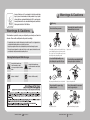
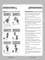


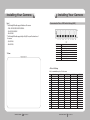
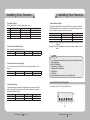

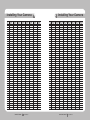
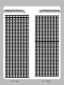
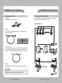
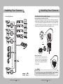

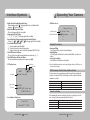
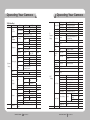

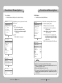

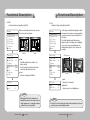
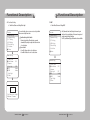
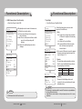


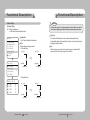
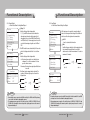

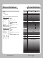
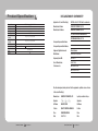

![(deutsch) [PDF ]](http://vs1.manualzilla.com/store/data/006787811_1-a64f3827adfa02011154ebc5e76421a0-150x150.png)