Transcript
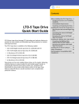
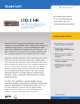
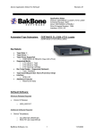
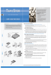
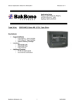
LTO-2 Half-Height Tape Drive
Installing the Desktop Tape Drive
LTO-2 Half-Height Tape Drive
Installing the Internal Tape Drive
Certance LTO Ultrium tape solutions leverage LTO technology and Certance-exclusive features to provide the most reliable and affordable tape data protection to medium and
large businesses.
Certance LTO drives are the most reliable Ultrium drives on the market, delivering reliability features only available from Certance, including multi-speed transfer to
automatically match the host's data transfer rate and Dynamic Powerdown to protect the drive and media in the event of power loss. Combined with SmartVerify to
concurrently verify all data written to the tape, these features make Certance LTO drives a sound investment and a complete data protection solution.
NOTE: This procedure provides step-by-step instructions for installing a desktop LTO-2 Half-Height drive. Please refer to the other side for instructions on installing an internal
version of the drive. Please read the instructions completely before beginning the installation process.
Copyright © 2004 by Certance LLC. All Rights Reserved.
Certance and the Certance logo are trademarks of Certance LLC. Other product names are trademarks or registered trademarks of their respective owners. Certance reserves the right to
change, without notice, product offerings or specifications. No part of this publication may be reproduced in any form without written permission from Certance LLC.
• Part number: 10011345-001 June 2004
Observe the following guidelines:
• Handle the drive by the sides rather than by the top cover to reduce the risk of dropping the drive or damaging it during installation.
• Internal drives contain some exposed components that are sensitive to static electricity. To reduce the possibility of damage from static discharge, the drives are shipped
in a protective antistatic bag. Do not remove the drive from the antistatic bag until you are ready to install it.
• Before you remove the drive from the antistatic bag, touch a metal or grounded surface to discharge any static electricity buildup from your body.
• Always lay the drive either on top of the antistatic bag or place it inside the bag to reduce the chance of damage from static discharge.
• Install LVD drives only in an LVD environment. Do not mix HVD and LVD devices on the same SCSI bus.
• Due to the speed of the LTO-2 Half-Height drive, it is recommended that a maximum of one LTO-2 drive be connected to one host SCSI adapter.
NOTE: This procedure provides step-by-step instructions for installing an internal LTO-2 Half-Height drive. Please refer to the other side for instructions on installing a
desktop version of the drive. Please read the instructions completely before beginning the installation process.
Before installing the drive, read the following instructions:
• Install LVD drives only in an LVD environment. Do not mix
HVD and LVD devices on the same SCSI bus.
• Due to the speed of the LTO-2 drive, it is recommended that
a maximum of one LTO-2 drive be connected to one host
SCSI adapter.
Drive configuration jumper pins
Library Interface
Connector
Pin 1
68-pin SCSI
connector
1. Unpack the contents of your drive package. If any item is
damaged, please contact your place of purchase immediately.
LTO-2 Half-Height Tape Drive
68-pin SCSI
connectors
2. The Desktop tape drive is shipped with a default SCSI ID of 6. If
another SCSI device in the SCSI chain is using this ID, either use
the push-button switch on the back of the drive to change the
drive's SCSI ID or assign a unique SCSI ID to the other SCSI
device. Before changing the SCSI ID on the tape drive, turn off
the tape drive. The change takes effect when the drive is turned
on again. Avoid setting the drive ID to 7.
Power connector
Figure 1. Back of Internal LTO-2 Half-Height Drive
Drive Configuration Jumper Pins
Jumper Settings:
Back of LTO-2 Half-Height Tape Drive
6. With all power to the computer and drive turned off, attach the
SCSI interface cable to the 68-pin SCSI interface connector on
the back of the drive (see Figure 1).
Figure 2. Internal LTO-2 Half-Height Drive Jumper Settings
Figure 1. Two SCSI Termination Examples for the Desktop LTO-2 Half-Height Tape Drive
SCSI Terminators
External
Tape Drive
SCSI device
External
SCSI device
External
Tape Drive
External
SCSI device
(termination enabled)
6. Attach the power cord securely to the power connector on the
back of the Desktop LTO-2 Half-Height drive. Connect the other
end of the power cable to a working AC outlet.
SCSI Terminator
Tape drive
7. Register your tape drive through our Web site at
http://register.certance.com.
(no termination)
(termination
disabled)
SCSI Controller
SCSI Controller
(termination enabled)
Example 1: SCSI termination in a system
that has only external SCSI devices.
Tape drive
(no termination)
SCSI device
SCSI Controller
(termination disabled)
Internal SCSI device
(termination enabled)
Example 2: SCSI termination in a system that
has both internal and external SCSI devices.
3. The drive's default SCSI ID is 6 and terminator power is
disabled.
• To change the SCSI ID, refer to Figure 2.
• To enable terminator power, place a jumper across pins 11
and 12.
5. Secure the drive using two M3.0 X 3 metric screws on each side
of the drive. Do not use screws longer than 3 mm or you may
damage the drive.
4. Attach the SCSI interface cable to either of the two 68-pin SCSI
interface connectors on the back of the drive.
5. If the Desktop LTO-2 Half-Height drive is the last or only device
in a SCSI chain, install a 68-pin LVD terminating plug on the
unused SCSI connector. Figure 1 shows two examples.
2. Shut down the host computer and disconnect the AC power
cord.
4. Select an available 5.25-inch, half-height mounting bay for the
drive. The drive can be mounted either horizontally or vertically.
• For vertical mounting: the side of the drive should be within
5 degrees of horizontal.
• For horizontal mounting: the base of the drive must be within
15 degrees of horizontal and the drive must be right-side up.
3. Turn off all power to the drive and the computer.
Power connector
1. Unpack the contents of your drive package. If any item is
damaged, please contact your place of purchase immediately.
(termination enabled)
Figure 3. Two SCSI Termination Examples for the Internal Drive
SCSI Controller
(termination enabled)
7. By default, the internal LTO-2 Half-Height drive does not provide
SCSI termination. If you use this default setting, place a SCSI bus
terminator or a SCSI device with termination enabled at the end
of the SCSI chain. Figure 3 shows two examples. Note that the
drive provides terminator power if a jumper is placed on the
termination power jumper pins (see step 4 and Figure 2).
8. Attach a 4-pin power cable to the power connector on the back
of the drive (see Figure 1). The recommended 4-pin power
connector is an AMP 1-48024-0 housing with AMP 60617-1
pins or equivalent.
9. Register your drive through our Web site at
http://register.certance.com.