1
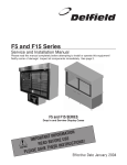
Delfield ™ ® F5 and F15 Series Service and Installation Manual Please read this manual completely before attempting to install or operate this equipment! Notify carrier of damage! Inspect all components immediately. See page 2. F5 and F15 SERIES Drop-In and Serview Display Cases ATION M R O F T IN N A T R O USE IMP E R O F E S! B N O D I A T E C R STRU N I N E O I T S U E A C E TH V A S E S PLEA May 2011 F5 & F15 Series Service and Installation Manual Contents Serial Number Location.....................................................................2 Receiving & Inspecting Equipment....................................................2 Specifications F5 Series....................................................................................3 F15 Series..................................................................................4 Installation F5 Series....................................................................................5 F15 Series..................................................................................6 Shelf Installation................................................................................7 Display Lock Operation......................................................................7 Operation...........................................................................................7 Temperature Control Settings.............................................................8 Pressure Control Settings..................................................................8 Maintenance......................................................................................9 Condenser Air Flow.........................................................................10 Pike Sliding Door.............................................................................11 Replacement Parts Pike Door.................................................................................11 Condensing Unit Assemblies...................................................12 Fluorescent Fixture..................................................................13 Base Door Assembly................................................................13 Base Evaporator Assembly.......................................................14 F15 Control Assembly.............................................................14 Miscellaneous..........................................................................15 Wiring Diagram................................................................................16 Standard Labor Guidelines...............................................................17 Standard Warranties................................................................... 18-19 Serial Number Location The serial number on all self-contained F5 Series units is located near the condensing unit. On all remote F5 Series units the serial number is located on the drop-in frame. The serial number on all self-contained F15 Series units is located behind the compressor housing. On all remote F15 Series units the serial number is located behind the six inch panel in the base. Always have the serial number of your unit available when calling for parts or service. A complete list of authorized Delfield parts depots is available at www.delfield.com. ©2011 The Delfield Company. All rights reserved. Reproduction without written permission is prohibited. SERIAL # MODEL # INSTALLATION DATE: Receiving And Inspecting The Equipment Even though most equipment is shipped crated, care should be taken during unloading so the equipment is not damaged while being moved into the building. 1. Visually inspect the exterior of the package and skid or container. Any damage should be noted and reported to the delivering carrier immediately. 2. If damaged, open and inspect the contents with the carrier. 3. In the event that the exterior is not damaged, yet upon opening, there is concealed damage to the equipment notify the carrier. Notification should be made verbally as well as in written form. 4. Request an inspection by the shipping company of the damaged equipment. This should be done within 10 days from receipt of the equipment. 5. Check the lower portion of the unit to be sure legs or casters are not bent. 6. Also open the compressor compartment housing and visually inspect the refrigeration package. Be sure lines are secure and base is still intact. 7. Freight carriers can supply the necessary damage forms upon request. 8. Retain all crating material until an inspection has been made or waived. Uncrating the Equipment First cut and remove the banding from around the crate. Remove the front of the crate material, use of some tools will be required. If the unit is on legs remove the top of the crate as well and lift the unit off the skid. If the unit is on casters it can be "rolled" off the skid. Delfield ™ 2 For customer service, call (800) 733-8829, (800) 733-8821, Fax (989) 773-3210, www.delfield.com ® F5 & F15 Series Service and Installation Manual F5 Series Specifications 24” (61cm) Deep Remote Drop-In Refrigerated Display Cases MODEL L D VOLTS/ HERTZ/ PHASE H AMPS CABINET LOAD BTU/ HOUR EVAPORATOR DISPLAY CAPACITY BTU °TD TEMP F5MR48N 48" (121.9cm) 24" (61.0cm) 42" (106.7cm) 115/60/1 4.0 1215 150 20° 15° F5SR48N 48" (121.9cm) 24" (61.0cm) 42" (106.7cm) 115/60/1 4.0 1867 150 20° 15° F5PR48N 48" (121.9cm) 24" (61.0cm) 42" (106.7cm) 115/60/1 4.0 1945 150 20° 15° F5MR72N 72" (182.9cm) 24" (61.0cm) 42" (106.7cm) 115/60/1 4.0 1783 450 13° 22° F5SR72N 72" (182.9cm) 24" (61.0cm) 42" (106.7cm) 115/60/1 4.0 2791 450 13° 22° F5PR72N 72" (182.9cm) 24" (61.0cm) 42" (106.7cm) 115/60/1 4.0 2884 450 13° 22° AMPS CABINET LOAD BTU/ HOUR SYSTEM CAPACITY BTU/HOUR H.P. R404A CHARGE, OZ. NEMA PLUG 24” (61cm) Deep Self-Contained Drop-In Refrigerated Display Cases MODEL L D H VOLTS/ HERTZ/ PHASE F5MC48N 48" (121.9cm) 24" (61.0cm) 57.5" (146.1cm) 115/60/1 12.0 1215 2970 1/2 32 5-15P F5SC48N 48" (121.9cm) 24" (61.0cm) 57.5" (146.1cm) 115/60/1 12.0 1867 2970 1/2 32 5-15P F5PC48N 48" (121.9cm) 24" (61.0cm) 57.5" (146.1cm) 115/60/1 12.0 1945 2970 1/2 32 5-15P F5MC72N 72" (182.9cm) 24" (61.0cm) 57.5" (146.1cm) 115/60/1 16.0 1783 5821 3/4 48 5-20P F5SC72N 72" (182.9cm) 24" (61.0cm) 57.5" (146.1cm) 115/60/1 16.0 2791 5821 3/4 48 5-20P F5PC72N 72" (182.9cm) 24" (61.0cm) 57.5" (146.1cm) 115/60/1 16.0 2884 5821 3/4 48 5-20P 30” (76.2cm) Deep Remote Drop-In Refrigerated Display Cases EVAPORATOR DISPLAY CAPACITY MODEL L D H VOLTS/ HERTZ/ PHASE AMPS CABINET LOAD BTU/ HOUR BTU °TD TEMP F5MR48D 48" (121.9cm) 30" (76.2cm) 42" (106.7cm) 115/60/1 4.0 1282 150 20° 15° F5SR48D 48" (121.9cm) 30" (76.2cm) 42" (106.7cm) 115/60/1 4.0 1934 150 20° 15° F5PR48D 48" (121.9cm) 30" (76.2cm) 42" (106.7cm) 115/60/1 4.0 2012 150 20° 15° F5MR72D 72" (182.9cm) 30" (76.2cm) 42" (106.7cm) 115/60/1 4.0 1870 450 13° 22° F5SR72D 72" (182.9cm) 30" (76.2cm) 42" (106.7cm) 115/60/1 4.0 2878 450 13° 22° F5PR72D 72" (182.9cm) 30" (76.2cm) 42" (106.7cm) 115/60/1 4.0 2971 450 13° 22° AMPS CABINET LOAD BTU/ HOUR SYSTEM CAPACITY BTU/HOUR H.P. R404A CHARGE, OZ. NEMA PLUG 30” (76.2cm) Deep Self-Contained Drop-In Refrigerated Display Cases MODEL L D H VOLTS/ HERTZ/ PHASE F5MC48D 48" (121.9cm) 30" (76.2cm) 57.5" (146.1cm) 115/60/1 12.0 1282 2970 1/2 32 5-15P F5SC48D 48" (121.9cm) 30" (76.2cm) 57.5" (146.1cm) 115/60/1 12.0 1934 2970 1/2 32 5-15P F5PC48D 48" (121.9cm) 30" (76.2cm) 57.5" (146.1cm) 115/60/1 12.0 2012 2970 1/2 32 5-15P F5MC72D 72" (182.9cm) 30" (76.2cm) 57.5" (146.1cm) 115/60/1 16.0 1870 5821 3/4 48 5-20P F5SC72D 72" (182.9cm) 30" (76.2cm) 57.5" (146.1cm) 115/60/1 16.0 2878 5821 3/4 48 5-20P F5PC72D 72" (182.9cm) 30" (76.2cm) 57.5" (146.1cm) 115/60/1 16.0 2971 5821 3/4 48 5-20P M = Mirror Back • P = Pass Thru • S = See Thru • R = Remote • C = Self-Contained • N = Narrow • D = Deep 30” Delfield ™ ® For customer service, call (800) 733-8829, (800) 733-8821, Fax (989) 773-3210, www.delfield.com 3 F5 & F15 Series Service and Installation Manual F15 Series Specifications 24” (61cm) Deep Remote Serview Refrigerated Display Cases AMPS CABINET LOAD BTU/ HOUR EVAPORATOR DISPLAY CAPACITY EVAPORATOR BASE CAPACITY BTU °TD TEMP BTU °TD TEMP MODEL L D H VOLTS/ HERTZ/ PHASE F15MR48N 48" (121.9cm) 31.5" (80.0cm) 78" (198.1cm) 115/60/1 4.0 1644 200 23° 12° 120 30° 5° F15SR48N 48" (121.9cm) 33.38" (84.8cm) 78" (198.1cm) 115/60/1 4.0 2296 200 23° 12° 120 30° 5° F15PR48N 48" (121.9cm) 33.38" (84.8cm) 78" (198.1cm) 115/60/1 4.0 2374 200 23° 12° 120 30° 5° F15MR72N 72" (182.9cm) 31.5" (80.0cm) 78" (198.1cm) 115/60/1 4.0 2491 450 13° 22° 120 30° 5° F15SR72N 72" (182.9cm) 33.38" (84.8cm) 78" (198.1cm) 115/60/1 4.0 3499 450 13° 22° 120 30° 5° F15PR72N 72" (182.9cm) 33.38" (84.8cm) 78" (198.1cm) 115/60/1 4.0 3592 450 13° 22° 120 30° 5° AMPS CABINET LOAD BTU/ HOUR SYSTEM CAPACITY BTU/HOUR H.P. R404A CHARGE OZ. NEMA PLUG 24” (61cm) Deep Self-Contained Serview Refrigerated Display Cases MODEL L D H VOLTS/ HERTZ/ PHASE F15MC48N 48" (121.9cm) 31.5" (80.0cm) 78" (198.1cm) 115/60/1 16.0 1569 8146 3/4 48 5-20P F15SC48N 48" (121.9cm) 33.38" (84.8cm) 78" (198.1cm) 115/60/1 16.0 2221 8146 3/4 48 5-20P F15PC48N 48" (121.9cm) 33.38" (84.8cm) 78" (198.1cm) 115/60/1 16.0 2299 8146 3/4 48 5-20P F15MC72N 72" (182.9cm) 31.5" (80.0cm) 78" (198.1cm) 115/60/1 16.0 2361 9422 3/4 48 5-20P F15SC72N 72" (182.9cm) 33.38" (84.8cm) 78" (198.1cm) 115/60/1 16.0 3369 9422 3/4 48 5-20P F15PC72N 72" (182.9cm) 33.38" (84.8cm) 78" (198.1cm) 115/60/1 16.0 3462 9422 3/4 48 5-20P 30” (76.2cm) Deep Remote Serview Refrigerated Display Cases EVAPORATOR DISPLAY CAPACITY EVAPORATOR BASE CAPACITY MODEL L D H VOLTS/ HERTZ/ PHASE AMPS CABINET LOAD BTU/ HOUR BTU °TD TEMP BTU °TD TEMP F15MR48D 48" (121.9cm) 31.5" (80.0cm) 78" (198.1cm) 115/60/1 4.0 1711 200 23° 12° 120 30° 5° F15SR48D 48" (121.9cm) 33.38" (84.8cm) 78" (198.1cm) 115/60/1 4.0 2363 200 23° 12° 120 30° 5° F15PR48D 48" (121.9cm) 33.38" (84.8cm) 78" (198.1cm) 115/60/1 4.0 2441 200 23° 12° 120 30° 5° F15MR72D 72" (182.9cm) 31.5" (80.0cm) 78" (198.1cm) 115/60/1 4.0 2578 450 13° 22° 120 30° 5° F15SR72D 72" (182.9cm) 33.38" (84.8cm) 78" (198.1cm) 115/60/1 4.0 3586 450 13° 22° 120 30° 5° F15PR72D 72" (182.9cm) 33.38" (84.8cm) 78" (198.1cm) 115/60/1 4.0 3679 450 13° 22° 120 30° 5° AMPS CABINET LOAD BTU/ HOUR SYSTEM CAPACITY BTU/HOUR H.P. R404A CHARGE OZ. NEMA PLUG 30” (76.2cm) Deep Self-Contained Serview Refrigerated Display Cases MODEL L D H VOLTS/ HERTZ/ PHASE F15MC48D 48" (121.9cm) 31.5" (80.0cm) 78" (198.1cm) 115/60/1 16.0 1636 8146 3/4 48 5-20P F15SC48D 48" (121.9cm) 33.38" (84.8cm) 78" (198.1cm) 115/60/1 16.0 2288 8146 3/4 48 5-20P F15PC48D 48" (121.9cm) 33.38" (84.8cm) 78" (198.1cm) 115/60/1 16.0 2366 8146 3/4 48 5-20P F15MC72D 72" (182.9cm) 31.5" (80.0cm) 78" (198.1cm) 115/60/1 16.0 2448 9422 3/4 48 5-20P F15SC72D 72" (182.9cm) 33.38" (84.8cm) 78" (198.1cm) 115/60/1 16.0 3456 9422 3/4 48 5-20P F15PC72D 72" (182.9cm) 33.38" (84.8cm) 78" (198.1cm) 115/60/1 16.0 3549 9422 3/4 48 5-20P M = Mirror Back • P = Pass Thru • S = See Thru • R = Remote • C = Self-Contained • N = Narrow 24" • D = Deep 30” Delfield ™ 4 For customer service, call (800) 733-8829, (800) 733-8821, Fax (989) 773-3210, www.delfield.com ® F5 & F15 Series Service and Installation Manual Installation: Self-Contained F5 Series Location Units represented in this manual are for indoor use only. All self-contained units were tested at the factory to assure proper operation. The unit should not be installed directly next to high heat generating equipment (ranges, griddles, etc.). Be sure the location chosen has a counter strong enough to support the total weight of the cabinet and contents. A fully loaded model may weigh as much as 2,000 pounds! Reinforce the counter as necessary to provide for maximum loading. These units are installed by “dropping” them into the counter from above. The counter cutout sizes are as follows: 48” wide units — 18.62" x 23.62" (47.3 cm x 60.0 cm) 72” wide units — 18.62" x 32.62" (47.3 cm x 82.9 cm) Self-contained F5 Series units require airflow to the compressor. Two louvers are provided with each unit and should be installed as illustrated on page 10. Unit is designed to maintain 36°F (2°C) to 40°F (4°C) interior cabinet temperature at 65% or lower ambient relative humidity. Plumbing Self-contained models are standard with a condensate evaporator. If, for some reason, a unit does not have a condensate evaporator, or the evaporator fails, the unit’s drain must have an outlet to an appropriate drainage area or container. Moisture collecting from improper drainage can create a slippery surface on the floor and a hazard to employees. It is the owner’s responsibility to provide a container or outlet CAUTION for drainage. Electrical connection Refer to the amperage data on pages 3 & 4, the serial tag, your local code or the National Electrical Code to be sure the unit is connected to the proper power source. A protected circuit of the correct voltage and amperage must be run for connection of the line cord, or permanent connection to the unit. Self-contained units have an ON/OFF switch in the junction box. Simply turn the switch to ON to begin operation. The power switch should be turned to OFF and the unit disconnected from the power source whenever performing service or maintenance DA NG ER functions. Installation: Remote F5 Series 1.75" (4cm) Cutout 3.00" X 12.00" (8cm X 30cm) Centered Front To Back 0.25" (0.6cm) From End 3.75" (10cm) C R J= Junction Box R= Refrigeration Lines, 0.25" Liquid, 0.37" Suction D= 0.50" I.D. Drain D J 3.75" (10cm) Front Of Unit Typical Mechanical Access (Plan View) All F5 Models Delfield ™ ® For customer service, call (800) 733-8829, (800) 733-8821, Fax (989) 773-3210, www.delfield.com 5 F5 & F15 Series Service and Installation Manual Installation: Self-Contained F15 Series Location Plumbing Units represented in this manual are for indoor use only. Be sure the location chosen has a floor strong enough to support the total weight of the cabinet and contents. A fully loaded model may weigh as much as 3,000 pounds! Reinforce the floor as necessary to provide for maximum loading. For the most efficient refrigeration, be sure to provide good air circulation inside and out. Don’t pack the refrigerator so full that air cannot circulate. Be sure that the exterior of the unit has access to ample air. Avoid hot corners and locations near stoves and ovens. Self-contained models are standard with a condensate evaporator. If your unit does not have a condensate evaporator, or the evaporator fails, the unit’s drain must have an outlet to an appropriate drainage area or container. Moisture collecting from improper drainage can create a slippery surface on the floor and a hazard to employees. It is the owner’s responsibility to CAUTION provide a container or outlet for drainage. Unit is designed to maintain 36°F (2°C) to 40°F (4°C) interior cabinet temperature at 65% or lower ambient relative humidity. Leveling A level cabinet looks better and will perform better because the drain pan will drain properly, the doors will line up with the frames properly and the cabinet will not be subject to undue strain. Units come standard with adjustable legs and bullet feet to make leveling easier. If your unit has casters, install in a stable condition with the front casters locked before operating. Electrical connection Refer to the amperage data on pages 3-4, the serial tag, your local code or the National Electrical Code to be sure the unit is connected to the proper power source. A protected circuit of the correct voltage and amperage must be run for connection of the line cord, or permanent connection to the unit. Self-contained units have an ON/OFF switch located directly behind the louvered panel covering the compressor section. Simply turn the switch to ON to begin operation. The power switch should be turned to OFF and the unit disconnected from the power source whenever performing service or maintenance DA NG ER functions. Installation: Remote F15 Series 30.00" 76cm 1.75" 4cm D 3.75" 10cm 1.00" 2.5cm C R J= Junction Box R= Refrigeration Lines, 0.25" Liquid, 0.37" Suction D= 0.50" I.D. Drain D J 3.75" 10cm Front Of Unit Typical Mechanical Access (Plan View) All F15 Models Delfield ™ 6 For customer service, call (800) 733-8829, (800) 733-8821, Fax (989) 773-3210, www.delfield.com ® F5 & F15 Series Service and Installation Manual Shelf Installation Display Lock Operation Display cases come with four epoxy coated wire shelves that are adjustable in 3-3/4" increments. Maximum weight for shelves is 75 pounds. Overloading shelves can damage equipment or cause bodily injury. At the factory, the keys are taped to the display case. Follow the directions below to lock and unlock the display case. To lock: Line up key ridge with red dot. Insert key and rotate one-half turn. Remove key and push lock bolt in. To open:Line up ridge with red dot. Insert key and rotate key one-half turn. Remove key. Operation After turning the ON/OFF switch to ON the unit’s compressor will begin operating. Delfield display cases are designed to maintain an operational temperature of 36°F to 40°F (2°C to 4°C) in both the display (F5 and F15 Series) and storage areas (F15 Series only). Located on the operator side at the top right is an ON/OFF switch for the display lights. The display temperature control is located in the fan shroud. The F15 base thermostat is located in the mechanical compartment. Use the knob to adjust the temperature, adjustments should be made gradually. Several small adjustments will be more effective than one large adjustment. It may take an hour or longer to realize the temperature change depending on the application and location of the unit. Continuous opening and closing of the doors will hinder the unit’s ability to maintain operational temperatures. If humidity is above 65%, condensation on the glass will be present. Delfield ™ F15 Refrigerated Base Evaporator Fan Operation When the refrigerator is initially powered up or immediately following a power outage the unit will begin cooling after a 3-6 minute delay. During normal operation the evaporator fan pulses independently of the compressor as dictated by the controller as follows: 1. During the cooling mode, compressor and evaporator fan run simultaneously. 2. During the compressor off mode, evaporator fan pulses three minutes on and three minutes off. 3. During an actual defrost event other than the off-cycle defrost, compressor stays off but the evaporator fan runs continuously. Cooling Cycle Compressor On Compressor Off Defrost Cycle Compressor Off Evap Fan Evap Fan Evap Fan Evap Fan Evap Fan Evap Fan On Off On Off On Off X Cycles On 3-Min, Off 3-Min X ® For customer service, call (800) 733-8829, (800) 733-8821, Fax (989) 773-3210, www.delfield.com 7 F5 & F15 Series Service and Installation Manual Display Temperature Control Settings The display temperature control is located on the evaporator assembly on the ceiling of the display case. It is field adjustable and does not require a service agent. The factory setting is 2.5. Set toward 1 for higher temperatures and toward 7 for lower temperatures. Please make small incremental adjustments if a temperature adjustment is necessary. Contact the service department at Delfield +1 (989) 7737981 or your local service agent for additional assistance. Delfield is not responsible for charges incurred while adjusting the thermostat. Base Temperature Control Settings The base temperature control is located in the machine compartment. It is field adjustable and does not require a service agent. The factory setting is 2.5. Set toward 1 for higher temperatures and toward 7 for lower temperatures. Please make small incremental adjustments if a temperature adjustment is necessary. Contact the service department at Delfield +1 (989) 7737981 or your local service agent for additional assistance. Delfield is not responsible for charges incurred while adjusting the thermostat. Pressure Control Settings Low pressure cut in at 20 psi. Low pressure cut out at 5 psi. Differential setting of 15 psi. Delfield ™ 8 For customer service, call (800) 733-8829, (800) 733-8821, Fax (989) 773-3210, www.delfield.com ® F5 & F15 Series Service and Installation Manual Maintenance Door Gasket Maintenance Door gaskets require regular cleaning to prevent mold and mildew build up and also to retain the elasticity of the gasket. Gasket cleaning can be done with the use of warm soapy water. Avoid full strength cleaning products on gaskets as this can cause them to become brittle and crack. Never use sharp tools or knives to scrape or clean the gasket. Gaskets can be easily replaced and do not require the use of tools or an authorized service person. The gaskets are “Dart” style and can be pulled out of the groove in the door and new gaskets can be “pressed” back into place. Drain Maintenance - Base Each unit has a drain located inside the unit that removes the condensation from the evaporator coil and routes it to an external condensate evaporator pan. Each drain can become loose or disconnected during normal use. If you notice water accumulation on the inside of the unit be sure the drain tube is connected to the evaporator drain pan. If water is collecting underneath the unit make sure the end of the drain tube is in the condensate evaporator in the machine compartment. The leveling of the unit is important as the units are designed to drain properly when level. Be sure all drain lines are free of obstructions. Caster Maintenance Wipe casters with a damp cloth monthly to prevent corrosion. The power switch must be turned to OFF and the unit disconnected from the power source whenever performing service, maintenance functions or cleaning the refrigerated area. Refrigerators The interior and exterior can be cleaned using soap and warm water. If this isn’t sufficient, try ammonia and water or a nonabrasive liquid cleaner. When cleaning the exterior, always rub with the “grain” of the stainless steel to avoid marring the finish. Do not use an abrasive cleaner because it will scratch the stainless steel and can damage the breaker strips and gaskets. Stainless Steel Care and Cleaning To prevent discoloration or rust on stainless steel several important steps need to be taken. First, we need to understand the properties of stainless steel. Stainless steel contains 70- 80% iron, which will rust. It also contains 12-30% chromium, which forms an invisible passive film over the steel's surface, which acts as a shield against corrosion. As long as the protective layer is intact, the metal is still stainless. If the film is broken or contaminated, outside elements can begin to breakdown the steel and begin to form discoloration or rust. Proper cleaning of stainless steel requires soft cloths or plastic scouring pads. NEVER USE STEEL PADS, WIRE BRUSHES OR SCRAPERS! Cleaning solutions need to be alkaline based or non-chloride cleaners. Any cleaner containing chlorides will damage the protective film of the stainless steel. Chlorides are also commonly found in hard water, salts, and household and industrial cleaners. If cleaners containing chlorides are used be sure to rinse repeatedly and dry thoroughly. Routine cleaning of stainless steel can be done with soap and water. Extreme stains or grease should be cleaned with a non-abrasive cleaner and plastic scrub pad. Always rub with the grain of the steel. There are stainless steel cleaners available which can restore and preserve the finish of the steels protective layer. Early signs of stainless steel breakdown are small Delfield ™ pits and cracks. If this has begun, clean thoroughly and start to apply stainless steel cleaners in attempt to restore the passivity of the steel. Never use an acid based cleaning solution! Many food products have an acidic content, which can deteriorate the finish. Be sure to clean the stainless steel surfaces of ALL food products. Common items include, tomatoes, peppers and other vegetables. Do not throw items into the display case. Failure to follow these recommendations could result in damage to the interior or blower coil. Overloading, restricting the airflow, and continuous opening and closing of the doors will hamper the units ability to maintain operational temperature. Cleaning the Condenser Coil In order to maintain proper refrigeration performance, the condenser fins must be cleaned of dust, dirt and grease regularly. It is recommended that this be done at least every three months. If conditions are such that the condenser is totally blocked in three months, the frequency of cleaning should be increased. Clean the condenser with a vacuum cleaner or stiff brush. If extremely dirty, a commercially available condenser cleaner may be required. Failure to maintain a clean condenser coil can initially cause high temperatures and excessive run times. Continuous operation with a dirty or clogged condenser coil can result in compressor failure. Neglecting the condenser coil cleaning procedures will void any warranties associated with the compressor and cost to replace the compressor. Never use a high-pressure water wash for this cleaning procedure as water can damage the electrical components located near or at the condenser coil. Doors/Hinges Over time and with heavy use the doors hinges may become loose. If this happens tighten the screws that mount the hinge brackets to the frame of the unit. Loose or sagging doors can cause the hinges to pull out of the frame, which may damage both the doors and the hinges. In some cases this may require qualified service agents or maintenance personnel to perform repairs. Do not place hot pans on/against the blue ABS liner. Do not throw items into the storage area. Failure to follow these recommendations could result in damage to the interior of the cabinet or to the blower coil. Overloading the storage area, restricting the airflow, and continuous opening and closing of the doors and drawers will hamper the units ability to maintain operational temperature. Preventing blower coil corrosion To help prevent corrosion of the blower coil, store all acidic items, such as pickles and tomatoes, in sealable containers. Immediately wipe up all spills. Cleaning the condensate evaporator (remote models only) The stainless steel condensate evaporator pan should be cleaned every six months. Use a vacuum cleaner or damp cloth to remove dust that may have accumulated. This will prevent corrosion of the stainless steel. ® For customer service, call (800) 733-8829, (800) 733-8821, Fax (989) 773-3210, www.delfield.com 9 F5 & F15 Series Service and Installation Manual Condenser Air Flow: F5 F5 units are designed to be operated with two supplied louvered panels for proper air flow. Failure to provide the proper air flow will void the warranty. Louver cut-outs are 22" by 11" (55.9cm by 27.9cm) typical. Cut-outs are to begin a maximum of 4.00" (10.2cm) from the counter-top. Proper installation must provide for air flow to and from the condensing unit. Install as shown below. 48" Wide Units Air Flow Detail Discharge Air Louver Cond. Louver Fresh Air 72" Wide Units Air Flow Detail An “air duct” should be constructed from the air-intake louver to the condenser. This is recommended to prevent recirculation of discharge air. DisCharge Air 11.00" 28cm 22.00" 56cm Cond. Discharge air louver may be located further from fresh air louver or on the opposite side of counter. 22.00" 12.00" 56cm 30cm Louver Minimum Cutout Distance Between Louvers Fresh Air Top View 22.00" 56cm Louver Cutout Delfield ™ 10 For customer service, call (800) 733-8829, (800) 733-8821, Fax (989) 773-3210, www.delfield.com Duct ® F5 & F15 Series Service and Installation Manual Pike Sliding Door All Delfield F5 Series and F15 Series display cases feature a Pike® sliding door assembly. A typical Pike sliding door assembly is shown in the illustration at right. Maintenance Frequent, regular cleaning with a mild soap and water solution will keep the tracks free of foreign matter and will insure many years of service. The glass may be cleaned with one of the many commercial glass cleaners currently available. If it becomes necessary to replace a Pike sliding door assembly or a glass panel, have your unit’s model and serial numbers available when you call Delfield’s Service and Parts Department at (800) 733-8829. Indicate that your unit has the Pike sliding door assembly when you call. Standard With Door Lock Sliding Door Removal Open the door almost completely. Firmly grasp both sides of the door. Lift the door up and move it until it enters a notch and can be lifted higher. Tilt the bottom out without removing the top. Use the top to gently return the spring to the closed position. Remove the door from the top track. Sliding Door Reinstall There is a notch in the top inside corner of the door. Put the spring in the door's notch and move the spring to the open position. Put the top into the track and find the notch where the door can be lifted higher. Set bottom of the door into the track. See-thru Panel Pike Replacement Parts 48" Units 72" Units Part # Description Part # Description 3234636 Bearing, roller, single 3234637 Bearing, roller, double 3234808 Gasket, bumper, 31 13/16" 3234808 Gasket, bumper, 31 13/16" 3234809 Gasket, wiper strip, 30 3/8" 3234809 Gasket, wiper strip, 30 3/8" 3234810 Spring, 17" gold 3233946 Spring, 30" gold 3234803 Track, bottom, 43 7/16" 3234805 Track, bottom, 67 7/16" 3234800 Track top, 44 7/16" 3234802 Track top, 68 7/16" 3455397 See thru panel 3455399 See thru panel 3237549 Replacement lock, units 2007 and after 3237549 Replacement lock, units 2007 and after 3233986 Replacement lock, units prior to 2007 3233986 Replacement lock, units prior to 2007 Note: Pass-thru units have two sets of sliding display doors, see-through and mirror-back units have one set. Delfield ™ ® For customer service, call (800) 733-8829, (800) 733-8821, Fax (989) 773-3210, www.delfield.com 11 F5 & F15 Series Service and Installation Manual Condensing Unit Assembly 1/2 H.P. F5 48" Models 7 6 5 1 2 4 3 Key Delfield Part # Description - 000-BN5-0035 Condensing Unit Assembly 1 026-C58-0031 Shroud, 1/2 HP condenser coil 2 3516554 Blade, fan 9.00”, 5 pedal 3 2160019 Guard, fan, condenser, upright 4 2162716 Motor, fan, 16W, 115V 5 3516462 Capacitor, start, assembly 6 3527026 Compressor, SC12MLX, 115V/60Hz, Danfoss 7 3516331 High pressure switch 8 3516322 Filter dryer, (2) inlet, .25” 9 3516459 Tank, receiver 10 075-231-0031 Pan, condensate 11 3516455 Coil, 1/2 HP condensing 8 9 10 11 Condensing Unit Assembly 3/4 H.P. F15 Models, F5 72" Models 4 1 2 3 5 6 7 Key Delfield Part # Description - 000-BN5-0036 Condensing Unit Assembly 1 026-C58-0032 Shroud, 3/4 HP condenser coil 2 2160019 Guard, fan, condenser, upright 3 3516442 Capacitor, start, run, assembly 4 3527021 Compressor, SC18MLX, 115V/60Hz, Danfoss 5 3516322 Filter dryer, (2) inlet, .25” 6 3516360 Tank, receiver 7 3516456 Coil, condenser, 3/4 HP - 075-231-0031 Pan, condensate - 3516433 Blade, fan 25º, 10”, CW, upright - 2162716 Motor, fan, 16W, 115V Delfield ™ 12 For customer service, call (800) 733-8829, (800) 733-8821, Fax (989) 773-3210, www.delfield.com ® F5 & F15 Series Service and Installation Manual Fluorescent Light Fixture 7 1 Key Part# Description - 000-406-0039 Complete assembly, 60" 000-406-0037 Complete assembly, 36” 000-406-0038 Complete assembly, 48” 1 313-146-0032 cap, end, top mtg, pigtail, -rem. 2 313-146-0033 cap, end, top mtg, blank, -rem. 3 376-A0M-0055 diffuser, fluor. light, 36” 376-A0M-0056 diffuser, fluor. light, 48" 376-A0M-0057 diffuser, fluor. light, 60" 2193907 lamp, fluorescent, 36” 2193908 lamp, fluorescent, 48” 2193909 lamp, fluorescent, 60" 5 2193939 lamp holder, left 6 2193940 lamp holder, right 7 9321266 screw, #8-32 x .50 8 2183613 pigtail, male, 3.5”, rem. ballast 9 9321010 nut, hex, starlock, s/s, #6-32 - 2194992 Ballast, rapid start 36” lamp 8 9 2 5 4 7 4 6 3 Base Door Assembly 5 1 4 Key Part# Description - 000-187-0066 complete door assy., right, 19”, 18.75” x 25.72” 000-187-0067 complete door assy., left, 19”, 18.75” x 25.72” 000-187-0068 complete door assy., right, 24”, 23.75” x 25.72” 000-187-0069 complete door assy., left, 24”, 23.75” x 25.72” 000-187-006A complete door assy., right, 27”, 26.75” x 25.72” 000-187-006B complete door assy., left, 27”, 26.75” x 25.72” 000-187-006C complete door assy., right, 32”, 31.75” x 25.72” 000-187-006D complete door assy., left, 32”, 31.75” x 25.72” 1701183 gasket, door, 19” 1701184 gasket, door, 24” 1701185 gasket, door, 27” 1701186 gasket, door, 32” 3234072 hinge, door, top/LH, bottom/RH 3 1 4 5 3 2 Delfield ™ 4 3234073 hinge, door, top/RH, bottom/LH 5 3234391 hinge, cabinet, L-shaped 6 9321107 bushing, nylon, hinge pin ® For customer service, call (800) 733-8829, (800) 733-8821, Fax (989) 773-3210, www.delfield.com 13 F5 & F15 Series Service and Installation Manual F15 Base Evaporator Assembly Key 1 2 3 4 5 6 7 8 - Part Number 000-248-0030 2160024 2160023 3516095 030-232-0003 3516273 030-233-0001 075-231-0033 030-234-0003 2184317 2195551 Description Coil Assembly, R404A, Ref Guard, fan, 4.7" Fan, axiel, 120V Coil, evaporator Back, evaporator, enclosure Expansion valve, 1/4, R-404a Side, coil, angled Drip pan, evaporator Front, coil Harness, coil Probe sensor, temp/defrost 1 4 2 3 6 5 8 7 F15 Dual Pressure Control Assembly Key 1 2 - Part Number 000-298-003X 2193942 2194810 2190154 Description Dual Pressure Control Assembly Dual pressure control Control, Danfoss, ETC1H-3, 115V Rocker switch, 20A/125V 1 2 Delfield ™ 14 For customer service, call (800) 733-8829, (800) 733-8821, Fax (989) 773-3210, www.delfield.com ® F5 & F15 Series Service and Installation Manual Miscellaneous Replacement Parts Part Number Description Part Number Display Cases Description Mirror Glass 3516172 Blade, fan, Lexan, clear 3455418 Mirror, glass, top, 72” 031-264-0000 Bracket, fan motor, blower coil Shelving & Misc. Parts — Serview Bases 3516173 Fan Guard 3234290 Shelf support, plastic, plug 1” 3516090 Coil, evaporator, 48” 3977984 Shelf, wire, 19” door, 14.38 x 25.25 3516091 Coil, evaporator, 72” 3977998 Shelf, wire, 24” door, 19.38 x 25.25 2193942 Control, pressure, low 3978014 Shelf, wire, 27” door, 22.56 x 25.25 2184063 Harness, elec., power to ballasts 3977983 Shelf, wire, 32” door, 27.38 x 25.25 2162691 Motor, fan, 115V 50/60 9321132 Stud, wall side, for shelf support, 1/4x1.50 039-304-0030 Pan, drip, evap coil, 42” with flat bottom 9321040 Stud, coil side, for shelf support 000-BBO-0030 Pan, drip, evap coil, 42” w/ recessed drain Shelving for Mirror Back Display Cases PMK00011 Pan, drip, evap coil, 72” with flat bottom 3977993 Shelf, wire, 15.75” x 43.25” (M) 000-BBO-0032 Pan, drip, evap coil, 72” w/ recessed drain 3978061 Shelf, wire, 15.75” x 67.25” (M) 2190154 Switch, rocker, 20A/125V, 15A/250V 3978025 Shelf, wire, 21.75” x 43.25” (M) 3516135 Thermometer, hanging, 4” 3978062 Shelf, wire, 21.75” x 67.25” (M) 2194536 Thermostat, in-39.5D/out-22.5D Shelving for See Thru & Pass Thru Display Cases 3516084 Valve, expansion, 1/2 ton, R404A 3978026 Shelf, wire, 17.75” x 43.25” (S&P) 3156101 Solenoid valve 3978063 Shelf, wire, 17.75” x 67.25” (S&P) 3516103 Solenoid coil 120V 3978027 Shelf, wire, 23.75” x 43.25” (S&P) 3978064 Shelf, wire, 23.75” x 67.25” (S&P) F15 Base 2183347 Cord/plug assy, 14/3, NEMA 5-20P 3234645 Leg, 6” with mount plate (4 used on 48” — 6 used on 72”) 356-303-0031 Louver, 18”, 17.94 x 26.34 Delfield ™ (M) = Mirror Back • (S&P) = See Thru & Pass Thru ® For customer service, call (800) 733-8829, (800) 733-8821, Fax (989) 773-3210, www.delfield.com 15 F5 & F15 Series Service and Installation Manual Wiring Diagram: Self-Contained F5 & F15 Series Delfield ™ 16 For customer service, call (800) 733-8829, (800) 733-8821, Fax (989) 773-3210, www.delfield.com ® F5 & F15 Series Service and Installation Manual Standard Labor Guidelines To Repair Or Replace Parts On Delfield Equipment Advice and recommendations given by Delfield Service Technicians do not constitute or guarantee any special coverage. •A maximum of 1-hour is allowed to diagnose a defective component. •A maximum of 1-hour is allowed for retrieval of parts not in stock. •A maximum travel distance of 100 miles round trip and 2-hours will be reimbursed. •Overtime, installation/start-up, normal control adjustments, general maintenance, glass breakage, freight damage, and/or correcting and end-user installation error will not be reimbursed under warranty unless pre-approved with a Service Work Authorization from Delfield. You must submit the number with the service claim. Labor Of 1-Hour Is Allowed To Replace: •Ballast/Light •Circulating Fan Motor and Blade •Compressor Start Components and Overload Protector •Condensate Element •Door Hinges, Locks, and Gaskets •Evaporator/Condenser Fan Motor and Blade •Hi-limit/Thermal Protector Switch •ON/OFF Switch •Solenoid Coil •Springs •Thermostat Labor Of 2 Hours To Replace: •Locate/Repair Leak •Pressure Control •Solenoid Valve Labor Of 3 Hours To Replace: •Condenser or Evaporator Coil •Expansion Valve Labor Of 4 Hours To Replace: •Compressor This includes recovery of refrigerant and leak check. $55.00 maximum reimbursement for refrigerant recovery (includes recovery machine, pump, torch, oil, flux, minor fittings, solder, brazing rod, nitrogen, or similar fees.) Refrigerants: •R404A A maximum of $15.00/lb. or $1.00/oz. will be reimbursed. Delfield ™ ® For customer service, call (800) 733-8829, (800) 733-8821, Fax (989) 773-3210, www.delfield.com 17 F5 & F15 Series Service and Installation Manual Standard One Year Limited Warranty (One year parts, 90 days labor) The Delfield Company (“Delfield”) warrants to the Original Purchaser of the Delfield product (herein called the “Unit”) that such Unit, and all parts thereof, will be free from defects in material and workmanship under normal use and service for a period of one (1) year from the date of shipment of the Unit to the Original Purchaser or, if the Original Purchaser returns the warranty card completely filled out including the date of installation within thirty (30) days of receipt of the Unit, one (1) year from the date of installation. During this one year warranty period, Delfield will repair or replace any defective part or portion there of returned to Delfield by the Original Purchaser which Delfield determines was defective due to faulty material or workmanship. The Original purchaser will pay all labor, crating, freight and related costs incurred in the removal of the Unit of defective component and shipment to Delfield, except that during a period of either ninety (90) days from the date of shipment of the Unit to the Original Purchaser or, if the Original Purchaser returns the warranty card completely filled out including the date of installation within thirty (30) days of receipt of the Unit, ninety (90) days from the date of installation Delfield will pay all related labor costs. Delfield will pay the return costs if the Unit or part thereof was defective. manufacturer or of another make. Unless authorized by Delfield in writing, this warranty does not permit the replacement of any part, including the motor-compressor, to be made with the part of another make or manufacturer. The term “Original Purchaser” as used herein means that person, firm, association, or corporation for whom the Unit was originally installed. Except as provided in any Additional Four Year Protection Plan, if applicable, and the Service Labor Contract, if applicable, the foregoing is exclusive and in lieu of all other warranties, whether written or oral, express or implied. This warranty supersedes and excludes any prior oral or written representations or warranties. Delfield expressly disclaims any implied warranties of merchantability, fitness for a particular purpose, or compliance with any law, treaty, rule or regulation relating to the discharge of substances into the environment. The sole and exclusive remedies of any person relating to the Unit, and the full liability of Delfield for any breach of this warranty, will be as provided in this warranty. This warranty does not apply to any Unit or part thereof that has been subjected to misuse, neglect, alteration, or accident, such as accidental damage to the exterior finish, operated contrary to the recommendations specified by Delfield; or repaired or altered by anyone other than Delfield in any way so as to, in Delfield’s sole judgement, affect its quality or efficiency. This warranty does not apply to any Unit that has been moved from the location where it was originally installed. This warranty also does not cover the refrigerator drier or the light bulbs used in the Unit. The warranty is subject to the user’s normal maintenance and care responsibility as set forth in the Service and Installation Manual, such as cleaning the condenser coil, and is in lieu of all other obligations of Delfield. Delfield neither assumes, nor authorizes any other person to assume for Delfield, any other liability in connection with Delfield’s products. Removal or defacement of the original Serial Number or Model Number from any Unit shall be deemed to release Delfield from all obligations hereunder or any other obligations, express or implied. Parts furnished by suppliers to Delfield are guaranteed by Delfield only to the extent of the original manufacturer’s express warranty to Delfield. Failure of the Original Purchaser to receive such manufacturers warranty shall in no way create any warranty, expressed or implied, or any other obligation or liability on Delfield’s part in respect thereof. IF THE CUSTOMER IS USING A PART THAT RESULTS IN A VOIDED WARRANTY AND A DELFIELD AUTHORIZED REPRESENTATIVE TRAVELS TO THE INSTALLATION ADDRESS TO PERFORM WARRANTY SERVICE, THE SERVICE REPRESENTATIVE WILL ADVISE CUSTOMER THE WARRANTY IS VOID. SUCH SERVICE CALLS WILL BE BILLED TO CUSTOMER AT THE AUTHORIZED SERVICE CENTER’S THEN APPLICABLE TIME AND MATERIALS RATES. CONSIDER: CUSTOMER MAY INITIATE A SERVICE AGREEMENT WITHOUT PARTS COVERAGE. If shipment of a replacement part is requested prior to the arrival in the Delfield factory of the part claimed to be defective, the Original Purchaser must accept delivery of the replacement part on a C.O.D. basis, with credit being issued after the part has been received and inspected at Delfield’s plant and determined by Delfield to be within this warranty. No claims can be made under this warranty for spoilage of any products for any reason, including system failure. The installation contractor shall be responsible for building access, entrance and field conditions to insure sufficient clearance to allow any hood(s), vent(s), or Unit(s) if necessary, to be brought into the building. Delfield will not be responsible for structural changes or damages incurred during installation of the Unit or any exhaust system. Delfield shall not be liable in any manner for any default or delay in performance hereunder caused by or resulting from any contingency beyond Delfield’s control, including, but not limited to, war, governmental restrictions or restraints, strike, lockouts, injunctions, fire, flood, acts of nature, short or reduced supply of raw materials, or discontinuance of the parts by the original part manufacturer. Other than this Delfield Standard One Year Limited Warranty, any applicable Delfield Additional Four Year Protection Plan or applicable Delfield Service Labor Contract, the Original Purchaser agrees and acknowledges that no other warranties are offered or provided in connection with or for the Unit or any other part thereof. In no event will Delfield be liable for special, incidental or consequential damages, or for damages in the nature of penalties. IF DURING THE WARRANTY PERIOD, CUSTOMER USES A PART FOR THIS DELFIELD EQUIPMENT OTHER THAN AN UNMODIFIED NEW OR RECYCLED PART PURCHASED DIRECTLY FROM DELFIELD OR ANY OF ITS AUTHORIZED SERVICE CENTERS AND/OR THE PART BEING USED IS MODIFIED FROM ITS ORIGINAL CONFIGURATION, THIS WARRANTY WILL BE VOID. FURTHER, DELFIELD AND ITS AFFILIATES WILL NOT BE LIABLE FOR ANY CLAIMS DAMAGES OR EXPENSES INCURRED BY THE CUSTOMER WHICH ARISE DIRECTLY OR INDIRECTLY, IN WHOLE OR IN PART, DUE TO THE INSTALLATION OF ANY MODIFIED PART AND/OR PART RECEIVED FROM AN UNAUTHORIZED SERVICE CENTER. If the warranty becomes void, Customer may purchase from Delfield, if available, a Service Agreement or service at the then current time and materials rate. For more information on Delfield warranty’s log on and check out the service section of our web site at www.delfield.com. Under no condition does this warranty give the Original Purchaser the right to replace the defective Unit with a complete Unit of the same Delfield ™ 18 For customer service, call (800) 733-8829, (800) 733-8821, Fax (989) 773-3210, www.delfield.com ® F5 & F15 Series Service and Installation Manual Additional Four Year Protection Plan Delfield Model# Serial # (For Motor-Compressor Only) Installation Date In addition to the Standard One Year Warranty on the Motor-Compressor contained in the above listed Delfield product (the “Unit”), The Delfield Company (“Delfield”) also agrees to repair, or exchange with similar or interchangeable parts in design and capacity at Delfield’s option, the defective Motor-Compressor contained in the Unit (the “Motor-Compressor), or any part thereof, for the Original Purchaser only, at any time during the four (4) years following the initial one (1) year period commencing on the date of installation for the Original Purchaser. Failure of the Original Purchaser to register the registration card containing the Original Purchasers name, address, date of installation, model number and serial number of the Unit containing the MotorCompressor within 30 days from the date of installation shall void this warranty. This additional warranty is only available if the Motor-Compressor is inoperative due to defects in material or factory workmanship, as determined by Delfield in its sole judgement and discretion. The Original Purchaser shall be responsible for returning the defective Motor-Compressor to Delfield prepaid, F.O.B. at the address shown on the back cover of this manual. The term “Original Purchaser” as used herein means that person, firm, association, or corporation for whom the Unit was originally installed. The term “Motor-Compressor” as used herein does not include unit base, air or water cooled condenser, receiver, electrical accessories such as relay, capacitors, refrigerant controls, or condenser fan/motor assembly. This warranty does not cover labor charges incidental to the replacement of parts. This warranty further does not include any equipment to which said condensing unit is connected, such as cooling coils, temperature controls or refrigerant metering devices. This warranty shall be void if the Motor-Compressor, in Delfield’s sole judgement, has been subjected to misuse, neglect, alteration or accident, operated contrary to the recommendations specified by the Unit manufacturer, repaired or altered by anyone other than Delfield in any way so as, in Delfield’s sole judgment, to affect its quality or efficiency or if the serial number has been altered, defaced or removed. This Warranty does not apply to a Motor-Compressor in any Unit that has been moved from the location where it was originally installed. The addition of methyl chloride to the condensing unit or refrigeration system shall void this warranty. General Conditions Delfield shall not be liable in any manner for any default or delay in performance hereunder caused by or resulting from any contingency beyond Delfield’s control, including, but not limited to, war, governmental restrictions or restraints, strike, lockouts, injunctions, fire, flood, acts of nature, short or reduced supply of raw materials, or discontinuance of any part or the Motor-Compressor by the unit manufacturer. This warranty does not give the Original Purchaser of the Motor-Compressor the right to purchase a complete replacement Motor-Compressor of the same make or of another make. It further does not permit the replacement to be made with a Motor-Compressor of another kind unless authorized by Delfield. In the event Delfield authorizes the Original Purchaser to purchase a replacement Motor-Compressor locally, only the wholesale cost of the Motor-Compressor is refundable. Expressly excluded from this warranty are damages resulting from spoilage of goods. Except as provided in any applicable Standard One Year Limited Warranty or applicable Service Labor Contract, the foregoing is exclusive and in lieu of all other warranties, whether written or oral, express or implied. This Warranty supersedes and excludes any prior oral or written representations or warranties. Delfield expressly disclaims any implied warranties of merchantability, fitness for a particular purpose or compliance with any law, treaty, rule or regulation relating to the Motor-Compressor, and the full liability of Delfield for any breach of this warranty, will be as provided in this warranty. Other than any applicable Delfield Standard One year Limited Warranty, this Delfield Additional Four Year Protection Plan and any applicable Delfield Service Labor Contract, the Original Purchaser agrees and acknowledges that no other warranties are offered or provided in connection with or for the MotorCompressor or any part thereof. In no event will Delfield be liable for special, incidental or consequential damages, or for damages in the nature of penalties. Replacement of a defective Motor-Compressor is limited to one (1) MotorCompressor by us during the four (4) year period. Delfield shall replace the Motor-Compressor at no charge. Delfield ™ ® For customer service, call (800) 733-8829, (800) 733-8821, Fax (989) 773-3210, www.delfield.com 19 Delfield ™ ® Covington, TN Mt. Pleasant, MI Thank you for choosing Delfield! Help is a phone call away. Help our team of professional, courteous customer service reps by having your model number and serial number available at the time of your call (800) 733-8829 Model:_______________ S/N: ________________________ Installation Date:_____________ For a list of Delfield’s authorized parts depots, visit our website at www.delfield.com Delfield ™ ® 980 S. Isabella Rd., Mt. Pleasant, MI 48858, U.S.A. • (989) 773-7981 or (800) 733-8829 • Fax (989) 773-3210 • www.delfield.com Delfield reserves the right to make changes in design or specifications without prior notice. ©2011 The Delfield Company. All rights reserved. Printed in the U.S.A. DM5_15 05/11