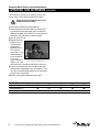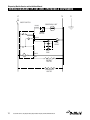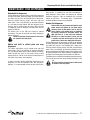
1
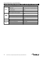
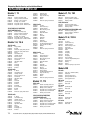
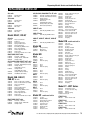
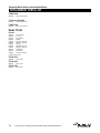
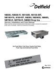
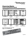
Shelleymatic®
by Delfield
Dispensing Models
Service and Installation Manual
Please read this manual completely before attempting to install or operate this equipment! Notify carrier of damage! Inspect all
components immediately. See page 2.
DIS
Drop-in dish dispensers
TT
Mobile tray/rack
dispensers
CAB
Mobile enclosed dish
dispensers
CD
Disposable cup
dispensers
CT
Mobile cantilever tray/rack
dispensers
TG
Built in tray and rack
dispensers
LT
Drop-in tray dispensers
WCT
Wall mounted cantilever
tray and rack dispensers
Also in this manual: ND, CP, CPB, CM,
CMB, T-H, T2, TGH AND F2-SN
ATION
M
R
O
F
T IN
N
A
T
R
O
SE
U
IMP
E
R
O
EF
ONS!
I
T
C
READ B
U
R
INST
E
S
E
H
T
AVE
S
E
S
A
E
PL
April 2010
Dispensing Models Service and Installation Manual
Contents
RECEIVING & INSPECTING EQUIPMENT.................................. 2
SPECIFICATIONS......................................................................3-5
INSTALLATION . ......................................................................... 6
OPERATION..............................................................................7-8
WIRING DIAGRAMS..............................................................9-10
MAINTENANCE.........................................................................11
TROUBLESHOOTING REFERENCE CHART..............................12
ADJUSTING SELF-LEVELING DISPENSER..............................13
REPLACEMENT PARTS LIST...............................................14-16
Serial Number Location
Dish Dispensers: The serial number is located on the
dispenser housing. Non-heated equipment are not assigned
serial numbers.
Tray & Rack Dispensers: The serial number is located on the
back of the unit or the underside of the flange.
Mobile & Built in Chilled Plate & Mug dispensers: The
serial number is located near the compressor.
Always have the serial number of your unit available when
calling for parts or service.
The units represented in this manual are intended for indoor
use only.
STANDARD LABOR GUIDELINES.............................................17
STANDARD WARRANTY......................................................18-19
©2010 The Delfield Company. All rights reserved. Reproduction without written
permission is prohibited. “Delfield” & “Shelleymatic” are registered trademarks of
The Delfield Company.
Receiving and Inspecting the Equipment
Even though most equipment is shipped crated, care should
be taken during unloading so the equipment is not damaged
while being moved into the building.
1. Visually inspect the exterior of the package and skid or
container. Any damage should be noted and reported
to the delivering carrier immediately.
2. If damaged, open and inspect the contents with the
carrier.
3. In the event that the exterior is not damaged, yet upon
opening, there is concealed damage to the equipment
notify the carrier. Notification should be made verbally
as well as in written form.
4. Request an inspection by the shipping company of the
damaged equipment. This should be done within 10
days from receipt of the equipment.
5. Check the lower portion of the unit to be sure the casters
are not bent.
6. Retain all crating material until an inspection has been
made or waived.
Uncrating the Equipment
First cut and remove the banding from around the crate.
Remove the front of the crate material, use of some tools will
be required. If the unit is on legs remove the top of the crate
as well and lift the unit off the skid. If the unit is on casters
it can be rolled off the skid.
For customer service, call (800) 733-8829, (800) 773-8821, Fax (989) 773-3210, www.delfield.com
Dispensing Models Service and Installation Manual
Specifications
MODEL
NUMBER
LENGTH DEPTH
HEIGHT
MAXIMUM
DISH DIA.
VOLTAGE
(60Hz/1Ø)
AMPS
NEMA
PLUG
Dish Dispensers — Mobile Two Stack
MODEL
NUMBER
LENGTH DEPTH
HEIGHT
MAXIMUM
DISH DIA.
VOLTAGE
(60Hz/1Ø)
AMPS
NEMA
PLUG
Dish Dispensers — Mobile Four Stack
CAB2-500
28.25
17
36
5
N/A
N/A
N/A
CAB4-500
27
27
36
5
N/A
N/A
N/A
CAB2-575
28.25
17
36
5.75
N/A
N/A
N/A
CAB4-575
27
27
36
5.75
N/A
N/A
N/A
CAB2-650
28.25
17
36
6.5
N/A
N/A
N/A
CAB2-725
28.25
17
36
7.25
N/A
N/A
N/A
CAB4-650
27
27
36
6.5
N/A
N/A
N/A
CAB2-813
32.25
17
36
8.12
N/A
N/A
N/A
CAB4-725
27
27
36
7.25
N/A
N/A
N/A
CAB2-913
32.25
17
36
9.12
N/A
N/A
N/A
CAB4-813
32.25
32.25
36
8.12
N/A
N/A
N/A
CAB2-1013
32.25
17
36
10.12
N/A
N/A
N/A
CAB4-913
32.25
32.25
36
9.12
N/A
N/A
N/A
CAB2-1200
37
19
36
12
N/A
N/A
N/A
CAB4-1013
32.25
32.25
36
10.12
N/A
N/A
N/A
CAB2-1450
45
21.5
36
14.5
N/A
N/A
N/A
CAB4-1200
36
36
36
12
N/A
N/A
N/A
CAB2-500-ET 28.25
17
36
5
120
15.0
5-15P
CAB4-1450
42
42
36
14.5
N/A
N/A
N/A
CAB2-575-ET 28.25
17
36
5.75
120
15.0
5-15P
CAB4-500-ET
27
27
36
5
208
17.0
6-20P
CAB2-650-ET 28.25
17
36
6.5
120
15.0
5-15P
CAB2-725-ET 28.25
17
36
7.25
120
15.0
5-15P
CAB4-575-ET
27
27
36
5.75
208
17.0
6-20P
CAB2-813-ET 32.25
17
36
8.12
120
15.0
5-15P
CAB4-650-ET
27
27
36
6.5
208
17.0
6-20P
CAB2-913-ET 32.25
17
36
9.12
120
15.0
5-15P
CAB4-725-ET
27
27
36
7.25
208
17.0
6-20P
CAB2-1013-ET 32.25
17
36
10.12
120
15.0
5-15P
CAB4-813-ET 32.25
32.25
36
8.12
208
17.0
6-20P
CAB2-1200-ET 37
19
36
12
120
15.0
5-15P
CAB4-913-ET 32.25
32.25
36
9.12
208
17.0
6-20P
CAB2-1450-ET 42
21.5
36
14.5
120
15.0
5-15P
CAB4-1013-ET 32.25
32.25
36
10.12
208
17.0
6-20P
CAB2-813-QT 32.25
17
36
8.12
120
15.0
5-20P
CAB4-1200-ET 36
36
36
12
208
17.0
6-20P
CAB2-913-QT 32.25
17
36
9.12
120
15.0
5-20P
CAB4-1450-ET 42
42
42
14.5
208
17.0
6-20P
CAB2-1013-QT 32.25
17
36
10.12
120
15.0
5-20P
CAB4-813-QT 32.25
32.25
36
8.12
208
17.0
6-20P
CAB2-1200-QT 37
19
36
12
120
15.0
5-20P
CAB2-1450-QT 42
21.5
36
14.5
120
15.0
5-20P
CAB4-913-QT 32.25
32.25
36
9.12
208
17.0
6-20P
CAB4-1013-QT 32.25
32.25
36
10.12
208
17.0
6-20P
CAB4-1200-QT 36
36
36
12
208
17.0
6-20P
CAB4-1450-QT 42
42
42
14.5
208
17.0
6-20P
Dish Dispensers — Mobile Three Stack
CAB3-500
41.25
17
36
5
N/A
N/A
N/A
CAB3-575
41.25
17
36
5.75
N/A
N/A
N/A
CAB3-650
41.25
17
36
6.5
N/A
N/A
N/A
CAB3-725
41.25
17
36
7.25
N/A
N/A
N/A
CAB3-813
47.25
17
36
8.12
N/A
N/A
N/A
CAB3-913
47.25
17
36
9.12
N/A
N/A
N/A
CAB3-1013
47.25
17
36
10.12
N/A
N/A
N/A
CAB3-1200
53.25
19
36
12
N/A
N/A
N/A
CAB3-1450
62
21.5
36
14.5
N/A
N/A
N/A
CAB3-500-ET 41.25
17
36
5
208
9.0
6-20P
CAB3-575-ET 41.25
17
36
5.75
208
9.0
6-20P
CAB3-650-ET 41.25
17
36
6.5
208
9.0
6-20P
CAB3-725-ET 41.25
17
36
7.25
208
9.0
6-20P
CAB3-813-ET 47.25
17
36
8.12
208
9.0
6-20P
CAB3-913-ET 47.25
17
36
9.12
208
9.0
6-20P
CAB3-1013-ET 47.25
17
36
10.12
208
9.0
6-20P
CAB3-1200-ET 53.25
19
36
12
208
9.0
6-20P
21.5
36
14.5
208
9.0
6-20P
CAB3-813-QT 47.25
17
36
8.12
208
13.0
6-20P
CAB3-913-QT 47.25
17
36
9.12
208
13.0
6-20P
CAB3-1013-QT 47.25
17
36
10.12
208
13.0
6-20P
CAB3-1200-QT 53.25
19
36
12
208
13.0
6-20P
21.5
36
14.5
208
13.0
6-20P
CAB3-1450-ET 62
CAB3-1450-QT 62
All dimensions shown in specifications are in
inches. For centimeters, multiply by 2.54.
For customer service, call (800) 733-8829, (800) 773-8821, Fax (989) 773-3210, www.delfield.com
Dispensing Models Service and Installation Manual
Specifications
MODEL
NUMBER
FLANGE
DIA.
HEIGHT
CUTOUT MAXIMUM
DIA.
DISH DIA.
VOLTAGE
(60Hz/1Ø)
AMPS
NEMA
PLUG
MODEL
NUMBER
CUTOUT
SIZE
MAXIMUM
RACK/TRAY SIZE
LENGTH
DEPTH
HEIGHT
Tray/Rack Dispensers
Dish Dispensers — Drop-In
DIS-500
8.37
28
7.75
5
N/A
N/A
N/A
LT-2020
22.75 X 26
20 X 20
26.75
27.13
27.5
DIS-575
9.12
28
8.5
5.75
N/A
N/A
N/A
LT2-1221
27 X 27.75
10 X 20
31.75
28.13
27.5
DIS-650
9.87
28
9.25
6.5
N/A
N/A
N/A
LT2-1014
23.75 X 21
12 X 16
23.13
31.75
27.5
DIS-725
10.62
28
10
7.25
N/A
N/A
N/A
LT2-1216
27.75 X 22
14 X 21
31.75
28.13
27.5
DIS-813
11.5
28
10.87
8.12
N/A
N/A
N/A
T-2020
N/A
20 X 20
27.75
28.13
36
DIS-913
12.5
28
11.87
9.12
N/A
N/A
N/A
TT2-2020
N/A
20 X 20
26.25
25.75
37.75
DIS-1013
13.5
28
12.87
10.12
N/A
N/A
N/A
LT-1014
11.75 X 21
10 X 15
15.75
22.13
27.5
DIS-1200
15.37
28
14.75
12
N/A
N/A
N/A
LT-1216
17.75 X 21
12 X 16
21.75
19.13
27.5
LT-1222
19.75 X 21
12 X 21
26.75
19.13
27.5
DIS-1450
17.88
28
17.25
14.5
N/A
N/A
N/A
LT-1418
23.75 X 21
16 X 22
23.75
21.13
27.5
LT-1422
23.75 X 20
14 X 22
27.75
21.13
27.5
Dish Dispensers — Drop-In/Heated
DIS-500-ET
8.37
28
7.75
5
120
8.0
5-15P
LT-1622
27.75 X 21
18 X 26
27.75
23.13
27.5
DIS-575-ET
9.12
28
8.5
5.75
120
8.0
5-15P
LT-1826
23.75 X 21
10 X 14
31.75
25.13
27.5
DIS-650-ET
9.87
28
9.25
6.5
120
8.0
5-15P
CT-1216
N/A
12 X 16
13
N/A
37
5-15P
CT-1221
N/A
12 X 21
15
N/A
37
5-15P
CT-1418
N/A
14 X 18
15
N/A
37
CT-1422
N/A
14 X 22
15
N/A
37
CT-1622
N/A
16 X 22
17.25
N/A
37
CT-1826
N/A
18 X 26
21
N/A
37
CT-2020
N/A
20 X 20
21
N/A
37
T-1014
N/A
10 X15
23.13
16.75
36
T-1216
N/A
12 X 16
22.75
20.13
36
T-1221
N/A
12 X 21
27.25
20.13
36
DIS-725-ET
10.62
DIS-813-ET
11.5
28
28
10
10.87
7.25
8.12
120
120
8.0
8.0
DIS-913-ET
12.5
28
11.87
9.12
120
8.0
5-15P
DIS-1013-ET
13.5
28
12.87
10.12
120
8.0
5-15P
DIS-1200-ET 15.37
28
14.75
12
120
8.0
5-15P
DIS-1450-ET 17.88
28
17.25
14.5
120
8.0
5-15P
Dish Dispensers — Drop-In/Heated/Quick Temp
DIS-813-QT
11.5
28
10.87
8.12
120
8.0
5-15P
DIS-913-QT
12.5
28
11.87
9.12
120
8.0
5-15P
T-1418
N/A
14 X 18
24.75
22.13
36
DIS-1013-QT
13.5
28
12.87
10.12
120
8.0
5-15P
T-1422
N/A
14 X 22
28.75
22.13
36
DIS-1200-QT 15.37
28
14.75
12
120
8.0
5-15P
T-1622
N/A
16 X 22
28.75
24.13
36
DIS-1450-QT 17.88
28
17.25
14.5
120
8.0
5-15P
T-1826
N/A
18 X 26
32.75
26.13
36
T-2020
N/A
20 X 20
27.75
28.13
36
T2-1014
N/A
10 X 15
27.75
22.13
36
T2-1216
N/A
12 X 16
32.75
24.13
36
T2-1221
N/A
12 X 21
32.75
29.13
36
TT-1014
N/A
10 X 14
21.25
15.25
37.75
TT-1216
N/A
12 X 16
18.25
20.75
37.75
TT-1221
N/A
12 X 22
18.25
26.75
37.75
TT-1418
N/A
14 X 18
20.25
22.75
37.75
TT-1422
N/A
14 X 22
21.25
26.75
37.75
TT-1622
N/A
16 X 22
22.25
26.75
37.75
TT-1826
N/A
18 X 26
24.26
30.75
37.75
TT-2020
N/A
20 x 20
26.25
25.75
37.7
TT2-1014
N/A
10 X14
21.25
26.75
37.75
TT2-1216
N/A
12 X 16
36.5
20.75
37.75
TT2-1221
N/A
12 X 22
36.5
25.75
37.75
TT2-1418
N/A
14 X 18
40.5
22.75
37.75
TT2-1422
N/A
14 X 22
40.5
26.75
37.75
TT2-1622
N/A
16 X 22
44.5
26.75
37.75
TT2-1826
N/A
18 X 26
48.5
30.75
37.75
TT2-2020
N/A
20 x 20
52.5
25.75
37.75
All dimensions shown in specifications are in
inches. For centimeters, multiply by 2.54.
For customer service, call (800) 733-8829, (800) 773-8821, Fax (989) 773-3210, www.delfield.com
Dispensing Models Service and Installation Manual
Specifications
MODEL
NUMBER
FLANGE
DIAMETER HEIGHT
CUTOUT
DIAMETER
DISH
DIAMETER
SHIP
WEIGHT
5.12”
2.5”-4.63”
—
28”
5.87” X 5.87"
15
MODEL NUMBER L
D
H
CUTOUT
DIMENSION
MAXIMUM
SHIP
TRAY SIZE AMP WEIGHT
CP-2
32.5”
28”
36”
100
1/3
10.0
410
BUILT-IN TRAY AND RACK DISPENSERS
TG-1014 21.38”
14”
28”
16.88” X 11.5”
TG-1216 18.38”
20”
28”
13.88” X 17.5”
TG-1221 18.38”
25”
28”
13.88” X 22.5”
TG-1418 20.38”
22”
28”
15.88” X 19.5”
TG-1422
26”
20.38” 28”
23.5” X 15.88”
TG-1622 22.38”
26”
28”
17.88” X 23.5”
TG-1826
30”
24.38” 28”
27.5” X 19.88”
TG-2020
25”
26.38” 28”
22.5” X 21.88”
TWO STACK BUILT-IN TRAY AND RACK DISPENSERS
TG2-1014 21.38” 25.63” 28”
16.88” X 23.12”
TG2-1216 22.38” 29.63” 28”
17.88” X 27.12”
TG2-1221 29.63” 29.38” 28”
27.12” X 22.88”
BUILT-IN HEATED TRAY AND RACK DISPENSERS
TG-1221H 25”
20.38” 28”
22.5” X 13.88”
TG-1418H 22”
22.38” 28”
19.5” X 15.88”
TG-1422H 26”
22.38” 28”
23.5” X 15.88”
TG-1826H 30”
26.38” 28”
27.5” X 19.88”
TG-2020H 25”
28.38” 28”
22.5” X 21.88”
CP-4
48”
28”
36”
200
1/3
10.0
485
TGH series include a 9" cord with nema 5-15p plug.
10” X 15”
12” X 16”
12” X 21”
14” X 18”
14” X 22”
16” X 22”
18” X 26”
20” X 21”
—
—
—
—
—
—
—
—
120
128
137
128
121
152
164
159
10” X 15”
12” X 16”
12” X 21”
—
—
—
152
152
159
12” X 21”
14” X 18”
14” X 22”
18” X 26”
20” X 21”
7.0
7.0
7.0
14.0
14.0
121
174
174
184
169
CP series include a 8" cord with nema 5-15p plug.
TWO STACK HEATED BUILT-IN TRAY AND RACK DISPENSERS
TG2-1221H29.63” 29.38” 28”
27.13” X 22.88” 12” X 21”
7.0
169
BUILT-IN CHILLED PLATE DISPENSERS
CPB-2
32”
27.75”
29.63”
100
1/3
10.0
360
TG2-H unit include a 9" cord with nema 5-15p plug
CPB-4
200
1/3
10.0
385
DISPOSABLE CUP DISPENSERS
CD 7.38”
24.5”
BREAD DISPENSERS
SB-1
6.63”
6.63”
MODEL
NUMBER
H
CUTOUT
DIMENSION
24”
24”
24”
24”
24”
24”
7” X 5.62”
8.75” X 5.87”
9.62” X 6.12”
8.62” X 6.75”
10.37” X 6.37”
8.75” X 8.5”
L
D
NAPKIN DISPENSERS
ND-45
7.62” 6”
ND-47
9.37” 6.25”
ND-48 10.25” 6.25”
ND-57
9.25” 7.12”
ND-59
11” 6.75”
ND-67
9.37” 8.17”
MODEL NUMBER L
D
H
NAPKIN
SHIP
DIMENSIONS WEIGHT
4” X 5.37”
4.25” X 7.12”
4.5” X 8”
5.12” X 7”
4.75” X 7.75”
6.87” X 7.12”
12
12
12
12
12
12
CAPACITY
H.P.
AMP
SHIP
WEIGHT
MOBILE CHILLED PLATE DISPENSERS
47.5”
27.75”
29.63”
CPB series include a 8" cord with nema 5-15p plug.
MOBILE CHILLED MUG DISPENSERS
CM-2
48”
28”
36”
60
1/3
10.0
485
CM series include a 8" cord with nema 5-15p plug.
BUILT-IN CHILLED MUG DISPENSERS
CMB-2
47.5”
27.5”
29.63”
60
1/3
10.0
385
CMB series include a 8" cord with nema 5-15p plug.
MODEL NUMBER L
AMP
SHIP
WEIGHT
HEATED MOBILE ENCLOSED TRAY AND RACK DISPENSERS
T-1221H 27.75” 20.12”
36”
12” X 21”
7.0
127
T-1418H
7.0
155
24.75”
D
22.12”
H
36”
CAPACITY
14” X 18”
T-1221H and T-1418H Includes a 5’ cord with nema 5-15p plug.
MODEL NUMBER L
D
H
MAXIMUM
TRAY SIZE
SHIP
WEIGHT
WALL-MOUNTED CANTILEVER TRAY AND RACK DISPENSERS
WCT-1216
13”
22.25”
32”
12” X 16”
81
WCT-1221
13”
27.25”
32”
12” X 21”
95
WCT-1418
15”
24.25”
32”
14” X 18”
98
WCT-1422
15”
28.25”
32”
14” X 22”
101
WCT-1622
17.25”
28.25”
32”
16” X 22”
109
WCT-1826
21”
32.25”
32”
18” X 26”
119
WCT-2020
21”
27.25”
32”
20” X 21”
110
D
H
MODEL NUMBER L
MAXIMUM
TRAY SIZE
SHIP
WEIGHT
TWO STACK, MOBILE OPEN FRAME TRAY AND RACK DISPENSERS
with silverware bin and napkin dispensers
FT2-SN-1216*
43.75”
22.12” 56.38”
12” X 16”
289
FT2-SN-1418*
47.75”
22.12”
56.38”
14” X 18”
298
51.75”
22.12”
56.38”
16” X 22”
306
T-1422H
28.75”
22.12”
36”
14” X 22”
14.0
155
FT2-SN-1622*
T-1826H
32.75”
26.12”
36”
18” X 26”
14.0
195
*Add 1.75” for each dimension to account for bumpers.
T-2020H
27.75”
28.12”
36”
20” X 21”
14.0
185
T-1422H, T-1826H and T-2020H Includes a 5’ cord with nema 5-20p plug.
TWO STACK, HEATED MOBILE ENCLOSED TRAY AND RACK DISPENSERS
T2-1221H 32.75” 29.12”
36”
12” X 21”
14.0
T2-H series include a 5’ cord with nema 5-20p plug.
185
All dimensions shown in specifications are in
inches. For centimeters, multiply by 2.54.
For customer service, call (800) 733-8829, (800) 773-8821, Fax (989) 773-3210, www.delfield.com
Dispensing Models Service and Installation Manual
Installation: DISH DISPENSERS
Location
Drop-in units require a counter cutout of a specific size
for proper fit. Refer to specification data on page three for
the proper dimensions.
Heated units must have minimum 1” (2.5cm) air
gap between the bottom of the dispensing tube and
any surface or objects below. Make sure the tube
will have proper clearance when installing it into a
counter or another piece of equipment.
Stabilizing
CAB models are supplied with casters for your convenience,
for ease of cleaning underneath and mobility.
The unit must be installed in a stable condition
with the front wheels locked. Locking the front
casters after installation is the owner’s and
operator’s responsibility.
Electrical Connection
All heated DIS and CAB models are tested at the factory to
assure proper operation.
Refer to the amperage data on page three, the serial tag, your
local or the National Electrical Code to be sure the unit is
connected to the proper power source. A protected circuit of
the correct voltage and amperage must run for connection of
the line cord.
DIS models plug into a wall receptacle when used as drop-in
models; if they are grouped together in a CAB model, all of the
individual DIS power cords are plugged into the receptacle in
the CAB cabinet. The master power cord on CAB models plugs
into a wall receptacle.
The unit must be disconnected from the
power source whenever performing service or
maintenance functions.
DANGER
Installation: MOBILE AND BUILT-IN CHILLED PLATE AND MUG DISPENSERS
Location
For built-in models (CPB & CMB) be sure the location
chosen has a floor strong enough to support the total
weight of the cabinet and contents. Units in this product
line can weigh as much as 1500 pounds when fully
loaded. Reinforce the floor as necessary to provide for
maximum loading.
Cutout dimensions for CPB-2 and CPB-4 are 13.25” x 23/
25”; two cutouts, 2.125” apart are required on the CPB-4.
Cutout dimensions for the CMB-2 are 25.25” x 22.25”
For the most efficient refrigeration, be sure to provide
good air circulation inside and out. On the CP and CM
mobile units, allow 3.50” clearance for air circulation.
For built in units be sure there is ample air flow from front and
rear of unit with ventilation openings equivalent to one square
foot of opening.
DANGER
DANGER
Refer to the amperage data on page three, the
serial tag, your local or the National Electrical Code
to be sure the unit is connected to the proper power
source. A protected circuit of the correct voltage and
amperage must run for connection of the line cord.
The unit must be disconnected from the
power source whenever performing service or
maintenance functions.
Installation: napkin/cup DISPENSERS
Napkin and cup units require a counter cutout of a specific
size for proper fit. Refer to specification data on page three
for the proper dimensions.
For customer service, call (800) 733-8829, (800) 773-8821, Fax (989) 773-3210, www.delfield.com
Dispensing Models Service and Installation Manual
OPERATION DISH DISPENSERS
Field adjustment
The dispensing height may be adjusted, by following these
instructions in order:
Always wear safety glasses when adjusting
your dispenser. Springs under tension may
recoil when released.
WEAR
If adjusting a heated model, unplug the unit. Allow
the unit to cool completely before handling.
DANGER
1) Lock brakes on mobile units before beginning.
2) Unload the dispenser. Remove dispensers from the unit
by grasping the black plastic guide posts and lifting the
dispenser completely out of the unit.
3) There are minimum of six springs per dispenser. When
adjusting, make sure each section has the same number
and size of springs connected to the tube and make sure the
springs are attached in the same order in each section (see
diagram 1). This will prevent the load of dishes from binding.
TYPICAL EXAMPLE OF SPRING
PLACEMENT. NOTE THAT EACH OF THE
THREE SECTIONS HAS THE SAME
NUMBER AND TYPE OF SPRINGS AND
THAT THE SPRINGS ARE INSTALLED
IN THE SAME ORDER IN EACH
SECTION.
TUBE
FRAME
SPRINGS
H
M
L
CARRIER
BRACKET
= HIGH TENTION SPRING
= MEDIUM TENTION SPRING
= LOW TENSION SPRING
Parts and Service Department). Gently disengage one spring
at a time, unhooking the bottom loop out of the carrier
bracket first, the unhooking the top loop from the tube frame.
(see diagram 2). Remove as many springs as necessary.
6) If level is appropriate, return tube to cart or counter. If
spring adjustment does not position carrier properly, repeat
procedure trying different springs. If this does not work,
a different set of springs may be required. To order call
Spring Requirements
SPRING TENSION
MODEL
DIS-500, 575, 650, 725
DIS-813
DIS-913
DIS-1013
DIS-1200
DIS-1450
MEDIUM
HEAVY
3
3
3
6
6
6
3
3
6
6
6
6
0
3
3
3
6
6
Loading instructions
After adjusting for dispensing height, you are ready to load
your dishes.
Only load a manageable stack of dishes at a time —
approximately 4” (10.2cm) to 5” (12.7cm). Each DIS model
dispensing tube will accommodate a 26” (66cm) stack of plates
or bowls.
(diagram 1)
DANGER
4) If the dispensing
height is too low, add
springs or replace
current springs with
higher tension springs
(springs with higher
tension may be
ordered from Delfield’s
Parts and Service
Department). Gently
engage one spring at
(diagram 2)
a time by hooking
Dish dispenser spring attachments
the top loop of
the spring into the
bracket on the tube frame. Then hook the bottom loop of the
spring into the carrier bracket (see diagram 2). Add as many
springs as necessary.
5) If the dishes are resting too high in the unit, remove springs
or replace current springs with lower tension springs
(springs with lower tension may be ordered from Delfield’s
LIGHT
Keep fingers clear from the edge of
the opening
If the stack is over the guide posts and is bottomed out, it is
full. If stack is over guide posts and not bottomed out (the
stack will bounce up and down), adjust the springs. See “Field
adjustment” instructions on page eight.
Temperature adjustment – ET & QT models only
ET (even-temp) models have a 400 watt heating element
and an adjustable thermostat. The factory setting for
thermostat is “A” which gives an operating temperature
of about 165°F (74°C) and effective plate temperatures of
between 110°F (43°C) to 120°F (49°C) after about two to
three hours of pre-warming.
QT (quick-temp) models have a 700 watt heating element
and an adjustable thermostat. The factory setting for
thermostat is “E” which gives an operating temperature
of about 205°F (96°C) and effective plate temperatures of
between 130°F (54°C) to 150°F (66°C) after about two to
three hours of pre-warming.
(Continued on the next page.)
For customer service, call (800) 733-8829, (800) 773-8821, Fax (989) 773-3210, www.delfield.com
Dispensing Models Service and Installation Manual
Operation: dish dispensers (continued)
The thermostat is located on the bottom of the unit near
the fan motor. Use the following directions to adjust.
Unplug the unit and allow the unit to cool
completely before handling.
DANGER
1) Lock brakes on mobile units before beginning.
2) Unload the dispenser. Remove dispensers from the unit
by grasping the black plastic guide posts and lifting the
dispenser completely out of the unit. It is not necessary to
remove the steel jacket from the dispensing tube.
3) Turn the unit on its side.
4) Remove filter from
bottom of unit. It
is not necessary
to remove the
perforated screen.
The screen has
access holes in it to
allow adjustment
of the thermostat.
The screen is
(diagram 3)
shown removed in
Location of thermostat adjustment screw
diagram 3 to show
the location of the thermostat adjustment screw only.
5) Use a small screw-driver to reach the adjustment screw
located under the perforated screen (see diagram 3). Turn
the screw to the desired setting based on the “thermostat
settings chart” shown below.
6) Reattach the filter before operating the unit again.
Heated Unit Thermostat Settings
Temperature Setting
"A"
"B"
"C"
"D"
"E"
Operating Temperature (°F)
165
175
185
195
205
Operating Temperature (°C)
74
79
85
91
96
For customer service, call (800) 733-8829, (800) 773-8821, Fax (989) 773-3210, www.delfield.com
Dispensing Models Service and Installation Manual
Wiring diagrams: heated dish dispensers
DIS, T-H, & TG-H
MODELS
CORD &
PLUG
MOTOR
ON/OFF
SWITCH
HEATER
THERMOSTAT
LIMIT
CAB
MODELS
DIS
DIS
DIS
DIS
CAB MODELS CONTAIN
SEVERAL DIS UNITS WIRED TOGETHER
For customer service, call (800) 733-8829, (800) 773-8821, Fax (989) 773-3210, www.delfield.com
Dispensing Models Service and Installation Manual
Wiring diagrams: CP, CM, CMB, CPB MODELS dispensers
L1
N
ON/OFF SWITCH
CONDENSING UNIT
BLACK/
ORANGE
2
C1
PRESS
SWITCH
4
C1
X
PURPLE
ORANGE
FAN
DELAY
3
C1
1
C1
TIMER
N
WHITE
EVAP
FANS
RED
DEFROST
HEATER
CONDENSATE
HEATER
10
For customer service, call (800) 733-8829, (800) 773-8821, Fax (989) 773-3210, www.delfield.com
G
Dispensing Models Service and Installation Manual
Maintenance: dish dispensers
Unheated dish dispensers
Lift the dispenser out of the counter or CAB cart by grasping
the black dish guides and lifting straight up and out. Remove
any debris that may be in the assembly with a damp cloth.
Clean the stainless steel by using a soft cloth, soap and
warm water. If this is not sufficient, try ammonia and water
or a non-abrasive liquid cleaner. Rub with the grain of the
stainless steel to avoid marring the finish. When cleaning
is completed, insert the dispenser assembly back into the
counter or CAB cart.
The bottom rails on the CAB cart should be cleaned
occasionally. They may be accessed most easily through the
bottom of the unit.
Do not use abrasive cleaner because it will scratch
the stainless steel and plastic.
Mobile and built in chilled plate and mug
dispensers
The interior and exterior can be cleaned using soap and
swarm water. If this is not sufficient, try ammonia and water
or a non-abrasive liquid cleaner. When cleaning the exterior,
always rub with the “grain” of the stainless steel to avoid
marring the finish. Do not use an abrasive cleaner because it
will scratch the stainless steel and plastic.
In order to maintain proper refrigeration performance, the
condenser fins must be cleaned of dust, dirt and grease
regularly. It is recommended that this be done at least every
three months. If conditions are such that the condenser is
totally blocked in three months, the frequency of cleaning
should be increased. Clean the condenser with a vacuum
cleaner or stiff brush. If extremely dirty, a commercially
available condenser cleaner may be required.
Heated dish dispensers
Heated units must be disconnected from the main
power source and allowed to cool down before
cleaning. Cords on DIS models used as drop-ins
into a counter or into another piece of equipment
DANGER
are directly connected to the power source. On
CAB units there is a cord from each individual
DIS tube to a central receptacle on the cart and
DANGER
a separate cord from that receptacle to the main
power source. Never hose down units with water.
Lift the dispenser out of the counter or CAB cart by grasping
the black dish guides and lifting straight up and out. Remove
any debris that may be in the assembly with a damp cloth.
Clean the stainless steel by using a soft cloth, soap and warm
water. If this is not sufficient, try ammonia and water or a nonabrasive liquid cleaner. Rub with the grain of the stainless steel
to avoid marring the finish. When cleaning is completed, insert
the dispenser assembly back into the counter or CAB cart.
The bottom rails on the CAB cart should be cleaned occasionally.
They may be accessed most easily through the bottom of the
unit.
Do not use abrasive cleaner because it will scratch
the stainless steel and plastic.
For customer service, call (800) 733-8829, (800) 773-8821, Fax (989) 773-3210, www.delfield.com
11
Dispensing Models Service and Installation Manual
Troubleshooting reference chart: heated dish dispensers
Problem
No Heat
Possible Cause
Power cord disconnected
1a) GFCI tripped
Disconnected ON/OFF switch or ON/OFF switch
in the OFF position
Defective heating element
Air circulating fan defective or blocked
Unit plugged into incorrect voltage
Not Hot
Enough
Too Hot
Noisy
12
Thermostat set too low
Air circulating fan partially blocked
Not waiting long enough for pre-heating
Solutions
Check power source to unit and receptacle at the
underside of the cabinet. Reset GFCI receptical position
Replace ON/OFF switch; turn ON/OFF switch to on
position
Replace element
Replace motor, or remove blockage from fan
Check volatge supply and compare to unit's voltage
rating
Adjust thermostat to a higher setting
Remove blockage
Thermostat set too high
90 minutes is a good average pre-heat on DIS
models
Adjust thermostat to a lower setting
Thermostat defective
Replace Thermostat
Defective air circulating motor
Obstruction at air circulating motor
Loose fan blade
Replace motor
Free obstruction
Tighten blade
For customer service, call (800) 733-8829, (800) 773-8821, Fax (989) 773-3210, www.delfield.com
Dispensing Models Service and Installation Manual
Adjusting self-leveling dispensers
Adjusting the self-leveling dispenser
Tools Needed: One small flat head screw driver;
One Phillips head screw driver
1. Always wear safety glasses when adjusting your dispenser.
Also, lock brakes on mobile units before beginning.
2. Unload dispenser and remove stainless steel load tray by
lifting straight up and set it aside (see fig. 1). For Models
LT skip to step #6.
5. Use Phillips head
screw driver to remove
front panel on the
elevator housing (see
fig. 3).
6. If carrier is riding
too high, you need
to remove springs.
With carrier all the
way to the top, gently
disengage one spring
at a time, unhooking
bottom loop out of
carrier bracket (see fig.
4). Remove as many
springs as necessary.
If carrier is riding too
low, you need to add
springs. With carrier
all the way to the top,
gently engage one
spring at a time by
hooking bottom loop
of spring into carrier
bracket. Add as many
springs as necessary.
(figure 1) Sample unit
3. Use small regular screw driver to loosen each retainer
mounted on stainless steel rod at top of each elevator
housing.
4. To remove
elevator housing,
lift housing
straight up to
clear the stud on
unit base. Then
gently swing the
bottom of the
housing towards
the inside of the
unit and pull
housing out of
the unit (see fig.
2). Lay housing
on flat surface.
(figure 3) Remove front panel
(figure 4) Remove or add springs
7. When finished, put
elevator housing back in unit (except on models LT) and
put stainless steel load tray back on elevator housings.
Load unit to test dispensing level. If spring adjustment
does not position carrier properly, repeat procedure #6
trying different springs. If this does not work, a different
set of springs may be required. To order, call The Delfield
Parts and Service Department.
8. If level is appropriate, put front panels back on and
tighten retainer.
CAUTION
Dispenser should not be operated with front
panels off elevator housing.
OTE: When adjusting the elevators make sure each have the
N
same number and size of springs connected to the carrier on
both sides. This will prevent the load tray from binding.
(figure 2) Remove elevator housing
For customer service, call (800) 733-8829, (800) 773-8821, Fax (989) 773-3210, www.delfield.com
13
Dispensing Models Service and Installation Manual
REPLACEMENT PARTS LIST
Models T, T2
1014 units
0201735
6150201
6230170
6320257
M3234180
M3234185
Elevator assembly, small
Spring, extension, 0.58lbs/in
Bumper, corner, small pvc
Bearing, elev, o.375ID
Polyolefin caster 4” with brake
Polyolefin caster 4” without brake
1216/1222/1418/ 1422/1520/
1622/1826/2020 units
0201709
6150202
6230170
6320257
M3234180
M3234185
Elevator assembly, large
Spring, extension, 0.28lbs/in
Bumper, corner, small pvc
Bearing, elev, o.375ID
Polyolefin caster 4” with brake
Polyolefin Caster 4” without brake
Models T-H, TG-H
1221-H units
0201740
6230007
6150201
6150202
0048542
0201046
6190269
0047140
0047153
6190181
6190180
6160024
6160007
6190085
6230314
Large elevator
Bearing
Extension spring, heavy tension
Extension spring, med tension
Carrier
Heat module assy
Heating element
Motor housing
Motor housing screen
Thermostat
High limit switch
Motor
Fan blade
Cord/plug
Air filter
1418-H units
3234180
0201046
6190269
0047153
6190181
6190180
6160024
6160007
6190085
6230314
2183347
6230170
6230007
0047621
6150202
4” Caster
Heat module assy
Heating element
Motor housing screen
Thermostat
High limit switch
Motor
Fan blade
Cord/plug
Air filter
Cord/plug
Corner bumper
Bearing
Carrier
Extension spring, med tension
1422-H units
3234180
0201046
6190269
0047153
6190181
6190180
6160024
6160007
6190085
6230314
14
4” Caster
Heat module assy
Heating element
Motor housing screen
Thermostat
High limit switch
Motor
Fan blade
Cord/plug 18-3
Air filter
2183347
6230170
0201709
6230007
0048583
6150202
Cord/plug 14-3
Corner bumper
Large elevator assy
Bearing
Carrier
Extension spring, med tension
1826-H units
3234180
0201046
6190269
0047153
6190181
6190180
6160024
6160007
6190085
6230314
2183347
6230170
0681855
0201709
6230007
0048584
6150202
4” caster
Heat module assy
Heating element
Motor housing screen
Thermostat
High limit switch
Motor
Fan blade
Cord/plug
Air filter
Cord/plug
Corner bumper
LT-1826 tray/rack dispenser
Large elevator assembly
Bearing
Carrier
Extension spring, med tension
2020-H units
3234180
0201046
6190269
0047153
6190181
6190180
6160024
6160007
6190085
6230314
2183347
6230170
0681811
0201709
6230007
0048503
6150202
4” caster
Heat module assy
Heating element
Motor housing screen
Thermostat
High limit switch
Motor
Fan blade
Cord/plug 18-3
Air filter
Cord/plug 14-3
Corner bumper
LT-2020 tray/rack dispenser
Large elevator assy
Bearing
Carrier
Extension spring, med tension
Models TT, TT2
1014 units
0201731
6150201
6230170
6230188
6230218
6320257
Elevator assembly, small 27.5
Spring, extension, 0.58lbs/in
Bumper, corner, small pvc
Polyolefin caster 4” without brake
Polyolefin caster 4” with brake
Bearing, elev, 0.375ID
1216/1222/1418/1422/1520/
1622/1826/2020 units
0201734
6150202
6230170
6230188
6230218
6320257
Elevator assembly, large
Spring, extension, 0.28lbs/in
Bumper, corner, small pvc
Polyolefin caster 4” without brake
Polyolefin caster 4” with brake
Bearing, elev, 0.375ID
For customer service, call (800) 733-8829, (800) 773-8821, Fax (989) 773-3210, www.delfield.com
Models LT, TG, TG2
1014 units
0201735
6150201
6320257
Elevator assembly, small
Spring, extension, 0.58lbs/in
Bearing .375ID
1216/1222 units
0201709
6150201
6320257
Elevator assembly, large
Spring, extension, 0.58lbs/in
Bearing .375ID
1418/1422/1520/1622/1826/2020 units
0201709
6150202
6320257
Elevator assembly, large
Spring, extension, 0.28lbs/in
Bearing .375ID
Models T2-H, TG2-H
1221 units
3234180
0201046
6190269
0047153
6190181
6190180
6160024
6160007
6190085
6230314
2183347
6230170
0681852
0201735
6230007
0048708
6150201
4” caster
Heat module assy
Heating element
Motor housing screen
Thermostat
High limit switch
Motor
Fan blade
Cord/plug
Air filter
Cord/plug
Corner bumper
LT2-1221 Tray/Rack Dispenser
Elevator assy
Bearing
Carrier
Extension spring, heavy tension
Models DIS
All units
6230314
6230244
6150201
6150202
6150203
500 units
6200121
6970011
575 units
6200122
6970012
650 units
6200123
6970013
725 units
6200124
6970014
813 units
6200125
6970015
Filter, air, 6” diameter (DDS)
Guide post
Spring, heavy tension
Spring, medium tension
Spring, light tension
Spinning head
Wire head
Spinning head
Wire head
Spinning head
Wire head
Spinning head
Wire head
Spinning head
Wire head
Dispensing Models Service and Installation Manual
REPLACEMENT PARTS LIST
913 units
6200126
6970016
1013 units
6200127
6970017
1200 units
6200128
6970018
1450 units
6200129
6970026
Spinning head
Wire head
Spinning head
Wire head
Spinning head
Wire head
6230314
6230244
6150201
6150202
6150203
6190085
6160024
6190180
2190154
6190181
Filter, air, 6” diameter
Guide post
Spring, heavy tension
Spring, medium tension
Spring, light tension
Cord with plug, NEMA 5-15P 5’
Motor, 115V 50-60Hz
Switch, high-limit, 245°F
Switch rocker
Thermostat, automatic 165°F - 205°F
500/575/650/725 ET units
6160008
6190250
0201044
Fan blade, 3” diameter
Heating element, 120V/327W
Heating module
813/913/1013/1200/1450 ET & QT units
6160007
6160008
6190254
6190269
0201045
0201046
Fan blade, 4” diameter (QT models)
Fan blade, 120V/327W (ET models)
Heating element,
120V/327W (ET models)
Heating Element
120V/700W (QT models)
Heating module (ET models)
HTG Module (QT models)
Model CAB, CAB-ET,
CAB-QT All units
3234180
3234185
6230314
6230244
6150202
6150203
6190085
6160024
6190180
2190154
6190181
Caster, 4” with brake (2 needed)
Caster, 4” without brake (2 needed)
Filter, air, 6” diameter
Guide post
Spring, medium tension
Spring, light tension
Cord with plug, NEMA 5-15P 3’
Motor, 115V 50-60Hz
Switch, high-limit, 245°F
Switch rocker
Thermostat, automatic 165°F - 205°F
500/575/650/725 ET units
6160008
6190250
0201044
6160007
6160008
6190254
6190269
0201045
0201046
Fan blade, 4” diameter (QT models)
Fan blade, 120V/327W (ET models)
Heating element,
120V/327W (ET models)
HTG element,
120V/700W (QT models)
Heating module (ET models)
HTG module (QT models)
CAB2-ET units
Spinning head
Wire head
Model DIS-ET, DIS-QT
All units
813/913/1013/1200/1450 ET & QT units
Fan blade, 3” diameter
Heating element, 120V/327W
Heating module
2183348
Cord with plug, NEMA 5-15P 6’
CAB2-QT units
2183347
Cord with plug, NEMA 5-20P 6’
CAB3-ET, CAB4-ET, CAB3-QT, CAB4-QT
units
6190079
Cord with plug, NEMA 6-20P 6’
Model SB
0201196
6150024
0201198
Spring head assy
Dish spring
Hinged lid assy
Model ND
ND-45
0047225
0047226
6150203
ND-47
0047127
0047152
6150203
ND-48
0047227
0047229
6150203
ND-57
0047239
0047241
6150203
ND-59
0047237
0047247
6150203
ND-47
0047250
0047251
6150203
Cover
Head
Extension spring
Cover
Head
Extension spring
Cover
Head
Extension spring
Cover
Head
Extension spring
Cover
Head
Extension spring
Cover
Head
Extension spring
Model CP - mobile and built in
3234180
6230019
9321122
9321198
3516070
3516225
3526710
3516101
2193927
4” caster
Aluminum hinge
Snap bushing 1.50 black
Bushing 1.00 snap
Low temp cooler
Expansion valve
Condensing unit
Filter dryer
Pressure control
0100049
2194199
2194151
6700027
6230186
6200068
6230233
6150077
0201603
6230109
6230110
3234110
2214110003
0047033
0048864
2190154
6230172
2183348
Electric condensate evap. pan
Heating element
Paragon timer
Throat collar
Snap in w/screen vent
Spinning head
Spring head adjustment
Spring compression
Lid assy
Extruded hinge
Plastic insert hinge
Lift cover chrome handle
Louver 13.00 x 25.00
Side louver 13.00 x 13.50
Side louver 9.00 x 13.50
Rocker switch
Corner bumper
Cord/plug
Model CM - mobile and built in
3516070
3516225
3234180
9321122
9321198
3526710
3516101
2193927
0100049
2194199
2194151
0044074
0201737
6320007
6150201
6150202
6230024
0047745
0201525
6230109
6230110
3234110
2214110003
0047033
0048864
2190154
6230172
2183348
Unit cooler
Expansion valve
4” caster
Bushing 1.50 black
Bushing 1.00 snap
Condensing unit
Filter dryer
Pressure control
Electric condensate evap. pan
Heating element
Paragon timer
Throat collar
Large elevator assy
Bearing .50
Extension spring .58
Extension spring .28
Retainer
Carrier
Lid assy
Extruded hinge
Plastic insert hinge
Lift cover chrome handle
Louver 13.00 x 25.00
Side louver 13.00 x 13.50
Side louver 9.00 x 13.50
Rocker switch
Corner bumper
Cord/plug
Model CT - WCT Series
6230170
3234180
6230068
6150206
Small bumper corner
4” caster (CT series only)
Bearing
Extension spring
In addition to the above parts
CT/WCT-1216
0047481
Carrier 12.50 x 16.50
CT/WCT-1221
0047486
Carrier 12.50 x 21.50
CT/WCT-1418
0047490
Carrier 14.56 x 18.56
CT/WCT-1422
0047491
Carrier 14.50 x 22.50
For customer service, call (800) 733-8829, (800) 773-8821, Fax (989) 773-3210, www.delfield.com
15
Dispensing Models Service and Installation Manual
REPLACEMENT PARTS LIST
CT/WCT-1622
0047496
Carrier 16.56 x 22.56
CT-1821 and WCT-2020
0047499
Carrier 20.56 x 21.56
CT/WCT-1826
0047498
Carrier 18.56 x 26.56
Model FT2-SN
All units
6230170
6230218
0201734
6320007
6150201
6150202
6230024
0680934
6150203
0047241
0047239
3234052
Corner bumper
4” caster
Large elevator
Bearing
Extension spring .58
Extension spring .28
Retainer
ND-napkin dispenser
Extension spring .16
Head ND-57
Cover ND-57
Silverware container
In addition to the above parts
FT2-SN-1216
0048492
Carrier 1216
FT2-SN-1418
0047621
Carrier 1418
FT2-SN-1622
0047568
16
Carrier 1622
For customer service, call (800) 733-8829, (800) 773-8821, Fax (989) 773-3210, www.delfield.com
Dispensing Models Service and Installation Manual
Standard Labor Guidelines To Repair or Replace Parts on Delfield Equipment
Advice and recommendations given by Delfield Service Technicians do not constitute or guarantee any special coverage.
•A maximum of 1-hour is allowed to diagnose a defective component.
•A maximum of 1-hour is allowed for retrieval of parts not in stock.
•A maximum travel distance of 100 miles round trip and 2-hours will be reimbursed.
•Overtime, installation/start-up, normal control adjustments, general maintenance, glass breakage, freight damage, and/or
correcting and end-user installation error will not be reimbursed under warranty unless pre-approved with a Service Work
Authorization from Delfield. You must submit the number with the service claim.
LABOR OF 1-HOUR IS ALLOWED TO REPLACE:
•Thermostat
•Infinite Switch
•Door Jamb Switch
•Solenoid Coil
•Hi-limit/Thermal Protector Switch
•Fan Delay/Defrost Termination Switch
•Compressor Start Components and Overload Protector
•Defrost Timer
•Thermometer
•Gear Box
•
•
•
•
•
•
•
•
•
Contactor/Relay
Transformer
Evaporator/Condenser Fan Motor and Blade
Circulating Fan Motor and Blade
Microprocessor Control
Water Level Sensor/Probe
Door Hinges, Locks, and Gaskets
Condensate Element
Springs/Lowerator
LABOR OF 2 HOURS TO REPLACE:
•Drawer Tracks/Cartridges
• Defrost Element
•Pressure Control
• Heating Element
•Solenoid Valve
• Locate/Repair Leak
LABOR OF 3 HOURS TO REPLACE:
•EPR or CPR Valve
• Condenser or Evaporator Coil
•Expansion Valve
LABOR OF 4 HOURS TO REPLACE
•Compressor
This includes recovery of refrigerant and leak check.
$55.00 maximum reimbursement for refrigerant recovery (includes recovery machine, pump, torch, oil, flux, minor fittings,
solder, brazing rod, nitrogen, or similar fees.)
REFRIGERANTS
•R22 A maximum of $4.00/lb. or 25¢/oz. will be reimbursed.
•R134A A maximum of $5.00/lb. or 31¢/oz. will be reimbursed.
•R404A A maximum of $15.00/lb. or $1.00/oz. will be reimbursed.
For customer service, call (800) 733-8829, (800) 773-8821, Fax (989) 773-3210, www.delfield.com
17
Dispensing Models Service and Installation Manual
Standard One Year Warranty (One year parts, 90 days labor.)
The Delfield Company (“Delfield”) warrants to the Original Purchaser
of the Delfield product (herein called the “Unit”) that such Unit, and all
parts thereof, will be free from defects in material and workmanship
under normal use and service for a period of one (1) year from
the date of shipment of the Unit to the Original Purchaser or, if the
Original Purchaser returns the warranty card completely filled out
including the date of installation within thirty (30) days of receipt
of the Unit, one (1) year from the date of installation. During this
one year warranty period, Delfield will repair or replace any defective
part or portion there of returned to Delfield by the Original Purchaser
which Delfield determines was defective due to faulty material or
workmanship. The Original purchaser will pay all labor, crating, freight
and related costs incurred in the removal of the Unit of defective
component and shipment to Delfield, except that during a period of
either ninety (90) days from the date of shipment of the Unit to the
Original Purchaser or, if the Original Purchaser returns the warranty
card completely filled out including the date of installation within thirty
(30) days of receipt of the Unit, ninety (90) days from the date of
installation Delfield will pay all related labor costs. Delfield will pay the
return costs if the Unit or part thereof was defective.
The term “Original Purchaser” as used herein means that person, firm,
association, or corporation for whom the Unit was originally installed.
This warranty does not apply to any Unit or part thereof that has
been subjected to misuse, neglect, alteration, or accident, such as
accidental damage to the exterior finish, operated contrary to the
recommendations specified by Delfield; or repaired or altered by anyone
other than Delfield in any way so as to, in Delfield’s sole judgement,
affect its quality or efficiency. This warranty does not apply to any Unit
that has been moved from the location where it was originally installed.
This warranty also does not cover the refrigerator drier or the light
bulbs used in the Unit. The warranty is subject to the user’s normal
maintenance and care responsibility as set forth in the Service and
Installation Manual, such as cleaning the condenser coil, and is in
lieu of all other obligations of Delfield. Delfield neither assumes, nor
authorizes any other person to assume for Delfield, any other liability
in connection with Delfield’s products.
Removal or defacement of the original Serial Number or Model Number
from any Unit shall be deemed to release Delfield from all obligations
hereunder or any other obligations, express or implied.
Parts furnished by suppliers to Delfield are guaranteed by Delfield only
to the extent of the original manufacturer’s express warranty to Delfield.
Failure of the Original Purchaser to receive such manufacturer’s express
warranty to Delfield. Failure of the Original Purchaser to receive such
manufacturers warranty shall in no way create any warranty, expressed
or implied, or any other obligation or liability on Delfield’s part in respect
thereof.
IF THE CUSTOMER IS USING A PART THAT RESULTS IN A VOIDED
WARRANTY AND A DELFIELD AUTHORIZED REPRESENTATIVE
TRAVELS TO THE INSTALLATION ADDRESS TO PERFORM WARRANTY
SERVICE, THE SERVICE REPRESENTATIVE WILL ADVISE CUSTOMER
THE WARRANTY IS VOID. SUCH SERVICE CALLS WILL BE BILLED
TO CUSTOMER AT THE AUTHORIZED SERVICE CENTER’S THEN
APPLICABLE TIME AND MATERIALS RATES. CONSIDER: CUSTOMER
MAY INITIATE A SERVICE AGREEMENT WITHOUT PARTS COVERAGE.
If shipment of a replacement part is requested prior to the arrival in
the Delfield factory of the part claimed to be defective, the Original
Purchaser must accept delivery of the replacement part of a C.O.D.
18
basis, with credit being issued after the part has been received and
inspected at Delfield’s plant and determined by Delfield to be within this
warranty.
Under no condition does this warranty give the Original Purchaser the
right to replace the defective Unit with a complete Unit of the same
manufacturer or of another make. Unless authorized by Delfield in
writing, this warranty does not permit the replacement of any part,
including the motor-compressor, to be made with the part of another
make or manufacturer.
No claims can be made under this warranty for spoilage of any products
for any reason, including system failure.
The installation contractor shall be responsible for building access,
entrance and field conditions to insure sufficient clearance to allow any
hood(s), vent(s), or Unit(s) if necessary, to be brought into the building.
Delfield will not be responsible for structural changes or damages
incurred during installation of the Unit or any exhaust system.
Delfield shall not be liable in any manner for any default or delay in
performance hereunder caused by or resulting from any contingency
beyond Delfield’s control, including, but not limited to, war,
governmental restrictions or restraints, strike, lockouts, injunctions,
fire, flood, acts of nature, short or reduced supply of raw materials, or
discontinuance of the parts by the original part manufacturer.
Except as provided in any Additional Four Year Protection Plan,
if applicable, and the Service Labor Contract, if applicable, the
foregoing is exclusive and in lieu of all other warranties, whether
written or oral, express or implied. This warranty supersedes
and excludes any prior oral or written representations or
warranties. Delfield expressly disclaims any implied warranties
of merchantability, fitness for a particular purpose of compliance
with any law, treaty, rule or regulation relating to the discharge of
substances into the environment. The sole and exclusive remedies
of any person relating to the Unit, and the full liability of Delfield for
any breach of this warranty, will be as provided in this warranty.
Other than this Delfield Standard One Year Limited Warranty, any
applicable Delfield Additional Four Year Protection Plan or applicable
Delfield Service Labor Contract, the Original Purchaser agrees and
acknowledges that no other warranties are offered or provided in
connection with or for the unit or any other part thereof.
In no event will Delfield be liable for special, incidental or consequential
damages, or for damages in the nature of penalties.
IF DURING THE WARRANTY PERIOD, CUSTOMER USES A PART FOR
THIS DELFIELD EQUIPMENT OTHER THAN AN UNMODIFIED NEW
OR RECYCLED PART PURCHASED DIRECTLY FROM DELFIELD OR
ANY OF ITS AUTHORIZED SERVICE CENTERS AND/OR THE PART
BEING USED IS MODIFIED FROM ITS ORIGINAL CONFIGURATION,
THIS WARRANTY WILL BE VOID. FURTHER, DELFIELD AND ITS
AFFILIATES WILL NOT BE LIABLE FOR ANY CLAIMS DAMAGES OR
EXPENSES INCURRED BY THE CUSTOMER WHICH ARISE DIRECTLY
OR INDIRECTLY, IN WHOLE OR IN PART, DUE TO THE INSTALLATION
OF ANY MODIFIED PART AND/OR PART RECEIVED FROM AN
UNAUTHORIZED SERVICE CENTER. If the warranty becomes void,
Customer may purchase from Delfield, if available, a Service
Agreement or service at the then current time and materials rate.
For more information on Delfield warranty’s log on and check out the
service section of our web site at www.delfield.com.
For customer service, call (800) 733-8829, (800) 773-8821, Fax (989) 773-3210, www.delfield.com
Dispensing Models Service and Installation Manual
Additional Four Year Protection Plan
Delfield Model#
Serial #
Installation
Date
In addition to the Standard One Year Warranty on the MotorCompressor contained in the above listed Delfield product (the
“Unit”), The Delfield Company (“Delfield”) also agrees to repair, or
exchange with similar or interchangeable parts in design and capacity
at Delfield’s option, the defective Motor-Compressor contained in the
Unit (the “Motor-Compressor), or any part thereof, for the Original
Purchaser only, at any time during the four (4) years following the
initial one (1) year period commencing on the date of installation for
the Original Purchaser. Failure of the Original Purchaser to register
the registration card containing the Original Purchasers name,
address, date of installation, model number and serial number of
the Unit containing the Motor-Compressor within 30 days from the
date of installation shall void this warranty. This additional warranty
is only available if the Motor-Compressor is inoperative due to defects
in material or factory workmanship, as determined by Delfield in
its sole judgement and discretion. The Original Purchaser shall be
responsible for returning the defective Motor-Compressor to Delfield
prepaid, F.O.B. at the address shown on the back cover of this manual.
The term “Original Purchaser” as used herein means that person, firm,
association, or corporation for whom the Unit was originally installed.
The term “Motor-Compressor” as used herein does not include unit
base, air or water cooled condenser, receiver, electrical accessories
such as relay, capacitors, refrigerant controls, or condenser fan/motor
assembly. This warranty does not cover labor charges incidental to
the replacement of parts. This warranty further does not include
any equipment to which said condensing unit is connected, such as
cooling coils, temperature controls or refrigerant metering devices.
This warranty shall be void if the Motor-Compressor, in Delfield’s
sole judgement, has been subjected to misuse, neglect, alteration
or accident, operated contrary to the recommendations specified
by the Unit manufacturer, repaired or altered by anyone other than
Delfield in any way so as, in Delfield’s sole judgment, to affect its
quality or efficiency or if the serial number has been altered, defaced
or removed. This Warranty does not apply to a Motor-Compressor in
any Unit that has been moved from the location where it was originally
installed. The addition of methyl chloride to the condensing unit or
refrigeration system shall void this warranty.
(for Motor-Compressor only)
General Conditions
Delfield shall not be liable in any manner for any default or delay
in performance hereunder caused by or resulting from any
contingency beyond Delfield’s control, including, but not limited
to, war, governmental restrictions or restraints, strike, lockouts,
injunctions, fire, flood, acts of nature, short or reduced supply
of raw materials, or discontinuance of any part or the MotorCompressor by the unit manufacturer.
Replacement of a defective Motor-Compressor is limited to one (1)
Motor-Compressor by us during the four (4) year period. Delfield
shall replace the Motor-Compressor at no charge.
This warranty does not give the Original Purchaser of the MotorCompressor the right to purchase a complete replacement MotorCompressor of the same make or of another make. It further does
not permit the replacement to be made with a Motor-Compressor
of another kind unless authorized by Delfield. In the event Delfield
authorizes the Original Purchaser to purchase a replacement
Motor-Compressor locally, only the wholesale cost of the MotorCompressor is refundable.
Expressly excluded from this warranty are damages resulting from
spoilage of goods.
Except as provided in any applicable Standard One Year Limited
Warranty or applicable Service Labor Contract, the foregoing
is exclusive and in lieu of all other warranties, whether written
or oral, express or implied. This Warranty supersedes and
excludes any prior oral or written representations or warranties.
Delfield expressly disclaims any implied warranties of
merchantability, fitness for a particular purpose or compliance
with any law, treaty, rule or regulation relating to the MotorCompressor, and the full liability of Delfield for any breach of this
warranty, will be as provided in this warranty.
Other than any applicable Delfield Standard One year Limited
Warranty, this Delfield Additional Four Year Protection Plan and any
applicable Delfield Service Labor Contract, the Original Purchaser
agrees and acknowledges that no other warranties are offered or
provided in connection with or for the Motor-Compressor or any
part thereof.
In no event will Delfield be liable for special, incidental or
consequential damages, or for damages in the nature of penalties.
For customer service, call (800) 733-8829, (800) 773-8821, Fax (989) 773-3210, www.delfield.com
19
Delfield
™
Mt. Pleasant, MI
®
Covington, TN
Thank you for choosing Delfield!
Help is a phone call away. Help our team of professional, courteous
customer service reps by having your model number and serial number
available at the time of your call (800) 733-8829.
Model:_____________________ S/N: ____________________
Installation Date:_____________
For a list of Delfield’s authorized parts depots,
visit our website at www.delfield.com.
Delfield
™
®
980 S. Isabella Rd., Mt. Pleasant, MI 48858, U.S.A. • (989) 773-7981 or (800) 733-8829 • Fax (989) 773-3210 • www.delfield.com
Delfield reserves the right to make changes in design or specifications without prior notice. ©2010 The Delfield Company. All rights reserved. Printed in the U.S.A.
DMDISH 04/10