1
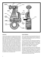
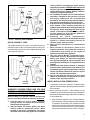
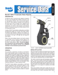
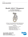
SD-05-1269
®
Bendix® ASA-5™ Automatic Slack Adjuster
DESCRIPTION
The Bendix® ASA-5™ sure stroke automatic slack adjuster
is designed for use on cam actuated drum brakes of the
type in use on most highway vehicles. Like a manual slack
adjuster, the ASA-5™ slack adjuster multiplies and transforms the linear force of the air actuator into a rotational
force or torque which is used to apply the foundation brake.
Additionally, the ASA-5™ slack adjuster automatically
adjusts the clearance between the brake lining and drum to
compensate for wear.
YOKE
YOKE PIN
LINK PIN
LINK
BOOT
A variety of ASA-5™ slack adjuster configurations are offered
including both straight arm and 5/8" yoke offset models.
The ASA-5™ slack adjuster is offered in arm lengths of 5,
5-1/2 and 6 inches and worm gear splines to accommodate
the standard 1-1/4" and 1-1/2", SAE 10C as well as the
Rockwell 24 and 28 tooth and Propar 37 tooth splines.
LUBE
FITTING
Either of two yoke designs (easy-on and quick connect) in
combination with an external manual adjuster hex provides
convenient installation and maintenance of the ASA-5™ slack
adjuster.
OPERATION
WORM
GEAR
GENERAL
The automatic adjustment provided by the Bendix® ASA-5™
slack adjuster results in consistent brake lining to drum
clearance and brake actuator stroke. The key to its operation is the ability to complete the brake adjustment during
the early part of each brake application and to cease adjusting as resistance to brake cam rotation begins to build.
This aspect of the adjuster mechanism’s operation prevents
over-adjustment due to: lining compression, actuator bracket
deflection, drum and foundation brake component distortion, or brake component wear.
The ASA-5™ slack adjuster incorporates a clutch-type
adjuster mechanism that continuously adjusts in very small
increments as lining and drum wear occurs. The adjustments made by the ASA-5™ slack adjuster are, therefore,
not in specific increments relative to actuator stroke.
APPLICATION
When the brakes are applied, the linear travel of the brake
actuator’s push rod causes the ASA-5™ slack adjuster to
FIGURE 1 - ASA-5™ AUTOMATIC SLACK ADJUSTER
rotate the foundation brake camshaft which in turn begins
to force the brake shoes into contact with the drum. When
the ASA-5™ slack adjuster rotates, the yoke assembly pivots on the yoke pin causing the link to be pulled upward.
The “teeth” on the link mesh with the adjuster mechanism
pinion and as the link is pulled it travels first through its free
play and then the pinion is rotated. Rotation of the pinion is
transmitted through the clutch spring to the worm and shaft.
Worm and shaft rotation results in worm gear rotation which
in turn adjusts (or repositions) the brake camshaft.
When the foundation brake shoes contact the drum, the
camshaft begins to resist rotation and friction between the
worm gear and worm builds, preventing further rotation of
the worm. Brake adjustment ceases at this point and further rotation of the ASA-5™ slack adjuster will cause the
pinion and clutch spring to slip. The “free play” between the
link teeth and pinion results in a predetermined lining to
drum clearance.
1
YOKE
YOKE PIN
ADAPTER
BUSHING
LINK PIN
CLUTCH
SPRING
WORM
ANTIREVERSE
SPRING
BOOT
LUBE
RELIEF
OPENING
FREE
PLAY
PINION
SPRING
RETAINER
WORM
GEAR
MANUAL
ADJUSTER
HEX
LUBE
FITTING
FIGURE 2 - SECTIONAL VIEW OF PROFILE AND END
RELEASE
YOKE DESIGNS
When the brake application is released, the brake actuator
push rod returns the ASA-5™ slack adjuster to the released
position. During release, the ASA-5™ slack adjuster rotates
back toward the actuator causing the brake camshaft to
again rotate, but in the opposite direction, and the brake
shoes begin to move away from the drum. As the ASA-5™
slack adjuster rotates back to the release position the yoke
again pivots causing the link to be pushed downward into
the slack adjuster body. The “free play” between the link
teeth and pinion is taken up during the initial part of the
release. Continued movement of the ASA-5™ slack adjuster
toward the released position causes the link to rotate the
pinion. The anti-reverse spring prevents counterclockwise
rotation of the shaft and worm causing the pinion and clutch
spring to slip. The gripping action of the anti-reverse spring
and slippage of the clutch spring during release is due to
the direction of the coil windings of each.
ASA-5™ slack adjusters may be equipped with either of two
yoke designs. Both are designed to permit installation or
removal of the slack adjuster along with its yoke body and
its attached adjusting linkage.
2
The brake actuator push rod must thread into the adapter a
minimum of 1/2 inch and must not extend more than 7/64
inch beyond the other end of the adapter. The yoke adapters
(quick connect & easy-on) have either a 1 or 1-1/4 inch hex to
allow tightening of the brake actuator push rod jam nut.
EASY-ON YOKE (REFER TO FIGURE 3)
The easy-on yoke assembly consists of an adapter which
is threaded internally to match the push rod threads and
externally to match female threads in the yoke. A special
extended yoke adapter is also available as a separate service item. The extended adapter is 1/2 inch longer than the
standard and is primarily intended for use when the existing brake actuator push rod is too short.
PUSH ROD
1-5/16"
YOKE
3.
4.
JAM NUT
MOUNTING
STUD
ADAPTER
3/8" OUT
5.
FIGURE 3 - EASY-ON YOKE ASSEMBLY
QUICK-CONNECT YOKE
6.
The adapter bushing in this case is threaded internally to
match the push rod, but is designed to slide into the yoke.
A retainer ring is used to secure the adapter bushing in the
yoke. (Refer to Figure 4)
7.
8.
PUSH ROD
RETAINING RING
YOKE
1"
9.
JAM NUT
10.
MOUNTING
STUD
ADAPTER
BUSHING
FLUSH
FIGURE 4 - QUICK-CONNECT YOKE ASSEMBLY
WARNING! PLEASE READ AND FOLLOW
THESE INSTRUCTIONS TO AVOID
PERSONAL INJURY OR DEATH:
When working on or around a vehicle, the following
general precautions should be observed at all times.
1. Park the vehicle on a level surface, apply the
parking brakes, and always block the wheels.
Always wear safety glasses.
2. Stop the engine and remove ignition key when
working under or around the vehicle. When
working in the engine compartment, the engine
should be shut off and the ignition key should be
removed. Where circumstances require that the
engine be in operation, EXTREME CAUTION should
be used to prevent personal injury resulting from
contact with moving, rotating, leaking, heated or
electrically charged components.
Do not attempt to install, remove, disassemble or
assemble a component until you have read and
thoroughly understand the recommended
procedures. Use only the proper tools and observe
all precautions pertaining to use of those tools.
If the work is being performed on the vehicle’s air
brake system, or any auxiliary pressurized air
systems, make certain to drain the air pressure from
all reservoirs before beginning ANY work on the
vehicle. If the vehicle is equipped with an AD-IS™
air dryer system or a dryer reservoir module, be
sure to drain the purge reservoir.
Following
the
vehicle
manufacturer’s
recommended procedures, deactivate the electrical
system in a manner that safely removes all
electrical power from the vehicle.
Never exceed manufacturer’s recommended
pressures.
Never connect or disconnect a hose or line
containing pressure; it may whip. Never remove a
component or plug unless you are certain all
system pressure has been depleted.
Use only genuine Bendix ® replacement parts,
components and kits. Replacement hardware,
tubing, hose, fittings, etc. must be of equivalent
size, type and strength as original equipment and
be designed specifically for such applications and
systems.
Components with stripped threads or damaged
parts should be replaced rather than repaired. Do
not attempt repairs requiring machining or welding
unless specifically stated and approved by the
vehicle and component manufacturer.
Prior to returning the vehicle to service, make
certain all components and systems are restored
to their proper operating condition.
INITIAL INSTALLATION PREPARATION
1. If necessary, remove the manual or automatic slack
adjuster currently installed, including the brake chamber
yoke assembly.
2. Before mounting the ASA-5™ slack adjuster on the
camshaft, check the brake chamber push rod length to
determine whether shortening or replacement is required.
To accomplish this:
A. With the brake chamber in the released position,
place a square (or equivalent object) so that one edge
is parallel to the actuator push rod while the other
edge bisects the brake camshaft. Measure the distance from the push rod end to the vertical edge of
the square and compare it to the values in Figure 5.
3
B. If the measurement is less than the minimum shown
in Figure 5, the brake actuator push rod must be
shortened. If the measurement is greater than the
maximum values, the brake actuator push rod may
require replacement. The extended adapter, available
as a separate service part (5/18-18 pc. no. 297700
and 1/2-20 pc. no. 297701) may avoid the need to
replace the brake actuator push rod. The extended
adapter is available for the easy-on yoke assembly
only.
3. Inspect the foundation brake, brake chamber and related components. Make certain the camshaft bushings
and seals are not excessively worn. Lubricate the camshaft bushings. Check the brake chamber bracket for
cracks and excessive corrosion. The brake actuator push
rod should not be loose or bent and the return spring
should be firm. Replace parts that are suspect.
4. Wire brush the foundation brake camshaft to loosen
contamination and wipe clean. Depending on
environmental conditions, an application of anti-seize
compound to both the camshaft and worm gear spline
may facilitate later slack removal.
INSTALLATION
1. Select the proper ASA-5™ slack adjuster.
2. Install the ASA-5™ slack adjuster on the brake camshaft.
3. If the ASA-5™ slack adjuster has the easy-on yoke (see
Figure 3), position the brake actuator push rod jam nut
approximately 1-5/16 inches from the end of the brake
actuator push rod. Thread the easy-on yoke adapter on
the brake actuator push rod until it is approximately 3/8
inch from the end of the brake actuator push rod end.
Turn the ASA-5™ slack adjuster manual adjustment hex
clockwise until the adapter extends into the threaded
bore of the yoke approximately 1/8 inch. Thread the
adapter into the yoke and tighten to 10 foot pounds.
The installation angle of a properly installed ASA-5™ slack
adjuster:
Slack Adjuster
Arm Length
5"
5.5"
6"
Angle
99°-113°
98°-111°
90°-109°
BRAKE ACTUATOR
PUSH ROD
SQUARE
INSTALLATION ANGLE
DISTANCE
"A"
MOUNTING
STUD
SLACK
ADJUSTER
ARM
LENGTH
5"
5-1/2"
6"
"A" STD.
QUICK CONNECT
OR EASY-ON
ADAPTER
1-15/16" - 3-1/32"
1-15/16" - 3-3/16"
"A"
EXTENDED
EASY-ON
ADAPTER
2-7/16" - 3-17/32"
2-7/16" - 3 11/16"
1-3/16" - 3-3/16"
1-11/16" - 3-11/16"
FIGURE 5 - MEASURING THE BRAKE ACTUATOR PUSH
ROD
4
4. If the ASA-5™ slack adjuster has the quick connect yoke
(see Figure 4), position the brake actuator push rod jam
nut approximately 1 inch from the end of the brake
actuator push rod. Thread the quick connect adapter
bushing on the brake actuator push rod until it is flush
with the end of the brake actuator push rod. Install the
retaining ring on the adapter bushing, making certain it
is in the adapter bushing groove. Turn the ASA-5™ slack
adjuster manual adjustment hex clockwise until the
adapter bushing begins to enter the yoke. Fully compress the retaining ring “legs” and continue turning the
ASA-5™ slack adjuster manual adjustment hex until the
adapter bushing is completely in the yoke.
Allow the retaining ring to expand into the corresponding
groove in the yoke. Make certain the retaining ring is
seated in both the yoke and the adapter bushing groove
by manually pulling the ASA-5™ slack adjuster arm,
attempting to separate the adapter bushing and yoke.
5. Run the brake actuator push rod jam nut down against
the adapter or adapter bushing. Hold the adapter or
adapter bushing hex with a wrench and tighten the jam
nut to 300-400 inch pounds for the 1/2"-20 thread and
400-600 inch pounds for the 5/8"-18 thread.
6. Manually adjust the brakes.
Note: The vehicle brakes should be adjusted using the
vehicle or brake manufacturer’s recommendation. If they
are not available, the following procedure can be used:
BRAKE ADJUSTMENT
Rotate the manual adjustment hex clockwise until the linings are snug against the drum. Turn the adjustment hex
counterclockwise 1/4 turn. Pull the actuator push rod to
confirm that approximately 1/2 inch of push rod free stroke
exists. Apply 85 psi and check that the push rod stroke is
below the readjustment Limit. If the stroke exceeds the
readjustment limit, check the condition of the foundation
brake. Refer to Brake Maintenance Inspection.
7. Manually uncage the spring brakes before returning the
vehicle to service.
8. With the ASA-5™ slack adjuster installed, check to ensure clearance requirements with the brake fully released
and at the actuator’s maximum stroke. Also consider
clearances with the vehicle suspension springs depressed to the jounce bumpers, as well as in rebound.
PREVENTIVE MAINTENANCE
Important: Review the Bendix Warranty Policy before performing any intrusive maintenance procedures. A warranty
may be voided if intrusive maintenance is performed during
the warranty period.
No two vehicles operate under identical conditions, as a
result, maintenance intervals may vary. Experience is a
valuable guide in determining the best maintenance interval
for air brake system components. At a minimum, the ASA-5™
slack adjuster should be inspected every 6 months or 1500
operating hours, whichever comes first, for proper operation. Should the ASA-5™ slack adjuster not meet the
elements of the operational tests noted in this document,
further investigation and service of the adjuster may be
required.
Visually check for physical damage such as broken air lines
and broken or missing parts.
Every 25,000 miles, or 3 months, or 500 operating hours or
at the time of routine vehicle chassis lubrication, whichever
occurs first, the following steps should be followed (Also
observe any shorter brake adjustment inspections or maintenance intervals specified by the vehicle manufacturer):
1. Lubricate the automatic slack adjuster through the lube
fitting with a quality multipurpose chassis lubricant
(N.L.G.I. Grade 1 or 2).
2. Perform the In Service Inspection described in this
manual.
IN SERVICE INSPECTION
1. Apply and release the vehicle brakes several times while
observing the ASA-5™ slack adjuster. The ASA-5™ slack
adjuster and brake actuator should move freely without
binding or interference and should return to the full released position. Observe the looseness that exists
between the yoke and adapter bushing and the yoke
and link pins and their mating parts (yoke, body, link).
Replace these parts if looseness appears excessive.
Make certain the brake actuator push rod jam nut is
tight against the yoke adapter.
2. Inspect the ASA-5™ slack adjuster for physical damage
paying particular attention to the link, boot and yoke.
Inspect for bent, broken, loose or misaligned brake actuator push rods and cracked or damaged brake actuator
brackets. Repair or replace any components found to
be damaged.
3. Measure the brake actuator push rod stroke while making an 80-90 psi service brake application. Actuator push
rod strokes should not exceed the values shown in the
following actuator stroke tables. The correct pressure
for this test can be achieved as follows. Build the system pressure up to 100 psi reading on the vehicle gage.
Shut the engine off. Fan the brakes to attain a 90-95 psi
reading. Make and hold a full brake application while the
strokes are checked.
STANDARD STROKE ACTUATOR STROKE TABLE
Brake
Actuator Size
30
24
Recommended
Maximum
Operating Stroke
2"
1-3/4"
20
16
1-3/4"
1-3/4"
12
1-3/8"
LONG STROKE ACTUATOR STROKE TABLE
Brake
Actuator Size
30LS
24L
Recommended
Maximum
Operating Stroke
2-1/2"
2"
24LS
20L
2-1/2"
2"
16L
2"
4. The Bendix® SureStroke™ indicator is also available as
a visual stroke indicator. The SureStroke™ indicator is
a metal bracketing system that bolts onto the brake
chamber and allows drivers to check the indicator for
operating stroke.
Lubricate the slack adjuster until clean lubricant flows
from the grease relief opening in the boot.
5
ADJUSTER HEX
ROTATES
CLOCKWISE
DURING
ADJUSTMENT
STRAIGHT
LINE SCRIBED
ACROSS HEX
AND BODY
the application and remain stationary during release. No
counterclockwise rotation of the hex should be observed.
The amount of clockwise rotation (adjustment) will
decrease progressively as the brake nears proper
adjustment. If the ASA-5 ™ slack adjuster fails to
perform as described, it will be necessary to repair or
replace it.
4. Manually readjust the ASA-5™ slack adjuster being
tested before returning the vehicle to service. (See section Installation, Step 6)
Note: While it is possible to use the automatic adjustment
feature of the ASA-5™ slack adjuster to bring the brake back
into adjustment, it will require numerous applications and
COMPLETE RELEASES (the number of applications depends on how much the slack was de-adjusted).
BRAKE MAINTENANCE INSPECTION
The following test can be used to inspect the maintenance
condition of the foundation brake and to determine how much
of the chamber stroke is caused by the condition of the
foundation brake.
FIGURE 6 - TESTING ADJUSTER MECHANISM
1. Chock wheels to keep vehicle from moving.
2. Raise axle so wheel can be rotated.
If the actuator stroke exceeds those shown, inspection of
the foundation brake and/or the automatic slack should be
completed. Maintenance of the foundation brake may be a
factor in the long stroke conditions. Inspecting the foundation brake per the Brake Maintenance Inspection presented
in this manual should determine how much of the long stroke
condition is caused by the condition of the foundation brake.
The ASA-5™ slack adjuster can be tested using the instructions presented in this manual under Testing the ASA-5™
Adjuster Mechanism.
3. Adjust slack adjuster to produce light brake drag with
wheel rotation.
4. Apply brake to 80-90 psi and measure stroke (See Item
3 of In Service Inspection for pressure tips).
5. If stroke significantly exceeds the values shown in the
chart, the brake may be out of the norm and brake maintenance may be required.
TESTING THE ASA-5™ ADJUSTER MECHANISM
12 X 5.0"
12 X 5.5"
15"x4"
Front
Brake
1/2"
1/2"
The following test can be made to determine if the ASA-5™
adjuster mechanism is functioning properly.
16 X 5.0"
16 X 5.5"
5/8"
3/4"
1/2"
1/2"
N/A
N/A
16 X 6.0"
20 X 5.0"
7/8"
5/8"
5/8"
1/2"
N/A
3/8"
20 X 5.5"
20 X 6.0"
3/4"
7/8"
5/8"
3/4"
1/2"
5/8"
24 X 5.0"
24 X 5.5"
N/A
N/A
5/8"
5/8"
1/2"
5/8"
24 X 6.0"
30 X 5.0"
N/A
N/A
3/4"
3/4"
5/8"
5/8"
30 X 5.5"
30 X 6.0"
N/A
N/A
7/8"
1"
3/4"
7/8"
1. With the brakes released and the vehicle wheels blocked,
de-adjust the brakes by rotating the manual adjustment
hex counterclockwise approximately 1/2 to 1 revolution.
Note: Considerable torque is required to rotate the
manual adjustment hex counterclockwise and should
be considered normal. The required torque may be as
high as 70 foot pounds.
2. Using a straight edge, scribe a line across the manual
adjustment hex head and slack adjuster body. (Refer to
Figure 6).
3. Apply and COMPLETELY RELEASE the service brakes
several times while observing the manual adjustment
hex and the scribed line. The ASA-5™ slack adjuster
manual adjustment hex should rotate clockwise during
6
AL Factor
16.5"x7"
Tractor, Truck
or Bus Brake
N/A
N/A
16.5"x7"
Trailer
Brake
N/A
N/A
ASA-5™ SLACK ADJUSTER REMOVAL
Note: Make certain the vehicle has been prepared according to the instructions under the heading WARNING!
PLEASE READ.
1. If the ASA-5™ slack adjuster is equipped with the easy-on
yoke assembly illustrated in Figure 3:
A. Loosen the brake actuator push rod jam nut and run
it back on the brake actuator push rod approximately
5/8 inch.
1. Clamp the ASA-5™ slack adjuster ARM in a bench vise.
Do not clamp across the portion of the body that contains the adjuster assembly or worm gear. Using a wire
brush, thoroughly clean the exterior of the slack adjuster
paying particular attention to the area around the manual
adjustment hex and its retaining ring. Wipe all loose
contaminants away before proceeding.
2. Remove the cotter pins and washers from the yoke pin
and link pin.
B. Loosen the easy-on yoke adapter and run it back on
the brake actuator push rod until it is free of the yoke.
3. Remove the yoke pin and link pin and separate the yoke
from the ASA-5™ slack adjuster.
C. Rotate the manual adjustment hex counterclockwise
until the ASA-5™ slack adjuster is clear of the brake
actuator push rod.
4. If the ASA-5™ slack adjuster has a yoke pin bushing,
press it out of the slack adjuster arm.
Note: Considerably more torque is required to rotate the
manual adjustment hex counterclockwise than is necessary to rotate it clockwise. The torque may be as high as
70 foot pounds.
™
2. If the ASA-5 slack adjuster is equipped with the
quick-connect yoke assembly illustrated in Figure 4:
A. Rotate the ASA-5™ slack adjuster's manual adjustment hex counter-clockwise until the brake actuator
push rod just begins to move out of the actuator.
B. Pinch the legs of the retaining ring together and pull
the ASA-5™ slack adjuster away from the brake
actuator push rod until the adapter bushing is free of
the yoke. Remove the retaining ring from the adapter
bushing.
C. Rotate the manual adjustment hex counter clockwise until the ASA-5™ slack adjuster is clear of the
brake actuator push rod.
3. Remove the ASA-5™ slack adjuster from the camshaft
of the foundation brake by removing the retaining clip
and any spacers or washers that may be present.
DISASSEMBLY
GENERAL
A reasonable level of cleanliness should be observed when
working on the ASA-5™ slack adjuster. Clean the exterior
before disassembly.
5. No further disassembly of the ASA-5™ slack adjuster is
permitted.
CLEANING AND INSPECTION
1. Inspect the worm gear camshaft splines for damage. If
damaged, replace the ASA-5™ slack adjuster.
2. Clean and inspect the yoke pin and link pin holes in the
yoke, adjuster link and slack adjuster body. The holes
should be visually round with no perceptible “egg shaping.” A new yoke pin and link pin can be used to make
this inspection. If this condition is noted, the affected
part must be replaced.
3. Clean out the retaining ring grooves in the yoke.
REASSEMBLY
1. If the ASA-5™ slack adjuster uses a yoke pin bushing,
press it into the slack adjuster arm.
2. Depending on environmental conditions an application
of anti-seize compound to both the yoke and link pins
may facilitate later removal. Install the yoke and secure
it to the ASA-5™ slack adjuster body and link using the
yoke pin and link pin. Note: Install the yoke and link
pins from the direction as shown in Figure 7. Install washers and cotter pins in the yoke pin and link pin, and
secure each. Bend each leg of the cotter pins to a minimum of 25 degrees, creating an included angle of at
least 50 degrees between the legs.
LUBRICATION
CHANNEL
LUBRICATION
GROOVE
The following disassembly and assembly procedure is presented for reference purposes and presupposes that a
rebuild or repair of the ASA-5™ slack adjuster is being undertaken. Several replacement parts and maintenance kits
are available which do not require full disassembly. The
instructions provided with these parts and kits should be
followed in lieu of the instructions presented here.
CAMSHAFT
SPLINES
FIGURE 8 - WORM GEAR LUBRICATION
7
3. Lubricate the automatic slack adjuster through the lube
fitting with a quality multipurpose chassis lubricant
(N.L.G.I. Grade 1 or 2). Lubricate the slack adjuster until clean lubricant flows from the grease relief opening in
the boot.
™
Note: This pre-installation lubrication on those ASA-5
slack adjuster’s equipped with a lubrication groove cut
in the splines of the worm gear requires the temporary
insertion of a “dummy camshaft spline” in the worm gear,
or the lubrication of these units must be performed with
the slack adjuster installed on the brake camshaft.
(Refer to Figure 8.)
RETROFITTING THE ASA-5™ SLACK
ADJUSTER
PREPARATION
The Bendix® ASA-5™ automatic slack adjuster can replace
a manual slack or competitive automatic slack adjuster
provided some considerations are kept in mind:
1. Excessive duty cycles, high application pressures and
brake force compounding can result in reduced slack
adjuster durability.
2. Determine that the AL factor of the vehicle to be retrofitted is 195 or less. To determine the AL factor multiply
the slack adjuster arm length (from the center of the
cam spline to the center of the yoke pin hole in use)
times the brake chamber size. Example: a type 30 brake
chamber connected to a 6 inch arm slack adjuster, A =
30 square inches, L = 6 inches; therefore, 30 x 6 = 180,
AL factor.
3. Make sure the foundation brake components are in good
condition. Excessive drum out-of roundness will result
in excessive lining wear. See the In Service Inspection
section contained in this manual.
4. In order to select the proper slack adjuster, choose an
ASA-5™ slack adjuster with the same arm length, spline
size, push rod thread size and offset as the slack adjuster
it is replacing.
5. When retrofitting the Bendix® ASA-5™ slack adjuster,
make certain to read the instructions packaged with all
service replacement ASA-5™ slack adjusters.
8
ASA-5™ SLACK ADJUSTER TROUBLESHOOTING CHART
SYMPTOMS
1. Brake Actuator stroke
is too long.
REMEDY
CAUSE
A. Loose actuator push rod
jam nut.
A. Reposition components and torque to
specification.
B. Excessive clearance
between adapter/adapter
bushing and yoke due to
wear.
B. Replace damaged or worn parts.
C. Excessive clearance
between components:
yoke pin—yoke
C. Replace worn parts.
link pin—link
yoke pin—body.
D. Damaged (worn)
splines on slack or
camshaft.
D. Replace damaged parts.
E. Weak or broken brake
actuator return springs.
Weak or broken brake
shoe return spring.
E. Replace weak or broken springs.
F. Worn or broken
foundation brake
components, including
camshaft bushings,
brake chamber bracket,
etc.
F. Repair or replace as required per In Service
Inspection.
G. ASA-5™ adjuster
mechanism not
functioning.
G. Lubricate, test adjuster mechanism, conduct in
service inspection, repair components as
necessary, replace.
H. Brake drum—worn,
excessively machined,
bell-mouthed,
excessive thermal
expansion.
H. Replace or repair as required.
I.
Damaged ASA-5™ slack
adjuster.
I.
J.
ASA-5™ slack adjuster
improperly installed.
J. Correct installation position.
Replace component(s) or slack adjuster.
9
ASA-5™ SLACK ADJUSTER TROUBLESHOOTING CHART (Continued)
SYMPTOMS
CAUSE
REMEDY
2. Brakes dragging—
apparent overadjustment
of brakes.
A. ASA-5™ slack adjuster
improperly installed. Too
close to actuator: brakes
can’t fully release.
A. Correct the ASA-5™ slack adjuster installation.
B. Loose actuator push rod
jam nut.
B. Reposition components and torque to
specification.
C. Spring brakes not fully
retracting.
C. Check spring brake release air pressure and
repair or replace air valving as necessary. Repair
or replace spring brake.
D. Broken foundation brake
components, including
camshaft bushings.
D. Repair or replace as required per In Service
Inspection.
E. Vehicle brake torque
imbalance. (More work
done by some brakes
than others, thermal
expansion of drums).
E. Check other brakes to insure they are working.
Check air pressure balance and threshold pressure (refer to Bendix publication BW-1555). Check
driver braking habits, e.g. use of trailer control
valve. Use same friction material on all axles.
F. Brake drum out-of-round,
excessive thermal
expansion.
F. Replace or repair as required.
G. Air system malfunction,
not exhausting
completely.
G. Inspect and correct.
H. New lining swells during
break-in.
H. Back-off adjustment until brakes are free.
10
11
12
BW1602 © 2004 Bendix Commercial Vehicle Systems LLC. All rights reserved. 3/2004 Printed in U.S.A.