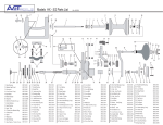
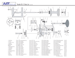
1
mustang
TM
English user manual
© 2012 R82 A/S. All rights reserved.
The R82 logo and the Mustang are registered trademarks of R82 A/S.
05.2012
CONTENTS
G
B
Mustang.............................................................................. 3
Security precautions........................................................... 4
Warranty............................................................................. 4
Tools................................................................................... 4
Ready for use..................................................................... 5
Chest support (accessory)................................................. 5
Height adjustment.............................................................. 6
Angling............................................................................... 6
Height adjustment of the chest support bar........................ 7
Adjustment of the chest support......................................... 7
Parking brakes................................................................... 8
Drag brakes........................................................................ 8
Anti-reverse wheel stops.................................................... 8
Directional Stabilizers......................................................... 9
Extension piece for chest support (accessory)................. 10
Cover for chest support (accessory)................................ 10
Head support (accessory) adjustment ............................. 11
Hip support (accessory) adjustment................................. 12
Abdominal support (accessory) adjustment..................... 13
Hand bar, anterior (accessory)......................................... 13
Arm prompts, anterior or posterior (accessories)............. 14
Arm rests, anterior (accessories)..................................... 14
Seat (accessory) adjustment............................................ 15
Sacrum support (accessory) adjustment.......................... 15
Sling seat (accessory) adjustment................................... 16
Storage pouch (accessory).............................................. 16
Guide bar (accessory) adjustment.................................. 17
Adjustment of leg separator (accessory).......................... 18
Height settings.................................................................. 19
Folding before transportation........................................... 20
Product Identification........................................................ 21
Care and maintenance..................................................... 22
Troubleshooting................................................................ 22
Measurements.................................................................. 23
Technical data.................................................................. 24
Manufacturer.................................................................... 24
Distributor......................................................................... 24
2
MUSTANG
We are pleased that you have chosen the R82 Mustang as your child's new walker.
The Mustang is a walking aid from R82, suitable for children needing supplementary
assistance with their daily walking. The Mustang can be used by e.g. CP children and
others with lack of balance and impairment of their motor function. The Mustang is
developed as a basic anterior walker but can also be used as a posterior gait trainer,
depending on the child’s level of ability.
The Mustang comes in 4 sizes. Size 1 is equipped with four 4” castors and is primarily intended for indoor use and can be used outside as well on level surfaces.
Size 2+3+4 are equipped with 4 solid wheels (200 x 50 mm) and is suitable for
both indoor and outdoor use.
This user manual is to assist the user/caregiver in proper use of the Mustang.
Therefore we recommend reading through this manual before use.
3
G
B
SECURITY PRECAUTIONS
•
•
•
•
•
•
•
•
•
Read this manual carefully before use and keep it for future reference. The user’s
safety may be affected if you do not follow the instructions in this manual.
Adjustments which are not described in this manual must only be made by authorized
R82 personnel.
This product is CE-marked which certifies that it meets all relevant European safety
requirements. The Mustang is tested and approved to EN 1985. Remove the CEmark when rebuilding the product or when using other than original R82 spare parts
and fittings.
The maximum service life of this product is 5 years when it is used on a daily basis.
Hereafter the product must be renovated (by R82 personnel) to extend the lifetime.
Never leave the user unattended in this product. Ensure permanent supervision by
an adult. Incorrect use of this product may cause serious injury to the user.
This product is constructed for one user only. Do not place more than one user in this product.
If the user is close to the max. load/height indication and has a lot of involuntary
movements e.g. rocking, a larger size with higher max. load should be considered.
Take care that all the fixations and adjustments are placed and fitted correctly and
checked before every use.
Do not place a user in the product if it has been standing in/exposed to the sun. For
the safety and comfort of the user the product must be moved away from the sun and
allowed to cool before use.
WARRANTY
G
B
R82 offers a 2-year warranty against defects in workmanship and materials and a 5-year
warranty on breakage of the metal frame caused by defects in welds. The warranty would
be adversely affected if the customer’s responsibility of servicing and/or daily maintenance
is not carried out according to the guidelines and intervals prescribed by the supplier and/
or stated in the manual. For further information, we refer to the R82 homepage/download.
The warranty can only be sustained if the R82 product is in use in the same country where
it was purchased and if the product can be identified by the serial number. The warranty
does not cover accidental damage, including damage caused by misuse or neglect. The
warranty does not extend to non-durable parts, which are subject to normal wear and
tear and need periodic replacement. The warranty is null and void if non-original R82
parts/accessories are used, or if the product is repaired or altered by anyone other than
an authorised R82 representative or by trained personnel officially recognised by R82 for
repair and maintenance of R82 products. R82 reserves the right to inspect the product
being claimed for and the relevant documentation before agreeing to the warranty claim,
and to decide upon whether to replace or repair the defective product. It is the customer’s responsibility to return the item being claimed for under warranty to the address of
purchase. The warranty is given by R82 or, subsequently, an R82 dealer.
TOOLS
Enclosed please find the 5 mm Allen key.
4
READY FOR USE
•
•
•
•
•
B
Remove the frame from the box
Remove the quick release bolts (A)
Unfold the frame (B)
Remove the protective foam tubes
Remount the quick release bolts (C)
A
Make sure that the Allen screws are tightened before using the Mustang. Frequently
check all screws and adjustments.
Be aware not to get your fingers caught in
the holes in the frame.
C
CHEST SUPPORT
(ACCESSORY)
E
Mounting
• Mount the outer tube and fasten the screws
(D) with the enclosed 5 mm Allen key.
• Mount the chest support and fasten the
screws (E) with the enclosed 5 mm Allen key.
D
When the locking pin (F) 'clicks' out, the
max. height setting for the chest support
has been reached.
F
'max.'
5
G
B
HEIGHT ADJUSTMENT
• Activate the handle (A) to height adjust the
chest support bar
Be careful not to get your fingers caught
when height adjusting the chest support.
A
ANGLING
• Turn the handle (B) to angle the chest support bar
G
B
Be careful not to get your fingers caught
when angling the chest support.
B
6
HEIGHT ADJUSTMENT OF
THE CHEST SUPPORT
BAR
B
A
Loosen the screw (A) using the enclosed 5 mm
Allen key to height adjust the chest support bar.
'max.'
When the locking pin (B) 'clicks' out, the
max. height setting for the chest support
has been reached.
C
'max.'
Make sure that the Allen screws are tightened before using the Mustang. Frequently
check all screws and adjustments.
DO NOT place the center bar beyond the
max mark indication! Make sure that both
allen screws (C) on the black center joint
are thightened before using the Mustang.
ADJUSTMENT OF THE
CHEST SUPPORT
B
C
• Loosen the screws (A) to width adjust the
chest support bar G
B
DO NOT place the chest support bars
beyond the max mark indication
A
• Loosen the screws (B) and (C) to adjust the
chest support pads individually. For easy access and dismount, we recommend not over
tightening the screws (C)
• Fasten the chest support with the straps and
buckles on the back (D)
'max.'
Make sure that the Allen screws are tightened before using the Mustang. Frequently
check all screws and adjustments.
Check all straps and buckles before every
use and replace any worn out parts before
using this product.
7
PARKING BRAKES
A
B
The Mustang is as standard equipped with parking brakes on all four wheels.
• Push down the button (A) firmly with your
foot to activate the brake
• Push down the button (B) to deactivate the
brake
Make sure that all four brakes are activated
before placing the user into the Mustang.
Check the effectiveness of the parking
brakes before every use. Contact your
local dealer for replacement of ineffective
parking brakes.
DRAG BRAKES
The Mustang is as standard equipped with drag
brakes on all four wheels.
• Fasten the handle (A) more or less to regulate the force required to propel the Mustang.
A
G
B
ANTI-REVERSE WHEEL
STOPS
The Mustang is as standard equipped with antireverse wheel stops on all four wheels.
• Push the wheel stops down to activate
• Push the wheel stops up to deactivate
A
The anti-reverse wheels stops only function with the directional stabilizers activated
8
DIRECTIONAL
STABILIZERS
The Mustang is as standard equipped with directional stabilizers on all four wheels. The directional stabilizers lock the wheels in a forward
facing direction.
1)To activate the directional stabilizers pull the
button (1A), turn it clockwise (1B), and release
it so it engages in the slot.
The button should then appear as shown in
(1C). This locks the front wheels in a forward
facing position only.
1
A
2)To deactivate the directional stabilizers pull
the button (2A), turn it counter-clockwise (2B)
so it no longer fits into the slot, and release it.
B
The button should then appear as shown in
(2C). This allows the front wheels to turn in
any direction.
C
2
G
B
A
B
C
9
EXTENSION PIECE
FOR CHEST SUPPORT
(ACCESSORY)
• Dismount the screw (A) to height adjust the
extension piece.
• Remount the screw (A) in one of the holes
in the extension piece (B)
A
Use the enclosed 5 mm Allen key to perform all
fittings
Make sure that the Allen screws are tightened before using the product. Frequently
check all screws and adjustments.
B
COVER FOR CHEST
SUPPORT (ACCESSORY)
G
B
For added comfort a cover can be mounted on
the chest support pads.
• Undo the velcro (A) and dismount the cover
e.g. for washing (40°)
Check all straps and buckles before every
use and replace any worn out parts before
using this product.
A
10
HEAD SUPPORT
(ACCESSORY)
ADJUSTMENT
A
• Angle adjustment of the head support (A)
• Height adjustment (B)
'max.'
DO NOT place the head support beyond
the max. mark indication
B
• Angle adjustment of the head support bar
system (C)
Use the enclosed 5 mm Allen key to perform all
fittings
C
Be careful not to get your fingers caught
when adjusting the head support
Make sure that all screws and handles are
tightened before use. Frequently check all
screws and handles
G
B
11
HIP SUPPORT
(ACCESSORY)
ADJUSTMENT
• Height adjustment (A)
• Height and width adjustment (B)
A
Use the enclosed 5 mm Allen key to perform all
fittings
B
DO NOT place the back support beyond
the max. mark indication
'max.'
Make sure that all screws and handles are
tightened before use. Frequently check all
screws and handles
G
B
12
ABDOMINAL SUPPORT
(ACCESSORY)
ADJUSTMENT
Max
65 cm
25.5 inch
Max
85 cm
33.5 inch
Height adjustment (A)
Height adjustment (B)
Max
MAXheight_Mustang.indd 1
A
Max
MAXheight_Mustang.indd 1
Use the enclosed 5 mm Allen key to perform all
fittings
18-08-2011 08:27:37
105 cm
41 inch
18-08-2011 08:46:31
130 cm
50.5 inch
B
MAXheight_Mustang.indd 1
BE AWARE of the max. height indication
shown on the frame.
18-08-2011 08:46:39
'max.'
Make sure that all screws and handles are
tightened before use. Frequently check all
screws and handles
HAND BAR, ANTERIOR
(ACCESSORY)
G
B
Height adjustment (A)
Depth adjustment (B)
Use the enclosed 5 mm Allen key to perform all
fittings
BE AWARE of the max. height indication
shown on the frame.
A
B
Max
65 cm
25.5 inch
Max
Make sure that all screws and handles are
tightened before use. Frequently check all
screws and handles
85 cm
33.5 inch
Max
MAXheight_Mustang.indd 1
18-08-2011 08:27:37
105 cm
41 inch
Max
MAXheight_Mustang.indd 1
18-08-2011 08:46:31
130 cm
50.5 inch
MAXheight_Mustang.indd 1
13
18-08-2011 08:46:39
ARM PROMPTS,
ANTERIOR OR
POSTERIOR
(ACCESSORIES)
A
• Angle and depth adjustment (A)
• Angle and depth adjustment (B)
• Rotational adjustment (C)
Use the enclosed 5 mm Allen key to perform all
fittings
Max
65 cm
25.5 inch
Max
85 cm
33.5 inch
Max
MAXheight_Mustang.indd 1
BE AWARE of the max. height indication
shown on the frame.
B
18-08-2011 08:27:37
105 cm
41 inch
Max
MAXheight_Mustang.indd 1
18-08-2011 08:46:31
130 cm
50.5 inch
MAXheight_Mustang.indd 1
Make sure that all screws and handles are
tightened before use. Frequently check all
screws and handles
C
18-08-2011 08:46:39
ARM RESTS, ANTERIOR
(ACCESSORIES)
• Angle and depth adjustment (A)
• Angle adjustment (B)
G
B
Use the enclosed 5 mm Allen key to perform all
fittings
A
B
BE AWARE of the max. height indication
shown on the frame.
Max
Make sure that all screws and handles are
tightened before use. Frequently check all
screws and handles
65 cm
25.5 inch
Max
85 cm
33.5 inch
Max
MAXheight_Mustang.indd 1
18-08-2011 08:27:37
105 cm
41 inch
Max
MAXheight_Mustang.indd 1
18-08-2011 08:46:31
130 cm
50.5 inch
MAXheight_Mustang.indd 1
18-08-2011 08:46:39
14
SEAT (ACCESSORY)
ADJUSTMENT
• Height adjustment (A)
Use the enclosed 5 mm Allen key to perform all
fittings
Make sure that the bracket from the seat is
placed far enough up on the chest support
bar before fastening.
Make sure that all screws and handles are
tightened before use. Frequently check all
screws and handles
√
A
SACRUM SUPPORT
(ACCESSORY)
ADJUSTMENT
A
G
B
• Height adjustment (A)
• Depth adjustment. Turn to loosen the handle
(B) and pull out the security lock (C) to dismount the support
DO NOT place the support beyond the
max. mark indication
C
Make sure that all screws and handles are
tightened before use. Frequently check all
screws and handles
'max.'
15
B
SLING SEAT
(ACCESSORY)
ADJUSTMENT
Only for size 1+2
• Pull the straps to adjust the height (A)
• Undo the buckles for easy removal (B)
B
Check all straps and buckles before every
use and replace any worn out parts before
using this product
A
STORAGE POUCH
(ACCESSORY)
G
B
A
The storage pouch can be placed various places
on the frame and is fastned with velcro (A)
Undo the velcro and dismount the pouch e.g.
for washing (40°).
Check all straps and buckles before every
use and replace any worn out parts before
using this product
16
GUIDE BAR
(ACCESSORY)
ADJUSTMENT
Angle adjustment (A)
Loosen the screw (B) and push in the security
split (C) to dismount the guide bar
A
Use the enclosed 5 mm Allen key to perform all
fittings
DO NOT use the guide bar for lifting. Incorrect use could result in serious injury
to the user
B
C
Make sure that the Allen screws are tightened before using the product. Frequently
check all screws and adjustments.
Be careful not to get your fingers caught
when adjusting the guide bar
G
B
17
ADJUSTMENT OF
LEG SEPARATOR
(ACCESSORY)
Mounting (A)
Use the enclosed 5 mm Allen key to perform all
fittings
Make sure that the bar from the leg separator is fully mounted into the bracket
before fastening
A
G
B
18
Please be careful not to get your fingers
or the users toes caught between the leg
separator and the floor or between the leg
separator and the seat
Make sure that the Allen screws are tightened before using the product. Frequently
check all screws and adjustments
HEIGHT SETTINGS
The Mustang comes as standard with the height
settings in Hole 2. Various height settings can be
made in order to lower or heighten the Mustang.
3.
2.
1.
1) Remove the quick release (A)
2)Loosen the screws (B)
3) Remove the screw (C)
4)Adjust the frame and remount the screw (C)
in one of the holes in the frame. Fasten the
screws (B) and remount the quick release (A).
Make sure that all screws and handles are
tightened before use. Frequently check all
screws and handles
Be aware not to get your fingers caught in
the holes in the frame.
A
C
Size 1
Hole 1
Hole 2
B
Size 2
Hole 3
Hole 1
Hole 2
Hole 3
Height, floor to axila
46½-65 cm
43-65 cm
38-65 cm
61½-80 cm
60-80 cm
59-80 cm
Height, floor to axila, with arm prompts mounted
51-65 cm
47½-65 cm
42-65 cm
65½-80 cm
64-80 cm
63-80 cm
Seat height from floor
26-37½ cm
17-35 cm
11-29 cm
34½-51½ cm
33-50 cm
32-49 cm
Angle, chest support bar
5° to 35°
0 to 30°
-5 to 20°
5° to 35°
0 to 30°
-10° to 20°
The Mustang is measured with the centre bar in vertical position
Size 3
Size 4
Hole 1
Hole 2
Hole 3
Hole 1
Hole 2
Height, floor to axila
72-105 cm
71-105 cm
69-105 cm
89-130 cm
87-130 cm
85-128½ cm
Height, floor to axila, with arm prompts mounted
76½-105 cm
75½-105 cm
73½-109½ cm
93½-130 cm
91½-130 cm
89½-130 cm
Seat height from floor
34-70 cm
31-68 cm
29-66 cm
50-85½ cm
49-85 cm
46-82 cm
Angle, chest support bar
-3° to 45°
-6° to 40°
-8° to 48°
-5° to 33°
-7° to 35°
-10° to 29°
The Mustang is measured with the centre bar in vertical position
19
Hole 3
G
B
FOLDING BEFORE
TRANSPORTATION
• Remove the chest support
• Remove the quick release pins (A) on both
sides
• Press down the handle (B) to fold the frame
• Replace the quick release pins for safe storage during transportation.
Be aware not to get your fingers caught
when folding the frame.
Make sure both the Mustang and all accessories have been securely fastened before
transportation in motor vehicles.
A
B
G
B
20
PRODUCT
IDENTIFICATION
A) Serial number
The label is located on the underside of the
frame by the right rear wheel.
C
B) Manufacturer
A
The label is located on the underside of the
frame by the left rear wheel.
B
C)Max user height (floor to axila)
The label is located on the left side of the
centre bar.
A
Date: YYYY-MM-DD Max.Load: XX KG
Date: xx-xx-xx
Load: xx kg
SN: Serial no:
XXXXXX xxxx-xx-xxxxxx-xxx
Ver.: XX
Art.No:
XXXXXX xxxxxxx
Article no:
Product - Size X
(01)0570729530134(21)256829
B
Parallelvej 3
DK-8751 Gedved
G
B
www.R82.com
Made in Denmark
C
Max
65 cm
25.5 inch
size 1
Max
85 cm
33.5 inch
size 2
Max
105 cm
41 inch
size 3
MAXheight_Mustang.indd 1
MAXheight_Mustang.indd 1
18-08-2011 08:27:37
Max
130 cm
50.5 inch
size 4
18-08-2011
08:46:31
MAXheight_Mustang.indd
1
21
18-08-2011 08:46:39
CARE AND MAINTENANCE
FRAME
Check all screws on a regular basis. Also, it is important to keep the Mustang clean, both for sanitary
reasons and to prolong the life of the product. Take special care to clean the holes for the directional stabilizers. Wash the frame with car shampoo or dish washing liquid. If the Mustang is overly dirty, a grease
remover may be used.
INSPECTION
It is important to tighten all screws on the walking aid on a regular basis. All screws which secure the accessories must be checked, at least once a month. Check the effectiveness of the parking brakes before
every use. Contact your local dealer for replacement of ineffective parking brakes. Also, it is important to
check for any cracks or faults in the frame, PVC parts, etc.
REPAIR
If there is a problem with your Mustang you should contact your dealer at once. Defective Mustangs should
not be used. If your Mustang needs reconditioning or repair, only original R82 parts may be used. Accessories or available spare parts which are broken can be sent to R82 for repair. If there are problems with
the frame, the whole Mustang needs to be returned to R82 for repair. R82 will not be held responsible for
damage or injury caused by use of non-original parts or repairs made by a non-authorized R82 person.
TROUBLESHOOTING
Problem
G The walking frame seems
B loose
Solution
Tighten all screws.
The Mustang is too hard/easy
to propel
Make sure the parking brakes and anti-reverse wheel stops have been
deactivated. Loosen/fasten the drag brake handle to regulate the force to
propel the Mustang.
The anti-reverse wheel stops
do not function
Remove dirt from the unit and clean the wheels.
The pedal for height adjustment does not function
Remove dirt from the unit.
The height adjustment does
not function
Contact your local dealer for adjustment or replacement of the gas strut.
The parking brakes does not
function
Remove dirt from the unit. Contact your local dealer for replacement of the
parking brakes.
22
a1
I
G1
G
H
MEASUREMENTS
Width, total (G)
Width, inside frame (G1)
Width, inside chest support (G2)
Length, total (H)
Height, total (I)
Seat height above floor (seat = accessory)
Width between handles (handles = accessory)
Height from floor to handles (handles = accessory)
Angle range of centre bar (a1)
Turning radius
User height, floor to axila
Weight, standard without accessories
Max. load / user weight
Size 1
52 cm (20¼”)
38 cm (14¾”)
16½-23½ cm (6½-9”)
75 cm (29¼”)
65 cm (25½”)
17-35 cm (6½-13½”)
14-35 cm (5½-13½”)
37-58 cm (14½-22½”)
0-30°
45 cm (17½")
38-65 cm (14¾-25½”)
10 kg (22 lb)
30 kg (66 lb)
Size 2
63 cm (24½”)
45 cm (17½”)
23½-27 cm (9-10½”)
90 cm (35”)
85 cm (33½”)
33-50 cm (12¾-19½”)
14-35 cm (5½-13½”)
51-71 cm (20-27¾”)
0-30°
55 cm (21½")
60-85 cm (23½-33½”)
14 kg (31 lb)
40 kg (88 lb)
Width, total (G)
Width, inside frame (G1)
Width, inside chest support (G2)
Length, total (H)
Height, total (I)
Seat height above floor (seat = accessory)
Width between handles (handles = accessory)
Height from floor to handles (handles = accessory)
Angle range of centre bar (a1)
Turning radius
User height, floor to axila
Weight, standard without accessories
Max. load / user weight
Size 3
65 cm (25½”)
50 cm (19½”)
30-40 cm (11¾-15½”)
100 cm (39”)
105 cm (41”)
45-68 cm (17½-26½”)
14-60 cm (5½-23½”)
65-90 cm (25½-35½”)
0-25°
55 cm (21½")
70-105 cm (27½-41")
18 kg (40 lb)
60 kg (132 lb)
Size 4
70 cm (27½”)
56 cm (22”)
30-40 cm (11¾-15½”)
110 cm (43”)
130 cm (50½”)
62-84 cm (24-32¾”)
14-60 cm (5½-23½”)
81-125 cm (31½-50”)
0-25°
62 cm (24¼")
87-130 cm (34-50½”)
19 kg (42 lb)
80 kg (176 lb)
The Mustang is measured as standard delivered and with the centre bar in vertical position. Different settings may result in another set
of measurements. To accomplish some of the measurements above, a slight adjustment might be required. We supply various types of
accessories, which is why the weight is listed without.
23
G
B
TECHNICAL DATA
Frame: Powder lacquered Steel tubes
Plastic parts:
Glass fibre strengthened nylon / ABS
DISTRIBUTOR
MANUFACTURER
R82 A/S
Parallelvej 3
8751 Gedved
Denmark
Please find your distributor on www.R82.com
G
B
24