1
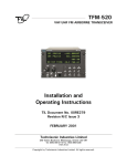
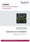
INSTALLATION MANUAL
KY 196B
VHF COMMUNICATIONS
TRANSCEIVER
MANUAL NUMBER 006--10570--0001
REVISION 1, JANUARY, 2000
WARNING
Prior to export of this document, review for export license requirement is
needed.
COPYRIGHT NOTICE
!
2000 Honeywell International Inc.
Reproduction of this publication or any portion thereof by any means without the express written permission of Honeywell International Inc. is prohibited. For further information contact the Manager, Technical Publications,
Honeywell International Inc., One Technology Center, 23500 West 105th
Street, Olathe, Kansas 66061. Telephone: (913) 782--0400
BENDIX/KING
KY 196B
VHF COMMUNICATIONS TRANSCEIVER
SECTION I
GENERAL INFORMATION
Paragraph
Page
1.1
INTRODUCTION
1--1
1.2
DESCRIPTION OF EQUIPMENT
1--1
1.3
TECHNICAL CHARACTERISTICS
1--1
1.4
UNITS AND ACCESSORIES SUPPLIED
1--4
1.5
ACCESSORIES REQUIRED, BUT NOT SUPPLIED
1--5
1.6
LICENSE REQUIREMENTS
1--5
1.7
INSTRUCTIONS FOR CONTINUED AIRWORTHINESS
1--6
SECTION II
INSTALLATION
2.1
GENERAL INFORMATION
2--1
2.2
UNPACKING AND INSPECTING EQUIPMENT
2--1
2.3
EQUIPMENT INSTALLATION
2--1
2.3.1
AVIONICS COOLING REQUIREMENTS
2--1
2.3.2
MOUNTING RACK INSTALLATION
2--2
2.3.3
ANTENNA INSTALLATION
2--2
2.3.4
CABLE HARNESS AND CONNECTOR ASSEMBLY
2--2
2.3.5
KY 196B INSTALLATION
2--3
2.3.6
MOLEX TERMINAL INSTRUCTIONS
2--5
2.4
POST INSTALLATION CHECKS
2--7
SECTION III
OPERATION
3.1
GENERAL INFORMATION
3--1
3.1.1
TURN ON
3--1
3.1.2
TRANSMIT INDICATOR
3--1
3.1.3
MODES OF OPERATION
3--1
3.1.4
REMOTE FREQUENCY TRANSFER
3--3
3.1.5
REMOTE CHANNEL INCREMENT
3--3
3.1.6
DIM SELECT
3--3
3.1.7
DISPLAY ADJUST MODE
3--3
10570I01.ZIPCDL
Rev 1 January/2000
Page i
BENDIX/KING
KY 196B
VHF COMMUNICATIONS TRANSCEIVER
TSO APPENDIX
ENVIRONMENTAL QUALIFICATION FORMS
Drawing No.
Page
004--02170--0082 . . . . . . . . . . . . . . . . . . . . . . . . . . . . . . . . . . . . . . . . . . . . TSO--1
LIST OF ILLUSTRATIONS
Figure
2--1 MOLEX TERMINALS AND TOOLS . . . . . . . . . . . . . . . . . . . . . . . .
2--2 HAND CRIMPER . . . . . . . . . . . . . . . . . . . . . . . . . . . . . . . . . . . . . . . .
2--3 CRIMP JAWS . . . . . . . . . . . . . . . . . . . . . . . . . . . . . . . . . . . . . . . . . . .
2--4 TERMINAL INSERTION . . . . . . . . . . . . . . . . . . . . . . . . . . . . . . . . . .
2--5 HAND CRIMPER INSERTION . . . . . . . . . . . . . . . . . . . . . . . . . . . .
2--6 CRIMPING PRESSURE ADJUSTMENT . . . . . . . . . . . . . . . . . . . .
2--7 CONNECTOR ASSEMBLY . . . . . . . . . . . . . . . . . . . . . . . . . . . . . . .
2--8 OUTLINE AND MOUNTING DRAWING . . . . . . . . . . . . . . . . . . . .
2--9 INSTALLATION ASSEMBLY DRAWING . . . . . . . . . . . . . . . . . . . .
2--10 KY 196B INTERCONNECT . . . . . . . . . . . . . . . . . . . . . . . . . . . . . .
2--11 DUAL KY 196B INTERCONNECT DIAGRAM . . . . . . . . . . . . . . .
2--12 KY 196B INTERCONNECT WITH KA 25A . . . . . . . . . . . . . . . . .
2--13 KY 196B PIN FUNCTION AND LOCATION DIAGRAM . . . . . . .
Page
2--4
2--5
2--5
2--6
2--6
2--7
2--9
2--11
2--13
2--15
2--17
2--19
2--23
3--1 KY 196B VHF COMMUNICATIONS TRANSCEIVER . . . . . . . . .
3--5
Page ii
10570I01.ZIPCDL
Rev 1 January/2000
BENDIX/KING
KY 196B
VHF COMMUNICATIONS TRANSCEIVER
SECTION I
GENERAL INFORMATION
1.1 INTRODUCTION
This manual contains information relative to the physical, mechanical, and electrical characteristics
of the BENDIX/KING KY 196B VHF Communications Transceiver. Installation and operating
procedures are also included. Information relative to the maintenance, alignment, and
procurement of replacement parts may be found in the KY 196B Maintenance/Overhaul Manual.
1.2 DESCRIPTION OF EQUIPMENT
The KY 196B VHF Comm Transceiver consists electrically of five sections: receiver, transmitter,
synthesizer, display circuitry, and the microprocessor board. The KY 196B operates at 28VDC and
features 16 Watts of transmitter power.
The KY 196B is available with 8.33 KHz or 25KHz receiver selectivity, diffused display lenses,
backlit bezel nomenclature, and operating ranges of 118.000 to 136.9916 MHz. See Paragraph
1.4 below for descriptions of specific flavors.
The KY 196B has the capability of programming up to nine memory channel frequencies for later
recall. Channel frequency information is stored in non -- volatile memory so the when the radio is
turned off and then back on, channel information is retained. Both units also have the capability
of remote transfer of Use and Standby frequencies, and remote recall of channel frequency
information.
1.3 TECHNICAL CHARACTERISTICS
SPECIFICATION
CHARACTERISTIC
TSO COMPLIANCE:
Transmitter:
KY 196B (flavors --0101, --0201)
TSO C37c, DO--186 Class 3
TSO C37c, DO--186a Class 5
Receiver:
KY 196B (flavors --0101, --0201)
TSO C38c, DO--186 Classes C & D
TSO C38c, DO--186a Class E
ENVIRONMENTAL DATA:
See TSO Appendix
PHYSICAL DIMENSIONS:
Height:
1.35 in (3.43 cm)
Width:
6.312 in (16.032 cm)
Depth (behind aircraft panel):
10.776 in (27.371 cm)
WEIGHT:
With rack
3.2 lbs (1.45 Kg), ¦0.2 lbs (0.09 Kg.)
Without rack
3.0 lbs (1.36 Kg), ¦0.2 lbs (0.09 Kg.)
MOUNTING:
10570I01.ZIPCDL
Rev 1 January/2000
Panel mounted, no shock mounting
required
Page 1-1
BENDIX/KING
KY 196B
VHF COMMUNICATIONS TRANSCEIVER
TEMPERATURE RANGE:
--20°C to +55°C with short time
operation at +70°C
POWER REQUIREMENTS:
KY 196B:
28VDC at 0.4A (Receive)
6.5A (Transmit)
FREQUENCY RANGE:
118.000 MHz to 136.9916 MHz in
8.33 KHz mode.
118.000 MHz to 136.975 MHz in 25
KHz mode
FREQUENCY STABILITY:
0.0005% from --20°C to +55°C
DESIGN:
All solid state, Printed circuit board
and point to point wiring.
FCC ID:
ASYKY196B
FCC EMISSION DESIGNATORS:
6K00A3E
6K00A9W
TRANSMITTER
POWER OUTPUT:
KY 196B:
16 Watts minimum
MODULATION:
70% modulation capability with 98% limiting.
Less than 15% distortion at 70% modulation.
SIDETONE OUTPUT:
Adjustable up to 100mW into 500Ω headphones
MICROPHONE:
Standard carbon dynamic mic containing
transistorized preamp. Must provide 100mVRMS
into 100Ω load.
HARMONIC CONTENT:
Greater than 60dB down from carrier.
HIGH TEMPERATURE PROTECTION: If the transmitter or modulator circuits become hot
enough to potentially hurt any components in the
transceiver, a protection circuit will automatically turn
down the transmitter power consumption and output
power to 4 Watts minimum.
DUTY CYCLE:
Page 1-2
1 minute on, 4 minutes off
10570I01.ZIPCDL
Rev 1 January/2000
BENDIX/KING
KY 196B
VHF COMMUNICATIONS TRANSCEIVER
RECEIVER
RECEIVER SENSITIVITY:
2µV (hard) shall produce not less than 6dB S+N/N
with 1KHz tone modulated 30% (with compressor
disabled).
RECEIVER SELECTIVITY:
Class C, D (flavors --0101, --0201)
6dB bandwidth at not less than 8.0 KHz on each
side. 40dB bandwidth with no more than 17.0 KHz
on each side. 60dB bandwidth with no more than
22.0 KHz on each side.
Class E (flavors --0101, --0201)
6 dB bandwidth at not less than 2.778 kHz on
each side.
60 dB bandwidth at not more than 7.37 kHz on
each side.
RECEIVER OUTPUT:
100mW minimum into 500Ω minimum.
AGC CHARACTERISTIC:
From 10 µV to 100,000 µV audio output will not
vary more than 3dB.
SQUELCH:
Automatic squelch (internally adjustable
carrier--to--noise setting) with manual disable.
SPURIOUS RESPONSES AND CROSS
MODULATION PRODUCTS:
INTERCOM INPUT:
10570I01.ZIPCDL
Rev 1 January/2000
At least 80dB down.
The mic is connected to the intercom input. The
receiver is operational and mic audio appears at
the audio output along with receive audio.
100mVRMS of mic audio into 100Ω is required
for 100mW output.
Page 1-3
BENDIX/KING
KY 196B
VHF COMMUNICATIONS TRANSCEIVER
1.4 UNITS AND ACCESSORIES SUPPLIED
A.
KY 196B VHF Comm Transceiver, PN 064--01084--XXXX, which is available in
the following flavors:
PN
Receiver
Selectivity
LENS
FREQUENCY
RANGE
064--01084--0101
8.33 / 25 KHz
Diffused
118.000 to 136.9916MHz
064--01084--0201
8.33 / 25 KHz
N/A
118.000 to 136.9916MHz
NOTE
Some part numbers may not be currently available. Consult the
current Honeywell International Inc. catalog or contact your
Honeywell International Inc. representative for equipment
availability.
NOTE
The 064--01084--0201 version has 5V lighting. Also, the bezel will be
removed since this version is used in common bezel applications
such as the CNI 5000.
B. KY 196B Installation Kit, PN 050--02600--0000, which contains the
following components:
PN
DESCRIPTION
QTY
030--00101--0002
PANEL MOUNT PLUG
1.00
030--01094--0080
CONNECTOR KEYED
1.00
030--01107--0031
CONNECTOR TERM 31T
1.00
057--02193--0001
DECAL COMM 1
1.00
057--02193--0002
DECAL COMM 2
1.00
089--02013--0037
NUT HEX 6--32
1.00
089--02051--0024
NUT SPEED U 6--32
4.00
089--02191--0022
NUT HEX ESNA 6--32
1.00
089--02353--0001
NUT CLIP 6--32
6.00
089--05903--0007
SCR PHP 4--40X7/16
2.00
089--05907--0008
SCR PHP 6--32X1/2
1.00
089--06012--0008
SCR FHP 6--32X1/2
6.00
089--08094--0030
WSHR FLT STD .446
1.00
089--08168--0002
WASHER WAVE
1.00
090--00019--0007
RING RTNR .438
1.00
091--00072--0002
CABLE CLAMP 2
1.00
Page 1-4
10570I01.ZIPCDL
Rev 1 January/2000
BENDIX/KING
KY 196B
VHF COMMUNICATIONS TRANSCEIVER
1.5 ACCESSORIES REQUIRED, BUT NOT SUPPLIED
A.
Communications antenna and cables.
For Installations which must meet the German Cetecom antenna conducted
radiation requirement, one of the following antenna must be used:
Manufacturer
Part Number
Chelton
21--38--1RF/36
Dayton Granger
VF10--108--2
Trivec--Avant Corp.
17--40--02W
Trivec--Avant Corp.
18--50--01
B.
Headphones: 500Ω nominal impedance.
C.
Microphone: Low impedance carbon or dynamic with transistorized preamp.
D.
For 13.75V operation of the KY 196B a 14 to 28V converter such as the KGS
Electronics Model RB--125 or equivalent may be used. The RB--125 is available
from BENDIX/KING under PN 068--01016--0003.
1.6 LICENSE REQUIREMENTS
The transmitter, as installed in the aircraft, requires an Aircraft Radio Station License. This
license is obtaining by filing FCC Form 404, Aircraft Radio Station License Application, which
may be obtained from your local FCC Field Office. The KY 196B may be operated for up to 30
days without a station license after filing Form 404 while awaiting the receipt of the radio license
if a copy of FCC Form 404 is kept in the aircraft.
This equipment has been type accepted by the FCC and entered on their list of type accepted
equipment as Honeywell International Inc. KY 196B, and must be identified as Honeywell
International Inc. KY 196B on FCC Form 404.
CAUTION
THE VHF TRANSMITTER IN THIS EQUIPMENT IS
GUARANTEED TO MEET FEDERAL COMMUNICATIONS
COMMISSION ACCEPTANCE OVER THE OPERATING
TEMPERATURE RANGE ONLY WHEN AN HONEYWELL
INTERNATIONAL INC. CRYSTAL IS USED IN THE
STABILIZED MASTER OSCILLATOR.
USE OF OTHER THAN AN HONEYWELL INTERNATIONAL
INC. CRYSTAL IS CONSIDERED AN UNAUTHORIZED
MODIFICATION AND MAY VOID THE WARRANTY.
10570I01.ZIPCDL
Rev 1 January/2000
Page 1-5
BENDIX/KING
KY 196B
VHF COMMUNICATIONS TRANSCEIVER
The Federal Communications Commission requires that the operator of the transmitter of this
equipment hold a Restricted Radio Telephone Operator Permit (FCC Form 753) or higher class
license. A permit may be obtained by a US citizen from the nearest field office of the FCC; no
examination is required.
1.7 INSTRUCTIONS FOR CONTINUED AIRWORTHINESS
The instructions for continued airworthiness given in the TC or STC approvals for this product
supplements or supercedes the instructions for continued airworthiness in this manual.
Most Honeywell International Inc. products are designed and manufactured to allow ”on condition
maintenance.” On condition maintenance is described as follows; There are no periodic service
requirements necessary to maintain continued airworthiness. No maintenance is required until the
equipment does not properly perform it’s intended function. When service is required, a complete
performance test should be accomplished following any repair action. Consult the appropriate unit
Maintenance/Overhaul Manual for complete performance test information.
Page 1-6
10570I01.ZIPCDL
Rev 1 January/2000
BENDIX/KING
KY 196B
VHF COMMUNICATIONS TRANSCEIVER
SECTION II
INSTALLATION
2.1 GENERAL INFORMATION
This section contains suggestions and factors to consider before installing the KY 196B. Close
adherence to these suggestions will assure more satisfactory performance from the equipment.
2.2 UNPACKING AND INSPECTING EQUIPMENT
Unpack the equipment carefully and inspect each item for evidence of damage incurred during
shipment. If a damage claim must be filed, save the shipping container and all packing materials
to substantiate your claim. The claim should be filed with the transportation company as soon as
possible. The shipping container and packing material should be saved in any case in the event
that storage or reshipment of the equipment is necessary.
2.3 EQUIPMENT INSTALLATION
The KY 196B installation will conform to standards designated by the customer, installing agency,
and existing conditions as to the unit location and type of installation. However, the following
suggestions should be considered before installing the KY 196B. The installing agency will supply
and fabricate all external cables. The connectors required are supplied by Honeywell International
Inc.. Interconnect diagrams are included in this manual as Figures 2--10 through 2--12. Refer to
table below for compatible installations.
Table 2--1
KY--Series Radio Installation compatibility
Current Installation -- -->
KY 96A
KY 97A
KY 196
KY 196A
KY 197
KY 197A
KY196B
YES *1 *3
NO
YES *2
YES
NO
NO
*1 Display brightness controlled by dimmer bus not photocell.
*2 Button/Bezel backlighting not operative.
*3 If installation utilizes external audio amplifier.
NOTE: 064--01084--0201 is not compatible with other KY 96A/196A/197A installations, due to the
5 volt panel lighting and Bezel difference.
NOTE
Use good quality stranded wire with at least 600V insulation that will
not support a flame.
2.3.1 AVIONICS COOLING REQUIREMENTS FOR PANEL MOUNTED EQUIPMENT
The most important contribution to improved reliability of avionics equipment is to limit the
maximum operating temperature of each unit. While modern designs consume less total
energy, the heat dissipated per unit volume (Watts/cubic inch) remains much the same due
to contemporary high density packaging techniques. While each individual unit may or may
not require forced air cooling, the combined heat generated by several units operating in
10570I01.ZIPCDL
Rev 1 January/2000
Page 2-1
BENDIX/KING
KY 196B
VHF COMMUNICATIONS TRANSCEIVER
a typical panel or rack can significantly degrade the reliability of the equipment if provisions
for adequate cooling are not incorporated in the initial installation.
2.3.2 MOUNTING RACK INSTALLATION
A. The KY 196B is mounted rigidly in the aircraft panel. Select a position in the panel
that is not too close to any high external heat source. Remember to allow adequate
space for installation of cables and connectors. Avoid sharp bends and placing the
cables too near the aircraft control cables.
B. When installing two or more panel mounted units in a stack, the mounting trays shall be
spaced 0.050 inches (0.127 cm) apart. Current production mounting trays have 0.025
inch (0.064 cm) dimples built in to top and bottom and both sides so that the trays will
automatically be spaced properly.
C. Refer to Figure 2--8 for the KY 196B mounting dimensions. Mark and cut the
mounting holes.
D. Secure the mounting rack to the instrument panel per Figure 2--8. The rear mounting
bosses should be attached to the airframe by means of support brackets.
2.3.3 ANTENNA INSTALLATION
A conventional 50Ω vertically polarized comm antenna is required with the KY 196B. Vertical bent
whip antennas are not recommended. Wideband comm antennas provide efficient operation over
the comm band. Antennas should be installed per manufacturer’s recommendations. Additional
recommendations are as follows:
A. Mount antenna on a flat metal surface or install a ground plane at least 18 inches square.
B. The antenna should be well removed from any projections and the engine(s) and
propeller(s). Also, for satisfactory operation, the antenna isolation between a
communications transmitter antenna and a nav receiver antenna, as well as between
dual comm antennas, should be a minimum of 30dB. VHF antennas mounted on top
and bottom have approximately 30dB isolation. A horizontally polarized nav antenna
and a vertically polarized comm antenna will have practical values from 10 to 30dB.
C. If both comm antennas must be top mounted or both bottom mounted, antenna isolation
between comms may not be adequate to prevent reradiation. In single audio panel
installations, reradiation can be prevented by use of the XMIT--REC interlock. In dual
audio panel installations where simultaneous operation of both comms is desired, the
XMIT--REC interlock is not recommended.
2.3.4 CABLE HARNESS AND CONNECTOR ASSEMBLY
The KY 196B uses a special connector that mates directly with the printed circuit board
inside the unit. Assembly of the connector is as follows:
A. Contact Terminal Assembly using Molex Crimper (See Figure 2--2)
1. Strip each wire 5/32” for contact terminal, PN 030--01107--00XX. Note: The last two
digits of the part number indicates the number of terminals required.
2. Place the conductor tab section of a contact terminal on the appropriate anvil of the
hand crimping tool. Close the crimper until the terminal is held lightly in place.
Page 2-2
10570I01.ZIPCDL
Rev 1 January/2000
BENDIX/KING
KY 196B
VHF COMMUNICATIONS TRANSCEIVER
3. Insert the stripped conductor into the contact until the insulation is even with the side
of the crimper facing the operator, the conductor hits the crimper’s wire stop, or the
insulation contacts the crimpers step--jaw, depending on the type of crimp tool being
used.
4. Squeeze the crimping tool’s handles until the crimp jaws are fully closed or until a
sufficient crimp is obtained. With a step--jaw type crimper, the contact terminal will
have been crimped to both the insulated and bare sections of the conductor.
If single--jaw crimpers are being used, move the contact terminal/conductor
assembly to locate the terminal’s insulation tabs on the anvil of the crimp tool. Crimp
again until the jaws are fully closed or a sufficient crimp is obtained to the insulation.
B. Contact Insertion into Molex Connector Housing
After the contact terminals have been installed on the wiring harness, the contact terminals
can be inserted into the proper location in the connector housing (PN 030--01094--0080).
The terminal cannot be inserted upside down. Be sure to push the terminal all the way in
until a click can be felt or heard. The self--locking feature can be tested by gently pulling
on the wire.
C. Location of Polarizing Key in Housing
Prior to insertion of connector into rear of unit, check polarizing key position between
contacts 8 and 9. Refer to Figure 2--9 to check correct position of polarizing key.
D. Extraction of Contact from Molex Connector
1. Slip the flat narrow blade of a Molex HT--1884 contact ejector tool,
PN 047--05099--0001, under the contact on the mating side of the connector. By
turning the connector upside down one can see the blade slide into the stop.
2. When the ejector is slid into place, the retaining tab of the contact is raised, allowing
the contact to be removed by pulling moderately on the lead.
3. Neither the contact or position is damaged by removing a contact; however, the
contact should be visually checked before reinstalling to be certain that retaining tab
”A” extends as shown in Figure 2--1 for retention in connector.
E. Coax Connector
Refer to Figure 2--7 for instructions for mounting the right angle coaxial BNC connector to
the coax cable. Install the connector into the mounting rack.
2.3.5 KY 196B INSTALLATION
A. Looking at the top of the unit, make sure the front lobe of the hold--down device is in a
vertical position.
B. Slide the unit into the mounting rack until the front lobe touches the mounting rack.
C. Insert a 3/32” Allen wrench through the hole in the front panel to engage the locking
screw. Turn clockwise until the rear lobe engages the mounting rack. Continue turning
until the unit is secure in the mounting rack. DO NOT OVERTIGHTEN.
D. To remove the unit turn the locking screw counterclockwise, using a 3/32” Allen wrench,
until the unit disengages from the mounting rack. Pull the unit out of the mounting rack
by pulling on the indentations on each side of the unit’s bezel.
10570I01.ZIPCDL
Rev 1 January/2000
Page 2-3
BENDIX/KING
KY 196B
VHF COMMUNICATIONS TRANSCEIVER
CONDUCTOR CRIMP
Figure 2--1 Molex Terminals and Tools
Page 2-4
10570I01.ZIPCDL
Rev 1 January/2000
BENDIX/KING
KY 196B
VHF COMMUNICATIONS TRANSCEIVER
2.3.6 MOLEX TERMINAL INSTRUCTIONS
The Molex hand crimpers are available under P/N 071--06041--0000, or from Molex under P/N
6115.
Holding the hand crimpers as shown, release the crimper’s ratchet pawl and open by squeezing
tightly on the handles, and then releasing pressure.
FIGURE 2--2 HAND CRIMPER
Close crimpers until ratchet begins to engage. Then insert the terminal into the jaws from the back
side. (See Figure 2--3 and 2--4) For 24 to 30 AWG wire, it will be necessary to start the crimp in
jaw A and then complete it in jaw B. The terminal is in the correct position when the insulation tabs
are flush with the outside face of the crimp jaws.
JAW
TERMINAL
WIRE SIZE
INSULATION RANGE
A
030-01107-0030
18 TO 24 AWG
.110 TO .055
B
030-01107-0030
24 TO 30AWG
.055 TO .030
FIGURE 2--3 CRIMP JAWS
10570I01.ZIPCDL
Rev 1 January/2000
Page 2-5
BENDIX/KING
KY 196B
VHF COMMUNICATIONS TRANSCEIVER
FIGURE 2--4 TERMINAL INSERTION
Once the terminal is in the correct position, close the jaws gently until the terminal is held loosely
in place. Push the wire stop down so that it rests snugly behind the contact portion of the terminal.
Strip the wire insulation back 1/8 inch and insert the wire through the insulation tabs into the
conductor tabs until the insulation hits the conductor jaw face or until the conductor touches the wire
stop. Squeeze the handles until the crimp jaws close and the ratchet releases. Straighten the
terminal if necessary, then release the plier grips and remove the crimped terminal.
FIGURE 2--5 HAND CRIMPER INSERTION
If too much or too little pressure is needed to release the crimper’s ratchet pawl at the end of the
crimp stroke, the ratchet can be easily adjusted. A spanner wrench provided with the tool can be
used to loosen the lock nut, and rotate the keyed stud clockwise for increased pressure and counter
clockwise for decreased pressure. Once the desired pressure has been set, the lock nut must be
tightened again. Newer models may have a screwdriver adjustment.
Page 2-6
10570I01.ZIPCDL
Rev 1 January/2000
BENDIX/KING
KY 196B
VHF COMMUNICATIONS TRANSCEIVER
FIGURE 2--6 CRIMPING PRESSURE ADJUSTMENT
2.4 POST INSTALLATION CHECKS
An operational performance flight test is recommended after the installation is completed to insure
satisfactory performance of the equipment in its normal environment. Check all aircraft control
movements to be sure no electrical cables interfere with their operation. To check the
communications transceiver, maintain an appropriate altitude and contact a ground station facility
at a range of at least 50 nautical miles. Then contact a ground station close in. Pull the volume
control out to defeat the automatic squelch feature and listen for any unusual electrical noise which
would reduce the comm receiver sensitivity by increasing the squelch threshold. If possible, verify
the communications capability on both the high and low end of the VHF comm band.
NOTE
As an added precaution before the flight, check the antenna. VSWR
should be checked with an in--line type wattmeter inserted in the
coaxial transmission line between the transceiver and the antenna.
Any problem with the antenna installation will most likely be seen as a
high reflected power. A VSWR of 3:1 will result in a 25% loss of
power.
The brightness of the display can be set for the most pleasing
intensity by placing the unit in Dimmer Adjust mode during low light
level conditions. See Paragraph 3.1 of this manual for Dimmer
Adjust mode operating instructions.
10570I01.ZIPCDL
Rev 1 January/2000
Page 2-7
BENDIX/KING
KY 196B
VHF COMMUNICATIONS TRANSCEIVER
Page 2-8
10570I01.ZIPCDL
Rev 1 January/2000
BENDIX/KING
KY 196B
VHF COMMUNICATIONS TRANSCEIVER
NOTES:
1. WHEN SOLDERING, AVOID APPLYING EXCESS HEAT TO CONNECTOR BODY.
HEAT SINK SPRING CONTACTS, AND CENTER CONDUCTOR INSULATOR.
2. ALTERNATE COAX RG--400 P/N 024--00051--0060 MAY BE USED.
FIGURE 2--7 CONNECTOR (P/N 030--00101--0002) ASSEMBLY
DWG. NO. 696--06328--0000
10570I01.ZIPCDL
Rev 1 January/2000
Page 2-9
BENDIX/KING
KY 196B
VHF COMMUNICATIONS TRANSCEIVER
NOTES:
INCHES
1. DIMENSIONS ARE IN [MM] .
Notes Continued:
2. WEIGHT: WITH RACK 3.2 LBS [1.45KG] ± 0.2LBS [0.09KG]
WITHOUT RACK 3.0 LBS [1.36KG] ±0.2LBS [0.09KG]
+0.10 / --.000
3. TOLERANCES FOR PANEL CUTOUTS: [+2.5 / --0]
4. WHEN INSTALLING TWO OR MORE PANEL MOUNTED UNITS IN A STACK, THE
MOUNTING TRAYS SHALL BE SPACED .050 INCHES [1.27MM] APART. NEWER
STYLE MOUNTING TRAYS HAVE .025 [.63] DIMPLES BUILT IN, TOP AND BOTTOM,
BOTH SIDES, TO ENSURE PROPER SPACING.
FIGURE 2--8 OUTLINE AND MOUNTING DRAWING
DWG. NO. 064--01084--90, REV. A
10570I01.ZIPCDL
Rev 1 January/2000
Page 2-11
5. TO DETERMINE STACK HEIGHT, USE THE HEIGHT DIMENSION FOR A FRONT AIRCRAFT PANEL MOUNT.
6. KY196B (064--01084--0101) ILLUSTRATED. ALL DIMENSIONS BETWEEN VARIOUS FLAVORS ARE
IDENTICAL UNLESS OTHERWISE NOTED. ALL KNOBS AND CONTROL LOCATIONS/FUNCTIONS
ARE IDENTICAL BETWEEN VARIOUS FLAVORS.
7. INSTALLATION INFORMATION FOR KY 196B 064--02084--0201 IS CONTAINED IN CNI5000 INSTALLATION MANUAL.
8. DIMENSIONS (EXCEPT PANEL CUTOUT OR MOUNTING USE DIMENSIONS)
BENDIX/KING
KY 196B
VHF COMMUNICATIONS TRANSCEIVER
FIGURE 2--9 INSTALLATION ASSEMBLY DRAWING
DWG. NO. 155--05690--0000, REV. 4
10570I01.ZIPCDL
Rev 1 January/2000
Page 2-13
BENDIX/KING
KY 196B
VHF COMMUNICATIONS TRANSCEIVER
FIGURE 2--10 KY 196B INTERCONNECT
DWG. NO.064--01084--92, REV. B
10570I01.ZIPCDL
Rev 1 January/2000
Page 2-15
BENDIX/KING
KY 196B
VHF COMMUNICATIONS TRANSCEIVER
FIGURE 2--11 DUAL KY 196B INTERCONNECT DIAGRAM
DWG. NO. 064--01084--91 Rev A
10570I01.ZIPCDL
Rev 1 January/2000
Page 2-17
BENDIX/KING
KY 196B
VHF COMMUNICATIONS TRANSCEIVER
FIGURE 2--12 KY 196B INTERCONNECT WITH KA 25A
DWG. NO. 064--01084--93 Rev A (Page 1 of 2)
10570I01.ZIPCDL
Rev 1 January/2000
Page 2-19
BENDIX/KING
KY 196B
VHF COMMUNICATIONS TRANSCEIVER
FIGURE 2--12 KY 196B INTERCONNECT WITH KA 25A
DWG. NO. 064--01084--93 Rev A (Page 2 of 2)
10570I01.ZIPCDL
Rev 1 January/2000
Page 2-21
BENDIX/KING
KY 196B
VHF COMMUNICATIONS TRANSCEIVER
FIGURE 2--13 KY 196B PIN FUNCTION AND LOCATION DIAGRAM
10570I01.ZIPCDL
Rev 1 January/2000
Page 2-23
BENDIX/KING
KY 196B
VHF COMMUNICATIONS TRANSCEIVER
Page 2-24
10570I01.ZIPCDL
Rev 1 January/2000
BENDIX/KING
KY 196B
VHF COMMUNICATIONS TRANSCEIVER
SECTION III
OPERATION
3.1 GENERAL INFORMATION
For a detailed description of the operating controls of the KY 196B refer to the ’Silver Crown +’ pilots
guide (P/N 006--18110--0000) or the aircraft’s flight manual supplement.
Control layout is shown in Figure 3--1.
3.1.1 TURN ON
To turn on the radio rotate the Volume (VOL) knob clockwise from the OFF position. When power
is activated the Use and Standby (STBY) windows will display the frequencies and/or mode stored
in the non--volatile memory before power down.
After activating power, pull the VOL knob out to override the automatic squelch and rotate the VOL
knob to the desired audio level. Push the VOL knob back in to activate the automatic squelch.
CAUTION
THE KY 196B SHOULD BE TURNED ON ONLY AFTER
ENGINE STARTUP. THIS IS A SIMPLE PRECAUTION
WHICH HELPS PROTECT THE SOLID STATE CIRCUITRY
AND EXTENDS THE OPERATING LIFE OF YOUR AVIONICS
EQUIPMENT.
3.1.2 TRANSMIT INDICATOR
During Comm transmissions, a T will appear between the USE and STBY windows to indicate that
the Mic has been keyed.
3.1.3 MODES OF OPERATION
A. Frequency Mode
Frequency selection is accomplished in the Standby Entry mode by changing the frequency
display in the STBY window of the display with the tuning knobs, and then transferring the
selected frequency into the USE window by pressing the Transfer button. The larger tuning
knob will increment or decrement the MHz portion of the display in 1MHz steps with rollover
at each band edge (118 MHz or 136 MHz). the smaller tuning knob will increment or
decrement the KHz portion of the display in 25 KHz steps with the knob pushed in or will
tune both the 8.33 KHz and 25 KHz channels with the knob pulled out. While in the Standby
Entry mode, the transceiver remains tuned to the frequency displayed in the USE window
at all times.
B. Channel Mode
Momentarily pressing the Channel (CHAN) button while in the Frequency mode puts the
radio in the Channel mode. The last active frequency remains tuned and displayed in the
USE window. The last used channel number is displayed in the channel digit unless no
channels have been programmed, in which case the radio defaults to Channel 1 and dashes
are displayed in the STBY window. Turning either tuning knob changes the channel number
and corresponding frequency in the STBY window.
The channels will only increment and decrement to channels that have been programmed.
If there has been no activity for five seconds the radio will return to Frequency mode and
the channel frequency is placed in the STBY window. Pressing the CHAN button before the
10570I01.ZIPCDL
Rev 1 January/2000
Page 3-1
BENDIX/KING
KY 196B
VHF COMMUNICATIONS TRANSCEIVER
five second delay is completed will return the radio to the Frequency mode and the status
of the Frequency mode prior to entering Channel mode remains the same.
When in Channel mode, pressing the Transfer button will return the radio to Frequency
mode. The channel frequency will become the new USE frequency and the last USE
frequency will become the new STBY frequency. If the radio was in Direct Tune mode (See
Paragraph 3.1.3.E below) prior to entering Channel mode, pressing the Transfer button or
allowing the radio to time out will bring it back to Standby Entry.
C. Program Mode
The Program mode is entered by pressing and holding the CHAN button for longer than two
seconds. The last active frequency remains tuned and displayed in the USE window. The
last used channel number is displayed when Program mode is entered. The channel
number flashes and turning either tuning knob changes the channel number. Pressing the
Transfer button will cause the frequency associated with that channel to flash. The tuning
knobs then work as in the Frequency mode, except that between the rollover points
(118.XXX and 136.XXX) dashes are displayed. These dashes are used to de--program
channels, and to display a channel that is unprogrammed. When the channel frequency is
flashing, pressing the Transfer button will cause the frequency to stop flashing and the
channel number to start flashing at which time a new channel may be selected for
programming.
D. Program Secure Mode
Program Secure mode is used to secure or lock the frequency that is assigned to a channel
so that the frequency assigned to that channel cannot be changed. All channels or
individual channels can be Program Secured. The following list of operations is given to
Program Secure or Un--Program Secure a channel:
To Program Secure a Channel:
1. Hold the CHAN button in for more than 2 seconds (Program mode).
2. Momentarily press the Transfer button (flashing frequency).
3. Change channel frequency to desired Program Secured frequency.
4. Ground the Program Secure pin (TP 501).
5. Momentarily press the Transfer button (Flashing channel number).
6. Unground the Program Secure pin.
To Un--Program Secure a Channel:
1. Hold the CHAN button in for more than 2 seconds (Program mode).
2. Ground the Program Secure pin (TP 501).
3. Momentarily press the Transfer button (flashing frequency).
4. Unground the Program Secure pin.
5. Momentarily press the Transfer button (Flashing channel number)
E. Direct Tune Mode
The Direct Tune mode is entered from the Standby Frequency Entry mode or Channel mode
by pushing the Transfer button for longer than 2 seconds. The tuning knobs operate as in
Standby Frequency Entry, but will change the USE frequency, rather than the STBY
frequency. The radio will be tuned to the Active frequency.
Page 3-2
10570I01.ZIPCDL
Rev 1 January/2000
BENDIX/KING
KY 196B
VHF COMMUNICATIONS TRANSCEIVER
Momentarily pushing the Transfer button returns the radio to Standby Frequency Entry. The
Standby frequency prior to Active Entry mode remains unchanged.
3.1.4 REMOTE FREQUENCY TRANSFER
The Remote Frequency Transfer button operates identically to the front panel Transfer button with
the exception that holding the Remote Transfer button for two seconds does not place the radio in
the Active Entry mode.
3.1.5 REMOTE CHANNEL INCREMENT
Pressing the Remote Channel button will cause the system to enter the Channel mode of operation
and will increment the channel from the previous channel number used.
3.1.6 DIM SELECT
DIM SELECT LINE STATUS
DISPLAY STATUS
KY 196B
+28VDC
MAX BRIGHT
(Pin A)
OPEN
FOLLOW PHOTOCELL
GND
DIMMER BUS
3.1.7 DISPLAY ADJUST MODE
Press and hold the Channel button, when the unit enters program mode, press and hold the transfer
button for more than 2 seconds so that DA 1 replaces the frequency in the USE window. The unit
is now in display adjust mode, refer to the table below for a description of the 3 DA modes and
ranges of operation. The increment and decrement knobs are used to set the proper value in the
STANDBY window. Momentarily pressing the CHAN button increments the unit thru the 3 display
adjust modes (DA 1 Thru DA 3). Press the transfer button to exit display adjust mode.
RANGE
DESCRIPTION
DA 1
1 to 8
Display brightness (1=fast, 8=slow)
DA 2
0 to 64
Response to dimmer photocell (0=dim, 64=bright)
DA 3
0 to 255
Display age compensation for brightness (0=dim, 255=bright)
MODE
10570I01.ZIPCDL
Rev 1 January/2000
Page 3-3
BENDIX/KING
KY 196B
VHF COMMUNICATIONS TRANSCEIVER
Page 3-4
10570I01.ZIPCDL
Rev 1 January/2000
BENDIX/KING
KY 196B
VHF COMMUNICATIONS TRANSCEIVER
ACTIVE
TRANSMIT
STANDBY
CHANNEL
CONCENTRIC
FREQ
INDICATOR
FREQ
NUMBER
TUNING KNOBS
(USE)
TRANSFER
CHANNEL
BUTTON
BUTTON
ON/OFF
VOL, SQUELCH
CONTROL
P/N: 064--01084--0101
NOTE: All knob and control locations/functions are identical between various flavors.
No Faceplate on --0201 Flavor (CNI 5000 version).
FIGURE 3--1 KY 196B VHF COMMUNICATIONS TRANSCEIVERS
10570I01.ZIPCDL
Rev 1 January/2000
Page 3-5
BENDIX/KING
KY 196B
VHF COMMUNICATIONS TRANSCEIVER
Page 3-6
10570I01.ZIPCDL
Rev 1 January/2000
BENDIX/KING
KY 196B
VHF COMMUNICATIONS TRANSCEIVER
TSO APPENDIX
RTCA DO--160B
ENVIRONMENTAL QUALIFICATION
FORMS
10570I01.ZIPCDL
Rev 1 January/2000
Page i
BENDIX/KING
KY 196B
VHF COMMUNICATIONS TRANSCEIVER
Page ii
10570I01.ZIPCDL
Rev 1 January/2000
10570I01.ZIPCDL
Rev 1 January/2000
Page TSO-1
Page TSO-2
10570I01.ZIPCDL
Rev 1 January/2000
10570I01.ZIPCDL
Rev 1 January/2000
Page TSO-3
This page is reserved
Page TSO-4
10570I01.ZIPCDL
Rev 1 January/2000