1
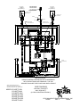
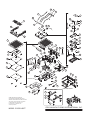
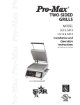
®
®
SPLIT LID TABLE TOP TWO
SIDED GRILL
MODEL
CG14SPT, CG14STE, CG14SPTI, CG14SPTIG
GR14SPTA, GR14SPTC, GR14STE
GR14SPTK, GR14SPTI, GR14SPTIP
®
Installation and
Operation
Instructions
®
2M-Z5818 Rev. N 6/10/2010
GR14SPT
SAFETY SYMBOL
These symbols are intended to alert the user to the presence of
important operating and maintenance instructions in the manual accompanying the appliance.
RETAIN THIS MANUAL FOR FUTURE REFERENCE
NOTICE
Using any part other than genuine Star factory supplied parts relieves the
manufacturer of all liability.
Star reserves the right to change specifications and product design without
notice. Such revisions do not entitle the buyer to corresponding changes,
improvements, additions or replacements for previously purchased
equipment.
Due to periodic changes in designs, methods, procedures, policies and
regulations, the specifications contained in this sheet are subject to change
without notice. While Star Manufacturing exercises good faith efforts to provide
information that is accurate, we are not responsible for errors or omissions
in information provided or conclusions reached as a result of using the
specifications. By using the information provided, the user assumes all risks in
connection with such use.
MAINTENANCE AND REPAIRS
Contact your local authorized service agent for service or required maintenance. Please record
the model number, serial number, voltage and purchase date in the area below and have it ready when you call to ensure
a faster service.
Model No.
Authorized Service Agent
Reference the listing provided with the unit
Serial No.
Voltage
Purchase Date
or
for an updated listing go to:
Website:
E-mail Telephone:
www.star-mfg.com
[email protected]
(800) 807-9054 Local (314) 781-2777
Service Help Desk
Business
Hours:
8:00 am to 4:30 p.m. Central Standard Time
Telephone:
(800) 807-9054 Local (314) 781-2777
Fax:
(800) 396-2677 Local (314) 781-2714
E-mail
[email protected]
[email protected]
[email protected]
Website:
www.star-mfg.com
Mailing Address: Star International Holdings Inc., Company
10 Sunnen Drive
St. Louis, MO 63143
U.S.A
2
GENERAL SPECIFICATIONS
B
D
C
IL1378
A
FIRST OPEN POSITION
Model No
FULL OPEN POSITION
(A) Width (B) Depth
(C) Closed Inches (D) Open Inches
Grill Surface Inches Inches
Voltage Wattage
(cm)
(cm)
(cm)
(cm)
CG14SPT-120C
CG14SPT-120V
Aluminum
CG14SPT-230V
CG14SPT-240V
CG14SPTI-240
CG14SPTI-ARB
Iron
CG14SPTID240
CG14SPTIG240
CG14SPTK-120
CG14SPTK120C
CG14SPTK240
CG14STKE-120
Aluminum
GR14SPTA-120
GR14SPTA120C
16”
GR14SPTA-240
(40.6)
GR14SPTA-CE
GR14SPTC-120
Chrome
GR14SPTC-240
GR14SPTI-240
Iron
GR14SPTIP240
GR14SPTK-120
GR14SPTK120C
GR14SPTK-240
GR14STE-120
Aluminum
GR14STE-120V
GR14STKE-120
GR14SPTG-240
GR14SPTG-120
23 1/8”
(58.7)
14 1/4” (36.3)
14 1/4” (36.3)
14 1/4” (36.3)
14 1/4” (36.3)
17 1/4” (43.8)
17 1/4” (43.8)
17 1/4” (43.8)
17 1/4” (43.8)
14 1/4” (36.3)
14 1/4” (36.3)
14 1/4” (36.3)
14 1/4” (36.3)
14 1/4” (36.3)
14 1/4” (36.3)
14 1/4” (36.3)
14 1/4” (36.3)
17 1/4” (43.8)
17 1/4” (43.8)
17 1/4” (43.8)
17 1/4” (43.8)
14 1/4” (36.3)
14 1/4” (36.3)
14 1/4” (36.3)
14 1/4” (36.3)
14 1/4” (36.3)
14 1/4” (36.3)
14 1/4” (36.3)
14 1/4” (36.3)
31 5/8” (80.3)
31 5/8” (80.3)
31 5/8” (80.3)
31 5/8” (80.3)
34 5/8” (87.9)
34 5/8” (87.9)
34 5/8” (87.9)
34 5/8” (87.9)
31 5/8” (80.3)
31 5/8” (80.3)
31 5/8” (80.3)
31 5/8” (80.3)
31 5/8” (80.3)
31 5/8” (80.3)
31 5/8” (80.3)
31 5/8” (80.3)
34 5/8” (87.9)
34 5/8” (87.9)
34 5/8” (87.9)
34 5/8” (87.9)
31 5/8” (80.3)
31 5/8” (80.3)
31 5/8” (80.3)
31 5/8” (80.3)
31 5/8” (80.3)
31 5/8” (80.3)
31 5/8” (80.3)
31 5/8” (80.3)
120
120
230
240
240
240
240
240
120
120
240
120
120
120
240
230
120
240
240
240
120
120
240
120
120
120
240
120
2,300
2,300
2,112
2,300
3,550
3,550
3,550
3,550
2,300
2,300
2,300
2,300
2,300
2,300
2,300
2,110
2,300
2,300
3,550
3,220
2,300
2,300
2,300
2,300
2,300
2,300
2,300
2,300
Approximate Weight
Amps NEMA Plug Shipping
lbs. (kg)
19.2
19.2
9.2
9.6
14.8
14.8
14.8
14.8
19.2
19.2
9.6
19.2
19.2
19.2
9.6
9.2
19.2
9.6
14.8
14.8
19.2
19.2
9.6
19.2
19.2
19.2
9.6
19.2
Installed
lbs. (kg)
5-30P
5-20P
IEC 320
6-15P
6-20P
6-20P
6-20P
6-20P
5-20P
5-30P
6-15P
5-20P
5-20P
5-30P
81 (37.8) 68 (30.9)
6-15P
IEC 320
5-20P
6-15P
6-20P
6-20P
5-20P
5-30P
6-15P
5-20P
5-20P
5-20P
6-15P
5-20P
GENERAL INSTALLATION DATA
CAUTION
This equipment is designed and sold for commercial use only by personnel trained and experienced
in its operation and is not sold for consumer use in and around the home nor for use directly by the
general public in food service locations.
Before using your new equipment, read and understand all the instructions & labels associated with
the unit prior to putting it into operation. Make sure all people associated with its use understand the
units operation & safety before they use the unit.
All shipping containers should be checked for freight damage both visible and concealed. This
unit has been tested and carefully packaged to insure delivery of your unit in perfect condition. If
equipment is received in damaged condition, either apparent or concealed, a claim must be made
with the delivering carrier.
Concealed damage or loss - if damage or loss is not apparent until after equipment is unpacked, a
request for inspection of concealed damage must be made with carrier within 15 days. Be certain to
retain all contents plus external and internal packaging materials for inspection. The carrier will make
an inspection and will supply necessary claim forms.
INSTALLATION
1. This two sided grill is equipped for the voltage shown on the nameplate. It will operate on alternating
current only, however the specified voltage must be applied.
2.120 volt units must be plugged into a dedicated 120 VAC line with a 20 Amp receptacle.
230-240 volt units do not require a dedicated 240 VAC circuit with a 15 Amp receptacle.
DO NOT CONNECT THE UNIT TO ANY TYPE OF VOLTAGE OTHER THAN THAT ON THE
NAMEPLATE. DOING SO WILL DAMAGE THE UNIT AND VOID THE WARRANTY.
WARNING
INITIAL START UP
Level unit using the adjustable feet under the unit (approximately 1/2" adjustment).
Before using the unit for the first time, wipe down the exterior and toasting area with a damp cloth.
Take to a well ventilated area and heat for approximately 30 minutes. The grill may emit a small
amount of smoke as the cooking surfaces reach 450°F (232°C). Do not be alarmed, as the smoke is
caused by oils associated with the manufacturing process and will stop when the burn off is complete.
Brush off any debris from the toasting surface.
SEASONING THE COOKING SURFACES (NON CHROME SURFACES)
FIRST TIME SEASONING
Follow your company/corporate guidelines for seasoning cooking surfaces. or
1. Bring the grill to 300°F (149°C) and leave it on while doing the next two steps.
2. Brush the cooking surfaces with a SALT-FREE release agent.
If using an aerosol agent, first apply into a cup and then brush onto cooking surface.
3. Let sit for 20 minutes, and then wipe clean using a warm damp cloth.
DAILY SEASONING
The grill should not require much seasoning while in use. In most cases, brush a light coating of a
SALT-FREE baking release agent in the morning and occasionally throughout the day will be enough
to prevent any sticking. It is not necessary to brush before grilling each item.
PRESET TIME AND TEMPERATURE
If adjustments are required, please refer to the time or temperature programming section in this
manual.
°F/°C CONVERSION
To change the temperature display from °F to °C or from °C to °F, hold the TEMP button while the
unit is turned off. While holding the TEMP button, turn the unit on. The display will be the changed
temperature mode. To change back, repeat the procedure.
OPERATING INSTRUCTIONS
1. Turn unit on by placing switch in "ON" position. The "Heat On" indicator, program number and
display will flash indicating unit is heating. When the preset temperature is reached, the heating
light, display and program light indicator will stop flashing followed by 3 beeps. (Initial startup
heating time is approximately 30 minutes).
2. Place product on the bottom cooking surface of the unit and close the lids.
3. Press program button and let displayed time count down to "0" at which time unit will beep.
To turn off the beeper, press program button again.
4. Raise lids until it engages into first indent and remove food. Using spatula, scrape residue into
grease catcher tray.
Note: Metal utensils with rounded corners may be used, however, using nonmetal utensils will
prolong the life of the cooking surface.
5. Turn the unit off when not in use.
TEMPERATURE/TIMER CONTROLLER OPERATION SPECIFICATIONS
Startup:
1. The preset time will flash until preset temperature is reached.
2. When the control reaches preset temperature, time display, "Heat On" indicator and program
indicator will stop flashing and the alarm will beep three times.
Temperature:
1. To view the actual temperature, press and hold "Temp Button." Display will read "Lo F" if temperature
is below 273°F (134°C) and "Hi F" if temperature is above 573°F (301°C).
To Program Time and Temperature:
1. Press and hold "TEMP" (actual temperature displays).
2. While holding "TEMP," press and hold any program button on the Left one second, the LED
above the program number light and the display reads "_ _ _ _." Enter the four-digit security code
sequence, 4, 3, 2, 1. The security code will not show on the display. Once the correct sequence
has been entered, the preset time will be displayed and the LED for that program will begin to
flash.
3. Set the time with the "+ or -" buttons.
4. Press the "TEMP" button to save the time.
5. The preset temperature will now be displayed.
6. Set the desired temperature for this program using the "+ or -" buttons.
7. Press the "TEMP" button to save temperature and to exit programming mode for this program.
The LED will stop flashing but will remain lit.
8. Press any other program button within 15 seconds to continue programming without re-entering
the security code.
9. While programming a program (LED is flashing), if no input is received for 15 seconds, the unit
will revert to normal operation and the security code must be re-entered.
Note: Temperature settings are done with the left side buttons only. The time settings
programmed on the Left buttons will also be programmed onto the right side. See below to make
time changes to the right side only. Each programming change must be saved by pressing the
"TEMP" button!
Right Side (Timer only):
1. To Change the time on the right side, press and hold the "TEMP" button, and press and hold any
program button on the right for one second. The LED above the program button will light and
the Right Display will read "_ _ _ _." Enter the four-digit security code sequence, 4, 3, 2, 1. The
security code will not show on the display. Once the correct sequence has been entered, the
preset time will be displayed and the LED for that program will begin to flash.
2. Set the time with the "+ or -" buttons.
3. Press the "TEMP" button to save the time.
4. The LED will stop flashing but will remain lit.
5. Press any other program button within 15 seconds to continue programming without re-entering
the security code.
6. While programming a program (LED is flashing), if no input is received for 15 seconds, the unit
will revert to normal operation and the security code must be re-entered.
Operation:
1. Pressing any program button (1-4) will start the timer countdown and display the preset time
remaining. The LED for the appropriate program will be lit during countdown and remain lit until
another program is selected.
2. When the display reaches "00:00", the buzzer will sound and the digits will flash.
3. Press the program button to silence the buzzer and return the readout to programmed time.
4. The right and left sides will operate independently of each other. Both timers can be in operation
at the same time. The "00:00" display will show which side is timed out.
MONTHLY INSPECTION
Check all bolts/screws and tighten if necessary.
CLEANING (NON-CHROME SURFACES)
Begin cleaning procedure by using the operating procedures within your organization, or follow the
steps below:
1. If particles adhere to the cooking surface during the day, scrape them off with a spatula.
NOTE: It is best not to let food residue onto the grill, as food build-up on the grill will increase sticking
and smoking. In addition, carbon may build up on the grill surface and reduce the cooking efficiency.
CARBON BUILDUP: A black matter that forms on or near the cooking surface. Generally this is a
combination of: releasing agents, oils, food particles etc. that has cooked itself to the surface. After a
period of time without cleaning, this will reduce performance and material may start flaking off. When
that happens, follow the "Carbon Cleaning" procedures.
2. At the end of the day, wipe down all surfaces with a warm, damp cloth and mild detergent, then
dry.
CARBON CLEANING
When carbon build up occurs, use a carbon removal agent (safe for aluminum & chrome surfaces)
according to the instructions provided with the cleaner. When this process is complete, you must reseason the grill according to your company/corporate guidelines, or the seasoning instructions in this
manual.
DO NOT IMMERSE OR LET THE UNIT STAND IN WATER. DO NOT HOSE DOWN THE UNIT.
KEEP THE UNIT AWAY FROM RUNNING WATER.
CAUTION DO NOT SPLASH THE CONTROL HOUSING! DO NOT SPLASH THE CONDUIT
CONNECTING THE TOP AND BOTTOM OF THE GRILL!
DO NOT USE ICE ON COOKING SURFACE!
WARNING
BEFORE CLEANING ALL OTHER UNITS MAKE SURE POWER IS TURNED OFF AND UNIT
IS UNPLUGGED.
To remove burned on grease or food residue use the following mixture:
1 Tablespoon liquid dish detergent
1 Cup of warm water
While holding top lid with one hand, apply this mixture to cold or warm top cooking surface with a
sponge or plastic scrubbing pad. Wipe with clean sponge or towel until it is clean.
Empty and clean grease catcher tray as required using detergent and water after removing tray from
unit.
CLEANING (CHROME SURFACES)
It takes very little time and effort to keep this Industrial Chromium griddle surface sparkling clean and
performing at top efficiency. DO NOT allow grease to accumulate as it will carbonize and become
difficult to remove. To prevent this condition the following cleaning suggestions should be followed:
1. Remove excess grease and food regularly with a 4” (100mm) wide Razor Sharp type scraper with
rounded corners and wipe surface with a damp cloth if desired.
2. Following the scraping, for end of the day cleaning, a damp cloth and a non-silicated, non-abrasive,
non-chlorinated cleaner such as Bon-Ami may be used to wipe surface clean, followed by wiping
with a clean wet cloth.
3. Use a clean cloth and good non-abrasive cleaner to clean the (NON COOKING SURFACES)
stainless steel body of the griddle. Wipe the control panel front with a soft cloth.
4. At least once a day, remove the waste drawer and wash in the same way as an ordinary cooking
utensil. The drawer is removed by pulling forward and out.
1. Never use pumice, griddle stones, or abrasives on a chromium surface.
2. Never strike a chromium griddle surface with a sharp instrument or spatula edge.
CAUTION
3. Never use steel wool.
4. Never use commercial liquid grill cleaner on the griddle surface.
5. Abusing surface voids the warranty.
CHROME SURFACE LIMITED WARRANTY EXCLUSIONS
CAUTION
Your Chrome Two Sided Grill has been designed to give you many years of cooking reliability and
requires minimum maintenance to keep the chrome surface in its original condition. All Chrome
surfaces are warranted for a period of 1 years against manufacturing defects to the original owner
from the date of installation. This limited warranty is void if it is determined by Star Manufacturing
International Incorporated or one of its authorized representatives that the chrome surface has been
misused or abused or subjected to the following situations:
1. Improperly installed.
2. Incorrect voltage applied to electric Pro-Max units allowing the surface to overheat and discolor.
3. The misuse of any instrument or tool which scratches or makes indentations in the surface which
could cause the surface to peel, flake, or chip off.
4. The use of any chemical or abrasive cleaning solution, griddle brick, stone, screen or other cleaning
products which could damage and affect the performance of the chrome surface.
5. The neglect of daily routine maintenance to the chromium surface.
Visit our Website at: www.star-mfg.com
Email: [email protected]
THOROUGHLY INSPECT YOUR UNIT ON ARRIVAL
This unit has been tested for proper operation before leaving our plant to insure delivery of your unit in perfect condition. However, there are instances in
which the unit may be damaged in transit. In the event you discover any type of damage to your product upon receipt, you must immediately contact the
transportation company who delivered the item to you and initiate your claim with same. If this procedure is not followed, it may affect the warranty
status of the unit.
LIMITED EQUIPMENT WARRANTY
All workmanship and material in Star products have a one (1) year limited warranty on parts & labor in the United States and Canada. Such warranty is
limited to the original purchaser only and shall be effective from the date the equipment is placed in service. Star's obligation under this warranty is limited
to the repair of defects without charge, by the factory authorized service agency or one of its sub-agencies. Models that are considered portable (see below)
should be taken to the closest Star service agency, transportation prepaid.
> Star will not assume any responsibility for loss of revenue.
> On all shipments outside the United States and Canada, see International Warranty.
* The warranty period for the JetStar six (6) ounce & Super JetStar eight (8) ounce series popcorn machines is two (2) years.
* The warranty period for the Chrome-Max Griddles is five (5) years on the griddle surface. See detailed warranty provided with unit.
* The warranty period for Teflon/Dura-Tec coatings is one year under normal use and reasonable care. This warranty does not apply if damage occurs to
Teflon/Dura-Tec coatings from improper cleaning, maintenance, use of metallic utensils, or abrasive cleaners. This warranty does not apply to the
“non-stick” properties of such materials.
> This warranty does not apply to "Special Products" but to regular catalog items only. Star's warranty on "Special Products" is six (6) months on parts
and ninety (90) days on labor.
> This warranty does not apply to any item that is disassembled or tampered with for any purpose other than repair by a Star Authorized Service Center or
the Service Center's sub-agency.
> This warranty does not apply if damage occurs from improper installation, misuse, wrong voltage, wrong gas or operated contrary to the Installation and
Operating instructions.
> This warranty is not valid on Conveyor Ovens unless a "start-up/check-out" has been performed by a Factory Authorized Technician.
PARTS WARRANTY
Parts that are sold to repair out of warranty equipment are warranted for ninety (90) days. The part only is warranted. Labor to replace the part is
chargeable to the customer.
SERVICES NOT COVERED BY WARRANTY
1.
2.
3.
4.
5.
6.
7.
8.
9.
Travel time and mileage rendered beyond the 50 mile radius limit
Mileage and travel time on portable equipment (see below)
Labor to replace such items that can be replaced easily during a daily cleaning
routine, ie; removable kettles on fryers, knobs, grease drawers on griddles, etc.
Installation of equipment
Damages due to improper installation
Damages from abuse or misuse
Operated contrary to the Operating and Installation Instructions
Cleaning of equipment
Seasoning of griddle plates
10.
11.
12.
13.
14.
15.
16.
17.
18.
Voltage conversions
Gas conversions
Pilot light adjustment
Miscellaneous adjustments
Thermostat calibration and by-pass adjustment
Resetting of circuit breakers or safety controls or reset buttons
Replacement of bulbs
Replacement of fuses
Repair of damage created during transit, delivery, &
installation OR created by acts of God
PORTABLE EQUIPMENT
Star will not honor service bills that include travel time and mileage charges for servicing any products considered "Portable" including items listed below.
These products should be taken to the Service Agency for repair:
ALL:
* The Model 510FD Fryer.
* Pop-Up Toasters
* The Model J4R, 4 oz. Popcorn Machine.
* Butter Dispensers
* The Model 518CMA & 526CMA Cheese Melter.
* Pretzel Merchandisers
* The Model 12MC & 15MC & 18MCP Hot Food Merchandisers.
* Pastry Display Cabinets
* The Model 12NCPW & 15NCPW Nacho Chip/Popcorn Warmer.
* Nacho Chip Merchandisers
* All Hot Dog Equipment except Roller Grills & Drawer Bun Warmers.
* Accessories of any kind
* All Nacho Cheese Warmers except Model 11WLA Series Nacho Cheese Warmer.
*SneezeGuards
* All Condiment Dispensers except the Model HPDE, & SPDE Series Dispenser.
* Pizza Ovens
* All Specialty Food Warmers except Model 130R, 11RW Series, and 11WSA Series.
* Heat Lamps
* All QCS/RCS Series Toasters except Model QCS3 & RCS3 Series.
* Pumps
The foregoing warranty is in lieu of any and all other warranties expressed or implied and constitutes the entire warranty.
FOR ASSISTANCE
Should you need any assistance regarding the Operation or Maintenance of any Star equipment; write, phone, fax or email our Service Department.
In all correspondence mention the Model number and the Serial number of your unit, and the voltage or type of gas you are using.
Part# 2M-4497-2 05/06 RB
120V UNITS PLUG
TOP ELEMENT
RIGHT
(ELEMENT MAS ALTO)
TOP ELEMENT
LEFT
(ELEMENT MAS ALTO)
NEMA 5-20P 2,300 WATT
NEMA 5-30P 2,300 WATT
240V UNITS PLUG
NEMA 6-15P 2,300 WATTS
NEMA 6-20P 3,550 WATTS
SENSOR - RIGHT
(SENSORIO)
SENSOR - LEFT
(SENSORIO)
GREEN
WHITE
BLACK
TRANSFORMER
(TRANSFORMADOR)
TERMINAL BLOCK
(BLOQUE TERMINAL)
RELAY
(RELE)
8
7
8
7
B A
D C
14
2
1
10
9
15
3
6 2
4
4
5
8 4
1
0
6 2
0
8 4
1
16
12
11
6
13
12
11
10
9
BOTTOM ELEMENT
(ELEMENTO MAS BAJO)
SWITCH
(INTERRUPTOR)
5
13
6
15
E3 E4
E11
E1
E12
E2
3
14
1
2
16
E7 E6 E5
REAR OF CONTROLLER
FOR REFERENCE
WIRING DIAGRAM IS SHOWN AS UNIT IS ASSEMBLED
WITH THE BOTTOM PLATE REMOVED. THE TOP
DESCRIPTIONS ARE THEIR POSITIONS WHEN UPRIGHT.
SOME ITEMS ARE INCLUDED FOR
ILLUSTRATIVE PURPOSES ONLY AND IN
CERTAIN INSTANCES MAY NOT BE AVAILABLE
MODEL CG14SPT-120V
CG14SPT-240V
CG14SPTI-240V
GR14SPTA-120V
GR14SPTA-240V
GR14SPTK-120C
GR14SPTI-240V
WIRE DIAGRAM
120V/240V, 2300 WATT
240V, 3550 WATT
(2J-Z6323 CONTROLLER ONLY)
STAR MANUFACTURING INTERNATIONAL, INC.
SK2078
REV. A
12/28/06
TOP ELEMENT
RIGHT
(ELEMENT MAS ALTO)
TOP ELEMENT
LEFT
(ELEMENT MAS ALTO)
SENSOR - RIGHT
(SENSORIO)
BS 1363A PLUG
(13 AMP)
SENSOR - LEFT
(SENSORIO)
GREEN / YELLOW
STRIPE
INLET IEC 320 16A
BLUE
BROWN
TRANSFORMER
(TRANSFORMADOR)
G
TERMINAL BLOCK
(BLOQUE TERMINAL)
8
20
N
L
RELAY
(RELE)
7
8
12
14
2
1
10
9
15
3
6 2
5
8 4
1
0
6
13
16
4
4
B A
D C
19
12
11
11
6 2
0
8 4
1
18
7
10
9
230V UNITS
BOTTOM ELEMENT
(ELEMENTO MAS BAJO)
SWITCH
(INTERRUPTOR)
5
13
6
15
E3 E4
E11 E1
E12
3
14
16
1
2
E2
E7 E6 E5
REAR OF CONTROLLER
FOR REFERENCE
WIRING DIAGRAM IS SHOWN AS UNIT IS ASSEMBLED
WITH THE BOTTOM PLATE REMOVED. THE TOP DESCRIPTIONS ARE THEIR POSITIONS WHEN UPRIGHT.
SOME ITEMS ARE INCLUDED FOR
ILLUSTRATIVE PURPOSES ONLY AND IN
CERTAIN INSTANCES MAY NOT BE AVAILABLE
WIRE DIAGRAM, 230V, 2300 WATT
(2J-Z6323 CONTROLLER ONLY)
MODEL: GR14SPTA-UK-230V, 2300 WATT
STAR MANUFACTURING INTERNATIONAL INC.
THIS DRAWING CONTAINS INFORMATION CONFIDENTIAL TO STAR MFG. INT'L. INC.
NO REPRODUCTION OR DISCLOSURE OF ITS CONTENTS IS PERMITTED.
SK2017
10
Rev A
08/10/2004
120V UNITS PLUG
NEMA 5-20P 2,300 WATTS
NEMA 5-30P 2,300 WATTS
TOP ELEMENT
RIGHT
(ELEMENT MAS ALTO)
TOP ELEMENT
LEFT
(ELEMENT MAS ALTO)
240V UNITS PLUG
NEMA 6-15P 2,300 WATTS
NEMA 6-20P 3,550 WATTS
SENSOR - RIGHT
(SENSORIO)
SENSOR - LEFT
(SENSORIO)
GREEN
WHITE
BLACK
TERMINAL BLOCK
(BLOQUE TERMINAL)
TRANSFORMER
(TRANSFORMADOR)
RELAY
(RELE)
8
7
8
7
17
6 2
4
0
5
14
B A
D C
16
8
1
6 2
8 4
1
0
4
6
13
4
2
15
3
1
17
BOTTOM ELEMENT
(ELEMENTO MAS BAJO)
SWITCH
(INTERRUPTOR)
5
13
6
15
E3 E4
E11
E1
E12
E2
3
14
1
16
2
E7 E6 E5
REAR OF CONTROLLER
FOR REFERENCE
WIRING DIAGRAM IS SHOWN AS UNIT IS ASSEMBLED
WITH THE BOTTOM PLATE REMOVED. THE TOP
DESCRIPTIONS ARE THEIR POSITIONS WHEN UPRIGHT.
WIRE DIAGRAM
SOME ITEMS ARE INCLUDED FOR
ILLUSTRATIVE PURPOSES ONLY AND IN
CERTAIN INSTANCES MAY NOT BE AVAILABLE
STAR MANUFACTURING INTERNATIONAL, INC.
MODEL: GR14SPTIP240
SK2336
11
REV. -
12/7/07
18
19
20
17
1
20
2
3
52
4
16
53
24
21
22
5
3
6
11
7
54
8
55
9
10
25
31
26
27
28
56
57
33
58
36
37
35
23
57
29
14
22
30
11
12
13
34
69
15
32
39
9
40
46
59
41
42
38
45
65
70
60
44
43
33
66
48
NAMEPLATE
67
50
68
51
47
49
4“ LEGS ONLY
64
GR14SPTIP240
63
62
SOME ITEMS ARE INCLUDED FOR
ILLUSTRATIVE PURPOSES ONLY AND IN
CERTAIN INSTANCES MAY NOT BE AVAILABLE
61
This drawing contains information confidential
to Star Manufacturing International, Inc.
No reproduction or disclosure of its
contents is permitted.
MODEL CG/GR14SPT
48
STAR MANUFACTURING INTERNATIONAL, INC.
SK1901
12
REV. F
4/27/2010
PARTS LIST
June 10, 2010, Rev N
CG14SPT, CG14SPTIG-120V, 120C, 230V & 240V, CG/GR14STE
GR14SPTA, GR14SPTC, GR14SPTK-120V, 120C, 230V & 240V
MODEL CG/GR14SPTI-240V, GR14SPTIP240 Split Lid Table Top Grill
Item
Part No
Qty
No
1
2M-Z2620
2
2
2C-Z3200
4
3
2A-Z3827
2
D9-GR0181
2
4
D9-Z11716
1
D9-Z11717
5
2C-Z5883
8
6
B9-04-WB-0046 2
7
D9-GR0182
2
8
D9-Z2133
2
2A-Z6604
9
12
2A-Z9514
D9-Z3902
10
2
D9-Z9513
PS-Z9325
2
11
PS-Z9326
PS-Z9521
2
12
2C-Z3350
2
13
D9-Z3903
2
14
2E-Z3278
2
PS-GR0356
PS-GR0355
PS-GR0504
15
2
2F-Z9651
2F-Z8349
2F-Z7967
16
2V-Z3152
2
2B-Z3336
2B-Z9515
4
2B-Z10355
17
2B-Z12554
2
2B-Z12555
18
19
20
21
22
23
24
25
26
27
2C-08-07-0040
2C-08-07-0262
2C-Z2992
2C-Z3917
2E-Z2898
2E-Z3768
2C-Z3780
2V-Z3252
2A-Y6142
2C-1516
12
8
12
4
2
2
4
2
4
4
Description
LABEL CAUTION, BI-LINGUAL
PIN - TOP HOUSING
PLATE, STAMPING CONDUIT
TOP HOUSING & CONDUIT ASSEMBLY
TOP HOUSING, LT SPLT
TOP HOUSING, RT SPLT
10-24 X 1/2” FZA SCREW, TOP HOUSING
CLAMP WIRE SUPPORT
TOP RETAINING PLATE ASSEMBLY
INSULATION FIBERGLASS TOP
SPACER - INSULATION PLATE
PLATE - TOP ELEMENT RETAINING
ELEMENT, HEATING, TOP 500W
ELEMENT, HEATING, TOP 500W 230/240V
ELEMENT, HEATING, TOP 700W
HALF CLAMP - .188 DIAMETER
BRACKET, PROBE MOUNT
RTD PROBE - 48” LONG WIRE - THERMISTOR
KIT, 2F-Z3237 CASTING REPLACMENT
KIT, 2F-Z5615 CASTING REPLACMENT
KIT, 2F-Z5615 COATED CASTING REP.
CASTING - TOP SMOOTH, CHROME
CASTING - TOP SMOOTH, IRON
CASTING - TOP GROOVE, IRON
HANDLE
14” CG14SPT ARM
ARM
ARM
ARM, LEFT ST
ARM, RIGHT ST
ACORN NUT, 1/4-20 ACHD STL NP
WASHER 1/4 INT STL NP
BOLT 1/4-20X1 PHP STL NP
RIVET, POP,
CONDUIT ASSEMBLY
LOCKNUT, CONDUIT 1/2”
RETAINER, CONDUIT
TOP HOUSING LATCH ROD
SLEEVE HANDLE
SCREW 10-24 X 1” STL RH NP, LATCH ROD
Application
CG14STKE-120, GR14STB, GR14STE,
GR14STKE120C
SPTC, SPTI
SPTC, SPTI
120V
SPT, SPTA, SPTC, SPTA, SPTG 230/240V
SPTI
SMOOTH - ALUM
GROOVED - ALUM
GROOVED - ALUM
SPTC, SPTI
CG14SPTK-120/240V
CG14STKE-120, GR14STB, GR14STE,
GR14STKE120C
CG14STKE-120, GR14STB, GR14STE,
GR14STKE120C
IMPORTANT: WHEN ORDERING, SPECIFY VOLTAGE OR TYPE GAS DESIRED
INCLUDE MODEL AND SERIAL NUMBER
Some items are included for illustrative purposes only and in certain instances may not be available.
Star Manufacturing International, Inc.
13
PAGE
1
OF4
PARTS LIST
June 10, 2010, Rev N
CG14SPT, CG14SPTIG-120V, 120C, 230V & 240V
GR14SPTA, GR14SPTC, GR14SPTK-120V, 120C, 230V & 240V
MODEL CG/GR14SPTI-240V, GR14SPTIP240 Split Lid Table Top Grill
Item
No
28
29
30
31
32
33
Part No
2R-Z3345
2C-Z2593
D9-Z11677
D9-Z3826
2A-Z6484
D9-GR0152
D9-GR0393
D9-GR0394
D9-GR0507
D9-GR0461
Qty
1
4
1
1
2
1
2M-Z5817
34
35
36
37
38
39
40
41
42
43
44
45
46
47
48
49
50
2M-Z3337
2M-Z10851
2M-Z11984
2M-Z11983
Z1-70-07-0343
2M-12-07-0038
2I-05-07-0013
D9-GR0518
D9-GR0517
2E-Z3808
2J-Z6323
D9-GR0387
D9-GR0380
2K-Z1971
D9-GR0151
D9-GR0382
2E-Z3335
2E-05-07-0350
2E-05-07-0351
2E-Z2894
D9-GR0156
D9-Z3259
D9-Z10086
2A-Z11500
2A-Z11501
D9-GR0150
D9-GR0034
2K-Y6764
Description
Application
COUNTER BALANCE - SPLIT TOP
SCREW - 10-24X1 1/2 SL HX/W NP
INSULATION BAFFLE ASSEMBLY
INSULATION - BAFFLE
PLATE (COUNTER BALANCE MOUNT)
BODY ASSEMBLY
CG14SPTK-120/240V
GR14SPTIP
GR14STE
GR14STB
CG14SPT, CG14SPTI, GR14SPTA, GR14SPTC,
GR14SPTI, GR14SPB,. GR14STE
GR14SPT-120/240V & CUL
CG14SPTK-120/240V
GR14STE-120
GR14STE-120V
BODY ASSY - 14” CG/CG14
BODY ASSY 14” SPT
OVERLAY-STANDARD
1
OVERLAY
1
1
1
SWITCH GUARD
LABEL ON & OFF
BOOT SWITCH
1
GREASE DRAWER ASSEMBLY
1
1
1
SWITCH TOGGLE
TIME/TEMPERATURE CONTROL
CONTROL PROGRAMMING
CONTROL PROGRAMMING
SPACER
FACEPLATE ASSEMBLY
FACEPLATE ASSEMBLY
RELAY DOUBLE POLE-SINGLE THROW
TRANSFORMER 230V/10V 6VA
TRANSFORMER 115/10V 6VA
TERMINAL BLOCK (304)
REAR PLATE ASSEMBLY
1
BASE BOTTOM
4
4” NON SKID FOOT BASE
FOOT 1” SOLID RUBBER
1
GREASE CABINET ASSEMBLY
1
BUSHING 90 SR 17-2
1
14
1
2
1
CG14SPTK
GR14SPTKG120
CG14SPTK-120/120C/240V
GR14SPTK-120/120C, GR14SPTKM120
CG14SPTK
230V
CG14SPTID240, GR14SPTA-CE
SPTC, SPTI
CG14SPTK, GR14SPTG
CG14SPTID240
GR14SPTA-CE
IMPORTANT: WHEN ORDERING, SPECIFY VOLTAGE OR TYPE GAS DESIRED
INCLUDE MODEL AND SERIAL NUMBER
Some items are included for illustrative purposes only and in certain instances may not be available.
Star Manufacturing International, Inc.
14
PAGE
OF
2
4
PARTS LIST
June 10, 2010, Rev N
CG14SPT, CG14SPTIG-120V, 120C, 230V & 240V
GR14SPTA, GR14SPTC, GR14SPTK-120V, 120C, 230V & 240V
MODEL CG/GR14SPTI-240V, GR14SPTIP240 Split Lid Table Top Grill
Item
No
51
52
53
Part No
Qty
2E-Z4119
D9-GR0193
D9-GR0194
2E-Y9251
2E-Z2905
D9-GR0189
D9-GR0177
D9-GR0501
CORD POWER
CORD POWER
1
2
1
D9-GR0335
D9-GR0176
54
55
56
57
58
59
60
61
62
63
64
65
66
67
68
69
D9-GR0500
D9-GR0334
PS-GR0361
PS-GR0362
PS-GR0503
2F-Z9653
PS-GR0363
PS-GR0364
2N-Z9324
2N-Z9327
2N-Z9520
2N-Z11709
2C-08-07-0285
D9-Z2618
D9-Z9701
D9-Z2888
D9-Z2619
2V-Z3027
D9-Z9516
2C-08-07-0262
2C-Z2992
2T-6447
2M-Z11301
2R-Z4621
D9-Z11304
PS-GR134
Description
CORD POWER
CORD SET CONT EUR 16AMP
CORD POWER
TOP BURN GUARD ASSEMBLY
BURN GUARD ASSEMBLY - LEFT
BURN GUARD, LT WELD ASSY
BURN GUARD ASSEMBLY - RIGHT
1
1
1
2
12
1
1
1
2
2
4
4
1
1
1
1
AR
BURN GUARD, RT WELD ASSY
KIT, 2F-Z1945, CASTING SM REPLACMENT
KIT, 2F-Z1947, CASTING GR REPLACMENT
KIT, 2F-Z1947, COATED CASTING GR REPL
CASTING - SMOOTH BOTTOM, CHROME
KIT, 2F-Z1949, CSTNG - BOTTOM, IRON
KIT, 2F-Z1951, CSTNG - GROOVE, IRON
ELEMENT, HEATING, BTM
ELEMENT, HEATING, BTM 1300 W
ELEMENT, HEATING, BTM 2150 W
ELEMENT, 650 WATT, 120V
SCREW 10-24 x 3/4 x 3/8
BOTTOM ELEMENT RETAINING PLATE
BOTTOM ELEMENT RETAINING PLATE
INSULATION - 14”
BOTTOM INSULATION RETAINING PLATE
CROSS SUPPORT
SUPPORT BRACKET, LEGS
WASHER 1/4 INT STL NP
BOLT 1/4-20X1 PHP STL NP
THERMOSTAT 118V-236V
LABEL - DIAL
KNOB, 1-3/4 - .250”D”HOLE
PLATE, COVER
KIT, BEARING ASSY, COUNTER BALANCE
Application
120V
120C
240V
CG14SPT-230V between 1-15-01 thru 8-16-04
CG14SPT-230V
SPTI- 240V
CG14STKE-120, GR14STB, GR14STE,
GR14STKE120C
CG14SPTI-230
CG14STKE-120, GR14STB, GR14STE,
GR14STKE120C
CG14SPTI-230
GR SERIES (NON-SPTI)
CG SERIES (NON-SPTI)
CG SERIES (NON-SPTI)
SPTC
GR14SPTI
CG14SPTI
120V
230V-240V (NON-SPTI)
SPTI 230/240V
CG14STKE, GR14STE, GR14STKE
SPTC
SPTC, SPTI
SPTC, SPTI
SPTC, SPTI
SPTC, SPTI
SPTIP
SPTIP
SPTIP
SPTIP
3
IMPORTANT: WHEN ORDERING, SPECIFY VOLTAGE OR TYPE GAS DESIRED
PAGE
4
INCLUDE MODEL AND SERIAL NUMBER
OF
Some items
are included for illustrative
only and in certain
instances
may not be available.
purposes
Star Manufacturing International, Inc.
15
PARTS LIST
June 10, 2010, Rev N
CG14SPT, CG14SPTIG-120V, 120C, 230V & 240V
GR14SPTA, GR14SPTC, GR14SPTK-120V, 120C, 230V & 240V
MODEL CG/GR14SPTI-240V, GR14SPTIP240 Split Lid Table Top Grill
Item
No
70
NI
Part No
D9-GR0520
Qty
1
Description
Application
CG14SPT, CG14SPTI, CG14SPTIG, GR14SPTA,
GR14SPTC, GR14SPTI, GR14SPTIP, GR14STB,
GR14SPTE
BASE ASSY / GREASE CABINET
D9-GR0522
CG14SPTK, CG14STKE, GR14SPTK,
GR14SPTKM120, GR14STKE
D9-Z11977
CG142TB, CG14B, CG14E, CG14IB, CG14IGTB,
CG14ITB, CG14ITGTB, CG14ITLB, CG14ITSC,
CG14TB, GR14B, GR14E, GR14E, GR14IB, GR14ITB,
GR14SNB, GR14TB, CG14STKE, GR14STB,
GR14STE, GR14STKE
1
PLATE, BASE CONDUIT
IMPORTANT: WHEN ORDERING, SPECIFY VOLTAGE OR TYPE GAS DESIRED
INCLUDE MODEL AND SERIAL NUMBER
Some items are included for illustrative purposes only and in certain instances may not be available.
Star Manufacturing International, Inc.
16
PAGE
OF
4
4