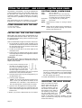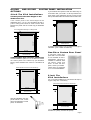
1
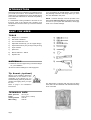
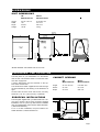
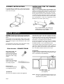
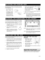
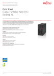
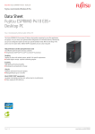
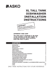
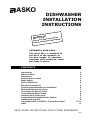
ASKO
DISHWASHER
INSTALLATION
INSTRUCTIONS
NT! tructions
A
T
R
O
P
IM
ins
asher.
f these
w
ll o
the dish
Read a
g
n
i
l
l
a
t
ins
before
AUTOMATIC HIGH LOOP
The drain hose is fastened to
the back of the machine at
the best height. To eliminate
potential drain problems, leave
this hose in place.
CONTENTS
Introduction
What You Need
Dimensions
Preparing the Location
Water Supply
Drain Connections
Electrical Connections
Preparing the Dishwasher for Installation
Moving the Machine into Place
Connecting the Electric Cable
Connecting the Water Supply
Adjusting the Leveling Legs
Fastening the Dishwasher to the Cabinet
Installing the Toe Kick
Fitting the D3250 and D3530 Custom Door Panel
Index
2
2
3
3
4
5
6
6
7
8
8
8
9
9
10-11
12
SAVE THESE INSTRUCTIONS FOR FUTURE REFERENCE
Page 1
INTRODUCTION
Read these instructions carefully and completely before
you install the machine. The installation should be
carried out by a qualified person who is familiar with all
local codes and ordinances for electrical and plumbing
connections.
If a dishwasher is being installed in this area for the
first time, most of the cabinet work, plumbing, and
electrical has to be done before you move the machine
into place.
If you are replacing an old dishwasher, you must check
the plumbing connection and wiring before you move
the new dishwasher into place.
NOTE: Cosmetic damage must be reported to the
ASKO dealer within five days from the date of purchase.
As soon as you unpack the dishwasher, thoroughly
check it for cosmetic damage.
WHAT YOU NEED
TOOLS
1)
Phillips No. 2 screwdriver
2)
Flat blade screwdriver
3)
Torx screwdriver size T 20
4)
Adjustable wrenches (if you use copper fittings)
5)
Open-ended wrench (1/2" [12 mm] or 5/8" [16 mm])
6)
Tape measure
7)
Spirit level
8)
Electric drill with 1” drill bit
9)
Keyhole saw
MATERIALS
♦ Minimum 3/8" OD copper tubing of sufficient length
for your installation
♦
Shut-off valve and fittings for water supply line
Tip Guards (optional)
When it is not possible to attach the
dishwasher to the cabinet or the
underside of the cabinet top, you
should install tip guards to prevent the
machine from tipping when you open
the door.
Tip Guards
(P/N 8070851)
Refer to page 4 for installation
instructions.
TECHNICAL DATA
Water pressure
Power
Heating element
Max loading
Page 2
18-176 psi
120 V, 60 Hz, 15 amp.
1200 W
1300 W
The dishwasher is shipped with the high loop drain
hose, inlet hose and electrical cord attached and ready
to be connected.
DIMENSIONS
UNIT DIMENSIONS
Height
Width
Depth
Weight
US
Measurements
Metric
Measurements
32-1/4"–35-1/2"
*24"
23-5/8"
106 lb
819–902 mm
610 mm
600 mm
48 kg
46-5/8"
1184 mm
24"
610 mm
6-1/4" - 8-1/4"
159 - 210 mm
32-1/4 to 35-1/2"
819 to 902 mm
23-5/8"
600 mm
Door
6-1/4"
159 mm
2"
50 mm
2-1/4"
57 mm
*Models D3250FI and D3530FI are 23-5/8” wide.
PREPARING THE LOCATION
The best place for your dishwasher is in the kitchen
near the sink. This makes it easier to connect the water
and drain supply lines.
A built-in dishwasher must be enclosed on the top,
both sides and the back.
The electrical and water supplies should enter through
the area indicated by the shading on the illustration at
right.
CABINET OPENING
Height
Width*
Depth
US
Measurements
Metric
Measurements
32-1/4"–35-1/2"
24-1/8”"
23-7/16"
819–902 mm
613 mm
596 mm
Access holes must be round and smooth, and they
should be 1-1/2” to 2” (38 to 50 mm) in diameter.
2"
50 mm
6-1/4" to 8-1/4"
159 to 210 mm
23
59 -7/
6 16
m "
m
For a 6” toe kick installation, the part numbers are:
White=8073567-0; Black=8073567-86.
32-1/4 to 35-1/2" minimum
819 to 902 mm
EUROPEAN INSTALLATIONS
The kick plate supplied with your dishwasher fits a 24"
(610 mm) opening. When using European standard
installation, a 23-1/2” (597 mm) wide toe kick is available
from your ASKO dealer. (Part numbers: White=80735660; Black=8073566-86.)
24-1/8
613 mm
Page 3
CORNER INSTALLATION
If the dishwasher is installed in a corner, there must be
a minimum clearance of 2” (50 mm) from the side wall
so the door can open.
INSTALLING THE TIP GUARDS
(OPTIONAL)
When it is not possible to fasten the dishwasher to the
cabinet, you should install tip guards to prevent the
machine from tipping when the door is opened. The tip
guards can be attached either to the floor or the wall.
The tip guards should be mounted behind the machine,
19” (483 mm) apart (measuring center to center) and
18-1/2” (470 mm) from the front of the machine. (Note:
This measurement could vary, depending on the
thickness of the custom panel, if any.)
Rear
Tip Guards
(P/N 8070851)
2” clearance
We recommend that you install tip
guards when it isn’t possible to fasten
the dishwasher to the cabinet.
WATER SUPPLY
WARNING! Plumbing connections must comply with
applicable sanitary, safety and plumbing codes in your
area.
The machine can be connected to either a hot or cold
water supply. If a cold water supply is used, the washing
times will be longer but the performance will not be
affected.
The dishwasher comes with a 6-foot PEX water supply
line that has a 3/8" NPT female connection.
E ASY I NSTALL CONNECTIONS
PEX tubing with 3/8”
compression fitting
PEX tubing has a 95-year
spec life. Fits American
dishwasher water supply
valves.
After determining where the water supply line will enter
under the sink, drill a 1-1/2" to 2” (38 mm to 50 mm)
access hole and run the line to the approximate inlet
valve location shown in the figure below. The water line
inlet valve is on the right rear of the machine.
For service convenience, a shut-off valve (not supplied)
should be installed in the supply line in an easily
accessible location, such as, beneath the sink.
It is important that the water supply line and the shut-off
valve have a sufficient flow volume. At last 3 gallons (12
liters) per minute must be able to pass through the
line. The water pressure should be 18-176 psi.
WARNING!
In order to prevent heat damage to the inlet valve, all
solder connections must be made before the water
line is connected to the dishwasher.
Drain hose boot
Ready to be cut to desired
drain connection. Only
one clamp required.
Electrical cord
110-120 volts, 15/20 amp
cord supplied with unit.
WARNING!
(1) Water supply
(2) Water supply valve
(not supplied)
Do not use an extension cord for this appliance.
NOTE: Be sure to run the PEX tubing through the hole
to sink compartment before moving the
dishwasher into position.
Page 4
DRAIN CONNECTIONS
ASKO provides a 7/8” (22 mm) corregated drain hose
which is connected to the back of the unit to form a high
loop. If additional drain hose is needed, please
purchase an additional ASKO drain hose and joint it to
the provided hose with a 7/8” (22 mm) copper tube.
NOTE: Do not use any fittings anywhere in the drain
line that are less than 7/8" (22 mm) ID.
THREE WAYS TO INSTALL
DRAIN CONNECTIONS
A.) Typical connection to sink plumbing before
trap (high loop drain)
The access hole for the drain line should be 1-1/2" (38 mm).
The end of the drain line is 1/2” (12 mm), but it is
adjustable to 7/8”, 3/4”, 5/8” (22mm, 19 mm, and 16
mm). If the drain connection is larger than
1/2” (12 mm), you can
easily cut the drain line to
fit the connection.
The illustrations to the right show three ways to connect
the drain supply line.
THE HIGH LOOP
The high loop is necessary for proper
draining. Therefore, all ASKO
dishwashers have the drain hoses
attached to the drain pump and
fastened to the top back of the unit,
as illustrated. This gives the drain hose an automatic
high loop, which is necessary for proper draining. The
drain hose is fastened at the best high loop height.
B.) Connection to air gap then to the trap
To eliminate potential drain problems, simply leave
this hose in place.
IMPORTANT THINGS TO
REMEMBER:
♦ Failure to provide the proper drain connection height
(minimum of 20" (508 mm) above the bottom of the
dishwasher base) or a 20" (508 mm) high loop will
result in improper drainage, which will damage the
machine.
C.) Connection to waste disposer with air gap
♦ No part of the drain hose should be higher than 35"
(889 mm) from the bottom of the dishwasher.
♦ The drain hose can be extended to a maximum length
of 10 feet (3048 mm). Joints and jointed tubes, if any,
must have a minimum 7/8" (22 mm) ID.
♦ If the drain line is going to be connected to a waste
disposer, be sure to remove the knockout or plug
from the fitting on the disposer before connecting
the drain line.
♦ Do not use fittings smaller than 7/8” (22 mm);
otherwise the water may not drain properly.
NOTE:
When the installation is ready, open the supply valve
and let the pressure act for a while. Then check that all
connections are tight and there are no leaks.
Don’t forget to remove the knockout
or plug from the disposer fitting.
Page 5
ELECTRICAL CONNECTIONS
WARNING!
Before working on wiring for any
electrical appliance, be sure the electrical power
has been turned off at the breaker/fuse box.
WARNING!
Do not use an extension cord for this appliance.
WARNING!
Disconnect
electrical
power
supply and place a tag at the disconnect switch
indicating that you are working on the circuit.
WARNING!
Electrical
and
grounding
connections must comply with the applicable
portions of the national electrical code and/or
other local electrical codes.
The dishwasher comes with an electrical
cord for 110-120 volts, 15/20 amp supplied.
This cord should be plugged into the 110120 volt outlet under the sink.
If the cord is not long enough, or if a hard-wire
installation is needed, follow instructions on page 8.
NOTE:
Access holes should be 1-1/2” to 2” (38 mm
to 50 mm) in diameter with no sharp edges.
GROUNDING INSTRUCTIONS
This unit must be grounded to operate properly. It must
be connected to a grounded metal, permanent wiring
system, or an equipment-grounding conductor must
be run with the circuit conductors and connected to the
equipment-grounding terminal or lead of the appliance.
Damage to the dishwasher could occur if it is not
properly grounded.
WARNING! Make sure the water supply line,
drain line and branch circuit wiring do not touch
any exposed terminals of dishwasher wiring.
PREPARING THE DISHWASHER FOR INSTALLATION
At this point the styrofoam, plastic wrap, and the wood
pallet (base) should be removed from the dishwasher.
Now is an excellent time to inspect for any shipping
damage. Should you find any damage, you should
report it to your dealer or builder immediately.
Be sure to remove the toe kick and toe kick insulation
which are wrapped in heavy brown paper and packed
inside or on top of the dishwasher.
THE FILL STRIPS
All standard ASKO dishwashers (Models D3120, D3250,
D3350, D3530) have color-coded fill strips to finish off
the installation. To prevent damage to the machine, be
sure to remove the shipping screws that secure the
fill strips to the access panel. These screws are to be
thrown away. Do not replace them into the access
panel.
SLIDES FOR LEGS
The unit comes with white plastic slides for the legs to
protect the kitchen floor from being damaged when you
slide the unit into place. The slides simply snap onto
the bottom of the legs.
WARNING!
Do not screw the fill
strips back to the
lower access panel;
otherwise, the
machine will have to
be uninstalled if
service is necessary.
Protective slides for legs
simply snap onto the bottom
of the legs.
Fill Strip
Lower Access Panel
NOTE: If the cabinet opening is European measure-
ment (23-1/2 inches [597 mm]), remove the ll
strips to fit the dishwasher into the opening.
Page 6
MOVING THE MACHINE INTO PLACE
WARNING!
Make sure you put the protective slides on the legs to
prevent damaging the floor when you slide the unit
into place (see page 6).
1.
Position the machine in front of the cabinet
opening.
2.
Make the height adjustment while the dishwasher
is in front of the opening.
3.
Pull out the drain hose to ensure there are no sharp
bends.
4.
Start to feed water and drain lines and electric cord
(if necessary) into the access hole in the cabinet.
5.
Gently slide the unit into the dishwasher opening.
As you do this, feed the drain line and inlet hose
into the access hole in the side of the cabinet.
As you slide the unit into place, feed the drain line and
inlet hose into the access hole in the side of the cabinet.
WARNING! Be careful of sharp edges.
Page 7
CONNECTING THE ELECTRIC CABLE
If the cord is not long enough, or if a hard-wire
installation is needed, follow the steps below to
complete the electrical connection.
WARNING! Before starting this procedure, be sure
the power is turned off at the breaker/fuse box.
1.
Connect supply cable with
a UL-listed strain relief
bushing (if nonmetallic
cable is to be used).
2.
Connect branch circuit
white lead to N lead on filter.
3.
Connect branch circuit
black lead to L lead on filter.
4.
Connect ground wire to ground connection screw
on the bottom.
NOTE: When doing a hard-wire installation, you must
remove the supplied power cord.
CONNECTING THE WATER SUPPLY
In order to prevent heat damage to the inlet valve, all
solder connections must be made before the water
supply line is connected.
Flush the water supply line prior to connecting it to the
water fill tube.
The unit has a float switch in the base pan to protect
against flooding. If the inlet valve connection is not
seated properly, water may leak into the base pan and
activate the float switch.
It is important that the water supply line and the shut-off
valve have a sufficient flow volume. At last 3 gallons (12
liters) per minute must be able to pass through the
line. The water pressure should be 18-176 psi.
(1) Water supply
(2) Water supply valve
(not supplied)
NOTE:
Be sure to run the PEX tubing through the hole
to sink compartment before moving the
dishwasher into position.
TESTING FOR LEAKS
1. Turn on the water supply and check for leaks.
2. Turn the power on at breaker/fuse box and test the
dishwasher operation by running a Rinse cycle.
(This should take about four minutes.)
3. Turn off the electrical power and check for leaks
Page 8
under the dishwasher and sink.
4. Make sure that no kinks have developed in the drain
lines.
If there are no leaks and the dishwasher seems to be
working properly, continue with the installation.
ADJUSTING THE LEVELING LEGS
Now that all the connections are made and the machine
is in place under the cabinet, you should make the final
height adjustment.
1. You should set the
rear foot first. To do
this,
use
a
screwdriver to rotate
the adjusting screw
on the bottom front of
the machine. Turn the
screw clockwise to
raise the foot and
anticlockwise to lower it.
2. Using a 1/2” (12 mm) wrench, adjust the locking
nuts until the machine is
level. (The machine may
have an inclination of 2°
maximum without affecting
its performance.)
3. When the feet are properly adjusted, tighten the
locking nuts to the base pan.
NOTE: When adjusting the unit lower than 33-1/4” (845
mm), the holes on the toe kick will need to be
elongated. An accessory toe kick is also
available for this type of installation. Contact
your dealer to order.
FASTENING THE DISHWASHER TO THE CABINET
It’s necessary to fasten the dishwasher to the cabinet
so it won’t tilt when the door is opened or if something
heavy is placed on the door. Use only the stainless
steel screws provided with the machine.
1.
Use option A for U.S. or European standard
installations. Use option B only for European
standard installations.
2.
Cover the screw heads with the
plastic plugs provided with the
machine.
3.
When the machine is properly
attached, check that the feet are
tight against the floor and that the
machine is level.
NOTE: Option A can be used for U.S. or European
Mounting
Screws
installations. Use option B for European
standard installations only.
NOTE: When it is not possible to attach the dishwasher
to the cabinet, you should install tip guards.
(See “Tip Guards” on page 2.)
INSTALLING THE TOE KICK
Once you have the toe kick bracket in place, you can
install the toe kick, as follows:
SETTING THE TOE KICK
DEPTH
1.
If you have not done so, take the toe kick and felt
insulation from the top of the machine-packaging.
1.
2.
Lay the insulation on the back side of the toe kick to
make sure it fits properly.
Press the grey catches
toward each other to
release the bracket.
2.
3.
Peel the adhesive protection strip off the insulation
and press it firmly to the back side of the toe kick,
making sure you don’t cover any slots on the toe
kick.
Pull out the holders as
far as required.
3.
Press in the catches so
that they lock the
brackets in place.
2.
Hang the kick-plate onto the holders by inserting it
into the grooves.
4.
Positioning the notches on the toe kick at the edge
of the access panel, slide the toe kick up behind
the access panel then let it slide to the floor.
5.
Screw the toe kick to the toe kick brackets.
6.
Adjust the toe kick depth.
ADJUSTING THE TOE KICK
HEIGHT ON D3250FI AND D3530FI
These models come with a European kickplate.
Page 9
FITTING THE D3250FI
AND D3530FI
The D3250FI and D3530FI can only be installed with
a fully-integrated custom door panel that extends from
the toe kick to the counter top. The unit comes with
everything needed to make installing the door panel
easy. The door is predrilled for the panel’s mounting
screws.
The custom panel can be a minimum of 1/4” (6 mm)
thickness to a maximum of 3/4” (19 mm) thickness.
ITEMS PROVIDED WITH THE UNIT
♦ Two 3/8” screws
♦ Four 1-3/4” screws
CUSTOM DOOR PANEL
CUSTOM PANEL DIMENSIONS
Width:
Height:
Thickness:
Weight:
23-1/2” (597 mm)
28-1/8”–30-1/8” (714 mm–765 mm)
(Measured from the top of the panel to
the lower edge of the kitchen cabinet.)
1/4” (6 mm) to 3/4” (19 mm) max
Up to 22 lb.
NOTE: Specifications subject to change without
notice.
NOTE: Heavy-duty door springs can be purchased for
wooden door panels weighing over twelve
pounds. (P/N 8071323-77).
INSTALLING THE CUSTOM PANEL
Before fitting the custom panel, the dishwasher must
be installed underneath the cabinet. After you’ve made
the required measurements, pull the machine out again
to install the panel.
Refer to the illustration at right for instruction references.
1. Fit the handle (A) onto the panel according to the
manufacturer’s instructions. (NOTE: A handle should
be used rather than a knob, because a knob does
not provide enough grip.)
2. Loosen the screws (D) on the outer edges of the
dishwasher door.
3. Pull the turbo fan exhaust frame (E) down until the
lower edge aligns with the lower edge of the cabinets
and tighten the screws.
WARNING!
The custom panel must not obstruct the turbo fan
exhaust. See step 4 above for instructions on how to
adjust the fan exhaust.
4. The two short screws (B) go into
the back of the panel, 16-3/16”
(411 mm) from the upper edge of
the panel and 5/8” (16 mm) from
the outer edges. Insert the short
screws into the panel, leaving 1/8” (3 mm) of space
between the screw head and the panel.
5. Hook the panel screws (F) into the keyholes (C) on
the dishwasher door.
6. Push the panel sidewards.
NOTE: The custom panel should not extend more
than 2-15/16” (75 mm) below the bottom of the
dishwasher door. Otherwise, it will strike the toe
kick and damage the machine and/or the panel.
7. Open the door and tighten the screws (F) inside.
8. Remove the backing from the protective tape and
affix it on the bottom edge of the panel, in front of the
exhaust vent.
9. Before you push the dishwasher into the cabinet
Page 10
opening, test the door to make sure it opens properly.
The door is counter-balanced, so it should remain
in any position. If it doesn’t, you may need to adjust
the door springs (see above).
10. Fasten the diswasher to the cabinet (see page 9).
ADJUSTING THE DOOR SPRINGS
After you install the custom
panel, make sure the door
stays in place at any angle. If
it tends to fall down, pull out
the machine and tension the
door springs on the sides of
the machine by moving them
one hole farther back or by
twisting the spring to make it
shorter. If that doesn’t resolve the problem, you may
need to purchase the heavy-duty door springs (part
number 8071323-77).
D3250FI
AND D3530FI
OPTIONS
CUSTOM PANEL INSTALLATION
4-inch Toe Kick Installations
Custom panels the same height as the
dishwasher door
If the custom panel is the same height as the
dishwasher door, a 2” (51 mm) decorative fill strip or
pull-out cutting board must be used to fill the area
between the panel and the counter top (as illustrated
below).
If you install the door panel to reach the cabinet top, we
recommend that you install a 2” fill strip between the
upper edge of the dishwasher and the counter to hide
the top of the dishwasher and further reduce water noise.
2-inch fill strip
28-1/2"
724 mm
2-inch decorative fill strip or cutting board
4-inch toe kick
A stainless steel fill strip is also available for this type of
installation (part number 8073869-95).
23-1/2"
597 mm
One-Piece Custom Door Panel
4-inch toe kick
Custom panels that extend to cabinet top
Another installation option for a 4” toe kick is to extend
the custom panel to the cabinet top (as illustrated
below), which eliminates the need for a decorative fill
strip.
Panel extends from toe kick to cabinet top
A one-piece custom door
panel with a curved handle
is now available for the FI
dishwashers. This door is
available in stainless steel
(as shown), black, and
white. To order this door
panel, contact your dealer.
These doors are designed
for 4” toe kick installations.
30-1/16"
764 mm
6-inch Toe
Kick Installations
For 6” toe kick installations, the decorative fill strips or
support strips are unnecessary.
Panel extends from toe kick to cabinet top
23-1/2"
597 mm
28-1/2"
724 mm
4-inch toe kick
With this installation, the door
panel extends 1-3/4” inches
above the dishwasher control
panel, as illustrated.
23-1/2"
597 mm
6-inch toe kick
The part number for the 6-inch toe kicks are:
8073567-01 (white), 8073567-86 (black)
Page 11
INDEX
A
Access holes
S
3
C
Cabinet, fastening unit to
Cabinet opening dimensions
Connecting to water supply
Corner installation
Cosmetic damage
9
3
9
4
2
3
11
10
4
E
Electrical cable connection
Electrical connections
European installations
6
T
D
Dimensions, unit
Door panels, fully-integrated
Door springs, adjusting
Drain connections
Slides for rear legs
8
7
3
Technical data
Tip guards
installing 4
Toe kick
installation options on FI units
installing
Tools
2
2
11
9
2
U
Unit dimensions
3
W
Water connection
Water flow volume
Water pressure
9
4
2
F
Fastening unit to cabinet
Fill strips
Fully-integrated door panels
9
6
10
G
Grounding instructions
6
H
Heating element
High loop
Hot water supply
2
5
4
L
Leaks, testing for
Leveling legs, adjusting
8
9
M
Materials
Moving unit into place
2
7
P
Panels, fully-integrated
Placing the unit
Power
Page 12
11
7
2
Art. No 80 758 35 Rev. 02