1
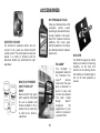
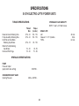
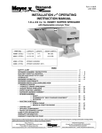
SNOWPLOWS
by Meyer
Out-Front-Electric Hydraulics
Owner’s Manual
Diamond Snowplows
Table of Contents
Page
Introduction . . . . . . . . . . . . . . . . . . . . . . . . . . . . . . . . . . 2
Tripedge Series
Get to Know Your Diamond MDII Snowplow . . . . . 3-6
Get to Know Your Diamond Snowplow . . . . . . . . . . 7-8
Blade Specifications . . . . . . . . . . . . . . . . . . . . . . . 9-10
Controls & Operating Instructions . . . . . . . . . . . . 11-12
Diamond MDII Snow Plow Instructions . . . . . . . . . .13-16
Snowplow Operation . . . . . . . . . . . . . . . . . . . . . . . . . . 17
Removing & Attaching Snowplow . . . . . . . . . . . . . . . . 17
General Maintenance & Adjustments . . . . . . . . . . . 18-19
Troubleshooting . . . . . . . . . . . . . . . . . . . . . . . . . . . 20-22
Efficient Snow Clearance . . . . . . . . . . . . . . . . . . . . . . . 23
Keep Snow Under Control . . . . . . . . . . . . . . . . . . . . . . 23
Selecting Equipment . . . . . . . . . . . . . . . . . . . . . . . . . . 24
Hourly Snow Clearing Capacities . . . . . . . . . . . . . . . . 24
Plow with the Storm . . . . . . . . . . . . . . . . . . . . . . . . . . . 25
Establishing Snow Clearance Plans . . . . . . . . . . . . . . 26
Snowplowing Tips from the Pros . . . . . . . . . . . . . . 27-29
Minerals and Chemicals for Ice Control . . . . . . . . . . . 30
Ice Control Spreaders . . . . . . . . . . . . . . . . . . . . . . . 31-32
Fast Moving Parts List . . . . . . . . . . . . . . . . . . . . . . 33-34
Accessories . . . . . . . . . . . . . . . . . . . . . . . . . . . . . . 35-36
Specifications . . . . . . . . . . . . . . . . . . . . . . . . . . . . . 37-38
Warranty Card . . . . . . . . . . . . . . . . . . . . . . . . Back Cover
Introduction
Snow, despite the beauty it may impart to a bleak winter
landscape, poses the dual threat of inconvenience and danger.
The environmental conditions associated with snow, not to
mention the health hazards and economic loss it may impose,
seriously endanger thousands of lives annually. Business and
industry suffer, and millions of snowbelt residents may be
affected by a single snowstorm.
accessories, and it is so stated in vehicle manufacturer
specifications for snowplow application.
WARNING: Deployment of an air bag while using a Diamond
snowplow will not be covered under Diamond Equipment
warranty.
We also recommend that, for optimum performance, vehicles
used for snowplowing be equipped with:
Diamond Equipment has published this manual to help you get
maximum performance from your Diamond Snowplow and
familiarize you with the features designed for efficiency and
safety; be sure you recognize and understand them. Follow
recommended operation and maintenance instructions, so
when the storm hits, your Diamond Snowplow will be ready and
you will know how to plow like a pro. Do not equip any vehicle
with a snowplow without consulting manufacturer's
recommendations.
•
•
•
•
•
•
•
•
•
Vehicles with Diamond Snowplows installed may be so
equipped as to meet vehicle manufacturers' specifications and
recommended options for snowplowing use. Most vehicle
manufacturers insist that vehicles which are to be used for
snowplowing be equipped with certain options and
Four-Wheel Drive
Minimum 60 Amp Alternator or larger
Minimum 70 Amp Battery or larger (550 C.C.A.)
Mud and Snow Tires
Increased Radiator Cooling
Automatic Transmission
Transmission Cooler
Power Brakes
Power Steering
Under the continuing Diamond Product Improvement Plan,
Diamond Equipment reserves the right to change design details
and construction without prior notice and without incurring any
obligation.
Diamond snowplow equipment should only be used on vehicles equipped with the manufacturer’s snowplow preparation packages. Snowplowing without the original
snowplow preparation package may damage your vehicle and the added weight of the equipment may impair the operation and control of the vehicle. Snowplowing with a
vehicle that the manufacturer does not recommend for that purpose may void your new vehicle warranty. If your vehicle is not originally equipped with the snowplow
preparation package, additional equipment may be necessary before snowplowing. Owners of these vehicles should consult their truck dealer before purchase or
installation of equipment. CAUTION: The installation, on any vehicle, of these parts is not a full substitute for the original equipment snowplow preparation package.
2
Get to know your Diamond MDII® Snow Plow
1. Blade
Steel or Polyethylene sheet is bump and corrosion resistant. Built
to last.
9. MDII® Lift Frame
Allows for fast, complete removal of front end hardware, snow plow
lights and hydraulic unit in one complete module.
2. Adjustable Tripedge Extension Springs
Tripedge gives way when objects are struck at ground level.
Note: Trip Spring tension should be checked on a regular basis
during the snowplowing season. See page 18 under
SNOWPLOW Paragraph 4 for more information.
10. Attaching Pins
Pull 4 blue pins to remove complete assembly or pull 2 yellow pins to
remove moldboard assembly.
11. Lift Arm
Dual Chain locks in position to lift snow plow.
WARNING: LIFT ARM EXTENDS BEYOND BUMPER OF VEHICLE.
TO MINIMIZE DAMAGE FROM A FRONT END COLLISION, LIFT
ARM SHOULD BE REMOVED FROM VEHICLE WHEN SNOW PLOW
IS REMOVED.
3. Power Angling Cylinders (1-1/2" x 10")
Hydraulically positions the moldboard straight, or to right or left.
4. Cutting Edge (Optional)
Replaceable, high carbon steel provides extra long operating life.
Recommended for commercial plowers.
12. Diamond Snow Plow Lights
Complies with the Federal Motor Vehicle Safety Standards.
5. Wear Shoes
Wear Shoes are an integral part of the Tripedge to reduce wear.
13. Electric Hydraulic Power Unit (E-60H, E-57H)
Operates snow plow hydraulically- raises, lowers, angles, holds and
floats moldboard in plowing position.
6. Pushframe
Designed to attach the snow plow to the vehicle, to pivot blade
for angle plowing, and to hold plow at proper distance in front of
vehicle.
14. Sno-Flo® Powder Coat
Baked on finish that looks like glass, provides an extremely hard, low
friction surface that outlasts ordinary paint by a large margin.
7. Upper/Lower Pivot Pins
Pins that attach blade to pushframe.
15. Crankstand
Positions Moldboard and Lift Frame for easy attaching and detaching.
8. Clevis Frame
Allow snow plow assembly to be attached or detached from
vehicle in minutes.
16. Hydraulic Cover
Protects the Hydraulic Unit from the elements and also enhances the
appearance of your vehicle.
3
4
CRANKSTAND STORAGE
To store Crankstand on the Lift Frame slide the tube that is attached
to the side of the Crankstand over the receiver tube on the driver's
side of the Lift Frame. Insert the chain locking pin through the vertical
holes on both the tubes. Note: Crankstand should always be fully
retracted (up) and be pinned in the vertical transport position
when not In use. Receiver Tube Cap may be placed over the driver
side transport tube while the Crankstand is in use on the A-Frame.
The Receiver Tube Cap may also be switched over to the Adjustment
Tube of the A-Frame when the Crankstand is mounted to the Lift
Frame.
ATTACHING MOLDBOARD ASSEMBLY ONLY
Attach A-Frame to Lift Frame by connecting Crankstand to the
adjustment tube in the center of the A-Frame Frame. Insert the
chained locking pin all the way through the vertical holes on both the
tubes. Crank up A-Frame until the holes on the back ears of the AFrame are about 12” off the ground. Pull out the Yellow Handle Pins
on both sides of the Lift Frame. Twist handle slightly to the right or
left disengaging the pin. Pull truck up to the A-Frame / Moldboard
assembly aligning the A-Frame ears between the two lift frame plates
until contact is made with the Clevis Frame. Once you feel contact,
push the moldboard assembly a few inches forward, this insures
proper alignment so that the A-Frame is square to the Clevis Frame.
Adjust the Crankstand up until the front of the truck raises slightly.
Rotate the Yellow Handled Pins so that the small leg realigns with the
slot, engaging the pin. The spring loaded pin should snap into place
locking the A-Frame to the lift frame. Note: If pins do not properly
engage move the truck slightly forward a few more inches and/or
adjust (raise or lower) the Crankstand until pins lock into place. If
only one pin should engage, retract the stand to the full upright
position. Remove the Crankstand from the A-frame by removing the
chained locking pin. Reattach the Crankstand to the transport tube
on the driver's side of the Lift Frame in the vertical transport position.
Attach the Lift Chain to the Lift Arm through the two hooks on the lift
arm. Adjust the lift chain at the lift arm so that there are 2-3 links of
slack. This ensures that the plow blade will lift fully and be able to
follow the ground contour while plowing. Raise the plow with the
hydraulics and swing the moldboard slightly left or right until the pin
engages.
Storage of the Crankstand is the responsibility of the operator.
The stand can be stored on the lift frame in the retracted
position to the driver's side transport tube or inside the vehicle
cab.
HYDRAULIC COVER
Install Black Hydraulic Cover before installing the Lift Assembly to
the Lift Frame. Begin by sliding the Hydraulic Cover down over the
Lift Ram. Slide the side covering the motor carefully over the motor,
do not force or stretch the Hydraulic Cover; it will fit comfortably over
all parts of the Hydraulic Unit. Feed the three coil wires (red, green
and black) through the hole located on backside of cover. Route
coupler weather plugs through holes in cover where power angling
hoses enter. Snap Cover together. Caution: Care should be taken
with the installation and or removal of the Hydraulic Cover, including
partial removal when repairs are performed on the Hydraulic Lift Unit.
Tearing of the Hydraulic Cover for any reason will not be covered
under the Diamond Warranty.
5
DETACHING THE COMPLETE ASSEMBLY
Leave control switch in lower float position and push down on the
Lift Arm. Disconnect the electrical plug and slip on weather caps
over both ends. Attach Crankstand to the adjustment tube in the
center of the A Frame using the chained locking pin. Caution:
Crankstand must be secured at all times. Adjust the Crankstand
down until the bottom of stand touches the ground. Pull and twist the
two rear Blue Handle Pins to disengage. Next pull and twist the two
front Blue Handle Pins to disengage. If the pins do not pull easily,
adjust stand up or down slightly to remove tension on the pins until
they disengage. At this time the lift frame should be leaning forward
slightly, at rest on the top of the Crankstand. Pull truck away.
until the front of the truck raises slightly. The rear Blue Handle Pins
should now be aligned with the rear holes on the clevis frame. Twist
all Blue Handle Pins so that the small leg re-aligns with the slot,
engaging the pins. The rear spring loaded pins should snap into
place. Note: If pins do not lock immediately the A-Frame is not
square to the Clevis Frame. Move truck slightly forward and/or adjust
the Crankstand up or down until rear pins engage. Once the back
pins are locked push the top of the Lift Frame towards the truck
locking the front pins to the clevis frame. Remove the Crankstand
from the A-frame by removing the chained locking pin. Reattach the
Crankstand to the transport tube on the driver's side of the Lift
Frame in the vertical, retracted position. Caution: Crankstand must
be secured at all times. Reattach the one step electrical
connection.
DETACHING MOLDBOARD ASSEMBLY ONLY
Leave control switch in lower float position and push down on the
Lift Arm. Disconnect hydraulic couplers and Lift Chain from Lift Arm.
Attach Crankstand to the adjustment tube in the center of the AFrame using the chained locking pin. Caution: Crankstand must be
secured at all times. Adjust the Crankstand down until the bottom
of stand touches the ground. Pull and twist the Yellow Handled Pins
to disengage. If the pins do not pull easily, adjust stand up or down
slightly to remove tension on the pins until they disengage. Pull truck
away.
ATTACHING THE COMPLETE ASSEMBLY
Check that all four Blue Handle Pins are disengaged. Drive the truck
up to the MDII assembly centering the hood of the truck to the lift
arm to assure proper alignment with lift frame guide plates until
contact is made. Once contact is made drive forward, pushing the
assembly a few inches. This insures the A-Frame is square to the
Clevis Frame for proper pin attachment. Adjust the Crankstand up
6
Get to know your Diamond Tripedge Snowplow
1. Blade
High strength steel. Built to last.
8. Pushframe
Designed to attach snowplow to vehicle, to pivot blade for angle
plowing, and to hold plow at proper distance in front of vehicle.
2. Adjustable Tripedge Extension Springs
Tripedge gives way when objects are struck at ground level.
NOTE: Trip spring tension should be checked on a regular basis
during the snowplowing season. See Page 18 under
SNOWPLOW Paragraph 4 for more information.
9. Upper/Lower Pivot Pins
Pins that attach blade to pushframe.
10. Lift Arm
Dual chain locks in position to lift snowplow. WARNING: Lift arm
extends beyond bumper of vehicle. To minimize damage
from a front-end collision, lift arm should be removed from
vehicle when snowplow is removed.
3. Power Angling Cylinders
Enables the operator to hydraulically position the moldboard
straight, or to right or left, by simply activating the fingertip
control switch.
11. MDII® Mounting System
Allows for fast, complete removal of all front end hardware,
snowplow lights, hydraulic unit, moldboard, sector and
pushframe, in one complete module.
4. MDII Attaching System
Rubber coated stainless steel pins give you the choice of
removing the plow, mount, hydraulics, and lights (blue pins) or to
remove only the plow (yellow pins).
12. Snowplow Lights
Lights and brackets comply with the Federal Motor Vehicle
Safety Standards.
5. Cutting Edge (optional)
Replaceable, high carbon steel provides extra long operating life.
Recommended for commercial plowers.
8. Wear Shoes
Wear shoes are an integral part of the tripedge to reduce wear.
13. Tubular PULL-AWAY™ Mounting System
Allows for fast removal of all snowplow components in two
complete, easy to manage, modules.
7. Electric Hydraulic Power Unit
Operates snowplow hydraulically - raises, lowers, angles, holds
and floats blade in plowing position.
14. Tubular PULL-AWAY™ Easy Hitch™ System
Allows moldboard, sector and pushframe to be detached and
attached as a separate module in minutes.
7
12
MDII® Mounting System
E-57H
10
E-60H
9
11
1
2
8
14
13
5
6
3
4
8
Pull-Away™ Easy Hitch™
Mounting System
TRIPEDGE SERIES
Model 7.5
For 1/2 and 3/4 ton 4x4 Standard Duty
Pickups and Sport Utility Vehicles
STEEL MOLDBOARD SPECIFICATIONS
BLADE WIDTH
BLADE HEIGHT
GAUGE STEEL
VERTICAL RIBS
TYPE OF SPRINGS
NUMBER OF TRIP-EDGE PlNS
CUTTING EDGE (OPTIONAL)
PLOW WIDTH AT FULL ANGLE
PUSHFRAME
PIVOT PIN DIAMETER
POWER ANGLING RAMS
AVERAGE SHIPPING WEIGHT
POLY MAX MOLDBOARD SPECIFICATIONS
7 1/2’
27 5/16’’
12 Gauge
6
Extension (4)
6
2
81’’
3” x 2” x 3/16”
1 3/16”
1 1/2’’ x 10”
600 lbs.
BLADE WIDTH
BLADE HEIGHT
MOLD BOARD SHEET THICKNESS
VERTICAL RIBS
TYPE OF SPRINGS
NUMBER OF TRIP-EDGE PINS
CUTTING EDGE(OPTIONAL)
PLOW WIDTH AT FULL ANGLE
PUSHFRAME
PIVOT PIN DIAMETER
POWER ANGLING RAMS
AVERAGE SHIPPING WEIGHT *
*weight is based on average depending on specific mounting
9
71/2'
29”
3/8" U.H.M.W. Polyethylene
6
Extension (4)
6
2
81"
3” x 2” x 3/16’’
1 3/16’’
1 1/2” x 10”
625 Lbs.
TRIPEDGE SERIES
Models 8.0, 8.5, 9.0
For 3/4 and One Ton 4x4 Standard
Duty Pickups and Cab-Chassis Vehicles
STEEL MOLDBOARD SPECIFICATIONS
BLADE WIDTH
BLADE HEIGHT
GAUGE STEEL
VERTICAL RIBS
TYPE OF SPRINGS
NUMBER OF TRIP-EDGE PINS
CUTTING EDGE (OPTIONAL)
PLOW WIDTH AT FULL ANGLE
PUSHFRAME
PIVOT PIN DIAMETER
POWER ANGLING RAMS
AVERAGE SHIPPING WEIGHT*
8.0'
29 3/8”
11 Gauge
6
Extension (4)
6
2
86”
3" x 2” x 3/16"
1 3/16”
1 1/2" x 10"
800 Lbs.
8.5'
29 3/8”
11 Gauge
6
Extension (4)
6
2
92”
3” x 2” x 3/16”
1 3/16”
1 1/2” x 10”
825 Lbs.
*weight is based on average depending on specific mounting
10
9.0'
29 3/8”
11 Gauge
6
Extension (4)
6
3
97"
3” x 2" x 5/16"
1 3/16”
1 1/2” x 10”
875 Lbs.
HML-10 10’
32”
7 Gauge
7
Extension (6)
DAGT-10 10’
32”
7 Gauge
7
Extension (6)
2” x 12”
2” x 12”
II. Controls and Operating Instructions
Tripedge Series
Special Features
1. Diamond's unique dual pivot pins and diagonal bracing system distribute plow loads better and reduce stress on the
pushframe and cylinders.
2. Diamond's tripedge gives way when objects are struck at ground level. Diamond's rigid moldboard system keeps the blade
upright and plowing until your truck loses traction. Fig. 2.
3. Diamond Snowplows have a more pronounced curve in the blade design which means a better job in throwing snow.
4. Diamond's heavy duty undercarriage support system uniformly distributes snow plowing loads to the vehicle frame.
5. Diamond's unique wear shoes are engineered to load up into the tripedge angle while plowing.
6. Dual chain hooks on the lift arm provide easier hookup and greater stability of the blade.
7. Pivot Pins are 1 3/16" diameter with one-piece construction to eliminate welded-on washers.
11
TRIP-EDGE
Fig. 2
12
Diamond®
™ Snowplow Instructions
CHOICE 1: Removing MDII (Entire Mount)
13
CHOICE 1: Attaching MDII (Entire Mount)
14
CHOICE 2: Removing MDII (Moldboard Only)
15
CHOICE 2: Attaching MDII (Moldboard Only)
16
Snowplow Operation
Over-the-Road Operation
The snowplow should only be in operation when the vehicle ignition switch
and the Electro-Touch® control switch are in the "ON"
position. Care should be taken to insure that the ElectroTouch® control switch is kept dry and free from moisture
during normal operation.
Based on the experience of our representatives and other background, we
advise a maximum transporting speed of 40 m.p.h. or locally regulated
speeds, which ever is less, dependent upon road conditions. The operators
should, of course, maintain a safe stopping distance and adequate passing
clearance at all times.
When the Electro-Touch® control switch is turned "On,"
yellow lights illuminate the location of the individual touch
pads for the functions of the snowplow: (Up), (Angle Left),
(Angle Right), and (Down).
When transporting the snowplow to avoid engine overheating, angle the
moldboard completely, carrying it as low as permitted for safety by road and
surface conditions.
Lowering of the snowplow an inch at a time is possible by tapping the down
arrow in short intervals. Holding down the down arrow will activate a green
light located in the upper left corner of the Electro-Touch® switch. This
green light indicates the snowplow is now in the Lower/Float position. In this
position the snowplow will be able to follow the contour of the road and the
snowplow can also be angled to the left or right. Touching the up arrow
automatically cancels the Lower/Float position.
Removing Moldboard Assembly
1.
2.
3.
4.
This switch is short circuit and temperature protected. All wire connections
must be securely plugged together. If any of these conditions exist, the red
overload LED will light. The overload LED (red light) is located in the upper left
corner below the float light of the Electro-Touch® switch. Reset is
accomplished by turning off the ignition switch or by turning the power switch
off momentarily and then back on. If an overheating temperature condition
exists, it will be necessary to allow the unit to cool down for approximately 2
minutes. If the overload light is still illuminated after attempts to reset the
switch have failed, contact your nearest authorized Diamond Distributor for
repairs.
Be sure moldboard is on ground! The chain can have a small amount of
tension to help support the back of the pushframe.
Pull hook-up pins in pushframe outward and turn to hold in place.
Lower lift ram all the way and detach chains from lift arm. Reverse the
above procedure to reattach snowplow to vehicle.
WARNING: Lift arm extends beyond bumper of vehicle. To minimize
damage from a front-end collision, lift arm should be removed from
vehicle when snowplow is removed.
ADJUSTING CHAIN FOR PROPER SLACK WHEN PLOWING SNOW
1.
Be sure moldboard is on ground and pushframe is reattached at proper
hole in front mounting frame.
2.
Be sure lift piston is fully retracted.
3.
Hold chains taut and choose the third link above lift arm, place that link
in lift arm locking groove. This procedure will provide the proper amount
of slack when snowplowing for the moldboard to follow the contour of
the ground. You may wish to mark these links with paint or tape for easy
identification. Due to the differences in vehicle ride heights, extra chain
links may vary in length.
Note: On Model E-60 only to regulate the lower speed, locate the lower adj.
screw on page 19, Fig. 0-3. Turn adj. screw in to slow down or out for faster
lower speed. Adjustments must be made with moldboard on the ground.
This feature is not available on model E-57.
CAUTION: When the snowplow is not in operation, the Electro-Touch®
Control Switch should be in the "OFF" position.
17
General Maintenance
SNOWPLOW
NOTE: ALWAYS lower moldboard to ground when vehicle is not in use.
Check the Troubleshooting Chart, pages 20-22, and Post Season
Maintenance, page 19, for advice on maintaining the unit.
1.
Check and maintain hydraulic fluid reservoir level to 1 " - 1 1/2" from top
cap. (Lift cylinder in down position.)
2.
Check entire hydraulic system for leaks. A significant drop in hydraulic
fluid level is evidence of a leak which must be corrected to prevent
serious damage. See page 19
3.
Before and after each season, remove sector pivot pins, thoroughly
grease pivot tubes and reinstall pins. Lubricate all pivot points with
chassis lube.
4.
ADJUSTING TRIP SPRING TENSION - Tighten
adjustment nut to the point when spring coils
begin to separate. Tighten bottom locknut to
hold in place.
5.
WEAR SHOES
A. Inspect moldboard wear shoes for wear
and height adjustment.
B. Always replace wear shoes as soon as they start to wear through.
C. Adjust the wear shoes to maintain cutting edge height of 1/2"
above ground in snowplowing position. (Can be set higher when
used on gravel driveways.
6.
CUTTING EDGE
Replace the cutting edge before it wears to the attaching bolts. This will
prevent permanent damage to the trip edge.
7.
MOUNTING BOLTS
Retighten all mounting bolts after first snowplowing session and at
regular intervals through the season.
8.
SNO-FLO® PAINT
At the beginning and end of each season, remove any accumulated rust,
then paint the moldboard surface with Meyer Sno-Flo® paint to inhibit
rust formation. Touch-up paint is also available in aerosol cans—both
Sno Flo® yellow and black.
Diamond Equipment recommends this maintenance information for regular
service. Sustained heavy operation may call for more frequent service.
Snowplowing subjects a vehicle to exceptionally rugged use. As a result, it is
important to inspect and bring the snowplow and vehicle up to maximum
operating conditions. Inspection should be made of both the vehicle and
snowplow prior to the plowing season and after each use.
Pre-Season Maintenance
Scheduled vehicle maintenance should be performed as recommended by
the manufacturer.
Don't forget that in addition to keeping equipment in order:
1.
Keep windshield wipers, heaters and lights working.
2.
Diamond offers as standard equipment quartz halogen snowplow lights
for even brighter illumination.
3.
Equip vehicles with chains where necessary.
4.
Provide operators with protective clothing and with rubber gloves for
handling snow melting chemicals.
VEHICLE ELECTRICAL SYSTEM—For maximum efficiency, the vehicle
supporting the snowplow must be properly serviced. The system should
consist of at least a 70 amp/hr. battery and a 60 amp alternator. Be sure to
check regularly:
1.
Battery terminals to assure they're clean and free of corrosion.
2.
Electrical connections, to assure they're tight and corrosion-free. Taping
may be called for. All wires must be held clear of moving or hot engine
parts or sharp sheet metal.
3.
Battery must be in top operating condition.
4.
Alternator and regulator, to assure maximum electrical output.
18
NOTE: PROTECTION AGAINST RUST AND CORROSION
When the power unit is not used for extended periods, protect the chromed
lift piston fully extending and coating it with chassis lubricant. Coat the
exposed portions of the power angling cylinder rods with chassis lubricant
to protect against corrosion.
SNOWPLOW STORAGE
1. When snowplow is disconnected, extend lift cylinder to end of
stroke and coat chrome rod with light grease. This fills the cylinder
with hydraulic fluid and protects the interior and exterior from rust
and corrosion.
2. Whenever Moldboard is disconnected, coat the exposed portions of
the power angling cylinder chrome rods with light grease to protect
them from corrosion.
3. Be sure to reconnect quick couplers to keep them clean and prevent
contamination of the system.
4. Coat all pivot pins and other wear points with chassis lubricant.
5. Unplug all electrical connections at power unit. Coat all connections
with a dielectric compound to prevent corrosion and plug into their
corresponding weather plugs. Unplug the snowplow lights, tape or
use a dielectric compound at light connections to prevent corrosion.
6. Remove PULL-AWAY™ lift frame module from vehicle. Liberally
coat insides of frame receiver tubes and ends of lift frame with
chassis grease/anti-seize lubricant. Protect frame receiver tubes
from dirt and other types of contamination by installing the receiver
tube caps when the lift frame is removed from the vehicle
7. WARNING: Lift arm extends beyond bumper of vehicle. To
minimize damage from a front-end collision, lift arm should be
removed from vehicle when snowplow is removed.
Post-Season Summer Maintenance
1.
2.
3.
4.
Draining & Replacing Meyer M-1 Hydraulic Fluid
Drain fluid through drain hole in base, shown in Figure a 0-3, by
completely retracting cylinder lift position and unbolting unit to pour
fluid out, or use a suction pump. Disconnect the fittings at the Power
Angling cylinders, completely retract the cylinder rods and purge
cylinders and hoses of all hydraulic fluid. The complete hydraulic
system should then be flushed out with clean mineral spirits or
hydraulic oil before adding new Meyer M-1 Hydraulic Fluid.
Screen-Type Filters - Clean the filters (all models) with mineral spirits
or equivalent and blow out with compressed air. See Figure 0-3.
Diamond Hydraulic Fluid M-1 is specially formulated with an anti-ice
additive for almost constant viscosity in subzero temperatures.
Because it is free-flowing in extreme cold, the unit's performance and
efficiency are not affected by winter weather. It is effective for a
maximum of one year. Always carry an extra quart of Meyer Hydraulic
Fluid M-1 or equal fluids. Use of any inferior fluids will void the
Diamond warranty.
Refill power unit with Meyer Hydraulic Fluid M-1 by fully retracting lift
piston and filling reservoir to 1 1/2’’ below the filler hole. Fill and bleed
hoses and Power Angling cylinders by loosening hydraulic fittings at
cylinders until they leak. Power angle the plow repeatedly from one
side to the other until fluid flows steadily from the fittings while
maintaining a constant check on the reservoir fluid level. The filling end
of the cylinder should be higher than the piston end to facilitate
removal of air. Raise and lower the plow several times. With lift rod fully
retracted check fluid level and replace filter plug.
Filler Hole and
Relief Valve
Pressure Relief Valve
Grounding Point
“B” Solenoid
(red wire)
“C” Solenoid
(green wire)
“A” Solenoid
(black wire)
Cross-over Relief
Valve
19
E-60H
E-57H
Motor
Right Angle
Lower Adjustment
Angle Left
FIGURE 0-3
TROUBLESHOOTING CHART FOR ELECTRIC HYDRAULIC POWER UNITS
This chart is intended to be used as an aid in diagnosing problems on Diamond Hydraulic Power Units. It is not a substitute for factory training and
experience. Be certain to read the General Information and Testing Tips sections before attempting any troubleshooting. Additional detailed
information as well as all electrical schematics may be found in Service Manuals 1-667 (E-60, E-60H) and E-57H.
GENERAL INFORMATION
Before any troubleshooting is started, make certain the following conditions are met.
1. The moldboard is pointing straight ahead. This can often be done by coupling the hose from the left cylinder into the right cylinder and pushing
the snowplow by hand.
2. The power angling cylinders must be installed correctly. The left cylinder has a hose with a male half of a coupler attached while the right
cylinder only has the female half of a coupler attached. Reverse them if installed on wrong side.
3. The solenoid coils must be on their proper valve. The "C"- coil (green wire) must be located on the valve closest to the power angling hoses.
The "B"-coil (red wire) is positioned on the valve furthest from the power angling hoses. The “A” coil (black wire) is smaller in diameter and is
easily located on the E-60 power unit. On the E-57 power unit, the "A" coil (black wire) is located on the back side of the unit.
4. The electrical installation must have been made according to instructions supplied by Diamond Equipment.
TESTING TIPS
Many tests do not require removing the Power Unit from the vehicle. However, more thorough testing can be done by using the Meyer Test Stand
which allows direct pressure and Amperage readings.
1. Use a screwdriver or other small tool to check for magnetism of solenoid coils “A”, “B” & "C". Place the tool on the nut securing the coil and
have an assistant operate the switch. You should feel strong magnetic attraction.
2. Use a test light or volt meter to determine whether there is power at harness or switches.
3. When determining Ampere draw of motor, always obtain the highest value possible, i.e., at maximum raise or angle with motor running.
4. Proper rotation for motor is indicated by an arrow on the top of the E-57 pump.
5. The pump shaft (all models) of a good pump can be turned smoothly using two fingers. If it can't be turned easily, the pump is too tight and
must be replaced.
6. Pump pressure can be measured at an angle hose (note pressure at full angle) or in the pressure filter port (an adapter is necessary for the filter
port). (See Figure 0-3.)
7. If hydraulic system is contaminated it is recommended that the hydraulic unit, power angling rams and hoses be drained and flushed clean.
The system should then be refilled with Meyer M-1 oil. See pages 18-19.
20
Troubleshooting Chart for Electric Hydraulic Power Units
MODEL
CONDITION
POSSIBLE CAUSE
CORRECTION
All
Power
Angling
Models
Plow does not lift or lifts
slowly- motor operates.
1.
2.
3.
4.
5.
6.
7.
Low hydraulic fluid level
Discharged battery.
Leaking or open “A” cartridge.
No current to “B” coil. (red wire)
Inoperative “B” coil. (red wire)
Malfunctioning motor.
Malfunctioning pump.
1.
2.
3.
4.
5.
6.
7.
Add fluid to proper level.
Recharge battery.
Clean or replace “A” cartridge.
Locate malfunction and repair.
Replace “B” coil. (red wire)
Repair or replace motor.
Replace pump.
All
Power
Angling
Models
Plow does not angle right motor operates.
1.
2.
3.
4.
5.
6.
7.
Improper coupler engagement.
Mechanical bind or interference.
Malfunctioning coupler.
No current to “C” coil. (green wire)
Inoperative “C” coil. (green wire)
Inoperative “C” cartridge.
Leaking or open crossover relief valve.
1.
2.
3.
4.
5.
6.
7.
Engage coupler properly.
Eliminate mechanical bind or interference.
Repair or replace coupler.
Locate malfunction and repair.
Replace “C” coil. (green wire)
Clean or replace “C” cartridge.
Clean or replace crossover relief valve.
All
Power
Angling
Models
Plow does not angle left motor operates.
1.
2.
3.
4.
Improper coupler engagement.
Mechanical bind or interference.
Malfunctioning coupler.
Leaking or open crossover relief valve.
1.
2.
3.
4.
Engage coupler properly.
Eliminate mechanical bind or interference.
Repair or replace coupler.
Clean or replace crossover relief valve.
All
Power
Angling
Models
Plow will not angle Motor operates.
1. Improper coupler engagement.
2. Mechanical bind or interference.
3. Leaking or open crossover relief valve.
21
1. Engage coupler properly.
2. Eliminate mechanical bind or interference.
3. Clean or replace crossover relief valve.
MODEL
CONDITION
POSSIBLE CAUSE
CORRECTION
All
Power
Angling
Models
Plow will not hold in
angled position.
1. Air in cylinders and hoses.
1. Bleed cylinders and hoses. Tighten P.A.
cylinder gland nut.
2. Replace O-rings.
3. Clean or replace pilot check valve.
4. Clean or replace crossover relief valve.
5. Replace crossover relief valve.
All
Power
Angling
Models
2.
3.
4.
5.
Leaking “C” cartridge O-rings.
Leaking or open pilot check valve.
Leaking crossover relief valve.
Crossover relief valve opening at
too low a pressure.
Motor does not operate.
1.
2.
3.
4.
5.
Discharged or defective battery.
Loose or corroded electrical connections.
Inoperative starter solenoid.
Malfunctioning control switch.
Malfunctioning motor.
All
Power
Angling
Models
Plow does not lower.
1. No current to “A” coil. (black wire)
2. “A” cartridge jammed in closed position.
3. Inoperative “A” coil. (black wire)
1. Locate malfunction and repair.
2. Clean or replace “A” cartridge.
3. Replace “A” coil. (black wire)
All
Power
Angling
Models
Plow creeps down.
1.
2.
3.
4.
5.
1 Clean or replace “A” cartridge.
2. Replace O-ring.
3. Clean or replace “B” check valve.
4. Replace ram packing cup.
5. Replace O-ring.
Leaking
Leaking
Leaking
Leaking
Leaking
“A” cartridge.
“A” cartridge O-ring.
“B” check valve.
ram packing cup.
O-ring at bottom of lift cylinder.
22
1.
2.
3.
4.
5.
Recharge or replace battery.
Clean and tighten electrical connections.
Replace starter solenoid.
Replace control switch.
Repair or replace motor.
Efficient Snow Clearance Starts with Planning
PREPARING AREAS, USE OF GUIDE MARKERS
KEEP SNOW UNDER CONTROL
Every area to be plowed should be inspected before snowfall for
potential hazards. Holes should be repaired, raised manhole
covers leveled or noted and obstructions noted to prevent
damage to the plow mounting or vehicle undercarriage.
Deep or heavy, wet snow, because of its increased weight, calls
for more skillful and powerful plowing than light powder snow.
Always plow in low gear and keep plowing. Heavy snow may
also require clearing a path or area for working room to move
snow to another area. Remember that wet snow weighs about 12
pounds per cubic foot. As it piles up in front of a snowplow
blade, the weight can quickly increase to several tons.
Markers or stakes with reflectors should be in position to indicate
boundaries of areas to be plowed, location of shut-off valves,
catch basins and other hazards. Markers should be at least three
feet above the ground; higher in areas of deeper snowfall.
Where packed snow or ice must be plowed, it is sometimes
necessary to lower the cutting blade to rest directly on the road
surface. In that situation, plow in lowest gear for greatest power
to the cutting edge. This method also prevents the plow from
"climbing over" the icy surface.
The first step in organizing an efficient plan is to prepare a map
or procure a blueprint of the area. Locate and mark all utilities,
outlets, shutoffs, catch basins and possible emergency
equipment that must be reached from outside.
Figure the square footage of each area and the total area.
Especially note areas from which snow will have to be carried,
call "trapped'' areas. Although hauling is expensive, it is
necessary where piled snow would limit access. indicate clearing
priorities on your map.
If plowing very deep snow, 12 inches or more, you may have to
plow with the blade partially raised to shear off successive layers
of snow until a working area is clear. Then work small "bites" into
the edge. The "bite" depth should be inversely proportional to
the snow depth. A rule of thumb: 6 inch snow may be plowed
with the entire blade width; 9-inch snow with 3/4 of the blade
width; and 12-inch snow with only 1/2 of the width. Experience
will show what work can be done without stalling or getting
stuck.
This may aid you in preparing a priority plan for your clearance
operation.
23
SELECTING EQUIPMENT
Careful analysis of the area you intend to clear of snow will direct
you to the types of equipment you'll require. Check Table 1,
Average Hourly Snow Clearing Capacities, for recommended
equipment depending upon the area in which you'll be working.
Where you plan to plow, and the conditions under which you will
be plowing, determine to a great extent the type of vehicle you'll
find most useful. In general, three types of vehicles are available
as the power source of snow clearance. Each type has certain
inherent advantages depending upon the particular situation.
Then, match the vehicles you already have with the snow
removal equipment you need. If your vehicles do not have the
capacity to clear all major access areas within two hours, you
should increase clearing capacity with additional equipment or
arrange for assistance through a contract plowing service.
Four-wheel drive UTILITY VEHICLES and TRUCKS have proven
most effective in general snowplowing situations. They have
excellent traction and maneuverability and are extremely easy to
handle.
AVERAGE HOURLY SNOW CLEARING CAPACITIES*
TABLE 1
Two-wheel drive TRUCKS, particularly those of 1 1/2 to 3 tons,
are best for straight line road clearance and in large open areas.
TRACTORS are effective for trapped areas in which visibility is
limited, plus a rear grader blade can be used in conjunction with
the Diamond Snowplow.
Diamond Snowplow's custom design for specific vehicles
provides the advantage of easy, fast attaching and detaching.
This feature permits utilization of vehicle versatility as weather
conditions and job requirements demand.
20 m.p.h. is a maximum snowplowing speed under ideal
conditions, assuming the driver is familiar with the roadway or
area to be cleared. Under unfamiliar or hazardous conditions, or
if there is poor visibility, we recommend reduced speed and
extreme caution.
• Based upon regional interviews with knowledgeable contractors
(6" snowfall cleared by operators with average ability).
** Based upon recommended maximum plowing speed of 20 mph.
~ Not recommended for use, except in very large areas of this type.
Use 1 1/2 ton figures if necessary.
24
Plow with the Storm
Angle Moldboard for Optimum Results. You will not be able to
plow snow of any significant depth straight ahead for more than
a short distance. Set the moldboard at the best angle for rolling
snow sideways in the desired direction. The snowplow path, in
the angled position, should exceed the tire track by at least six
inches on either side. Be sure to have enough slack in the lift
chain while plowing so the cutting edge of the moldboard can
follow the ground contour. Use the adjustable runner shoes to set
the bottom edge of the plow just above the ground for best
operation.
It is of utmost importance to remember one basic rule -Always
plow with the storm. Start plowing when snow is 1 to 4 inches
deep, depending upon traffic or other limitations. Heavy wet
snow can be very hazardous when just 1 inch is on the ground.
Accumulations of more than 4 inches can be very difficult to
clear.
It's important to recognize the significance of even a few inches
of snow. Besides being slippery, especially when wet, snow can
be extraordinarily heavy, and make auto travel impossible.
Snowfall of just 1 to 3 inches will produce hazardous traffic and
roadway conditions even for experienced drivers.
Snow is heaviest when wet, and most difficult to handle. The
National Weather Service reports that a 6-inch, average weight
snowfall on a 200 x 200 foot parking lot weighs 62 tons. Heavy,
wet snow for the same area might weigh as much as 248 tons. If
the heavy snow had to be hauled away, you'd need 74 full loads
on a 10-yard truck.
Obviously, the only way to assure clear traffic areas is to be
prepared with the proper equipment and expertise to open
arteries and areas to traffic. Remember to keep current with
accurate snowfall information from local weather bureaus via
radio and television.
25
Two Established Snow Clearance Plans
These two snowplowing techniques have been time-and
operation-tested. Use them as guidelines for most
snowplowing strategies. Plan I is for smaller areas of 50,000
sq.ft. or less. Plan II is for larger establishments having more
than 50,000 sq.ft. to be cleared.
3.
Have vehicles and equipment inspected, fueled and ready.
4.
Clear area by pushing snow first to sides of drives, around
perimeters of parking areas and away from loading docks
and platforms. It is often true that the smaller the
establishment, the greater the proportion of "trapped" areas
which will require snow to be hauled away. Always deposit
snow as far back as possible for greatest use of dumping
areas.
5.
Use snow shovels to clear walks, gates and doorways.
6.
Treat with snow-melting chemicals as needed.
PLAN I (less than 50,000 sq. ft.)
Recommended equipment: A vehicle (either four-wheel drive
utility or truck) with snowplow, snow shovels, chemicals.
Recommended procedure: PLOW WITH THE STORM.
Begin plowing at the suggested accumulation for your type of
establishment (i.e., 1" for commercial and institutional areas; 2"
for industrial establishments; 3" for municipal and residential
areas.) Continue until snow has been cleared. Don't forget snowfall often surpasses weather forecasts. A well planned
clearing schedule will help prevent the necessity for expensive
emergency action.
PLAN II (over 50,000 sq.ft.)
Recommended equipment: The suggested number of vehicles,
according to the Table "Average Hourly Snow Clearing
Capacities,” on page 24, with snowplows; front-end loaders if
needed; snow shovels and chemicals.
A typical small-area strategy:
1.
Keep in touch with local weather forecasts for preparatory
measures.
2.
Notify scheduled personnel.
Recommended procedure: As always, PLOW WITH THE
STORM. Begin plowing at the suggested accumulation for the
area and continue as required. Actual snowfall frequently
exceeds forecasted conditions. Well-planned snow clearance
strategy reduces the chances for expensive emergency action.
26
Snowplowing Tips from the Pros
SNOWPLOWING OPEN AREAS
On a dirt or slag surface, drop moldboard to ground in straight
position, then raise one inch or adjust runners for desired
clearance. Plow with moldboard in suspended position.
Open areas such as parking lots require a more serious approach
to planning, where to begin, and where snow can be stacked at
the edges. The following will help in making a plan, thus turning
out a neat, professional job.
PARKING LOTS
Always turn on warning flashers when plowing. Then make a
single pass down the center on the longest dimension. Angleplow the snow toward the long sides with continuous passes
until the area is cleared and snow is all stacked around the
outside edges.
1. Always turn on warning flashers when plowing.
2. Make first pass to clear area into which you will later push
more snow.
3. Clear front in straight position and clean up remaining snow.
Buck piles from either side to stack snow. Blade will
automatically "ride" up pile to aid in stacking.
For larger areas, efficient plowing calls for clearing area
immediately in front of buildings and working away from
buildings toward the outer limits of the area. When snow is quite
deep, it might be necessary to push the excess into piles out of
main traffic lanes for later handling. Areas 100,000 sq.ft. or more
-- once the main artery is clear, it is usually most efficient to plow
at right angles to the artery, piling up windrows by back and forth
passes in alternate lanes. The windrows can later be pushed out
of the way or left as is depending upon conditions.
To clean up remaining snow, you can put the blade in the straight
position. Buck piles from either side to stack snow. The blade will
automatically "ride" up the pile to make stacking easier.
27
STRAIGHT LINE SNOWPLOWING
WIDE DRIVEWAY
This method is most efficient for drives, streets, roads and
walkways. Moldboard type blade snowplows mounted on utility
vehicles or service trucks are best for such an operation.
1. Make one pass down center with blade in straight position.
Set the snowplow moldboard at an angle so that the snow is
rolled to the shoulder or curb.
3. Do the same on either side.
2. Push snow to side with moldboard angled.
Single lane walks, roads and aisles can often be cleared with one
pass.
When the road is more than twice the moldboard's width, plow a
center lane for the first full pass. Then, in follow-up passes, work
the snow to the sides. The diagram illustrates plowing sequence
for a typical 20-foot road.
Corner clearing is almost automatic when clearing intersecting
streets. When snow is heavy, a little "stop over" snow may have
to be removed from intersections by additional short passes.
We recommend a speed of 5 to 15 MPH for this kind of plowing.
Of course, road surface, weather conditions and equipment will
influence your speed.
Plow with the storm.
28
DRIVEWAYS
CLEARING TRAPPED AREAS
Areas where there is little or no space for stacking cleared snow are
considered "trapped." An example is an area requiring full access from
surrounding buildings. Snowplowing techniques are the same as for any
other space of comparable size, but heavy accumulations must be piled
for removal by truck.
1. Plow toward garage pushing snow to one side.
2. Set blade to straight position, lift it as high as possible and drive
through snow to garage. Drop blade and back drag to street.
3. Back into driveway and angle blade again. Use as many passes as
necessary to clear drive.
CLEARING RESIDENTIAL AREAS
Driveways and aprons are most efficiently cleared by maneuverable fourwheel drive vehicles. Recommended procedure is to enter the driveway
rolling snow away from the residence. Stop about two-thirds of the way
in; set the blade in bucking position, lift as high as possible, then drive
through the snow to the garage. Drop the blade and back drag to the
street. Turn around, back into the cleared path to the garage, reset the
blade angle and continue rolling snow away from the house. Complete as
many passes as necessary to clear the snow.
STACKING
When snow clearance conditions are perfect, snow can be merely
pushed out of the way to unused areas. The first storm of the season,
plow back from the drive area to allow space to pile future snowfall. It is
usually necessary to pile snow up to considerable heights. In that case,
push the snow forward and upward by raising the snowplow as you
move into the pile. The vehicle's momentum will carry the plow into the
pile, avoiding equipment damage. The pile should slope outward, so later
snows can be pushed upward. WARNING: Stacking snow or pushing up
into high snow piles with the plow in Lower/Float or Angled position can
cause damage to the Snow Plow components or the vehicle that will not
be covered under the Diamond Equipment Warranty Program. Such
damage may include, without limitation, twisting the A-Frame, the
Moldboard hitting the Lift Arm, or the Plow Markers striking the vehicle.
29
Minerals and Chemicals for Ice Control
Except in very light snow, minerals or chemicals should never be
used in place of snow plowing. However, in combination with
trained personnel and equipment, minerals or chemicals play an
important part in controlling ice and snow. Whenever possible,
apply minerals or chemicals before a snowfall. You'll use less,
and it will be less damaging for the environment. You may have
to increase the use of minerals or chemicals at night and as
temperatures fall.
Experts agree that the use of chemical mixture of two parts
mixed chemicals (1:3 calcium chloride to salt, by weight) mixed
with one part abrasive (cinder, sand or slag) is more effective
than rock salt alone in melting snow and ice below 30°F. One
hundred fifty pounds of such mixture with abrasives will treat a
50,000 sq.ft. surface.
It is imperative to treat priority areas such as hills, heavy traffic
areas, bridges and intersections first, especially where snow may
compact and adhere to the road surface, causing icy road
conditions. When slush begins to stiffen and refreeze, it will be
necessary to plow again and reapply chemicals.
30
REPLACEABLE TAILGATE SPREADER
MEYER MATE
The Meyer Mate is constructed of
thermoplastic without the added weight of a
steel frame. The motor is enclosed in the
thermoplastic to protect it from the elements
while the built in vibrator allows the free flow
of materials. The 9 cu. ft. spreader is
capable of spreading salt, sand, salt/sand
mixture or calcium chloride from 3’ to 30’.
Attaching the Mate requires no tools or
drilling. It uses the existing ball hitch hole
and a nylon ratchet strap to clamp the
spreader to the tailgate face.
• Spreader replaces dump body tailgate
• Positive feed from entire width
• Spreads free flowing chemicals-salt and/or sand
• Spread width of 4’ to 40’
• Capable of accepting electronic controls
• Mounts easily on most one-ton dump bodies
Feed Mechanism:
• Auger and agitator driven by hydraulic motor through
chain and sprockets
• Hydraulic safety interlock system
Spinner Assembly
• 18” polyurethane disc
31
INSERT HOPPER SPREADER
The Diamond 1.8 & 2.0 cubic yard capacity
V-box spreader for pickup trucks mounts
and stores as a single unit.
This
mechanically-operated spreader is powered
by an electric start 8 H.P. gas engine, which
drives a high torque orbital-type motor and a
20:1 ratio gearbox. Spinner and drag chain
speeds work in unison with engine R.P.M.
The spinner will evenly spread material from
four (4) to thirty (30) feet. In-cab controls
make operation easy. Stainless steel hopper
also available.
Trip Edge Accessories
MINI AND MINI JR,
The Meyer Mini (9cu.ft.) and Mini Jr
(5.75cu.ft.) are ideal solutions for small
and medium sized jobs: walkways,
intersections, access ramps and parking
lots. The no rust thermoplastic hopper
and internal vertical spiral auger provide
continuos and even flow of material.
Adjustable controls allow spreading of #1
rock salt from 3 to 30 feet. Both units are
easy to attach and detach. The Mini Jr.
mounts to a standard 2" trailer receiver
hitch.
LOW PRO SPREADERS - 5’ (1/2
YARD), 6’ (3/4 YARD), 7’ (1 YARD)
The Low Pro 5’, 6’ and 7’ spreaders are
designed to have many of the popular
features of the larger Insert Hopper Series in a
smaller low profile design. The 9” wide
conveyor chain is powered by a 10.5 Briggs
and Stratton engine and electric clutch that
provides 90ft. lbs.of torque capability.
Hopper sides are slopped at 45 degrees to
assure the free flow of Salt and/or sand. In
cab controls make operation easy and the
13”spinner can be adjusted to spread 4 to 30
feet in width.
32
"REVERSIBLE" CUTTING EDGE
Diamond's optional Cutting Edge improves
performance and durability by protecting
your blade's tripedge. It also gives your
plow an extra edge when cutting hard pack
and ice. Only Diamond's cutting edge is
attached by bolts in the center of the edge,
so when it wears down sufficiently you
simply remove the bolts, turn it over and
use the opposite edge.
DIAMOND GENUINE FAST MOVING PARTS
NUTS & BOLTS (STEEL)
08486
SET OF 6 TM-SERIES
08318
SET OF 12 HM-SERIES
TRIPEDGE PARTS
811000 003 001
811000 003 002
811000 003 003
811000 003 008
811000 005
811000 011
811000 095
811000 161
811000162
811000163
TRIPEDGE PIN
TRIPEDGE PIN
UPPER PIVOT PIN
LOWER PIVOT PIN
TRIP SPRING (OLD)
WEAR SHOE
PLOW MARKER
PLOW MARKER TIP
TRIPEDGE SPRING (LT)
TRIPEDGE SPRING (RT)
SNOWPLOW HARDWARE
07107
CLIP SPRING
09124
EYE BOLT & NUTS
12978
TRIP SPRING TM
07017
TRIP SPRING HM
09916
MARKER KIT
13591
KING BOLT W/GREASE FIT.
09125
KING BOLT 3/4H
13598
PIVOT BOLT W/GREASE FIT. TM
08541
PIVOT PIN W/COTTER (2)
08554
PIVOT PIN W/GREASE FIT. (2)
13004
SECTOR PIN 3/4
08562
HINGE PIN W/COTTER (2) TM
10958
HINGE PIN (ONLY) HM-SERIES
08543
HAIRPIN COTTER (2)
08498
QUICK DISCONNECT W/COTTER
08667
LINCH PIN (2)
08669
HINGE PIN (11006) W/PIN (21
08670
HINGE PIN (11001 ) W/PIN (2)
811000 224
814000 005
814000 015
819000 001 001
819000 001 005
819000 002
819000 013
8501002 013
817000 020
817000 023
817000 026
5/16” KLIK PIN
BEAM PIN SPRING
BEAM PIN
ANGLE CYL. PIN
ANGLE CYL. PIN
BEAM BOLT
RELEASE HOOK
BEAM SLOTTED NUT
CYLINDER ASSEMBLY
CYL. PACKING SET
DUST PLUG
FULL TRIP PARTS
CUTTING EDGES - (STEEL)
09104
TM-6.0
09100
TM-6.5 / TMP-6.5
07259
HM-9.0
07235
HM -10.0
RUBBER EDGES W/HARDWARE
08186
TM-6.5 / TMP-6.5
08187
ST-6.5
08192
HM-9.0
08193
HM-10 O
33
RUNNERS
08514
09127
09592
07086
12057
22083
20363
20420
& SPINDLES
RUNNER KIT COMPLETE TM
TM RUNNER ASSEMBLY
HM-9.0 / HM-10.0 ASSEMBLY
RUNNER ONLY HM - SERIES
SPINDLE ASSY HM-9 / HM-10
LINCHPIN
WASHER HM-9 / HM-10.0
COTTER PIN 1/4” X 2”
TWO METER A-FRAME
13594
TM A-FRAME
10888
TM A-FRAME JEEP XJ
A-FRAMES FOR HM-10.0
13604
H.M.B.F. 31” X 28”
13606
H.M.B.A. 31” X 23”
MDII A FRAMES
13711
MDII (11”) 34” X 22 1/4”
13715
MDII (15”) 31” X 22 1/4”
PIVOT BARS / SECTORS
12984
TM PIVOT BAR
10891
TM PIVOT BAR JEEP XJ
12793
SECTOR HM - 10.0
POWER ANGLING CYLINDERS
05810
1 1/2” X 10” TM SERIES
05752
2” X 12” HM SERIES
ANGLING CYLINDER SEAL KITS
07705
1 1/2” CYLINDER (OMCO)
07831
1 1/2” CYLINDER (MONARCH)
07799
2” CYLINDER
HOSE AND HOSE FITTINGS
22291
MALE COUPLER 1/4 HOSE END
22292
FEMALE COUPLER 1/4 HOSE END
21855
SWIVEL ELL
21856
45 DEGREE HOSE W/SWIVEL
22857
FITTING (TALL)
22144
HOSE ASSY. 194 X 45”
15741
COUPLER
COUPLER LOW SPILL
HOSE END KIT - 15846
22291
MALE COUPLER 1/4 HOSE END
22292
FEMALE COUPLER 1/4 HOSE END
DRIVER SIDE (LEFT) KIT - 15847
22291
MALE COUPLER 1/4 HOSE END
22294
FEMALE END 3/4-16 VALVE BLOCK SIDE
PASSENGER SIDE (RIGHT) KIT - 15848
22292
FEMALE COUPLER 1/4 HOSE END
22293
MALE COUPLER 3/4-16 VALVE BLOCK SIDE
DRIVER/PASSENGER COUPLER SETS - 15876
15847
DRIVER SIDE (LEFT) KIT
15848
PASSENGER SIDE (RIGHT) KIT
SNOW DEFLECTOR KITS (POLYETHYLENE)
FOR STEEL MOLDBOARDS
12036
6.0 FT. LG
12037
6.5 FT. LG
12038
7.0 FT. LG
12042
9.0 FT. LG
12043
10.0 FT. LG
FOR POLY MAX MOLDBOARDS
12045
6.5 FT. LG
12046
7.0 FT. LG
ELECTRO-LIFT UNITS
15864
E-57H UNIT ONLY
15867
E-57 H UNIT ONLY MDII
15715
E-60 UNIT ONLY
15720
E-60H UNIT OLY
15756
E-60H UNIT ONLY - MDII
CONVERSION KITS
E-46 TO E-47
15532S TM-6.5
15535S HM-9.0 / HM-10.0
ELECTRO-LIFT UNITS (SEAL KITS)
15254
E-57 SEAL KIT
15456
E-57
15705
E-60/E-60H MASTER SEAL KIT
15707
E-60, E60H SEAL KIT
MISC. LIFT PARTS
08594
QUICK DISCONNECT
15727
MOTOR E-60 (E-57)
15728
BRUSH KIT - FENNER
15889
PUMP ASSEMBLY - E-57
15729
PUMP ASSEMBLY - E-60
15573
BASE & STRNR. ASSY - E-57
15726
SUMP BASE ASSY. E-60
15730
COVER MTR. MOUNT E60 - E-57
15194
TOP CAP ASSY - 60H
MISC. LIFT PARTS (CONTD.)
15738
TOP CAP ASSY. - E-60
15356
A SOLENOID ASSY. - 3/8” STEM
15392
A COIL - 3/8” STEM
15393
A VALVE - 3/8” STEM
15661
A SOLENOID ASSY. 9*16” STEM
15659
A COIL - 9/16” STEM
15660
A VALVE - 9/16” STEM
15357
B SOLENOID ASSY. E-57
15380
B VLAVE E-57
15697
B SOLENOID ASSY. - E-60
15698
B VALVEE-60
15382
B COIL - E-47/E-60 (RED WIRE)
15358
C SOLENOID ASSY. - E-57 E-60
15430
C COIL - E57/E-60 (GREEN WIRE)
15381
C VALVE - E-57/E-60
15370
MOTOR SOLENOID
SWITCHES
83001
MEMBRANE SWITCH W/HARN.
80115
MEMBRANDE SWITCH
15753
HARNESS
08574
SINGLE LEVER - COMP. KIT
22092
SWITCH ONLY
15680
HARNESS
08583
FLOOR MOUNT BRACKET
15346
HDWE. BAG W/SWITCHES E-57
21919
LIFT SWITCH 0 E-57
21918
ANGLE SWITCH - E-57
15375
YELLOW HANDLE EXTENSION
15376
BLACK HANDLE EXTENSION
RECEIVER TUBE CAP KITS
08673
3” O.D. PIPE
08649
2-7/8” O.D. PIPE
08648
2-1/4” O.D. PIPE
HYDRAULIC FLUID
15134
M-1 FLUID QUART
15487
M-1 FLUID 12QT. CASE
34
LIGHTS- 07223
07224
PLOW LIGHT-PASSENGER
07225
PLOW LIGHT-DRIVER
07116
CONTROL MODULE
07118
“C” HARNESS
07119
ROCKER SWITCH
PAINT TOUCH UP
07026
BLACK AEROSOL (1)
08676
BLACK AEROSOL (2)
07027
SNO-FLO AEROSOL (1) YE
08677
SNO-FLO AEROSOL (12) YE
07028
SNO-FLO BRUSH-ON .6 OZ. (1) YE
08678
SNO-FLO BRUSH-ON .6 OZ. (12) YE
07066
SNO-FLO - QT. (12) YE
SINGLE HARNESS PLUB ASSEMBLY
07240
LUG ASSEMBLY
22261
MALE PLUG (VEHICLE SIDE)
22262
FEMALE SOCKET (HYD. SIDE)
22263
WEATHER COVER
HYDRAULIC UNIT COVERS
80423
E60H (DUAL TERMINAL MOTOR
80431
E-57
80394
E60H (1 TERM.)
ACCESSORIES
M1 HYDRAULIC FLUID
ELECTRO-TOUCH®
The ultimate for snowplow control. You can
convert to this great new Electro-Touch®
control system. This control pad can easily be
placed in a variety of locations and the
directional buttons are illuminated for night
operations.
Keep your Diamond Quik-Lift®
snowplow
control
system
operating at peak performance;
change hydraulic fluid yearly.
Meyer M1 Hydraulic Fluid has
additives that insure peak
efficient operation of all Meyer
and Diamond electric hydraulic
power units.
EZ-GARD
®
The
EZ-Gard®
is
designed to slide into
the Diamond PullAway™
receiver
tubes when the snow
plow is removed. It’s
quick, it’s easy, and
no tools are required.
The clean, simple
design
doesn’t
overpower
the
appearance of your
vehicle. It just gives it
a powerful look!
SNO-FLO® POWDER
COAT TOUCH-UP
PAINT
Super-smooth high gloss
paint especially formulated
for use on powder coat
finishes. Available in 12 oz.
aerosol cans or yellow only
in small 0.6 oz. brush-incap bottles.
35
SLIK-STIK
The Slik-Stik single lever control
offers you a choice of 4 mounting
locations: on the floor shift
selector, on the steering column
shift selector, on the dash right or
left, on the floor pedestal or
console.
NOTES
36
SPECIFICATIONS
E-60 - E-60H QUIK LIFT® POWER UNITS
TORQUE SPECIFICATIONS
Reservoir Cover Retaining Nuts
Pump Assembly Bolts
End Plate of Valve Block
Retaining Cap Screws
Cover Motor Mounting
Motor
Drain and Filter Plugs
Thread
Size
5/16 - 24
3/8 - 16
5/16 5/16 1/49/16 -
Torque
(in Lbs.)
100 - 125
180 - 220
18
16
20
18
95 - 105
96 - 120
60 -72
75 -85
HYDRAULIC SPECIFICATIONS
PUMP
Pressure Output
(pump relief valve setting)
CROSSOVER RELIEF VALVE
Opening Pressure
2500 ± 50 P.S.I.
3800 ± 400 P.S.I.
HYDRAULIC FLUID CAPACITY
37
NOTE: 1 Quart = 32 Fluid Ounces
Model E-60
Unit
Hoses & 1-1/2" x 10" Cylinders
TOTAL
44 oz.
16 oz.
60 oz.
Model E-60
Unit
Hoses & 1-1/2" x 12" Cylinders
TOTAL
44 oz.
19 oz.
63 oz..
Model E-60H
Unit
Hoses & 1-1/2" x 10" Cylinders (Black)
TOTAL
48 oz.
16 oz.
64 oz..
Model E-60H
Unit
Hoses & 2" x 12" Cylinders
TOTAL
48 oz.
28 oz.
76 oz.
SPECIFICATIONS
E-57H ELECTRO-LIFT® POWER UNITS
TORQUE SPECIFICATIONS
Reservoir Cover Retaining Nuts
Pump Assembly Retaining Nuts
End Plate or Valve Block
Retaining Cap Screws
Motor to Pump Retaining
Cap Screws
Drain and Filter Plugs
HYDRAULIC FLUID CAPACITY
NOTE: 1 Quart = 32 Fluid Ounces
Thread
Size
5/16 - 24
5/16 - 24
Torque
(in Lbs.)
100 - 125
100 - 125
5/16 - 18
95 - 105
1/4 - 20
1/2 - 20
45 -55
75 - 85
Model E-57H
Unit
Hoses & 2" x 12" Cylinders
TOTAL
HYDRAULIC SPECIFICATIONS
PUMP
Pressure Output
(pump relief valve setting)
CROSSOVER RELIEF VALVE
Opening Pressure
2000 P.S.I.
3800 ± 400 P.S.I.
38
36.5 oz.
28 oz.
64.5 oz.
Owner
Name
Address
City
State
County
Phone
Distributor or Dealer
Name
E57H Out-Front Electric Hydraulics
Date of Installation
Zip
Owner Warranty Registration Card
Diamond Snow Plow Model:
TM 6.5
DAGT 10
DTE 7.5
TMP 6.5
DTE 8.0
TMP 7.0
DTE 8.5
DTEP 7.5
DTE 9.0
HMP 10
HML 10
MDII
HM 10
EZ MOUNT
Vehicle Equipment is Installed On:
Make
Model
Year
E47 Out-Front Electric Hydraulics
E47H Out-Front Electric Hydraulics
Which of the following most
influenced your purchase of
Diamond Equipment?
Engineering & design features
Price
Previous experience or reputation
I heard about Diamond through
Newspaper AD
T.V. Ad
Radio Ad
Yellow Pages Ad
Automotive Dealer
Truck Equipment Distributor
Friend
E60H Out-Front Electric Hydraulics
I purchased this Diamond Equipment
From an automobile Dealer
From a truck equipment distributor
This is the first Diamond product I have owned.
I have owned Diamond products in the past
I have owned competitive brands in the past
What brands?
Meyer Western
Fisher
Other
Principal use of this Diamond equipment
Personal use only
Contract snow removal
Retail business property
Industrial property
TWO YEAR WARRANTY
SNOWPLOWS
by Meyer
802 5M
Printed in the U.S.A. ©2002
DIAMOND EQUIPMENT
6 Angell Lane • Damariscotta, ME 04543-9801
www.diamondplow.com • e-mail [email protected]
Diamond Equipment warrants to original purchaser only that it will repair, or at the sole option
of Diamond Equipment replace any part of the new Diamond Equipment snowplow or any plow
accessory which proves to be defective in workmanship or material under normal use for its
intended purpose, that being plowing snow, for a period of two years from the date of delivery.
This warranty is not transferable or assignable. The original purchaser’s sole and exclusive
remedy against Diamond Equipment and Diamond Equipments sole obligation for any and all
claims, whether for breach of contract, warranty, tort (including negligence) or otherwise shall
be limited to providing, through its authorized Distributor/Sub-Distributor network, all labor
and/or parts necessary to correct such defects free of charge. Any cost incurred in returning the
product to an authorized Distributor/Sub-Distributor is the responsibility of the original
purchaser.
WARRANTY SERVICE
In order to obtain service under this warranty, the original purchaser must return the claimed
defective part to the Distributor/Sub-Distributor from whom the product was purchased or to
any authorized Diamond Equipment Distributor/Sub-Distributor, transportation and freight
charges prepaid. Only Diamond Equipment Distributors/Sub-Distributors are authorized to
perform the obligations under these warranties. For the address and telephone number of the
Distributor/Sub-Distributor nearest you, check the telephone directory, Diamond web site
distributor locator or you may write to Diamond Equipment at the address below.
GENERAL
It is the responsibility of the original purchaser to establish the warranty period by verifying the
original delivery date. A bill of sale, cancelled check or some other appropriate payment record
may be kept for that purpose. It is recommended, but not required, that the original delivery
date be verified by immediately returning the attached Warranty Registration Card. No person
is authorized to change this warranty or to create any warranty other than that set forth herein.
This warranty gives you specific legal rights and you may also have other rights which vary from
state to state.
EXCLUSIONS
THIS WARRANTY DOES NOT COVER PAINT OR EXPENDABLE SNOWPLOW PARTS SUCH AS
PINS, RUNNERS, CUTTING EDGES, SPRINGS AND MARKERS. DIAMOND EQUIPMENT
SHALL NOT BE LIABLE FOR ANY SPECIAL, INDIRECT OR CONSEQUENTIAL DAMAGES
ARISING FROM ANY CLAIMS ARISING HEREUNDER, OR FOR DAMAGES RESULTING FROM
LACK OF NECESSARY MAINTENANCE, FROM MISUSE, ABUSE, ACTS OF GOD,
ALTERATION OF A DIAMOND EQUIPMENT PLOW OR PART, OR FROM USE OF PARTS OR
HYDRAULIC FLUID NOT SUPPLIED BY DIAMOND EQUIPMENT. USE OF THE DIAMOND
EQUIPMENT SNOW PLOW FOR ANY PURPOSE OTHER THAN PLOWING SNOW IS ONE
EXAMPLE OF AN ABUSE AND MISUSE.
THE FOREGOING WARRANTY IS EXCLUSIVE AND IN LIEU OF ALL OTHER WARRANTIES,
EXPRESS OR IMPLIED, INCLUDING, BUT NOT LIMITED TO, ANY IMPLIED WARRANTY OF
MERCHANTABILITY OR FITNESS FOR A PARTICULAR PURPOSE.
For warranty information on Diamond Spreaders, Diamond Brooms or other Diamond
Equipment, refer to the specific operation and maintenance manuals for those products.
Form No. 109R3