1
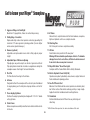
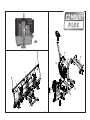
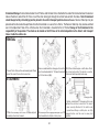
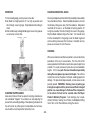
OPERATION and MAINTENANCE MANUAL
Insist on genuine Meyer Parts & Accessories
Important Information
Snow, despite the beauty it may impart to a bleak winter landscape,
poses the dual threat of inconvenience and danger. The environmental
conditions associated with snow, not to mention the health hazards and
economic loss it may impose, seriously endanger thousands of lives
annually. Business and industry suffer, and millions of snowbelt residents
may be affected by a single snowstorm.
Meyer Products LLC has published this manual to help you get the
maximum performance from your Meyer Snow Plow and familiarize you
with the features designed for efficiency and safety; be sure you recognize
and understand them. Follow recommended operation and maintenance
instructions, so when a storm hits, your Meyer Snow Plow will be ready
and you will know how to plow like a pro. DO NOT EQUIP ANY VEHICLE
WITH A SNOW PLOW WITHOUT CONSULTING MANUFACTURERS’
RECOMMENDATIONS.
Vehicles with Meyer Snow Plows installed may be so equipped as to
meet vehicle manufacturers’ specifications and recommended options
for snow plowing use. Most vehicle manufacturers insist that vehicles
which are to be used for snow plowing be equipped with certain
options and accessories, and it is so stated in vehicle manufacturer
specifications for snow plow application.
We also recommended that, for optimum performance, vehicles used
for snow plowing be equipped with:
• Four Wheel Drive
• Minimum 60 Amp Alternator or Larger
• Minimum 70 Battery of Larger (550 C.C.A.)
• Mud and Snow Tires
• Increased Radiator Cooling
• Automatic Transmission
• Power Brakes
• Power Steering
Under the continuing Meyer Products Improvement Plan, Meyer Products
LLC reserves the right to change design details and construction without
prior notice and without incurring any obligation.
IMPORTANT NOTICE: In conjunction with FMVSS (Federal Motor Vehicle Standard) and OEM (Original Equipment Manufacturer) guide lines, Meyer Products LLC
has designed this plow package with the following guidelines:
CAUTION: Installation of a snowplow mat affect your ner vehicle warranty. For more information consult your Vehicle Owners’ Manual / Vehicle Dealer.
WARNING: The vehicle must not be operated when overloaded. In all cases, the loaded vehicle weight, including th entire snowplow system, all aftermarket accessories, driver, passenger, options, nominal fluid levels, and cargo must not exeed the front/rear Gross Axle Weight Rating (GAWR), and total Gross Vehicle Weight
Rating (GVWR). These weight ratings are specified on the safetay compliance certification label on the driver’s side door opening. The use of rear ballast weight
may be required to prevent exceeding the front GAWR.
WARNING: Check your local/state/provincial laws regarding vehicle restrictions when the snowplow is not attached. These restrictions during specified times of the year
may require the removal of the mounting, lift frame, lift arm, hydraulic mechanism or any other fixtures or protruding surfaces mounted to the front of the vehicle.
Warning: Deployment of an air bag while using a Meyer snow plow will not be covered under Meyer Products’ warranty.
INSIST ON GENUINE MEYER
PARTS & ACCESSORIES
Table of Contents
Page
Get to Know Your Meyer Plus Snow Plow
2-3
Plus Specifications
4
Snow Plow Operation
5
Removing & Attaching Your Meyer E-Z Mount Plus™
6-7
General Maintenance & Adjustments
8-10
Diagnostic Trouble Shooting
11-18
Efficient Snow Clearance Starts with Planning
19
Keep Snow Under Control
19
Selecting Proper Size Snow Plowing Equipment
20
Hourly Snow Clearing Capacities
20
Plow with the Storm
21
Establishing Snow Clearance Plans
22
Snow Plowing Tips from the Pros
23
Snow Plowing in Open Areas
23
Parking Lots and Wide Driveways
24-25
Stacking Snow
25
Trapped & Residential Areas
25
Chemicals for Snow & Ice Control
26
Meyer Products Salt Spreaders
26-28
Meyer Accessories
29
Genuine Meyer Parts
30-31
Important Information
32
Warranty
Back Cover
• Protect your warranty
• Made to Meyer specifications
• Fit right
• Wear longer
• Perform better
• Your best value
SAFETY FIRST
Meyer Products recommends that this manual be read cover to cover so
that you are completely aware of all important safety recommendations.
Record your V-68 Serial number. This number is printed on the decal under
the hydraulic unit plastic cover.
For more information visit or contact:
www.meyerproducts.com
e-mail [email protected]
-1-
Get to know your Meyer® Snowplow
1. Aggressor Wings, Left and Right
Made from 12 gauge Steel, 4 lazer cut vertical ribs per wing.
9. Lift Frame
Allows for fast, complete removal of front end hardware, snow plow,
lights and hydraulic unit in one complete module.
2. Cutting Edge - Reversible
Replaceable high carbon steel provides extra long operating life;
should be 1/2” above ground in plowing position. (Can be higher
when used on gravel driveways.)
10. Attaching Pins
Pull 2 blue pins to remove complete assembly.
3. Runners (optional)
Adjustable and replaceable runners hold cutting edge at proper
height.
11. Lift Arm
Dual Chain locks in position to lift snow plow. *
Warning: Lift Arm extends beyond bumper of vehicle. To minimize
damage from a front end collision, Lift Arm should be removed
from vehicle when snow plow is removed.
4. Adjustable Super V Extension Springs
Tripedge give way when objects are struck at ground level. Note:
Trip spring tension should be checked on a regular basis during the
snowplow season. See Page 8 for more information.
12. Meyer Nite Saber® Snow Plow Lights
Complies with the Federal Motor Vehicle Safety Standards.
5. Pivot Pin
Pin that attaches the wings to the A-frame.
13. Electric Hydraulic Power Unit (V-68)
Operates snow plow hydraulically- raises, lowers, angles, holds and
floats moldboard in plowing position.
6. A-Frame
Designed to attach the snow plow to the vehicle, to pivot moldboard
for angle plowing, and to hold plow at proper distance in front of
vehicle.
14. Sno-Flo® Powder Coat
Baked on finish that looks like enamel, provides an extremely hard,
low friction surface that outlasts ordinary paint by a large margin.
Applied to all steel moldboards and mountings/frames.
7. Power Angling Cylinders
Positions the wings hydraulically at all angles with 1-1/2 x 12” double
acting cylinders.
15. Crankstand
Positions Moldboard and Lift Frame for easy attaching and
detaching.
8. Clevis Frame
Allows snow plow assembly to be attached or detached from vehicle
in minutes.
* With Lift Arm all the way down, the chains should have a little slack.
-2-
12
V68
11
8
9
1
13
5
1
10
7
3
2
4
7
6
7
6
-3-
SPECIFICATIONS
SV-8.5
SV-9.0
WEIGHT (TOTAL)
915 lbs.
955 lbs.
HEIGHT
30.5”
30.5”
LENGTH
102”
114”
MOLDBOARD GAUGE
#12
#12
VERTICAL RIBS/WING
4
4
TRIP SPRINGS
4
4
1/2” X 6”
1/2” X 6”
88”
98”
CUTTING EDGES
PLOWING WIDTH
AT FULL ANGLE
POWER ANGLING RAMS
NOTE: Shown with optional snow deflector
-4-
1-1/2” x 12” Double Acting
Snowplow Operation
Reset is accomplished by turning off the ignition switch or by turning
the power switch off momentarily and then back on. If the monitor
light is still illuminated after attempts to reset the switch have failed,
contact your nearest authorized Meyer Distributor for repairs.
HAND HELD CONTROLLER
The snow plow should only be in operation when the vehicle ignition
switch and the control switch are in the “ON” position. Care should
be taken to insure that the control switch is kept dry and free from
moisture during normal operation.
BACK/REAR
When the control switch is turned “On,” the on/off button will
illuminate. The individual touch pads operate the snow plow: (Up),
(Angle Left),(Left Extend), (Left Retract), (Angle Right), (Right Extend),
(Right Retract), (Scoop), (Vee) and (Down).
LEFT WING
CONTROL
SCOOP
MODE
Lowering of the snow plow an inch at a time is possible by tapping
the down arrow in short intervals. Holding down the down arrow
will activate a float light located next to the on/off button. This light
indicates the snow plow is now in the Lower/Float position. In this
position the snow plow will be able to follow the contour of the road
and the snow plow can also be angled to the left or right. Touching the
up arrow automatically cancels the Lower/Float position.
TOP/FRONT
FLOAT
MODE
ON/OFF
RIGHT WING
CONTROL
AUTO V MODE
UP/DOWN
LEFT/RIGHT
While angling left or right or raising the snow plow if the button is
pressed for more than six seconds the operation will be cancelled.
This feature eliminates unnecessary amp draw from the vehicle
charging system.
This handheld controller is self diagnosing. The systems monitor
light is located in the upper left corner next to the float light of the
controller. If the monitor light begins to flash the system is sensing a
malfunction. The number of flashes determines the exact location of
the potential problem. The diagnostic chart is conveniently located
on the back/rear of the handheld controller. See page 11-20 for more
detailed diagnostic information.
NOTE: The black wire with white stripe is the ground wire.
SYSTEMS
MONITOR
-5-
Removing and Attaching Plus Plow
pin. Reattach the Crankstand to the transport tube on the driver’s
side of the Lift Frame in the vertical, retracted position. Caution:
Crankstand must be secured at all times. Reattach the one
step electrical connection.
DETACHING THE COMPLETE ASSEMBLY
Leave control switch in lower float position and push down on
the Lift Arm. Disconnect the electrical plug. Attach Crankstand
to the adjustment tube on the side of the A-Frame using the
chained locking pin. Caution: Crankstand must be secured
at all times. Adjust the Crankstand down until the bottom of
stand touches the ground. Pull and twist the Blue Handle Pins
to disengage lift frame from clevis frame. If the pins do not pull
easily, adjust stand up or down slightly to remove tension on
the pins until they disengage. At this time the lift frame should
be leaning forward slightly, at rest on the top of the Crankstand.
Pull truck away.
ATTACHING THE COMPLETE ASSEMBLY
Check that Blue Handle Pins are disengaged. Drive the truck
up to the EZ-Mount Plus assembly centering the hood of
the truck to the lift arm to assure proper alignment with lift
frame guide plates until contact is made. Once contact is
made, drive forward, pushing the assembly a few inches. This
insures the lift frame is square to the Clevis Frame for proper
pin attachment. Adjust the Crankstand up until the front of the
truck raises slightly. Twist Blue Handle Pins so that the small leg
re-aligns with the slot, engaging the pins. The spring loaded pins
should snap into place. Note: If pins do not lock immediately,
move truck slightly forward and/or adjust the Crankstand up
or down until pins engage, or push the top of the Lift Frame
towards the truck locking the pins to the clevis frame. Remove
the Crankstand from the A-frame by removing the chained locking
Blue Handle
Crankstand
-6-
Crankstand Storage To store Crankstand on the Lift Frame slide the tube that is attached to the side of the Crankstand over the receiver
tube on the driver’s side of the Lift Frame. Insert the chain locking pin through the vertical holes on both the tubes. Note: Crankstand
should always be fully retracted (up) and be pinned in the vertical transport position when not in use. Receiver Tube Cap may be
placed over the driver side transport tube while the Crankstand is in use on the A-Frame. The Receiver Tube Cap may also be switched
over to the Adjustment Tube of the A-Frame when the Crankstand is mounted to the Lift Frame. Storage of the Crankstand is the
responsibility of the operator. The stand can be stored on the lift frame in the retracted position to the driver’s side transport
tube or inside the vehicle cab.
REMOVAL
1 Lower Plow to float position and manually push lift arm
down. Disconnect the electrical connection.
2 Remove crankstand from storage position on the
side of mount and reattach to “A” frame. Crank until
front of truck rises slightly.
3 Pull, then rotate blue pins on both sides of truck
into locked out position. The vehicle is now free
from mount and may safely back away.
ATTACHMENT
Storage position
1 Drive into assembly until contact is made and push
assembly a few inches forward.
3 Return crankstand to storage position and
reattach the electrical connection. The mount
is now securely attached to the vehicle and
is operational.Always confirm pins are fully
2 Rotate blue pins until engaged and push top of lift engaged before over the road or snow plow
frame towards truck until pins click in place.
operation.
-7-
General Maintenance
SNOWPLOW
CAUTION: ALWAYS LOWER MOLDBOARD TO THE GROUND
WHEN SNOW PLOW IS BEING SERVICED OR WHEN
VEHICLE IS NOT IN USE.
Check the V-68 Diagnosis chart, pages 11-18, respectively and
Post Season Maintenance, page 9, for advice on maintaining
the unit.
1. Check and maintain hydraulic fluid reservoir level to Full.
Oil level should be checked with lift ram down or retracted
position.
2. Check entire hydraulic system for leaks. A significant drop in
hydraulic fluid level is evidence of a leak which must be corrected
to prevent serious damage.
3. Before and after each season, remove moldboard center pivot
pin, thoroughly grease pivot pin and reinstall. Lubricate all pivot
points with chassis lube.
4. ADJUSTING TRIP SPRING TENSION - Tighten top locknut
4 turns beyond the point when spring coils begin to separate.
Tighten bottom locknut to hold eye bolt in position as shown
in figure 1.
Meyer Products LLC recommends this maintenance information
for regular service. Sustained heavy operation may call for more
frequent service. Snow plowing subjects a vehicle to exceptionally
rugged use. As a result, it is very important to inspect and bring
the snow plow and vehicle up to maximum operating conditions.
Inspection should be made of both the vehicle and snowplow
prior to the plowing season and after each use.
Pre-season Maintenance
Scheduled vehicle maintenance should be performed as
recommended by the manufacturer.
Don’t forget that in addition to keeping equipment in order:
1. Keep windshield wipers, heaters and lights working.
2. Use emergency flasher lights for increased visibility and safety.
3. Equip vehicles with chains where necessary.
4. Provide operators with protective clothing and with rubber
gloves for handling snow melting chemicals.
VEHICLE ELECTRICAL SYSTEM
For maximum efficiency, the vehicle supporting the snow plow
must be properly serviced. The system should consist of at
least a 70 amp./hr. battery and a 60 amp alternator. Be sure to
check regularly:
1. Battery terminals to assure they’re clean and free of
corrosion.
2. Electrical connections, to assure they’re tight and corrosion
free.
3. Battery must be in top operating condition.
4. Alternator and regulator, to assure maximum electrical output.
Figure 1
-8-
5. RUNNERS (optional)
A. Inspect moldboard runners for wear and height adjustment.
B. Always replace runners as soon as they start to wear through.
C. Adjust the runners to maintain cutting edge height of 1/2”
above ground in snow plowing position. (Can be set higher when
used on gravel driveways).
6. CUTTING EDGE - REVERSIBLE
Replace the cutting edge as soon as it appears worn. This will
prevent permanent damage to the tripedge.
7. MOUNTING BOLTS
Retighten all mounting bolts after first snow plowing session and
at regular intervals through the season.
8. SNO-FLO® POWDER COATING, both black and yellow,
should be checked at the beginning and end of each season
for any signs of rust. If any exists, use Meyer special Sno-Flo®
powder coat touch-up available in spray cans.
NOTE: PROTECTION AGAINST RUST AND CORROSION
When the power unit is not used for extended periods, protect
the chromed lift rod by fully extending and coating it with
chassis lubricant. Coat the exposed portions of the power
angling cylinder rods with chassis lubricant to protect against
corrosion.
and purge cylinders and hoses of all hydraulic fluid. The complete
system should then be flushed out with Meyer M-2 Flushing Fluid
before adding new Meyer Hydraulic Fluid.
2. Meyer M-1 Hydraulic Fluid is specially formulated with
an anti-ice additive for almost constant viscosity in subzero
temperatures. Because it is free-flowing in extreme cold, the unit’s
performance and efficiency are not affected by winter weather.
It is effective for a maximum of one year. Always carry an extra
quart of Meyer M-1 Hydraulic Fluid. Use of any inferior fluids
will void the Meyer warranty.
3. Refill power unit with Meyer M-1 Hydraulic Fluid by fully
retracting lift piston and mounting cylinder and filling reservoir
to top. Note: Do not over fill unit, over filling unit will cause oil
to squirt out of the reservoir pressure relief valve. Power angling
rams should be collapsed. Install Hydraulic unit and Moldboard
assembly on vehicle. Remove reservoir pressurerelief valve (Filler
plug). To bleed air from the system power angle wings side to side
while maintaining a constant check on the reservoir fluid level.
Note: It may be necessary to bleed air from the Power angling
cylinders by loosening the hydraulic fittings. Extend and retract
wings until you have a steady stream of oil coming out of fitting.
Raise and lower the plow several times. With lift ram fully
retracted (down) check fluid level and replace filler plug.
Post Season Summer Maintenance
1. Draining & Replacing Meyer M-1 Hydraulic Fluid
Drain the fluid by removing the drain plug located on the bottom
of unit. To drain the fluid from the power angling cylinders,
disconnect the fittings and completely retract the cylinder rods
-9-
SNOW PLOW STORAGE
1. When snow plow is disconnected, disconnect lift chains
from lift arm and extend lift cylinder to end of stroke and
coat chrome rod with light grease. This fills the cylinder with
hydraulic fluid and protects the interior and exterior from rust
and corrosion.
2. Whenever Moldboard is disconnected, coat the exposed
portions of the power angling cylinder chrome rods with light
grease to protect them from corrosion.
3. Coat pivot pin and other wear points with chassis lubricant.
Be sure to grease all grease holes.
4. Unplug electical connection at power unit. Coat connection
with a dielectric compound to prevent corrosion and plug into
their corresponding weather plug.
5. Reference post season summer maintenance on page 9 prior
to final storage.
-10-
DIAGNOSTIC
TROUBLE SHOOTING
These charts are intended to be used as an aid in diagnosing problems on the V-68 Meyer Hydraulic Power Units. They are not a
substitute for factory training and experience. Be certain to read the General Information and Testing Tips sections before attempting
any troubleshooting.
TESTING TIPS
Many tests do not require removing the Power Unit from the vehicle. However, more thorough testing can be done by using the Meyer
Test Stand which allows direct pressure and Amperage readings.
1. Use a screwdriver or other small tool to check for magnetism of solenoid coils (“S1,” “S2,” “S3,” “S5,” “S6” & “S7”). Place the tool
on the coil and have an assistant operate the switch. You should feel strong magnetic attraction.
2. Use a test light or volt meter to determine whether there is power at harness or Super-V controller.
3. When determining Amp draw of motor, always obtain the highest value possible, i.e., at maximum raise or angle with motor running.
4. The pump shaft of a good pump can be turned smoothly using two fingers. If it can’t be turned easily, the pump must be replaced.
6. Pump pressure can be measured at an angle hose (note pressure at full angle).
7.If hydraulic system is contaminated it is recommended that the hydraulic unit, power angling rams and hoses be drained and flushed
with M-2 flush fluid. The system should then be refilled with Meyer M-1 oil. See page 9.
-11-
-12-
-13-
-14-
-15-
-16-
-17-
-18-
Efficient Snow Clearance Starts with Planning
KEEP SNOW UNDER CONTROL
Deep or heavy, wet snow, because of its increased weight, calls
for more skillful and powerful plowing than light powder snow.
Here is where your Meyer Super-V gives you a big advantage
over a straight blade. Set the Super-V to the “ ” position and
proceed to open a single path that will allow you to work the
remainder of the area. Always plow in LOW gear and keep
plowing. Remember that wet snow weighs about 12 pounds per
cubic foot. As it piles up in front of a snowplow blade, the weight
can quickly increase to several tons.
PREPARING AREAS, USE OF GUIDE MARKERS
Every area to be plowed should be inspected before snowfall
for potential hazards. Holes should be repaired, raised manhole
covers leveled or noted and obstructions noted to prevent
damage to the plow mounting or vehicle undercarriage.
V
Markers or stakes with reflectors should be in position to indicate
boundaries of areas to be plowed, location of shut-off valves,
catch basins and other hazards. Markers should be at least three
feet above the ground; higher in areas of deeper snowfall.
Where packed snow or ice must be plowed, it is sometimes
necessary to lower the cutting blade to rest directly on the road
surface. In that situation, plow in lowest gear for greatest power
to the cutting edge. This method also prevents the plow from
“climbing over” the icy surface.
The first step in organizing an efficient plan is to prepare a
map or procure a blueprint of the area. Locate and mark all
utilities, outlets, shutoffs, catch basins and possible emergency
equipment that must be reached from outside.
Figure the square footage of each area and the total area.
Especially note areas from which snow will have to be carried,
called “trapped” areas. Although hauling is expensive, it is
necessary where piled snow would limit access. Indicate clearing
priorities on your map.This may aid you in preparing a priority
plan for your clearance operation.
If plowing very deep snow, 12 inches or more, you may have to
plow with the blade partially raised to shear off successive layers
of snow until a working area is clear. Then work small “bites” into
the edge. The “bite” depth should be inversely proportional to the
snow depth. A rule of thumb: 6-inch snow may be plowed with
the entire blade width; 9-inch snow with 3/4 of the blade width;
and 12-inch snow with only 1/2 of the width. Experience will
show what work can be done without stalling or getting stuck.
-19-
Selecting Equipment
Careful analysis of the area you intend to clear of snow will
direct you to the types of equipment you’ll require. Check Table
1, Average Hourly Snow Clearing Capacities, for recommended
equipment depending upon the area in which you’ll be working.
Where you plan to plow, and the conditions under which you will
be plowing, determine to a great extent the type of vehicle you’ll
find most useful. In general, three types of vehicles are available
as the power source of snow clearance. Each type has certain
inherent advantages depending upon the particular
situation.
Then, match the vehicles you already have with the snow removal
equipment you need. If your vehicles do not have the capacity
to clear all major access areas within two hours, you should
increase clearing capacity with additional equipment or arrange
for assistance through a contract plowing service.
Four-wheel drive HEAVY DUTY TRUCKS have proven most
effective in heavy duty snow plowing situations using the SuperV. They have excellent traction and the Super-V handles with
ease.
AVERAGE HOURLY SNOW CLEARING CAPACITIES*
TABLE 1 (Based on Straight Blades)
Two-wheel drive TRUCKS, particularly those of 1 to 3 tons, are
best for straight line road clearance and in large open areas.
Meyer Snowplow’s custom design for specific vehicles provides
the advantage of easy, fast attaching and detaching. This feature
permits utilization of vehicle versatility as weather conditions and
job requirements demand.
20 m.p.h. is a maximum snow plowing speed under ideal
conditions, assuming the driver is familiar with the roadway or
area to be cleared. Under unfamiliar or hazardous conditions, or
if there is poor visibility, we recommend reduced speed and
extreme caution.
Straight Line
(no. of miles
Trapped Area of roadway
(sq. ft.)
Cleared in
2 passes)
Snow
Plow size
Open Area
(sq. ft.)
4 Wheel Drive
Utility Vehicles
7 foot
6 1/2 foot
33,000
53,000
25,000
21,500
2 1/2 miles
5
Trucks
1 1/2 - 1 Ton
(2 WD)
7 - 7 -1/2 foot 38,000
19,000
4
(4 WD)
1 1/2 - 2 Ton
2 1/2 - 3 Ton
7-8 foot
88.000
8 1/2 - 9 foot 67,500
10 foot
67.500
42,500
30.000
~
6
7 1/2 **
10 **
* Based upon regional interviews with knowledgeable contractors
(6’ snowfall cleared by operators with average ability)
** Based upon recommended maximum plowing speed of 20 mph.
~ Not recommended for use except in very large areas of this type.
Use the 1 1/2 ton figures if necessary
-20-
Plow with the Storm
Angle Moldboard for Optimum Results.
The Meyer Super-V will provide a significant advantage when
plowing deeper snow in a straight path. Once you have made the
first path using the Super-V in the pointed or arrowhead position,
you can proceed to finish using straight blade procedures. Set
the moldboard at the best angle for rolling snow sideways in the
desired direction. The snow plow path, in the angled position,
should exceed the tire track by at least six inches on either side.
Be sure to have enough slack in the lift chain while plowing so
the cutting edge of the moldboard can follow the ground contour.
Use the adjustable runner shoes to set the bottom edge of the
plow just above the ground for best operation.
Plow with the Storm
It is of utmost importance to remember one basic rule — Always
plow with the storm. Start plowing when snow is 1 to 4 inches
deep, depending upon traffic or other limitations. Heavy wet
snow can be very hazardous when just 1 inch is on the ground.
Accumulations of more than 4 inches can be very difficult to
clear.
Snow is heaviest when wet, and most difficult to handle. The
National Weather Service reports that a 6-inch, average weight
snowfall on a 200 x 200 foot parking lot weighs 62 tons. Heavy,
wet snow for the same area might weigh as much as 248 tons.
If the heavy snow had to be hauled away, you’d need 74 full
loads on a l0-yard truck.
Obviously, the only way to assure clear traffic areas is to be
prepared with the proper equipment and expertise to open
arteries and areas to traffic. Remember to keep current with
accurate snowfall information from local weather bureaus via
radio and television.
-21-
Two Established Snow Clearance Plans
These two snow plowing techniques have been time- and
operation-tested. Use them as guidelines for most snow
plowing strategies. Plan I is for smaller areas of 50,000 sq.ft.
or less. Plan II is for larger establishments having more than
50,000 sq.ft. to be cleared.
3. Have vehicles and equipment inspected, fueled and ready.
Recommended equipment: A four wheel drive vehicle; a SV8.5 or
SV9.5 snow plow; snow shovels; and ice control equipment.
4. Clear area by pushing snow first to sides of drives, around
perimeters of parking areas and away from loading docks and
platforms. It is often true that the smaller the establishment,
the greater the proportion of “trapped” areaswhich will require
snow to be hauled away. Always deposit snow as far back as
possible for greatest use of dumping areas.
5. Use snow shovels to clear walks, gates and doorways.6.
Treat with snow-melting materials as needed.
Recommended procedure: PLOW WITH THE STORM.
PLAN II (over 50,000 sq.ft.)
Begin plowing at the suggested accumulation for your type of
establishment (i.e., 1” for commercial and institutional areas; 2”
for industrial establishments; 3” for municipal and residential
areas.) Continue until snow has been cleared. Don’t forget
- snowfall often surpasses weather forecasts. A well planned
clearing schedule will help prevent the necessity for expensive
emergency action.
Recommended equipment: The suggested number of vehicles,
according to the Table “Average Hourly Snow Clearing
Capacities”, on page 20, with SV8.5 or SV9.5 snow plows;
front end loaders if needed; snow shovels and ice control
equipment.
PLAN I (less than 50,000 sq. ft.)
Recommended procedure: As always, PLOW WITH THE
STORM. Begin plowing at the suggested accumulation for
the area and continue as required. Actual snowfall frequently
exceeds forecasted conditions. Well-planned snow clearance
strategy reduces the chances for expensive emergency action.
Snow Plowing Tips from the Pros
A typical small-area strategy:
1. Keep in touch with local weather forecasts for preparatory
measures.
2. Notify scheduled personnel.
-22-
Snow Plowing Tips from the Pros
SNOW PLOWING OPEN AREAS
Open areas such as parking lots require a more serious approach
to planning, where to begin, and where snow can be stacked at
the edges. The following will help in making a plan, thus turning
out a neat, professional job.
On a dirt or slag surface, drop moldboard to ground in straight
position, then raise one inch or adjust runners for desired
clearance. Under extreme surface conditions it may be necessary
to plow with moldboard in suspended position.
PARKING LOTS
Always turn on warning flashers and/or use yellow warning
beacon or strobe light when plowing. Then make a single pass
down the center on the longest dimension. Angle plow the snow
toward the long sides with continuous passes until the area is
cleared and snow is all stacked around the outside edges.
1. Always turn on warning flashers when plowing.
2. Make first pass to clear area into which you will later push
more snow.
3. Clear front in straight position and clean up remaining
snow. Buck piles from either side to stack snow. Blade will
automatically “ride” up pile to aid in stacking.
4. Set the Super-V in the “V” or scooped position to clear between
parked cars or areas where it is necessary to make short
passes without snow spill over.
For larger areas, efficient plowing calls for clearing area
immediately in front of buildings and working away from buildings
toward the outer limits of the area. When snow is quite deep,
it might be necessary to push the excess into piles out of main
traffic lanes for later handling. Areas 100,000 sq.ft. or more
— once the main artery is clear, it is usually most efficient to plow
at right angles to the artery, piling up windrows by back and forth
passes in alternate lanes. The windrows can later be pushed out
of the way or left as is depending upon conditions.
To clean up remaining snow, you can put the blade in the straight
position. Buck piles from either side to stack snow. The blade
will automatically “ride” up the pile to make stacking easier.
-23-
WIDE DRIVEWAY
STRAIGHT LINE SNOW PLOWING
This method is most efficient for streets and roads. V type
snowplows mounted on heavy utility vehicles or service trucks
are excellent for such an operation.
1. Make one pass down center with blade in “ ” position.
V
2. Push snow to side with moldboard in straight position &
angled right or left.
Set the snow plow moldboard at an angle so that the snow is
rolled to the shoulder or curb.
3. Do the same on either side.
Single lane roads and aisles can often be cleared with one
pass.
When the road is more than twice the moldboard’s width, plow
a center lane for the first full pass. Then, in follow-up passes,
work the snow to the sides. The diagram illustrates plowing
sequence for a typical 20-foot road.
Corner clearing is almost automatic when clearing intersecting
streets. When snow is heavy, a little “stop over” snow may have
to be removed from intersections by additional short passes.
We recommend a speed of 5 to 15 MPH for this kind of plowing.
Of course, road surface, weather conditions and equipment will
influence your speed.
Plow with the storm.
-24-
DRIVEWAYS
CLEARING RESIDENTIAL AREAS
1. Plow toward garage pushing snow to one side.
2. Set blade to straight position, lift it as high as possible and
drive through snow to garage. Drop blade and back drag to
street.
3. Back into driveway and angle blade again. Use as many passes
as necessary to clear drive.
Driveways and aprons are most efficiently cleared by maneuverable
four wheel drive vehicles. Recommended procedure is to enter
the driveway rolling snow away from the residence. Stop about
two-thirds of the way in, set the blade in bucking position, lift
as high as possible, then drive through the snow to the garage.
Drop the blade and back drag to the street. Turn around, back
into the cleared path to the garage, reset the blade angle and
continue rolling snow away from the house. Complete as many
passes as necessary to clear the snow.
STACKING
When snow clearance conditions are perfect, snow can be merely
pushed out of the way to unused areas. The first storm of the
season, plow back from the drive area to allow space to pile future
snowfall. It is usually necessary to pile snow up to considerable
heights. In that case, push the snow forward and upward by
raising the snow plow as you move into the pile. The vehicle’s
momentum will carry the plow into the pile, avoiding equipment
damage. The pile should slope outward, so later snows can be
pushed upward. WARNING: Stacking snow or pushing up
into high snow piles with the plow in Lower/Float or Angled
position can cause damage to the Snow Plow components
or the vehicle that will not be covered under the Meyer
Products Warranty Program. Such damage may include,
without limitation, twisting the A-Frame, the Moldboard hitting
the Lift Arm, or the Plow Markers striking the vehicle.
CLEARING TRAPPED AREAS
Areas where there is little or no space for stacking cleared snow
are considered “trapped.” An example is an area requiring full
access from surrounding buildings. Snow plowing techniques are
the same as for any other space of comparable size, but heavy
accumulations must be piled for removal by truck.
-25-
Chemicals for Snow and Ice
Meyer Spreaders
Except in very light snow, ice melting materials
should never be used in place of snow plowing.
However, in combination with trained personnel
and equipment, ice melting materials play an
important part in controlling ice and snow.
Whenever possible, apply ice melting materials
before a snowfall. You’ll use less, and it will be
more effective in preventing snow and ice from
adhearing to the pavement surface and less
damaging for the environment. You may have to
increase the use of ice melting materials at night
and as temperatures fall.
Hotshot ™(38100) &Hotshot HD™ (38110)
The Meyer Hotshot spreaders promise to last season after season.
These Spreaders are available in steel and stainless steel (HD). Both
use a polypropylene hopper with a capacity to hold 1.3 c.f. / 70lbs
of salt, sand seed or any other free flowing material. Other features
include; infinitely adjustable feed gate (up to 12 foot wide pattern),
pneumatic tires and weather resistant fitted hopper covers which will
keep the spreader material dry and contained in the hopper.
Mini Jr. (36006)
The Meyer Mini Jr (5.75cu.ft.) is an ideal solution for small and medium
sized jobs: walkways, intersections, access ramps and parking lots.
The no rust thermoplastic hopper and internal vertical spiral auger
provide continuos and even flow of material.
Adjustable controls allow spreading of #1 rock salt from 3 to 30 feet.
Easy to attach and detach. The Mini Jr. mounts to a standard 2” trailer
receiver hitch.
Experts agree a mixture of two parts mixed ice
melting materials (1:3 calcium chloride to salt, by
weight) mixed with one part abrasive (cinder, sand
or slag) is more effective than rock salt alone in
melting snow and ice below 30°F. One hundred
fifty pounds of such mixture with abrasives will
treat a 50,000 sq.ft. surface.
Blaster Spreader
350/350S
750/750S
The BlasterTM Spreader is a poly tailgate spreader, available in four
models that spread salt or salt & sand. What makes this spreader
unique is its 1/2 horsepower direct drive motor, it’s the most powerful
spreader motor available. The motor’s “Fast Blast” feature can produce
up to 70 amps of surge power to grind through chunks of salt or
sand. The 750- and 350-pound hoppers are made of extended life
polyethylene and are backed by Meyer’s exclusive 3 + 5 year ROC
Solid Warranty. Variable speed control allows for precise material
spread pattern up to 40 feet.
It is imperative to treat priority areas such as hills,
heavy traffic areas, bridges and intersections first,
especially where snow may compact and adhere
to the road surface, causing icy road conditions. When slush begins to stiffen and refreeze,
it will be necessary to plow again and reapply
chemicals.
-26-
Under Tailgate Spreader
MDV Spreader
9’ Carbon Steel (63001)
9’ Stainless Steel (63004)
10’ Carbon Steel (63002)
10’ Stainless Steel (63005)
An extremely rugged truck accessory, the
Under-Tailgate Spreader is offered in two
models: a single auger or for ultimate
efficiency dual augers; each spreads
cinders, sand, salt or pea gravel. Attaches
easily under the tailgate of any standard
dump truck, yet will not obstruct dumping over the spreader. The spinner is
always in spreading position and can be
operated with the truck moving backward
or forward. Also available in stainless
steel and direct drive.
The MDV spreader expands your choice
between pickup size spreaders and the
large V-box units. The MDV bridges the gap
between the 15,000 GVW and the 20,000
GVW trucks. It can be powered by either
your truck’s central hydraulic system or its
own power source.
Mate XL (38000)
The Meyer Mate XL spreader holds
9 cubic feet of salt, sand or calcium
chloride and it can even spread seed
to extend its use beyond the snow
season. The Mate XL features a thermoplastic no-steel frame for long-lasting
protection from corrosion. The Mate
XL is powered from a 1/6thH.P. 12VDC
motor with in-cab variable speed
control which will spread material up
to 30’. A vibrator is standard on the
XL model. The Mate XL requires NO
drilling and is quickly attached and detached from any full size pick-up truck.
Adjustable controls allow spreading of
bagged#1 rock salt from 3 to 30 feet.
Replaceable Tailgate Spreader
This replaceable tailgate spreadermounts easily on most
one-tondump bodies by simply replacing theexisting tailgate. Designed to spreadfree-flowing chemicals, salt and/orsand throughout its entire width, thereplaceable tailgate spreader canspread in
widths from 4’ to 40’. Ahost of optional equipment allowsyou to
customize the spreader to fitmost any job requirement.
Visit www.meyerproducts.com for more information
-27-
Insert Hopper Spreaders
1.8 cu. yd. Carbon Steel (62991),1.8
cu. yd. Stainless Steel (63006),2.0
cu. yd. Carbon Steel (62992),2.0 cu.
yd. Stainles Steel (63007)
The Meyer 1.8 & 2.0 cubic yard capacityV-box spreader for pickup trucks
mountsand stores as a single unit. This
m e c h a n i c a l l y - o p e r a t e d s p re a d e r i s
powered by an electric start 10 H.P.
gas engine, which drives a high torque
orbital-type motor and a 20:1 ratio gearbox.
Spinner and drag chain speeds work in
unison with engine R.P.M. The spinner will
evenly spread material from four (4) to thirty
(30) feet. In-cab controls make operation
easy.
PolyHawk
This one-piece polyethylene hopper fits most 3/4 ton pickup truck beds and
provides all the robust performance qualities of conventional V-box spreaders,
but with less weight, greater capacity, longer life and less maintenance. The
PolyHawk holds 37% more material than competitive poly spreaders. Another
key feature of the PolyHawk™ is the swing-up spinner assembly. The swing
up spinner allows for simplified clean-up and easy seasonal storage. The Poly
Hawk is equipped with a top screen and a 16” wide stainless steel conveyor
that provides reliable material handling control and has a replaceable stainless
steel conveyor floor. Overlapping baffles, 2 internal and 4 external, and a 13”
poly spinner disc provide precise material spreading. A 10 HP 4-cycle engine
is standard and an 11 HP 4-cycle is available as an option.
Ice Hawk
This innovative configuration comes complete
with its own, built-in hydraulics system! This
self-contained v-box spreader unit can be
initially installed in 2-3 hours and re-installs in
only 30 minutes, literally providing plug-n-go
installation. Plus, the Ice Hawk eliminates both
the need to install costly hydraulic systems in
each truck and the common shortcomings of
engine driven vboxspreaders, while providing
unsurpassed spreader performance. Thus
allowing you to spend more time on the road
- and less time in the maintenance garage.
STCC
The Tailgate Cross Conveyor (TCC) provides for the most efficient method
of distributing granular materials available today. This sturdy cross conveyor
will perform dozens of jobs while saving on labor, time and materials. Every
municipality,contractor, utility and construction company can benefit from the
TCC cost efficient material handler. The cross conveyor transfers material left
or right allowing for multiple uses. The TCC mounts directly to dump box with
quick disconnect pins. Unit mounting allows for dumping over or parallel-toground positioning. Conveys most free flowing material.
-28-
Meyer Accessories
M-1 Hydraulic Fluid
Snow Deflector
Keep your Meyer Electro-Touch® snow plow
control system operating at peak performance;
change hydraulic fluid yearly. Meyer M-1
Hydraulic Fluid has additives that insure peak
efficient operation of all Meyer electric hydraulic
power units (15134).
Available in specific sizes to fit all Meyer
moldboards. Kits come with attaching parts.
Deflects snow flume down and away from
windshield area. 8-1/2’ (12579) 9-1/2’ (12643).
Hydra-Flush®
Hydra-Flush™ advanced technology maintains
your lift’s maximum performance by removing contaminants and performance robbing
deposits. Hydra-Flush™ protects and preserves
the life of your pump, seals, o-rings, and hoses.
It is ideal for off-season storage (15901).
Winch Kits
E-ZMount Plus (16529)
Lock Pin
Protect your Meyer Snow Plow
components with this sturdy, durable stainless
steel and brass lock pin. Available for the QuikLift or Electro-Touch power units. Quik-lift - 2”
long (07694C) Electro-lift - 3” long (07695C)
Sno•flo®Powder CoatTouch-Up Paint
Super-smooth high gloss paint especially
formulated for use on powder coat finishes.
Available in 12 oz. aerosol cans. Black (07026)
Yellow (07027) & 1 qt. brush-on (07181).
Visit www.meyerproducts.com for more information
-29-
FAST MOVING PARTS LIST
HOSE & HOSE FITTINGS
22675
HOSE 1/4 X 9 -1/4” SAE-6
22420
HOSE 1/4 X 33” SAE-6
22418
HOSE 3/8 X 33” SAE-6
22676
FITTING SAE-6 90° ELBOW
22460
FITTING SAE-6 90° ELBOW
CUTTING EDGES - (STEEL)
09218
(2) SV 8.5
09219
(2) SV 9.5
CUTTING EDGE NUTS & BOLTS (STEEL)
21943
(10) BOLT
20307
(10) LOCKNUT
COUPLER’S HOSE END (optional)
22443
FEMALE COUPLER SAE-6
22444
MALE COUPLER SAE-6
SNOWPLOW HARDWARE
09124
EYE BOLT & NUTS
07215
TRIP SPRING
08852
MARKER KIT
12557
PIVOT PIN
COUPLER’S ANGLE CYLINDER (optional)
22442
MALE COUPLER SAE-6
FEMALE COUPLER SAE-6
22445
RUNNERS & SPINDLES
09214
(OPTIONAL) RUNNER KIT COMPLETE
12394
MUSHROOM SHOE CASTING ASSY
12449
RUNNER SPACER
20363
WASHER
22083
LINCHPIN
SNOW DEFLECTOR KITS (RUBBER) (optional)
FOR STEEL MOLDBOARDS
12579
SV-8.5 KIT
12535
SV-8.5 DRIVER SIDE
12644
SV-8.5 PASSENGER SIDE
12643
SV-9.5 KIT
12641
SV-9.5 DRIVER SIDE
12646
SV-9.5 PASSENGER SIDE
A-FRAMES
13755
SUPER-V A-FRAME
ELECTRIC/HYDRAULIC POWER
15047
V-68 / E-88 BASE SEAL KIT
15048
SUPER-V VALVE BLOCK SEAL KIT
15049
UNIVERSAL VALVE BLOCK SEAL KIT
15051
V-68 MASTER SEAL KIT
LIFT CYLINDER
05815
1-3/4” X 8” SAE 6
POWER ANGLING CYLINDERS
07186
1-1/2” X 12” SAE-6 ANGLE RAM DOUBLE ACTING
MISC. POWER UNIT
15727
MOTOR (ISKRA) TWO TERMINAL E-78/E-88
15854
BRUSH KIT - ISKRA
ANGLING CYLINDER SEAL KITS
07171
SEAL KIT 1-1/2” X 12” SAE-6 ANGLE RAM DOUBLE ACTING
-30-
V-68 POWER UNIT PARTS
15925
S1 SOLENOID ASSY.
15917
S1 VALVE
15044
S2 SOLENOID ASSY.
15055
S2 VALVE
15926
S5 & S6 SOLENOID ASSY.
15918
S5 & S6 VALVE
15927
S3 SOLENOID ASSY.
15919
S3 VALVE
15987
S7 SOLENOID ASSY.
15958
S7 VALVE
15916
ALL COILS
15011
FRONT COVER
15010
REAR COVER
PAINT - TOUCH UP
07026
BLACK AEROSOL (1)
BLACK AEROSOL (12)
08676
07027
SNO-FLO AEROSOL (1) YE
08677
SNO-FLO AEROSOL (12) YE
07028
SNO-FLO BRUSH-ON .6 OZ. (1) YE
08678
SNO-FLO BRUSH-ON .6 OZ.(12) YE
07066
SNO-FLO - QT. (1) YE
08686
SNO-FLO - QT. (12) YE
HYDRAULIC FLUID
15134
M-1 FLUID QUART
15487
M-1 FLUID 12 QT. CASE
15902
M-2 FLUSH FLUID
CONTROLLER
22695
SUPER-V CONTROLLER
Visit www.meyerproducts.com for more information
HARNESS
22696
PLOWSIDE
22691
TRUCKSIDE
LIGHTS
07224
07225
PLOW LIGHT - PASSENGER
PLOW LIGHT - DRIVER
NOTE: ELECTRICAL REPLACEMENT PARTS LISTED ABOVE
ARE FOR 12 VOLT SYSTEMS ONLY.
-31-
Thank you for buying the best built, best backed plow in the industry. In order to expedite customer service and warranty registration
please complete the below information and have it ready to register your product on line at www.meyerproducts.com
www.meyerproducts.com
Where Purchased
Your Personal Plow Information
Company __________________________________________
Vehicle Brand _________________________________________
City _______________________________________________
Vehicle Model _________________________________________
State ______________________________________________
Vehicle Year ___________________________________________
Zip ________________________________________________
Date Purchased _________ / _________ / _______________
mm
day
Type of Store
Truck Equipment Distributor
Automotive Dealership
Power Equipment Store
Other ________________________
Vehicle Vin #
year
Hydraulic Serial #
Moldboard Serial #
MEYER®/DIAMOND® SNOW PLOWS
LIMITED WARRANTY
continued from reverse side
The original purchaser’s sole and exclusive remedy against Meyer Products LLC, and Meyer Products
LLC’s sole obligation for any and all claims, whether for breach of contract, warranty, tort (including
negligence) or otherwise shall be limited to providing, through its authorized Distributor/Dealer network,
all labor and/or parts necessary to correct such defects free of charge. Any cost incurred in returning
the product to an authorized Meyer®/Diamond® Distributor/Dealer is the responsibility of the original
purchaser. ALL EXPRESS AND IMPLIED WARRANTIES FOR THE PRODUCT, INCLUDING, WITHOUT
LIMITATION, ANY IMPLIED WARRANTIES OF MERCHANTABILITY AND FITNESS FOR A PARTICULAR PURPOSE, ARE LIMITED IN TIME TO THE TERM OF THE LIMITED WARRANTY PERIOD. NO
WARRANTIES, WHETHER EXPRESS OR IMPLIED, WILL APPLY AFTER THE LIMITED WARRANTY
PERIOD HAS EXPIRED. Meyer Products LLC disclaims liability beyond the remedies provided for
in this limited warranty, and disclaims all liability for incidental, consequential, and special damages,
including, without limitation, any liability for third-party claims against you for damages, for products
not being available for use, or for lost profits. Meyer Products LLC’s liability will be no more than the
amount you paid for the product that is the subject of a claim; this is the maximum amount for which
we are responsible. Some states do not allow the exclusion or limitation of incidental or consequential
damages, so the above limitation or exclusion may not apply to you.
How To Get Service:
In order to obtain service under this warranty, the original purchaser must:
• Use all reasonable means to protect the complete snow plow package from further damage;
• Return the claimed defective part to the Meyer®/Diamond® Distributor/Dealer from whom the product was purchased or to any authorized Meyer®/Diamond® Distributor/Dealer, transportation and
freight charges prepaid. Only Meyer®/Diamond® Distributors/Dealers are authorized to perform the
obligations under this warranty. For the address and telephone number of the Meyer®/Diamond®
Distributor/Dealer nearest you, go to www.meyerproducts.com, check the telephone directory or you
may write to Meyer Products LLC at the address below, or call (216) 486-1313 for assistance;
• Provide maintenance record and receipts for required maintenance, if requested;
• Allow inspection of damaged parts and/or complete snow plow package if deemed necessary by
Meyer Products LLC
• It is the responsibility of the original purchaser to establish the warranty period by verifying the
original delivery date. A bill of sale, cancelled check or some other appropriate payment record
may be kept for that purpose. It is recommended, but not required, that the consumer verify the
original delivery date by immediately returning the attached Warranty Registration Card.
How State Law Applies:
This warranty gives you specific legal rights, and you may also have other rights which vary from
state to state.
MEYER PRODUCTS LLC
18513 Euclid Avenue • Cleveland, Ohio 44112-1084
www.meyerproducts.com • e-mail [email protected]
Form No. 4-546R1
408 7.5C
Printed in the U.S.A. ©2008
MEYER PRODUCTS LLC
18513 Euclid Avenue • Cleveland, Ohio 44112-1084
www.meyerproducts.com • e-mail [email protected]
Exclusions:
This warranty does not cover:
• Problems caused by failure to follow the product instructions, failure to maintain the product as
described in the Operator’s Manual, or failure to maintain proper levels of lubricants;
• Problems caused by contamination or restriction of lubricant systems, or damage resulting from
rust, corrosion, freezing or overheating;
• Paint, or expendable snow plow parts such as pins, runners, cutting edges, chrome plating, springs
and markers;
• Damage to any vehicle to which the products are mounted, or the suitability of any product for vehicles which are not fitted with the appropriate heavy-duty snow plow service preparation parts;
• Damage caused by usage that is not in accordance with product instructions (use of the snow plow
for any purpose other than plowing snow is considered misuse and abuse);
• Any snow plow, or any part, component, or assembly thereof, which has been modified or altered;
• Problems caused by using accessories, parts, or components not supplied by Meyer Products
LLC;
• Cost of tax, freight, transportation or storage charges, environmental charges, solvents, sealants,
lubricants or any other normal shop supplies.
• Problems caused by collision, fire, theft, vandalism, riot, explosion, lightning, earthquake, windstorm,
hail, water, flood, or any other Acts of God;
• Liability for damage to property, or injury to, or death of any person arising out of the operation,
maintenance or use of the covered product;
• Products with missing or altered serial numbers;
continued on reverse side
Customer Responsibilities:
Customer must keep the complete snow plow package serviced/maintained as recommended by
Meyer Products LLC A written record of service must be maintained, along with receipts for maintenance
materials purchased. A copy of the maintenance record and pertinent receipts may be requested in
the event of a claim.
Meyer Products LLC Responsibilities:
Meyer Products LLC will repair any product that proves to be defective in materials or workmanship.
In the event repair is not possible or practical (as determined by Meyer Products LLC in its sole discretion), Meyer Products LLC will either replace the product with a new product of similar model and
price, or refund the full purchase price, as determined by Meyer Products LLC
Warranty Period:
This warranty runs for a period of one year from the date of purchase for purchases of individual
parts,components, or accessories; and for a period of two years from the date of purchase for any
purchase of a complete Snow Plow Package; in each case for the original purchaser of the product.
Coverage terminates if you sell or otherwise transfer the product. Some states do not allow limitations
on how long an implied warranty lasts, so the above limitation may not apply to you.
Meyer Products LLC warrants to the original purchaser of Meyer® and Diamond® brand products
that they will be free from defects in materials or workmanship, with the exceptions stated below. No
person is authorized to change this warranty or to create any additional warranty on Meyer®/Diamond® products.
MEYER®/DIAMOND® SNOW PLOWS
LIMITED WARRANTY