1
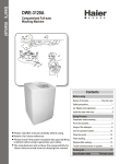
User Manual
1.
2.
3.
4.
5.
6.
7.
8.
9.
10.
11.
12.
13.
14.
15.
16.
17.
FEATURES:
Code Hopping and Code Learning.
Remote Starting.
Remote (silent) arming/disarming.
Starter disable (500mA negative
output when armed)
Auto re-arm.
Driving lock mode.
Car (silent) searching.
Audible intrusion zone identification.
Defective zone alert and by-pass.
Power failure memory.
Key-less entry.
Remote panic.
Anti-hijack.
Emergency reset.
Last Door Arming set by transmitter.
When triggered by sensor, the siren
will sound for 30 sec. and reset
automatically.
When triggered by door, trunk, hood
18.
19.
20.
21.
22.
23.
24.
25.
26.
27.
28.
29.
30.
or ACC the siren will sound for 60
seconds.
Built-in actuator’s relay.
Central locking, active time selectable– 0.5
or 3.5 seconds.
Two negatives and one positive trigger
input.
Plug-in dual zone shock sensor.
Pre-warn away.
Multi-function LED status indicator.
Inline fuse protection.
Remote trunk release (for optional trunk
opener system).
Windows close (for optional window closer
system).
Remote engine warm-up time (6 or 18
minutes.)
Programmable Gear Sensor.
Valet mode.
Turbo timer – 2 minutes.
ARMING:
When exiting the vehicle, press and release button (not over 2 seconds) siren will chirp
once to confirm arming. Lights flash once, doors lock, power windows roll-up (if installed)
and engine kill is enabled.
҇
DISARMING:
In armed mode, press and release button , siren will chirp twice, lights flash twice, doors
will unlock and engine kill disables.
҈
SILENT ARMING:
Press the button , the system will have no audible confirmation but lights will flash once.
҉
AUTO RE-ARMING:
After disarming the alarm system, if the car owner does not enter the vehicle and turn on the
ignition switch within 30 seconds, then after 20 seconds the alarm will re-arm.
DEFECTIVE ZONE ALERT & BY-PASS:
While arming the alarm, if the siren chirps 4 times (3 times for silent arming), this means that
there is a door not shut properly. The alarm will bypass that zone, however, it will still
protect other zones.
ALARM MODE & WARN AWAY:
will stop alarm trigger mode, and system will remain in armed
Pressing button
mode.
1. If the alarm is triggered by the first stage of the shock sensor, the siren will sound for 2
seconds.
2. If the car is tampered with or bumped into, the alarm will sound for 30 seconds and then
re-arm.
(In silent arm mode, the siren will not sound for being triggered by sensor)
҇Ε҈ʳ ̂̅ʳ ҉ʳ
1
3.
Ε
Ε
If door trunk hood is opened or ACC (ignition switch) is turned on, the system will
sound for 60 seconds.
INTRUSION IDENTIFICATION:
If the vehicle is tampered with or intruded, when disarming the alarm, the siren will chirp
different sounds to identify which zone has been tempered.
1. Second stage of sensor was triggered
3 chirps & 3 lights flash
2. Door hood was opened, or ACC was turned on 4 chirps & 4 lights flash
Ε
CAR (SILENT) SEARCHING:
Press button in arming mode, lights will flash once and siren will sound a long blare to
execute car-searching function.
Silent car searching: press button and it will only flash the lights to spot the vehicle.
҇ʳ
҉ʳ
REMOTE ANTI- HIJACK by TRANSMITTER:
While you were driving the car, press button for over 2 seconds, the system will activate
ANTI-HIJACK. The lamps will flash twice, and after 30 seconds the siren will sound and
lights will flash. After 15 seconds, the engine kill will activate and the engine will shut down.
After15 seconds, the windows will roll up and the doors will be locked (if all features are
installed).
To release this function; just press button
, the system will confirm and the LED will
turn off.
҇ʳ
҇ʳ ˴˺˴˼́
҇
REMOTE PANIC:
When ignition switch is off, press button
for over 2 seconds, the siren will sound and
lights will flash. After 60 seconds, alarm will return to previous status. However, pressing
button
again will turn off the panic mode rather than waiting for 60 seconds.
҇
DRIVING LOCK MODE:
Turn on ignition (all doors must be closed properly) and 2 second later the Central Door
Locking will be locked automatically.
2. Turn off ignition the Central Door Locking will be unlocked automatically.
3. Set / Release this function: Turn the ignition switch on, press button for 2 seconds1. One chirp
Driving lock mode is set (Factory default)
2. Two chirps
Driving lock mode is released
1.
҈
EMERGENCY KEY RESET:
1. If the remote is lost, or its battery become exhausted, the owner can enter the car by
using a code.
2. It can be set by the ignition switch:
A.) Open a door and pull the handbrake. (keep door open)
B.) Turn the ignition on/off 5 times (Each turn on/off must be finished within 1 second)
and this will disarm the alarm instantly.
REMOTE TRUNK RELEASE:
When ignition switch is off, press and hold button over 2 seconds, the system will open
the trunk. In arming mode, however, the system will enter disarming mode first before
opening the trunk.
Note: Disarming the alarm system in this way will not execute “Auto Re-arm” feature.
҈
2
LAST DOOR ARMING:
1. Whenever the ignition is turned from on to off and all doors are closed, after 20 seconds
the siren will echo 2 chirps (lamps flash twice) to remind the driver and 10 seconds later,
the system will lock the doors and enter armed mode automatically.
at the
2. Set / Release “last door arming”: Turn the ignition switch on, press button
same time for 2 seconds1. One chirp
Last door arming is set (Factory default)
2. Two chirps
Last door arming is released
҇ʹ҈
KEYLESS ENTRY WHILE IGNITION IS ON:
When driving the car, you can lock the door by pressing button
doors press button of transmitter.
҈ʳ
1.
2.
3.
4.
҇ of transmitter. To unlock the
TURN ON/OFF the VALET MODE:
Turn on the ignition switch; then press the button for over 2 seconds to activate the
valet mode.
The siren will chirp once and LED status light will be on.
In this mode, the system can only operate panic doors lock and 2nd channel output.
Turn on the ignition switch; then press the button over 2 seconds, the valet feature will
be turned off. In the meantime the LED will be turned off and siren will echo two chirps.
҉
Ε
҉
SOFTWARE GEAR SENSOR ON/OFF:
For manual transmission, programming is required.
҈ʾ҉ʳ
1. How to program the software gear sensor:
Turn on the ignition switch, press button
at the same time over 2 seconds.
1. One chirp Software gear sensor is on (for manual transmission car).
(Factory Default)
2. Two chirps Software gear sensor is off (for auto transmission car).
2. How to operate the software gear sensor:
When you are seated in the vehicle with the engine running and doors are closed, place
to
the shifter in the neutral position and pull up the handbrake. Press the button
activate running mode. In the meantime, the lights will turn on. Turn off the ignition
switch and remove the key from the ignition within 15 seconds; the engine will stop
immediately after the doors are closed. Siren will chirp once.
Note: if Turbo timer is on, the engine will stop after 2 minutes instead of right away.
Note: above purpose is assuring the manual transmission car will be in the neutral
position when leaving the vehicle.
Ζʳ
3. In the attempt to start the engine by the transmitter without these steps, the siren will
echo 6 chirps (5 chirps for silent arming) and vehicle will not start.
TURBO TIMER ON/OFF:
When you are seated behind the wheel, place the shifter in the neutral position and pull
up the handbrake. Press the button to activate keyless running mode. In the meantime,
the lights will turn on. Turn off the ignition switch and remove the key from the ignition;
the engine will stop after 2 minutes.
Turn on the ignition switch, press button
for over 2 seconds.
Ζ
Ζ
3
1.
2.
One chirp
Two chirps
Turbo timer is on
Turbo timer is off (Factory default)
REMOTE ENGINE START WARM-UP TIME:
This system has two options for start warm-up time - 6 or 18 minutes, which is
programmed by remote.
Turn on the ignition switch, press button
ʳ at the same time for over 2 seconds.
1. One chirp
Remote engine start warm-up for 18 minutes
2. Two chirps Remote engine start warm-up for 6 minutes (Factory default)
҇ʾ҉
POWER FAILURE MEMORY:
Any attempt to interrupt the power and connect it again, the alarm will keep the original
status.
Ζ
REMOTE ENGINE STARTING:
for engine start. The siren chirps once (If previous status is silent arming mode,
Press button
the siren no chirp). There are two modes for engine starting.
Diesel engine mode:
Lights flash 7 times, the engine will start with 7-second pre-heating.
mode:
Lights flash 3 times and engine starts automatically.
1. If the car doesn’t start successfully, or engine stops, the system will start again up to 5
times.
2. After the engine is started, the lights will flash. After 20 seconds, the air regulator will
be activated.
3. Press button
again to stop the engine and system will return to previous status.
4. Start the engine in arming mode:
ϡPress button
to unlock the doors, the system will enter disarm mode directly.
ϡAny attempt to open the door or hood will trigger the alarm, the system will kill the
engine, flash the lights and sound for 60 seconds, then return to arming mode.
ˈˁ
After the engine has been started for 6/18 minutes, the system will kill the engine and
return to previous status and the siren will sound for 3 seconds.ʳ
Note:ʳ˜˹ʳ̇˻˸ʳ˶˴̅ʳ˼̆ʳ˼́ʳ˴˵́̂̅̀˴˿ʳ˶̂́˷˼̇˼̂́̆ʳʻ˼ˁ˸ˁʳ˛˴́˷ˀ˵̅˸˴˾ʳ˼̆ʳ́̂̇ʳ̃̈˿˿˸˷ʳ̈̃ʼʿʳ̇˻˸ʳ̆̌̆̇˸̀ʳ̊˼˿˿ʳ˸˶˻̂ʳ
ϡ
ϡ˚˴̆̂˿˼́˸ʳ˸́˺˼́˸ʳ
Ζ
҈ʳ
̇̊̂ʳ˿̂́˺ʳ̆̂̈́˷̆ʿʳ˴́˷ʳ̅˸̇̈̅́ʳ̇̂ʳ̃̅˸̉˼̂̈̆ʳ̆̇˴̇̈̆ˁʳ
ʳ
LED STATUS INDICATOR
Slow flash
: Arm / alarm / panic / anti-hijack.
Fast flash
: Auto re-arm.
Steady light
: Last door arming / send message to controller.
No light
: Disarming mode.
Note: Main unit will not accept the command during sending message to
controller.
4
<< BRIEF OPERATION TABLE >>
Button
Ignition off
Press button
Arm/ Car search
Lock
Lock
Disarm
Unlock
Disarm/ Unlock
҇
Press button ҈
Press button ҉
Press button
˹̂̅ʳ˄ʳ̆˸˶̂́˷
Press button
over 2 sec.
Press button
Ζʳ ʳ
Ignition on
Engine start in arm mode
Silent arm/
Silent Car search
Remote start On/Off
҇
Remote panic
҈
Trunk release
Kill engine
Anti-hijack
Disarm & trunk release
over 2 sec.
Emergency reset a.) Open a door and pull down the handbrake (keep door opening)
b.) ACC On-Off 5 times
ʳ
<<PROGRAMMABLE FEATURES>>
Function
Ignition on
System echo
Factory
Default
Last door arming
Press button
҇ʾ҈ over 2 sec.
Driving lock mode
Press button
҈ over 2 sec.
ON : 1 chirp
OFF: 2 chirps
ON : 1 chirp
ϥ
ϥ
OFF: 2 chirps
Valet mode
Press button
҉ over 2 sec.
ON : 1 chirp
OFF: 2 chirps
Warm-up time setting Press button
҇ʾ҉ over 2 sec.
18 min : 1chirp
6 min: 2 chirps
Turbo timer
Press button
Ζ over 2 sec.
Software gear sensor
Press button
҈ʾ҉ over 2 sec.
ON: 1 chirp
OFF: 2 chirps
ʳ
5
ON: 1 chirp
OFF: 2 chirps
ϥ
ϥ
ϥ
ϥ
ϪϪϪʳ ILLUSTRATION OF 2-WAY CONTROLLERʳ ϪϪϪʳ
LEARNING TRANSMITTER CODES:
Step 1: In disarmed mode, turn the ignition switch ON/OFF five times (each time must be
finished within 1 second, or alarm system will skip it) and keep the ignition switch to "ON"
position, siren will echo 4 chirps.
Step 2: Within 10 seconds, press button
of new transmitter for learning. When the
first transmitter code is learned, all other previous codes will be erased, which is protecting
your alarm system from all other codes entering without your knowledge.
҇ʹʳ Ζʳ
ITEM TRANSMITTER
SYSTEM CONFIRMATION
The 1st transmitter
One siren burst and one siren chirp.
The 2nd transmitter
One siren burst and two siren chirps.
Step 3: Turn off the ignition switch or 10 seconds of no transmitter activity, alarm system
will skip automatically the code-learning program and siren will chirp once.
THE OTHER FUNCTIONS OF 2-WAY CONTROLLER:
+
at the same time.
1. Power saving function: press button
1. Short beep
Power saving function is ON
2. Long sound
Power saving function is OFF (Factory default)
When disarming the system and the power saving function is on, 70 seconds later, the
2-way controller will shut off the power automatically.
NOTEˍ
’
1.
2.
҈ Ζ
2.
3.
4.
5.
6.
ʳ˧˻˸ʳ˅ˀ̊˴̌ʳ˶̂́̇̅̂˿˿˸̅ʳ˶˴́́̂̇ʳ̀̂́˼̇̂̅ʳ̇˻˸ʳ̆̌̆̇˸̀ ̆ʳ̆̇˴̇̈̆ʳ˼́ʳ̇˻˸ʳ˿˴̆̇ʳ˷̂̂̅ʳ˴̅̀˼́˺ʳ̀̂˷˸ʳ
̊˻˸́ʳ̇˻˸ʳ̃̂̊˸̅ʳ̆˴̉˼́˺ʳ˹̈́˶̇˼̂́ʳ˼̆ʳ̂́ˁ
Silent function (Vibration function): press button ҉ + Ζ at the same time.
The LCD screen will appear
, and all confirmation sound will turn off except the
sound for alarm.
Turn on backlight of LCD: press button
at the same time.
The backlight will turn on for 3 seconds if no other button is pressed.
Timer indicator: There are three types of timer as follows:
(1) Timer of arming: When the system enters arming mode or silent arming mode, the
timer will initialize. The maximum interval for timer is 19 hours and 59 minutes.
(2) Timer of engine warm-up: When the engine starts successfully by remote, the timer
will initialize.
(3) Turbo timer: Please refer to page 4.
Low voltage indicator:
When battery becomes exhausted, the icon of
on the LCD screen will disappear. For
some battery, it will only have the low sound confirmation. Please change the battery for
the controller at this moment.
How to change battery:
First of all, unlock the cover and slide it off, it will beep once and all icons will turn on
for a while after putting on the new battery. If there is no beep after changing the battery,
please take out the battery and reinstall it after 30 seconds. If you want to retain the data
of timer, put on the battery within 30 seconds.
After changing of battery, make sure the cover is properly closed and lock it.
ϡALKALINE battery is recommended.
҇ʳ ʹʳ Ζ
ϡ
6
TABLE OF CONTENTS
Introduction………………………………………………………………………………………… 1
6-pin White Plug
Red Wire (12 volts Positive Input)……………………………………………………………....
Black Wire (Ground Input)……………………………..…………………………………………
Yellow/Green Wire (Start Output)…...……..……………..…………………………………….
Blue/White Wire (Ignition 1)………...……...……………….……………………………………
Red/Green Wire (Ignition 2)…………………..…………….…………………………………...
White/Black Wire (Air Condition)……………..…………….…………………………………...
9-pin White Plug
Gray Wire (Negative Window Closer)….……..….…………..…………………………………
Brown Wire (Positive Siren Output)…………..….………………..……………………………
White Wire (Flash Parking Light)……………..….……………..….……………………………
Black/Red (Hand-brake SW)………...……..….………………………………………………
Orange Wire (Negative Output for Starter Killer)...…..….………..…………………………..
Red/White wire (Optional Trunk Release Output).……………….…………………………...
Violet wire (Positive Door Trigger Input)..…..….………………….……………………………
Green wire (Negative Door Trigger Input)..…..….…………………..………………………...
Blue wire (Instant Trigger Input)………....…..….………………………………………………
2
2
2
2
3
3
6
6
7
7
7
8
8
8
8
Plug-In Dual Zone Sensor……………………………………………….………………………. 9
Plug-In Red LED Status Indicator………………………………………………………………. 9
Single bullet Wire…………………………………………………………………………………. 9
Black Loop Wire
Start Mode Selector……………………………………………..……….…………………….… 9
White Loop Wire
Door Lock Active Time Selector………………………………..……….…………………….… 9
6-pin White Plug
Power Door lock Interface……………………………………………….…………………….… 10
KG888 INSTALLATION HANDBOOK
INTRODUCTION
This installation handbook is designed for the professional installer. This book
assumes the installer has a comprehensive understanding of how automotive electrical
systems operate and the proper way to test and connect wiring for proper operation.
INSTALLATION GUARDLINE
Determine most suitable location for all components to be placed. These components
include main unit, switches, and relays.
Use a multi-meter to test and locate all of your connection points. Record the color
codes and polarity of the wiring. This will save time by not having to retest the same wires
for same car again.
Allow enough wire to create a service loop with strain relief, should servicing the
required. This will also allow for easier access and mounting.
INSTALLATION WARNINGS
DO NOT EXTEND STARTER WIRE HARNESS LENGTH when mounting module,
make certain to place module so that wire reaches ignition switch wiring. Extending
this wire may result in starting problems.
DO NOT ROUTE ANY WIRING THAT MAY BECOME ENTANGLED with brake, and
gas pedals, steering column, or any other moving parts in the vehicle.
DO NOT EXCEED THE RATED OUTPUT CURRENT of any circuit. Failure to this
warning will result in damage to the unit and possible resulting damage to the vehicle.
WHEN STARTING THE VEHICLE IN A GARAGE, make sure that door is open and
adequate ventilation is provided.
DO NOT CONNECT TO VEHICLE'S MAIN POWER FEEDS INTO THE IGNITION
SWITCH Always run your own fused heavy gauge power leads direct to the battery
or battery distribution post.
.
1
INSTALLATION
RED wire-12gauge
5th pin of 6-pin white plug
12 volts Positive Input
Connect RED wire to positive terminal of vehicle battery, do not connect main power
at fuse box or ignition switch. Make certain fuses are removed from holders to prevent
any possible shorts while routing wire.
BLACK wire-14gauge
1st pin of 6-pin white plug
Ground Input
Using the correct size crimp-on ring terminal, connect the black wire to the metal
frame of the vehicle, preferably using an existing machine-threaded fastener. Make sure
that the black wire's ring terminal has contact with bright, clean metal. If necessary
scrapes any paint, rust or grease away from the connection points until the metal is bright
and clean. Ground point should measure less than 1 Ө difference when compare to
negative battery post.
YELLOW/GREEN wire-14gauge
6th pin of 6-pin white plug
Starter Output
This module has a built-in 40 amps relay output to engage the starter.
Locate vehicle starter wire. It will have 12V in the “crank” position only. Cutting this
wire will prevent the starter from cranking.
A.) Starter solenoid wire at back of ignition switch.
B.) Neutral safety switch.
C.) At clutch pedal safety switch (some manual transmission).
NOTE:
DO NOT BYPASS AUTOMATIC TRANSMISSION NEUTRAL SAFETY SWITCH
CONNECT STARTER OUTPUT WIRE BETWEEN IGNITION SWITCH AND
TRANSMISSION NEUTRAL /PARK SAFETY SWITCH.
Make certain all factory safety systems operate normally after installation.
Connect the 14gauge YELLOW/GREEN start output wire to vehicle’s starter wire.
CLUTCH PEDAL BYPASS
FOR MANUAL TRANSMISSION
If starter wire for the vehicle is run through clutch pedal safety switch, you can connect
the YELLOW/GREEN start output wire directly to the starter solenoid side of the clutch
pedal switch.
OR
Connect the YELLOW/GREEN start output wire to the vehicle’s starter wire at the
ignition switch AND use a relay, activated by the RED/GREEN ignition 2 trigger wire, to
make the clutch pedal safety switch wires connect together when remote starting.
BLUE/WHITE wire-14gauge
2nd pin of 6-pin white plug
Ignition 1
BLUE/WHITE wire is for secondary ignition operation. Vehicle’s secondary ignition
wires operate heater/air conditioning circuits, alternator charging, and theft deterrents
(GM). This wire will supply 12V to ignition harness for the ACC positions only. This circuit
DROPS OUT DURING CRANKING (starter on).
2
In some vehicles, additional secondary ignition may be required to operate
separate AC/Heater circuitry and Anti-theft systems.
NOTE:
RED/GREEN wire3rd
Ignition 2
This wire is for main ignition operation. Vehicle’s main ignition wires operates the coil,
fuel pump, fuel injectors, engine computer module, etc. This wire will supply 12V to
ignition harness wires that operate in both the ON and START (crank) positions.
NOTE: In some vehicles, additional main ignition may be required to operate engine
cooling fans, transmission computers, and ECU’s.
14gauge
pin of 6-pin white plug
WHITE/BLACK wire4th
Air Condition
This WHITE/BLACK wire is for air condition operation. Connect this wire to the switch
of A/C fan. The following diagram shows the connection.
14gauge
pin of 6-pin white plug
IGNITION WIRING
There are many ignition switch configurations. We show the most common wiring
situations you will encounter.
See vehicle ignition wiring chart on following section. Locate your vehicle. Use this
information, along with the diagram to follow, to connect to your ignition wiring.
Locate the ignition switch wiring harness. In many American cars the switch is in the
steering column and the harness comes out of the top of the steering column. In many
Japanese and European vehicles the harness is accessible of the back of the switch.
Diagram 1: most Japanese vehicles, most GM vehicles, Chrysler/Dodge/Plymouth
(Including trucks and imports)
Diagram 2: 1993-96 Camaro/Firebird, GM Astro/Safari Vans, 1994-96 GM Trucks (S/T &
C/K)
3
Diagram 3: GM 1988-1994 Grand Prix, Cutlass Supreme, Buick Regal, and Chevrolet
Lumina
Diagram 4: 1993 & later Ford/Lincoln/Mercury (including Trucks)
Diagram 5: Toyota/Lexus dual ignition
Diagram 6: Dodge/Chrysler/Plymouth/Eagle LH body style
(Intrepid\LHS\New York\Concorde\Vision)
IGNITION WIRING: SPECIAL INSTRUCTIONS
GENERAL MOTORS PASS KEY & PASSLOCK SYSTEM
GM PASS-KEY SYSTEM
Some GM vehicles, Corvette, Cadillac, and other high line makes, have a factory anti-theft
system that disables the starter and fuel injectors. This system uses a resistor embedded
in the ignition key to release the anti-theft system
4
TO OVERCOME THE PASSKEY SYSTEM WHEN REMOTE STARTING, a resistor of
identical value must be installed to deactivate the anti-theft system. Use relay diagram
below.
Locate the two pass key wires in the steering column. These wires may have insulating
jacket around them. These wires may also be located at the pass key module.
Below is listed the possible different wire colors:
A pair of Black or White 22 gauge wires
Purple/white and White/black wires
Yellow and Brown wires (older models)
Now insert the ignition key into the ignition switch and measure the resistance across the
two wires. Use a good quality multi-meter to get an accurate measurement. It may be
necessary to disconnect the wires to get an accurate measurement.
IGNITION WIRING: SPECIAL INSTRUCTIONS
GENERAL MOTORS PASS KEY SYSTEM
The diagram below shows how to bypass the PASSKEY for remote start and still maintain
the VATS integrity under normal use. If you wish bypass the PASSKEY completely, simple
cut both wires of the passkey and place resistor across both wires going to the decoder
module.
392 ς
523 ς
681 ς
887 ς
GM PASSKEY RESISTOR VALUE
1130 ς
3010 ς
7500 ς
1470 ς
3740 ς
9530 ς
1870 ς
4750 ς
11.8 Kς
2370 ς
6040 ς
NOTE: Always checks resistor value with a meter to verify its value before installing into
the vehicle. Extreme temperature (very hot or very cold) may also affect resistor value. It
may be necessary to use a 1-% tolerance resistor in some cases.
Replacement resistor value must be within 5% of key resistor- use a 1/2-watt
resistor.
NOTE:
5
IGNITION WIRING: SPECIAL INSTRUCTIONS
GENERAL MOTORS PASSLOCK SYSTEM
This system is currently found in General Motors 1996 Chevrolet Cavalier, Pontiac Sunfire
and Pontiac Grand Am. Below is the diagram showing how to bypass this system.
GRAY wire 9th
Negative Window Closer
Connect GRAY wire to power window closer trigger line. There are two types of window
closer: WC-2D is for 2 windows; WC-4D is for 4 windows. The connection to window closer
module illustrates on the following diagram.
20gauge
pin of 9-pin white plug
BROWN wire8th
Positive Siren Output
The Brown wire is connected directly to the siren's RED wire, and the siren's BLACK
wire is connected to chassis ground (diagram A). If other devices are to be supplied by the
BROWN wire, additional relay will be required as follows (diagram B):
18gauge
pin of 9-pin white plug
If the brown wire touches ground directly without a load it will damage the alarm
module.
NOTE:
6
WHITE wire -
7th
18gauge
Flashing Parking Light
pin of 9-pin white plug
Connect this wire to the vehicle's positive 12 volts parking/turn signal/hazard lights.
American and Japanese vehicles, the parking lights operate on a single fused circuit.
Connect the WHITE wire directly to the back of any parking light or at main lighting switch
with an in-line 10 amp fuse.
NOTE: Some Japanese vehicles use a ground-triggered relay to active parking lights. This
ground trigger wire can be easily located in the steering column harness.
European vehicles and all hazard/turning signals, the light circuits are separately
fused for left and right. A pair of 6 to 10 amp diodes must be used to connect the white
wire to each parking light side. The following diagram shows the method:
BLACK/RED wire-
6th
20gauge
pin of 9-pin white plug
Hand-brake SW
Connect BLACK/WHITE wire to end of hand-brake switch, this point will have 12 volts
when you pull down the hand-brake, and 0 volt when you pull up the hand-brake.
ORANGE wire -
20gauge
5th
pin of 9-pin white plug
Negative Output for Starter Killer
To interrupt the vehicle's starter circuit, the starter wire must be located and cut. We
recommend that this should be done as close to the ignition switch as possible. Use a
voltmeter, DO NOT USE A TEST LIGHT to find the correct wire, which is the wire from the
ignition switch to the starter solenoid.
CAUTION: Improper use of a test light can cause deployment of the airbag, which may
result in bodily injury! Test lights can also damage expensive on-board computers and
associated sensors. The starter wire will read 12 volts only when ignition key is in "start"
position (cranking the engine). Cut this wire at a suitable location. Confirm that this is the
correct wire by turning the ignition switch to the "start" position. The starter should not
engage.
,
7
RED/WHITE wire -20gauge
4
th
pin of 9-pin white plug
Optional Trunk Release Output
Unless the vehicle's trunk release switch negatively triggers a solenoid that draws no
more than 250mA, an external relay must be used. The following diagram shows the
typical connection:
VIOLET wire -20gauge
3
rd
pin of 9-pin white plug
Positive Door Trigger Input
Connect the VIOLET wire to a wire in the vehicle which is common to all the door pin
switches. This type of door switch system will have 12 volts when any of the doors are
opened, and chassis ground when the all of the doors are closed. The following diagram
shows a basic positive door switch system:
GREEN wire -20gauge
2
nd
pin of 9-pin white plug
Negative Door Trigger Input
pin of 9-pin white plug
Instant Trigger Input
Connect the GREEN wire to a wire in the vehicle that is common to all the door pin
switches. This type of door switch system will be ground when any of the doors are
opened, and up to 12 volts when all of the doors are closed. The following diagram shows
a basic negative door switch system:
BLUE wire -20gauge
1
st
The included pin switches may be installed to provide this trigger circuit, or, use the exist
switches (i.e. a light in the luggage compartment or a trunk ajar light in the dash), may be
connected to BLUE wire directly. An indication of such a circuit is the wire having no
voltage present when the hood or trunk is opened, and up to 12 volts when the hood or
trunk is closed.
NOTE: When wiring more than one of vehicle's circuits to this wire, you may need a diode
to isolate the circuits.
8
Optional Auxiliary Plug-In Dual Zone Sensor
4-pin white plug
Plug the auxiliary dual stage sensor's connector into thest alarm's 4-pin white plug; this
port supplies
12 volts (RED wire), ground (BLACK wire), 1 stage trigger (GREEN wire),
and 2nd stage trigger (BLUE wire).
Plug-In Red LED Status Indicator
2-pin red plug
Mount the Red LED Status Light in a location where the driver can see it easily, and
where it can be seen from outsides. Locate a suitable location, drill 1/4" hole, pull wires
through and push LED, then connect plug-in LED to 2 pin red connector.
WHITE wire -
20gauge
Single Bullet wire
Tach Sense wire
This TACH SENSE wire is a spare wire for few special cars, which cannot detect the
engine start signal from power line (ignition sense), such as, it can’t start the engine
successfully. Connect White wire to charger (+) or starter solenoid (+) of vehicle.
BLACK loop wire
Start Mode Selector
There are two modes for remote engine starting – once mode and auto mode, selected
by this black loop wire. Refer to following chart:
No.
1.
2.
Black loop wire’s situation
Start mode
Cut
Not cut
Once mode
Auto mode
WHITE loop wire
Door Lock Active Time Selector
This white loop wire can select the active time for central lock. See the following chart:
No.
1.
2.
White loop wire’s situation
Door lock active time
Cut
Not cut
3.5 seconds
0.5 second
9
Power Door lock Interface
3-pin red plug
For vehicle having negative pulse door lock switches, connect the green wire to the
vehicle's lock switch wire and the blue wire to the vehicle's unlock switch wire directly.
Show the connection below:
ϥ
ϥ
ϥ
ʳ
ʳ
ʳ
The vehicle has original built-in Central Power Lock but without any switch.
The vehicle has built-in power lock and a switch existed inside of the front door. A
2-wire actuator and the control level were required.
The vehicle has power lock and electric power lock switch was installed. For example:
Chrysler.
10
ϥ
ϥ
ϥ
ϥ
ʳ
ʳ
ʳ
ʳ
The vehicle has built-in power lock and using compressor to control the switch. For
example: Benz, Audi (Note: active time 5 seconds).
The vehicle has built-in power lock that utilizes a single wire between the door lock
switch and a control unit that is used by both lock and unlock the doors. The door lock
relay is external and is wired as a positive pulse.
The vehicle has built-in power lock that utilizes a single wire between the door lock
switch and a control unit that is used by both lock and unlock the doors. The door lock
switch grounds the single wire through the resistors.
ϥ
Single wire door locks – Mazda
11
ʳ
Single wire door locks - Nissan and
Mazda
MPV
User Manual