1
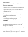
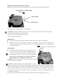
OPERATOR’S MANUAL AND PARTS LIST
PETROL LAWNMOWER - WER21HW
Spares & Support: 01793 333212
www.webblawnmowers.co.uk
Before use please read & understand this manual, paying particular attention to
the safety instructions.
193805002
15/01/2015
1
Thank you for choosing our Petrol Lawnmower.
To ensure that you get the best results from your Petrol Lawnmower please read all of these safety and
operating instructions carefully before using this product.
TABLE OF CONTENTS
Product Specifications…..........2
Safety Rules…………………..3
Assembly/Pre-Operation..........5
Operation……………………..9
Maintenance…………………11
Maintenance Schedule………13
Trouble shooting…………….13
Storage………………………14
Service………………………14
Parts Diagram…………….....15
Declaration of Conformity….18
Warranty…………………….19
Also Available………………21
Warranty Registration………22
PRODUCT SPECIFICATION
Model number
WER21HW high wheel self propelled type
Petrol engine
190CC
Engine speed
3000/min
Cutting width
530mm
Adjustable cutting height
10-70mm
Grass collection capacity
70L
Sound Pressure Level 83.6dB(A) K=3dB(A)
Guaranteed Sound Power Level 98dB(A) K=3dB(A)
Max. vibration value
4.873m/s2 K=1.5m/s2
Water Hose
Connection
Drive lever
Brake lever
Triangle Knob
Air flap
Grass collector
Starter handle
Oil dipstick
Exhaust muffler
Height adjustment
handle
Spark plug
Front bumper
Air filter
2
Before Use
a) Read the instructions carefully: Be familiar with the controls and the proper use of the
equipment.
b) Never allow children or people unfamiliar with these instructions to use the lawnmower. Local
regulations may restrict the age of the operator.
c) Never mow while people, especially children, or pets are nearby. During use be wary of people or
pets entering the mowing area and turn off the machine until they are at a safe distance.
d) Never tamper with safety devices. Check their proper operation regularly.
Preparation
a) While mowing, always wear substantial footwear and trousers. Do not operate the equipment
when barefoot or wearing open sandals.
b) Thoroughly inspect the area where the equipment is to be used and remove all objects which
could be thrown by the machine or damage the blade. Watch for holes, ruts, or bumps. Tall grass
can hide obstacles.
c) WARNING - Petrol is highly flammable.
- Store fuel in containers specifically designed for this purpose.
- Refuel outdoors only and do not smoke while refuelling.
- Add fuel before starting the engine. Never remove the cap of the fuel tank or add petrol while the
engine is running or when the engine is hot.
- If petrol is spilled, do not attempt to start the engine but move the machine away from the area of
spillage and avoid creating any source of ignition until the petrol vapours have dissipated.
- Replace all fuel tank and container caps securely.
d) Replace faulty silencers.
e) Before use, always visually inspect to see that the blades, blade bolts and cutter assembly are not
worn or damaged. Replace worn or damaged blades and bolts in sets to preserve balance.
f) Do not operate the machine while under the influence of alcohol or drugs.
g) Disengage the self-propel mechanism before starting the engine.
h) Always wear safety goggles or safety glasses with side shields when operating the mower.
Operation
a) Do not operate the engine in a confined space where dangerous carbon monoxide fumes can
collect.
b) Mow only in daylight or in good artificial light.
c) Avoid cutting wet grass, where possible.
d) Always be sure of your footing, especially on slopes or wet grass.
e) Walk, never run while mowing.
f) For wheeled rotary machines, mow across the face of slopes, never up and down.
g) Exercise extreme caution when changing direction on slopes.
h) Do not mow excessively steep slopes.
i) Use extreme caution when reversing or pulling the lawnmower towards you.
j) Stop the blade(s) if the lawnmower has to be tilted for transportation, when crossing surfaces
other than grass, and when transporting the lawnmower to and from the area to be mowed.
k) Never operate the lawnmower with defective guards, or without safety devices, for example
deflectors and/or grass catchers, in place.
l) Do not change the engine governor settings or over-speed the engine.
3
m) Disengage all blade and drive clutches before starting the engine.
n) Start the engine or switch on the motor carefully according to instructions and with feet well
away from the blade(s).
o) Do not tilt the lawnmower when starting the engine or switching on the motor.
p) Do not start the engine when standing in front of the discharge chute.
q) Do not put hands or feet near or under rotating parts. Keep clear of the discharge opening at all
times.
r) Never pick up or carry a lawnmower while the engine is running.
s) Stop the engine and disconnect the spark plug wire:
- before clearing blockages or unclogging the chute;
- before checking, cleaning or working on the lawnmower;
- after striking a foreign object, then inspect the lawnmower for damage and make repairs
before restarting and operating the lawnmower;
- if the lawnmower starts to vibrate abnormally (check immediately).
t) Stop the engine:
- Whenever you leave the lawnmower;
- Before refuelling.
u) Reduce the throttle setting during engine shutdown and, if the engine is provided with a shutoff
valve, turn the fuel off when you have finished mowing.
v) Shut the engine off and wait until and the blade comes to complete stop before removing the
grass catcher.
w) Keep in mind that the operator or user is responsible for accidents or hazards occurring to other
people or their property.
x) Do not trim near drop-offs, ditches or embankments. The operator could lose footing or balance.
y) Never attempt to make wheel height adjustments while the engine is running.
Maintenance and Storage
a) Keep all nuts, bolts and screws tight to ensure the equipment is in safe working condition.
b) Never store the equipment with petrol in the tank, especially inside a building where fumes can
reach an open flame or spark.
c) Allow the engine to cool before storing in any enclosure.
d) To reduce the risk of fire, keep the engine, silencer, battery compartment and petrol storage area
free of grass, leaves, or excessive grease.
e) Replace worn or damaged parts to ensure your machine runs safely and efficiently.
f) If the fuel tank has to be drained, this should be done outdoors.
g) Only use accessories approved by the manufacturer.
h) Keep the machine free of grass, leaves, or other debris build-up. Clean oil or fuel spillages. Allow
the machine to cool before storing.
i) Grass catcher components are subject to wear, damage, and deterioration, which could expose
moving parts or allow objects to be thrown. Frequently check components and replace with
manufacturer’s recommended parts, when necessary.
j) Mower blades are extremely sharp. Wrap the blade(s) or wear gloves, and use extra caution when
servicing them.
4
SYMBOLS
The following symbols can be found on the machine to remind you of the care and attention that are
required during use. The symbols mean:
DANGER – Rotating
Warning! Keep hands
Read the
blades. Keep hands
and feet clear of the
Operator’s
and feet out of
cutting deck when the
Manual.
openings while the
machine is running.
machine is running.
Warning! Before starting
Keep
Before you work on
any repair work, remove
bystanders
the cutting equipment,
the spark plug cable
clear.
remove the spark plug
from the spark plug.
socket.
Warning! Keep other persons
Remove Objects that could
at a safe distance when
Be thrown by the blade.
using this lawnmower.
IMPORTANT: This machine is capable of cutting off hands and feet or throwing objects. Failure to
observe the following safety instructions could result in serious injury or death.
WARNING: In order to prevent accidental starting when setting up, transporting, adjusting or making
repairs, always disconnect the spark plug wire.
WARNING: Engine exhaust, some of its constituents, and certain vehicle components contain or emit
chemicals known to cause cancer and birth defects or other reproductive harm.
CAUTION: Exhaust and other engine parts become extremely hot during operation and remain hot after
the engine has stopped. To avoid severe burns on contact, stay away from these areas.
ASSEMBLY/PRE-OPERATION
Read this manual in its entirety before you attempt to assemble or operate your new lawnmower.
IMPORTANT: The lawn mower is shipped WITHOUT OIL OR PETROL in the engine. Your new
lawn mower has been assembled and tested at the factory.
REMOVE LAWN MOWER FROM CARTON
Roll lawn mower out of carton and check carton thoroughly for additional loose parts.
5
INSTALL ATTACHMENTS
Please note your lawn mower may have been shipped with the mulching plug already fitted under the rear
grassbox flap.
The mower has four different operating modes.
1. Collecting:
• Ensure that the side cover is closed.
• Fit the grassbox by lifting the rear flap on the mower and hook the front of the box to the shaft on the
mower.
• Lower the flap to lock the grassbox in position.
• When the box is full, the grass will be visible through the viewing window in the top of the box.
• Stop the engine before emptying the grassbox.
2. Rear Discharge:
• Ensure that the side cover is closed.
• With the grassbox removed and the rear flap in the down position, the mower will cut and discharge the
grass from the rear of the machine.
3. Side Discharge:
• Fit the mulch plug to the rear discharge opening of the mower and close the rear flap.
• Lift the cover on the side of the mower and attach the side discharge chute as shown in the diagram.
• The mower will now eject grass from the side discharge chute.
4. Mulching:
• Fit the mulch plug to the rear discharge opening of the mower and close the rear flap.
• Ensure that the side cover is in the closed position (with the discharge chute removed).
• The mower will now recycle the chopped grass into the lawn surface.
• To mulch efficiently only cut one third of the length of the grass.
ASSEMBLE HANDLE
Fit the Lower Handle to the frame of the lawnmower.
Insert 1x Square Neck Bolt M8x30 into the lower hole of the handle and frame from the outside.
Once through, add the Flat Washer and Small Triangle Knob with M8 Hex Nut, tighten until they are
secure.
Insert a Hex Bolt M8x16 into the second lower handle fixing and frame hole from the outside.
Once through, add a Lock Nut M8/8.8 and tighten.
Fit the Upper Handle to the Lower Handle.
There are two holes in the Upper Handle, insert the Carriage Bolt M8x50 from the inside through the
Lower Handle and your selected hole in the Upper Handle to assemble the handle at your chosen height.
Once through, fit a Flat Washer and Large Triangle Knob with an M8 Hex Nut, tighten until they are
secure.
To avoid damage during the transport process, the drive and brake cables for your machine may not be
fitted to their appropriate handle bar.
The front cable is the brake cable, which is to be fitted to the front lever on your machine, this is the
Operator Presence Control Lever (OPC). The cable at the rear is your drive cable, which is to be fitted to
the rear lever, which is your Drive Lever.
6
7
8
OPERATION
Drive lever
Push handle
Operator Presence
Control Bar
Brake lever - must be held down to the handle to start the engine. Release to stop the engine.
Starter handle - used for starting the engine.
Drive control lever - used to engage the self-propel system.
USE YOUR LAWNMOWER ENGINE SPEED
The engine speed was set at the factory for optimum performance. Speed is not adjustable.
DRIVE CONTROL
z Self-propelling is controlled by holding the operator presence control bar down to the handle and
pushing the drive control lever forward until it clicks; then releasing the lever.
z Forward motion will stop when the operator presence control bar is released.
To stop forward motion without stopping the engine release the operator presence control bar slightly until
the drive control disengages. Hold the operator presence control bar down against handle to continue
mowing without self-propelling.
ADJUST CUTTING HEIGHT
Raise wheels for the highest cut and lower wheels for a lower cut; adjust cutting height to suit your
requirements. Medium position is best for most lawns.
9
BEFORE STARTING THE ENGINE ADD OIL
Before each use the oil level must be checked and if necessary topped up with SAE30 engine oil.
OIL FILLER CAP/DIPSTICK
UPPER LIMIT
LOWER LIMIT
Your lawnmower is shipped without oil in the engine.
CAUTION: DO NOT overfill the engine with oil, or it will smoke heavily from the exhaust on startup.
1. Be sure the lawnmower is on a level surface.
2. Remove the oil dipstick from the oil fill spout.
3. Insert and tighten the dipstick.
IMPORTANT:
z Check the oil level before each use. Add oil if needed. Fill to the full line on the dipstick.
z Change the oil after every 25 hours of operation or each season. You may need to change the oil
more often under dusty, dirty conditions. See “TO CHANGE ENGINE OIL” in the Maintenance
section of this manual.
FUEL TANK CAP
ADD PETROL
z Fill the fuel tank to the bottom of the tank filler neck. Do
not overfill. Use fresh, clean, regular unleaded petrol. Do
not mix oil with petrol. Purchase fuel in quantities that can
be used within 30 days to ensure fuel freshness. Old or
stale fuel can cause damage to the engine carburettor
which would not be covered under the warranty.
CAUTION: Wipe off any spilled oil or fuel. Do not store, spill
or use petrol near an open flame.
CAUTION: Alcohol blended fuels (called gasohol or using
ethanol or methane can attract moisture which leads to separation and formation of acids during storage.
Acidic gas can damage the fuel system of an engine while in storage. To avoid engine problems, the fuel
system should be emptied before storage of 30 days or longer. Empty the gas tank, start the engine and let
it run until the fuel lines and carburettor are empty. Use fresh fuel next season. See Storage Instructions
for additional information.
Never use engine or carburettor cleaner products in the fuel tank, permanent damage may occur.
10
START THE ENGINE
To start the engine, first check that the spark plug is tightened and that the machine is filled with sufficient
oil and petrol.
NOTE: Due to the protective coating on the engine, a small amount of smoke may be present during the
first use of the product and should be considered normal.
Hold the operator presence control bar down to the handle and pull starter handle quickly.
Hold the starter handle as the rope retracts back into the mower do not allow the rope to snap back.
STOP THE ENGINE
z To stop the engine, release the operator presence control bar.
WARNING! The blade may continue to rotate for a few seconds after the engine has stopped.
Disconnect the spark plug cap if the lawnmower is to be left unattended.
MOWING TIPS
z Under certain conditions, such as very tall grass, it may be necessary to raise the height of cut to
reduce pushing effort and to keep from overloading the engine and leaving clumps of grass clippings.
It may also be necessary to reduce ground speed and/or run the lawnmower over the area a second
time.
z For extremely heavy cutting, reduce the width of cut by overlapping the previously cut path and mow
slowly.
z Pores in cloth grass catchers can become filled with dirt and dust with use and catchers will collect
less grass. To prevent this, regularly hose the catcher off with water and let it dry before use.
z Keep the top of engine around the starter clean and clear of grass clippings and chaff. This will help
engine air flow and extend engine life.
MAINTENANCE
IMPORTANT - Regular, careful maintenance will extend the lifespan of your machine and ensure
that it runs efficiently and safely.
1) Keep all nuts, bolts and screws tight to be sure the equipment is in safe working condition.
Regular maintenance is essential for safety and performance.
2) Never store the equipment with fuel in the tank inside a building where vapours may reach a flame,
spark or a source of heat.
3) Allow the engine to cool before storing in an enclosed space.
4) To reduce the fire hazard, keep the engine, exhaust silencer, battery compartment and fuel storage area
free of grass, leaves, or excessive grease. Do not store containers full of grass cuttings.
5) For safety reasons, do not use the equipment with worn or damaged parts. Parts are to be replaced not
repaired. Use genuine spare parts (blades should always bear the symbol).
Parts that are not of the same quality can damage the equipment and be dangerous for your safety.
6) If the fuel tank has to be drained, this should be done outdoors and when the engine is cool.
7) Wear strong work gloves when removing and reassembling the blade.
8) Check the blade’s balance after sharpening.
9) Check the self-closing guard and grass-catcher frequently for wear and deterioration.
10) Whenever the machine is to be handled, transported or tilted you must:
- Wear strong working gloves;
- Grasp the machine at the points that offer a safe grip, clear of the blade and taking account of the weight
of the machine and its distribution.
11
CLEANING
Carefully clean the machine with water after each cut; remove the grass debris and mud accumulated
inside the chassis to avoid their drying and thus making the next start-up difficult.
The paintwork on the inside of the chassis may peel off in time due to the abrasive action of the cut grass;
in this case, intervene promptly by touching up the paintwork using a rustproof paint to prevent the
formation of rust that would lead to corrosion of the metal.
Remove the transmission casing by removing the screws and clean around the transmission and drive
belts with a brush or compressed air once or twice a year.
Once every season, the drive wheels should be cleaned internally. Remove both wheels. Clean the gear
wheel and the wheel gear rim of grass and dirt using a brush or compressed air.
CHANGING BLADES
Empty the oil tank before removing the blade.
To replace the blade, undo the screw.
Reinstall as illustrated. Tighten the screw properly. Tightening torque 45 Nm.
When replacing the blade, the blade screw should also be replaced.
ENGINE MANUAL
You should refer to your engine manual for instructions on changing the engine oil, air filter and draining
the fuel tank and carburettor.
Warning: Avoid skin contact with used engine oil. Wash your skin with soap and water after changing the
oil.
Caution: Used oil is a hazardous waste product. It is recommended that used oil is taken to your local
recycling centre in a properly sealed container. Do not discard with household waste.
Spark Plug
Once the engine has cooled, remove the spark plug and clean the plug with a wire brush. Using a feeler
gauge, set the gap to 0.75 mm (0.030”). Refit the spark plug taking care not to overtighten it.
12
MAINTENANCE SCHEDULE
REGULAR SERVICE PERIOD
ITEM
Perform at every indicated month or operating
hour interval, whichever comes first.
Engine oil
Before
Each
Use
First
Month
or
5 Hrs
Every 3
Months
or
25 Hrs
Every 6
Months
or
50 Hrs
Every
Year
or
100 Hrs
Every Two
Years
or 250 Hrs
Check
Engine
Manual
Replace
Air cleaner
Check
Engine
Manual
Replace
Spark plug
Page
Check-adjust
13
Replace
Flywheel brake pad (A types)
Check
Fuel tank and filter
Clean
Fuel tube
Check
Valve clearance
Check-adjust
Combustion chamber
Clean
Every 2 years (Replace if necessary)
Engine
manual
After every 200 hours
-
TROUBLE SHOOTING
ENGINE WILL NOT START
Possible Cause
Correction
1. Check fuel.
Out of fuel.
Refuel.
Bad fuel: engine stored without draining
petrol, or refuelled with bad petrol
Drain the fuel tank and carburettor
(p.14). Refuel with fresh petrol.
Spark plug faulty, fouled, or improperly
gapped.
Replace the spark plug (p.13).
Spark plug wet with fuel (flooded engine).
Dry and reinstall spark plug.
Fuel filter clogged, carburettor malfunction,
ignition malfunction, valves stuck, etc.
Replace or repair faulty components
as necessary.
2. Remove and inspect the spark
plug.
3. Take the engine to an
authorised service dealer, or refer
to the engine manual.
ENGINE LACKS POWER
Possible Cause
Correction
1.Check the air cleaner
Air cleaner elements clogged.
Clean or replace air cleaner elements (p.13).
2. Check the fuel
Bad fuel; engine stored without draining
petrol, or refuelled with bad petrol.
Drain the fuel tank and carburettor (p.14).
Refuel with fresh petrol.
3. Take the engine to an
authorised service dealer, or
refer to the engine manual.
Fuel filter clogged, carburettor
malfunction, ignition malfunction, valves
stuck, etc.
Replace or repair faulty components as
necessary.
13
Tune up Specifications
ITEM
SPECIFICATION
MAINTENANCE
Spark plug gap
0.028-0.031in (0.7-0.8 mm)
Refer to page 13.
Valve clearance (cold)
IN:0.06±0.02mm
EX;0.08±0.02mm
See your authorised dealer
Other specifications
No other adjustments needed.
STORAGE
The same petrol must not remain in the tank for more than 30 days.
Thoroughly clean the mower and store it in a dry place.
THE ENVIRONMENT
In order to protect the environment, we recommend that the following points should be given special
consideration:
z Always use pure unleaded petrol.
z Always use a funnel and/or a petrol can with a level control to avoid spillage when refilling the fuel
tank.
z Do not fill the fuel tank completely.
z Do not overfill with engine oil.
z When changing the oil, ensure that all the used oil is collected. Avoid spillage .Take used oil to a
recycling unit.
z Do not dispose of a used oil filter in a rubbish bin. Take it to a recycling unit.
z Replace the silencer if faulty. When carrying out repairs, always use original spare parts.
z Always seek professional help when the carburettor requires adjustment.
z Clean the air filter according to directions.
SERVICING
Genuine spare parts are supplied by service workshops and by many dealers. We recommend that
you take the machine to an authorised service dealer for annual servicing, maintenance and
inspection of the safety equipment. For service and spare parts, please contact:
Tel: 01793 333212
Fax 01793 729988
[email protected]
[email protected]
www.handyspares.co.uk
14
Parts Diagram
15
Parts List
REF PART NO
DESCRIPTION
QTY REF PART NO
DESCRIPTION
QTY
1
WE104-1
Foam Handle Cover
1
39
WE104-39
Drive V Belt
1
2
WE104-2
Upper Handle
1
40
WE104-40
B&S 675 Engine
1
3
WE104-3
Brake Lever
1
41
WE104-41
Rear Discharge Cover Spring
1
4
WE104-4
Drive Lever
1
42
WE104-42
Rear Discharge Cover
1
5
WE104-5
Hex Flange Bolt M6x30/8.8
1
43
WE104-43
Rear Discharge Cover Shaft
1
6
WE104-98
Cable Bracket
1
44
WE104-44
Side Discharge Chute
1
7
WE104-7
Hex Nut M8/8.8
4
45
WE104-45
Side Discharge Cover
1
8
WE104-101
Hex Nut M6/8.8
1
46
WE104-107
Side Discharge Spring
1
9
WE104-9
Cap Nut M6/8.8
1
47
WE104-47
side Discharge Bracket
1
10
WE104-10
Right Front Axle Bracket
1
48
WE104-48
Lock Nut M5/8.8
4
11
WE104-11
Flange Face Lock nut M6
3
49
WE104-49
Side Discharge Shaft
1
12
WE104-102
Crankshaft Key 20mm
1
50
WE104-50
Hex Bolt M5x10/8.8
2
13
WE104-13
Short Washer for Blade Adapter
1
51
WE104-51
Height Adjustment Handle
1
14
WE113-5
Rope Guide
1
52
WE104-52
Right Bracket
1
15
WE113-21
Fastener
1
53
WE104-53
Rear Drive Right Plate
1
16
WE104-16
Carriage Bolt M8X32
2
54
WE113-25
"O" Ring 11.2x2.65
1
17
WE104-103
Bolt M8X45
4
55
WE113-26
Hose Connector Inlet
1
18
WE104-104
Self-Tapping Screw ST6.3x30
1
56
WE113-27
Hose Connector Nut M12x1.25
1
19
WE104-19
Plug
2
57
WE113-28
Cable Stopper
1
20
WE104-20
F type lower handrail
1
58
WE104-58
Deck
1
21
WE104-21
Flat Washer 8.4x16x1.6
6
59
WE104-59
Hex Self-Tapping Screw 3/8-16x1ST
3
22
WE113-74
Triangle knob
4
60
WE104-60
Hex Bolt M5x30/8.8
2
23
WE104-23
Mulching Plug
1
61
WE104-61
Rear Discharge Cover Pedestal
1
24
WE104-24
Rear Baffle
1
62
WE104-62
Front Deck Cover
1
25
WE104-25
Dustproof Pedestal
1
63
WE104-63
Back Board Pedestal
1
26
WE104-26
Dustproof Board
1
64
WE104-64
Hex Lock Nut M8
14
27
WE104-105
11" Wheel Trim (Grey)
2
65
WE104-65
Self-Propelled Axle Sleeve
2
28
WE104-28
Lock Nut M8/8.8
4
66
WE104-66
Rear Axle
1
29
WE104-106
11" Wheel
2
67
WE104-67
Small Washer 13x20x1.5
6
30
WE104-30
Bearing R8-2RS 12.65x28.6x8
8
68
WE104-68
W Spring Pin
1
31
WE104-31
11" Inner Wheel Cover
2
69
WE104-69
Right Bracket
1
32
WE104-32
Flexible Washer 12
6
70
WE104-70
Carriage Bolt M8x16/8.9
8
33
WE104-33
Ratchet Washer
4
71
WE104-71
Rear Drive Left Plate
1
34
WE104-34
Drive Cog Left
1
72
WE104-72
Self-Tapping Screw ST6.3*14
8
35
WE104-35
Drive Pin
6
73
WE104-73
Height Adjustment Pull Rod
1
36
WE104-37
1
74
WE113-38
Height Adjustment Spring
1
37
WE104-36
Transmission
1
75
WE104-75
Belt Cover Bracket Left
1
38
WE104-38
Drive Cog Right
1
76
WE104-76
Belt Cover
1
Self-Propelled
Spring
16
REF PART NO
DESCRIPTION
QTY REF PART NO
DESCRIPTION
QTY
77
WE104-77
Belt Cover Bracket Right
1
89
WE104-109
8" Wheel
2
78
WE104-78
Bag Cover Ventilation
1
90
WE104-90
8" Inner Wheel Cover
2
79
WE104-79
Handle Cap
1
91
WE104-91
Carriage Bolt M8x25/8.8
2
80
WE104-80
Grass Collector Top
1
92
WE104-92
Front Bumper
1
81
WE104-81
Grass Collector Frame
1
93
WE104-93
Front Axle
1
82
WE104-82
70L Grass Collector Bag (Unbranded)
1
94
WE104-94
Carriage Bolt M6X12
2
83
WE113-71
Hex Flange Bolt 50mm
1
95
WE104-95
Left Front Axle Bracket
1
84
WE113-70
Blade Washer
1
96
WE104-96
Self-Tapping Screw ST4.2x14
7
85
WE104-85
21" Blade
1
97
WE104-97
Carriage Bolt M8x30
2
86
WE104-86
Blade Adaptor
1
98
WE104-110
Circlip
1
87
WE104-87
Engine Pulley
1
99
WE104-99
88
WE104-108
8" Wheel Trim (Grey)
2
100
WE104-100
17
Brake
Cable
Self-Propelled Cable
1
1
EC Declaration of Conformity
We, Importer
Handy Distribution
SN3 5HY
Declare that the product
Model: WER21HW
Complies with the following directives:
2006/42/EC- Machinery Directive
2004/108/EC- Electromagnetic Compatibility Directive
2000/14/EC amended by 2005/88/EC- Noise Emission in the Environment by Equipment for
Use Outdoors Directive.
The conformity assessment procedure followed was in accordance with
Directive 2006/42/EC Annex VI
Name of the Notified Body: TÜV Rheinland LGA Products GmbH
Address:. Tillystrasse 2, 90431 Nurnberg, GERMANY
-Measured Sound Pressure Level: 96.2 dB (A)
-Guaranteed Sound Power Level: 98 dB (A)
Standards and technical specifications referred to:
EN 836/A3:2004
ZEK01.2-08.2008
EN ISO 14982:2009
EN ISO 3744:1995
ISO 11094:1991
Authorised signatory and technical file holder
Date: 28/3/2012
Signature:
Name / title: Mr. Simon Belcher / Managing Director
Murdock Rd, Swindon, Wiltshire, SN3 5HY.
18
GJ HANDY & CO LTD USER WARRANTY POLICY
1. Users Statement of Warranty
Each new machine is warranted against defective material or assembly of material under normal usage. The
warranty applies to the original purchaser and covers faulty parts and the labour involved in replacing and
repairing those parts, which are of original manufacture.
2. Period of Warranty
All Webb, Handy Pro (Brushcutter & Long Handle Hedgecutter only) and Sanli domestic products
(a)
2 years from the original date of sale to the first domestic user.
(b)
90 days from the original date of sale to the professional/commercial user.
(c)
90 days from the original date of sale when used for hire.
(d)
Engines as per the manufacturer’s warranty statement which will be supplied with the machine.
(e)
90 days from the original date of purchase for Replacement Spare Parts.
(f)
All machines must be serviced within the first 12 months from the original date of purchase to comply
with the warranty, failure to do so will invalidate the second year of the warranty.
(g)
A reduced warranty period of 90 days applies to those items which are subject to normal wear and tear
(e.g. wheels, tyres, cutter bars, cylinders, bottom blades, belts, cables, grass bags, spark plugs).
All Handy, Handy Pro (All others), Mowerland and Q-Garden domestic products
(a)
1 year from the original date of sale to the first domestic user.
(b)
90 days from the original date of sale to the professional/commercial user.
(c)
90 days from the original date of sale when used for hire.
(d)
Engines as per the manufacturer’s warranty statement which will be supplied with the machine.
(e)
90 days from the original date of purchase for Replacement Spare Parts.
(f)
A reduced warranty period of 90 days applies to those items which are subject to normal wear and tear
(e.g. wheels, tyres, cutter bars, cylinders, bottom blades, belts, cables, grass bags, spark plugs).
All warranty repairs must be undertaken by an authorised service dealer. These dealers have been accredited
by GJ Handy & Co Ltd and agree to only use genuine parts and follow our repair procedures.
GJ Handy & Co Ltd reserve the right to change specifications and/or price without notice
Version 2 08-2014
19
GJ HANDY & CO LTD USER WARRANTY POLICY
3. Not covered by this warranty
(a)
The warranty policy does not cover any depreciation or damages caused by ordinary wear, rusting or
corrosion, lack of correct maintenance or operation, misuse, abuse, lack of transportation or accident.
(b)
The warranty policy does not cover any costs necessary for the standard periodic maintenance services
instructed by the operators manual, or service parts replacement which would include oil, filters, tyres,
belts, brake linings, fuses, blades, seals and other service parts unless it can be proven that the item has
evidence of faulty manufacture.
(c)
The warranty policy will not cover failure or damage caused as a result of parts or accessories being
modified without the written approval of GJ Handy & Co Ltd.
(d)
The warranty policy will not cover the unit if non-genuine parts have been fitted and as a result the unit
has been damaged.
(e)
The warranty policy is non-transferable and is only applicable to the original purchaser.
4. Disclaimer
(a)
This warranty is only a remedy for product defects. GJ Handy & Co Ltd will never issue a warranty for the
merchantability of a product or its fitness for a particular purpose.
(b)
No person is authorised to make any warranties, representations or promises, expressed or implied, on
behalf of GJ Handy & Co Ltd, or to modify the terms conditions or limitation of this warranty policy in any
way.
(c)
Neither GJ Handy & Co Ltd nor any company affiliated with GJ Handy & Co Ltd shall be liable in any
event or manner whatsoever for incidental or consequential damages or injuries, including, but not
limited to, loss of crops, loss of profit, out of pocket expenses or profits, rental of substitute equipment or
other commercial losses.
5. General
(a)
Most warrantable failures show up within the first few weeks of use. These failures are usually
straightforward and warranty assessment is relatively easy.
(b)
Failures relating to cutter decks and belts need careful investigation, as the cause may not always be
straightforward. Look for damage to blades and pulleys especially when the cutter belt or blade boss
have snapped or cracked as this could be due to impact damage.
(c)
Customers should always refer to the operator’s instruction manual when any disputed problem arises,
you will find most areas covered within the manual.
GJ Handy & Co Ltd reserve the right to change specifications and/or price without notice
Version 2 08-2014
20
A SELECTION OF QUALITY PRODUCTS FROM OUR VAST RANGE
• HAND PUSH CYLINDER
LAWN MOWERS
• ELECTRIC & PETROL
CYLINDER
LAWN MOWERS
• INTERCHANGEABLE
CYLINDER CARTRIDGES
• ELECTRIC & PETROL ROTARY
LAWN MOWERS
• PETROL RIDE ON
LAWN MOWER
• PETROL LAWN SCARIFIER
FIND OUT MORE AT WWW.WEBBLAWNMOWERS.CO.UK
21
Date of Delivery: .........................................
(Warranty Commences From Date of Delivery)
Engine No:…….....................................................
Serial No: ....................................... .............
Date of Purchase: .........................................
Model: ..................................................................
Product: .......................................................
Agent/ Dealer: ……………………........................................
Email Address: ……………………......................................
…………………………… Postcode:………………….. Telephone No.: ……..……………................
Address: ……………………………………………………………………………………….........................
Owner’s Name: …………………..…………………………………………………………………..................
Please go to www.webblawnmowers.co.uk select registration and complete the registration for your machine.
(Alternatively please fill in this form and return to the address above.)
Warranty Registration Form
Webb Lawnmowers,
Hobley Drive,
Swindon,
SN3 4NS, United Kingdom.
Telephone: +44 (0) 1793 333220
Fax: +44 (0) 1793 834461
E-mail: [email protected]
www.webblawnmowers.co.uk
Webb Lawnmowers
Hobley Drive
Stratton St Margaret
Swindon
Wiltshire
SN3 4NS