1
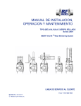
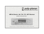
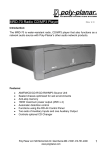
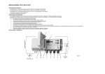
RD-44 Audio Network Control Panel
Introduction:
The RD-44 is designed to control the audio functions and sources of the
MRD-70 marine radio and the MZ-100 DSP Zone Amplifier. With
versatile mounting options, the RD-44 can be installed up to 60 feet
away from the radio or amplifier in a variety of positions. In addition, the
built-in intercom function allows communication between the vessel’s
audio zones.
Features:
Full control of audio functions and sources
32 character back-lit digital display
Self-dimming for night time use
Back-lit keypad
Waterproof, corrosion resistant enclosure
Dash or bracket mount options
Built-in Intercom
Infrared remote control
1352 Charwood Road • Suite D • Hanover, MD 21076 • Tel (410) 761-4000
www.polyplanar.com
1
Controls
1
2
3
4
5
7
6
8
10
9
11
12
13
17
16
14
15
1 Microphone
9 Volume Control
2 Intercom Switch
10 Auto Station Set
3 Presets
11 Audio Controls
4 Set Display
12 Radio Source Select
5 Tune/Track Up
13 Power On/Off
6 Tune/Track Down
14 Mute
7 AM/FM Band
15 Amplifier Source Select
8 Scan Channels
16 Network Cable
17 Infrared Port, Ambient
light sensor
2
1352 Charwood Road • Suite D • Hanover, MD 21076 • Tel (410) 761-4000
www.polyplanar.com
Control Functions
1 Microphone: Waterproof intercom microphone.
2
Intercom Switch: Hold down to talk. Release to hear. The intercom
will override the music in the other zones. It will also disable a muted
RD-44 in another zone while the switch is pressed.
The volume for each zone with an RD-44 is adjustable. While holding
the “Mic” button (# 2) down , use the Volume knob (9) to toggle the
intercom volume up or down. (See Volume, # 9). The Master zone
intercom volume is set using a potentiometer on the RT-20 Router (See
RT-20 Instructions)
3
Presets: Tune to a desired AM, FM 1, FM2 or XM (optional) station and
hold the desired preset button for at least 2 seconds. The display will
change to show which preset was programmed.
4
Display: Allows setting of display modes. Times out after 2 seconds.
Displays available information from WMA, MP3 or XM formats. Pressing
the button advances the display functions.
In CD Mode: x1 = Artist x2 = Album x3 = Folder x4 Track /Time
In XM Mode: x1 = Artist x2 = Song x3 = Category
5
Up: Tunes Radio frequencies or changes tracks higher.
6
Down: Tunes Radio frequencies and changes tracks lower.
7
Band Select: Choose between AM 1, AM 2 and FM 1, FM2, FM 3
station banks.
8
Scan: AM/FM mode. Tunes and stops at available stations for a few
seconds. Press scan a second time or one of the tune buttons to stop
scanning.
9
Volume: Adjusts volume by toggling the knob right or left. Turn to the
left and hold to decrease volume or right and hold to increase volume.
This knob is self-centering.
10 Auto Station Set: Scans for strong stations and stops. Pressing the
button again will select the next station up. The receiver will scroll up
the frequency scale and begin again at the bottom.
1352 Charwood Road • Suite D • Hanover, MD 21076 • Tel (410) 761-4000
www.polyplanar.com
3
11 Audio Controls: Pressing this button will cycle through the audio
functions of the radio. Use the Volume knob (9) to adjust the function up
, down or “C” center. The functions vary slightly between the MRD-70
and MZ100. After waiting 3 seconds, the radio will exit the menu.
MRD-70:
Bass:
Bass can be adjusted up to +/- 12.
Treble: Treble can be adjusted up to +/- 12.
Balance: (Left and Right) Adjustable up to +/- 15.
Fader: (Front and Back) Adjustable up to +/- 15.
Loud: Dynamically adjusts bass level to Volume when ON
MZ-100 Amplifier:
Bass: Bass can be adjusted up to +/- 12.
Treble: Treble can be adjusted up to +/- 12.
Space: Adjust to 0, 1, or 2. This unique feature adds a function in
the audio that simulates wider spacing on the speakers. Press 3
times to exit function
Loud: Turns on /off dynamic loudness (Bass enhancement)
EQ: Turns on/off Selected EQ (See MZ100 instructions)
12 Source: Selects a source from those available on the MRD-70 radio
such as AM 1-2 FM 1-2-3 CD/MP3, AUX1, AUX2 and XM, if installed.
13 Power: Powers on and off the RD44 display, MRD-70, MZ amplifiers
and its peripherals.
14 Mute: Mutes the audio in the local zone.
15 Zone Amplifier Source: Source select for the MZ series amplifiers.
Not used with the MRD-70.
16 Network Cable: Connects RD44,RT20, and MZ100 components
17
4
Infrared Port & Light Sensor: Receiver for MRR2 Remote and
senses ambient light and automatically adjusts backlighting.
1352 Charwood Road • Suite D • Hanover, MD 21076 • Tel (410) 761-4000
www.polyplanar.com
Panel Mounting
(Network connection cable not shown for clarity)
Break off as needed
The RD44 can be mounted in a
panel using the supplied “U” bracket and stainless steel stud assembly.
Insert the supplied stud into the threaded rear housing. Use one of the
5mm nuts to lock the stud in place.
Find a suitable location with enough depth and access for the DIN
network connecting cable and hand access to tighten the nut.
Use the template provided to drill 2 holes: 2⅛ (54mm) for the main body
and 3/16 (5mm) for the locating pin. Insert the RD44 and use the bracket
and nut to secure the Display. Do not over tighten the nut.
The “U” bracket has break off sections that can be removed for thick
panels.
Bracket Mount
The RD-44 can also be mounted using the supplied back cover and
bracket. The bracket can be installed for dash or overhead mount.
Make sure that there is adequate clearance and a good viewing angle
for the display. Also, consider the routing of the network cable.
Use the bracket to mark the position of the fastener holes.
1352 Charwood Road • Suite D • Hanover, MD 21076 • Tel (410) 761-4000
www.polyplanar.com
5
Bracket Mounting
cont.
Dash Mount
Overhead mount
Bracket
Screw
Captured nut detail
Installing the Back Cover
A short (10mm) M5 screw holds the back panel assembly to the body
of the RD-44. Remove the back panel and insert the 8mm hex nuts
supplied into the retaining slots as shown above in the detail. .
Use the 8mm screws and the cover plate provided to attach the
bracket to the rear housing. The rear housing can be rotated 180° for
dash or overhead mounting.
Use the 5mm short screw to attach the rear housing to the RD-44
body.
6
1352 Charwood Road • Suite D • Hanover, MD 21076 • Tel (410) 761-4000
www.polyplanar.com
Connecting the System DIN
Cable
The RD-44 connects to the system using a single cable with watertight
ends available in 10ft (3m), 20Ft (6m) and 60ft (18m) lengths. These
cables can be used in any combination to provide the needed
connection length.
The DIN cable is “Keyed” to prevent
misalignment and all connections are
gender specific
Leave the end caps on when routing to
prevent damage or contamination to the
leads. The cap is designed for pulling
through wire conduits.
(Connector cap ends removed)
The blue connector cap ends can be
discarded if a smaller diameter is
required such as a Pod mount. Use
shrink tube to seal the connections.
Before drilling holes for cable runs be sure there is sufficient room behind the
area. Always disconnect power before drilling around electrical connections.
The hole diameter requirements:
Without = ½” (13mm) Ø
With ends = 7/8” (22mm) Ø
Be sure to use Grommets or other types of chafe protection when routing
cables through fiberglass or metal bulkheads or instrument pods.
Provide strain relief by securing
cables with proper cable ties
System Connections
The
RD44
can
be
used
in
several
1352 Charwood Road • Suite D • Hanover, MD 21076 • Tel (410) 761-4000
www.polyplanar.com
7
configurations:
Basic MRD70 System, Single Zone
Multi Zone System using RT-20 Router (See RT-20, MRD70 Instruction Manual)
8
1352 Charwood Road • Suite D • Hanover, MD 21076 • Tel (410) 761-4000
www.polyplanar.com
System Connections
(continued)
Single Zone with MZ-100 DSP AMP
The MZ-100 can be controlled by the RD-44 control panel. Using an ICC
10, 20 or 60 DIN extension cable (not shown) the panel can be up to 60
feet away from the amplifier. Plug the RD-44 or its extension cable into
the CONTROL PANEL plug on the MZ-100. Be sure to tighten the
waterproof connectors.
The MZ-100 can support 1 Auxiliary input such as iPOD dock or other
media player. (See MZ-100 instruction Manual)
MRR2 Wireless Remote Control
The Poly Planar MRR2 Wireless Remote can be
used with the RD44 Display. Simply point the
Remote at the Display and you can activate the
primary functions. The MRR2 requires “Line of
site” to the IR window of the Display and will
operate up to 30 ft away.
1352 Charwood Road • Suite D • Hanover, MD 21076 • Tel (410) 761-4000
www.polyplanar.com
9
Specifications:
Operating Voltage ………………….. ……… 13.8V (10V – 16V) DC
Dimensions …………………………………. 4.409” x 4.409” x 1.443”
(112mm x 112mm x 37mm )
Immersion Protection………………………………………...Min. IP65
Weight ……………………………………….. ………15 oz (.425 Kg)
WARRANTY
Poly-Planar marine audio systems are warranted to be free of defects in
materials and workmanship for a period of two years. Warranty is subject
to proper installation and operation within published specifications. PolyPlanar will repair or replace, at its discretion, any unit returned prepaid to
its factory and determined to be defective. Poly-Planar Inc. is not liable
for consequential damages.
10
1352 Charwood Road • Suite D • Hanover, MD 21076 • Tel (410) 761-4000
www.polyplanar.com