1
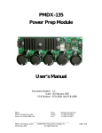
poly-planar
MRR-7 Keypad - IMR-2 Interface
1
————————————————————————————
Maryland USA (410) 761-4000 -
www.polyplanar.com
Waterproof Marine Audio
poly-planar
MRR-7 Keypad - IMR-2 Interface
2
————————————————————————————
Maryland USA (410) 761-4000 -
www.polyplanar.com
Waterproof Marine Audio
MRR-7 Wired Remote Keypad with Intercom
+
poly-planar
IMR-2 Remote Interface Module
[1]
Mic
Volume
[2]
-
INTERCOM
Introduction:
The MRR-7 Wired Remote Keypad / Intercom are designed to interface to the
Audio Expansion Port™ of the Poly-Planar line of Audio Center via the IMR-2
Interface Module. The MRR-7 will fit in a standard 2-1/8” instrument gauge
hole and can be mounted either above or below deck. The back-lit silicone
rubber keypad can control all the major functions of the Audio Center, and the
integrated microphone allows for clear communication between zones.
[7]
MIC
[3]
[4]
[16]
[17]
[14]
TUNE
VOLUME
SOURCE
[8]
Volume Mode Switch
Zone Amp
Radio
[5]
[6]
DISC +
[9]
[10]
[11]
BAND
AUTO
MUTE
[12]
[13]
POWER
[15]
MRR-7 Remote Keypad / Intercom features
•
•
•
•
•
•
•
•
•
Waterproof design for inside or outside mounting
Backlight key illumination
Small size and easy to mount
Available in white or black color
Can be used up to 60 feet from Audio Center with optional extension
cables
Integrated microphone for use as intercom between boat helm and
cabin or between different zones
Control of Audio Center from remote location
Can be configured to control volume in separate amplified zone
Built-in IR Sensor allows use with MRR-1 IR Remote control
IMR-2 Keypad Interface Module Features
•
•
Allow for interface of 2 Remote Keypads or Microphones (up to 4 with
optional ‘Y’ cables)
Supports Intercom with expanded separate zone amplifier.
(Figure 1) front & rear view of MRR-7
MRR-7 KEYPAD BUTTONS AND FUNCTIONS
Refer to Audio Center instruction manual for details on control functions.
[1] [2] [3] [4] [5] [6] [7] [8] [9] [10] [11] [12] [13] -
Opening for the microphone
[14] – M5 Mounting stud
Intercom enable button
[15] – MiniDin cable 8 pin
Volume UP (increase)
[16] – Microphone volume control
Volume DOWN (decrease)
[17] – Volume control mode switch
Tune/seek UP (CD next trk)
Tune/seek DOWN (CD prev trk)
Source select
Next Disc (CD Changer mode)
Band (radio tuner FM 1,2,3 AM 1,2)
Mute
Auto set station / memory preset scan
Power on/off
Sensor for IR remote control
poly-planar
MRR-7 Keypad - IMR-2 Interface
3
————————————————————————————
Maryland USA (410) 761-4000 -
www.polyplanar.com
Waterproof Marine Audio
poly-planar
MRR-7 Keypad - IMR-2 Interface
4
————————————————————————————
Maryland USA (410) 761-4000 -
www.polyplanar.com
Waterproof Marine Audio
priority code in order to insure proper audio routing. Expansion
Modules are designed to connect together in a bus fashion. The IMR2 is a priority [C3] device meaning that it would connect after any [A] or
[B] series devices, after a [C1] or [C2], but before a [C4], [D] or any
subsequent designation. The order of the devices is important to
insure proper functioning of all devices. If the IMR-2 is your only
expansion device then it can connect directly to the Audio Center.
[21]
4) Connect the IMR-2 to the 26-pin ribbon cable in the proper location
making sure that the ears on the locking 26-pin connector are latched,
and the blue protective tape is removed from any connectors that need
to be used.
[22]
[23]
5) Re-connect power to the system.
To MRR-7
To MRR-7
[24]
[25]
(Figure 3) IMR-2 Interface
Audio Center back
panel
Example of multiple
device connections and
order
Device 2
Device 1
[26]
. . . . . etc.
IMR-2 CONNECTIONS
[21] [22] [23] [24] [25] [26] -
Zone Configuration Switch
Audio Expansion Port™ Connector toward Radio (input)
Audio Expansion Port™ Connector for additional expansion
Connector for remote in front speaker zone (or main zone)
Connector for remote in rear speaker zone (or secondary Zone amp)
Intercom audio output for Zone Amp connection
INSTALLATION INSTRUCTIONS
Connecting to the Audio Center:
1) Gain access to the rear side of the Poly-Planar Audio Center.
2) Be sure to remove power from the Audio Center. This is important to
avoid damage during connection.
3) You may already have other Expansion modules connected to your
Poly-Planar Audio Center. Each Expansion Module is assigned a
B1
A3
Expansion
Connector
....
Observe
Priority Order
(Figure 4) interface connection example
B3
. . . . C2 . . . etc.
poly-planar
MRR-7 Keypad - IMR-2 Interface
5
————————————————————————————
Maryland USA (410) 761-4000 -
www.polyplanar.com
Waterproof Marine Audio
poly-planar
MRR-7 Keypad - IMR-2 Interface
6
————————————————————————————
Maryland USA (410) 761-4000 -
www.polyplanar.com
Waterproof Marine Audio
Configuring the IMR-2 Interface:
6) The IMR-2 interface has 2 main mini-DIN 8 pin female connectors into
which the Keypad can connect. Which one the keypad or microphone
is connected to will determine which speakers are active during
intercom use. (refer to figure 3)
Front channel
speakers
Helm Zone
a. The Zone Configuration switch [21] must be set according to
your audio system. If you have only an Audio Center with no
independent zone amplifier then the switch should be set to
the right position (radio only). If your system is set up with a
Poly-Planar independent Zone Amplifier then the switch
should be set to the left position.
MRR-7
b. Keypad/Intercoms plugged into connector [25] will broadcast
into the Audio Center rear speakers (or into the Zone Amplifier
if present)
c.
IN
Audio Center
e. Up to 2 MRR-7s can be connected to each connector by using
an optional ‘Y’ cable.
V
M
T
M
A
P
Keypad/Intercoms plugged into connector [24] will broadcast
into the Audio Center front speakers (or into Audio Center
front AND rear speakers if the Zone Configuration switch is set
to the left)
d. 2.5mm Stereo Connector [26] provides intercom signal to the
Zone Amplifier. If a Poly-Planar Zone Amplifier is present,
then a 2.5mm Stereo extension cable must be used to connect
between the Zone Amplifier and Connector [26]
S
DI
B
IMR
2
Rear channel
speakers
Cabin Zone
(Figure 5) example system configuration with cabin mounted Audio Center, 4
speakers, remote control, 1-way intercom.
7) Refer to figures 5 and 6 for examples of typical system setups.
8) Use the included strip of adhesive sealing tape around all cable
connections to protect contacts from moisture and to insure that the
connection cannot vibrate or pull loose.
* Visit www.polyplanar.com for complete system configuration information
poly-planar
MRR-7 Keypad - IMR-2 Interface
7
————————————————————————————
Maryland USA (410) 761-4000 -
www.polyplanar.com
Waterproof Marine Audio
Cabin Zone
Front
channel
speakers
Helm Zone
Audio Center
MRR-7
IN
IMR
4
MZ-100
Zone
Amplifier
IMR
2
IN
S
DI
B
V
M
T
M
A
S
DI
B
V
M
T
M
A
P
Rear
channel
speakers
P
MRR-7
(Figure 6) example system configuration with cabin mounted Audio Center, 8
speakers, 2 remote controls, 2-way intercom, independent Zone Amplifier.
Configuring the MRR-7
9) The MRR-7 has a Volume Mode Switch [17] and a rotary Mic Volume
control [16] on the rear panel (refer to figure 1). Before the MRR-7 is
permanently mounted, please follow the steps below:
poly-planar
MRR-7 Keypad - IMR-2 Interface
8
————————————————————————————
Maryland USA (410) 761-4000 -
www.polyplanar.com
Waterproof Marine Audio
a. The Volume Mode Switch [17] enables the Volume control
buttons [3] & [4] and Mute [10] to control the volume of a
separate audio zone. If you have a separate Poly-Planar
Zone Amplifier connected such as in Figure 6 above, then the
Volume Mode switch should be set to the ‘Zone Amp’ setting
(slide toward the left looking at the rear side.) With the switch
in this setting the Audio Center will ignore volume control
buttons. Instead the volume control information will be sent
directly to the Zone Amplifier. Otherwise, leave the switch set
to the ‘Radio’ setting (slide switch toward right) to control the
Audio Center.
b. The Mic Volume Control [16] adjusts the sensitivity of the
intercom microphone. Before permanently mounting the
MRR-7 to the dash you should test the intercom function to
insure that the level is adequate. If the sensitivity is too high
then there may be a chance of feedback or howling. If the
sensitivity is too low then the signal may not be loud enough to
overcome engine and cabin noise. For best results follow the
steps below:
i. Make all connections as described in previous section
ii. Verify that the system is functioning as desired. Test
volume buttons and intercom.
iii. When pressing the intercom, the microphone should
transmit into the opposite zone of the one that you are
in. If you hear yourself or experience loud howling in
the speaker near to you then it is likely that the
connections to the IMR-2 are reversed. Swap the
MRR cable to the opposite IMR-2 connector and try
again.
iv. Start the engine of your boat and select an RPM that
creates typical noise level during cruising.
v. Adjust the Mic Volume Control on all Intercom
microphones in your system to achieve a comfortable
level without any feedback. You should push the
MRR-7 into the mounting hole while testing the Mic
level in order to best simulate the actual operating
condition.
poly-planar
MRR-7 Keypad - IMR-2 Interface
9
————————————————————————————
Maryland USA (410) 761-4000 -
www.polyplanar.com
Waterproof Marine Audio
poly-planar
MRR-7 Keypad - IMR-2 Interface
10
————————————————————————————
Maryland USA (410) 761-4000 -
www.polyplanar.com
Waterproof Marine Audio
Mounting the IMR-2
Mounting the MRR-7
10) The MRR-7 is designed to fit into a standard 2-1/8” (54mm) instrument
panel hole. If a hole is not already present then use a 2-1/8” hole saw
available at most hardware stores. Be sure that there is adequate
clearance behind the hole location and that there are no wires, cables,
or structural members in the way before cutting the hole. You will
need access to the back side of the mounting surface in order to
attach and tighten the mounting hardware for the MRR-7. (see figure
7) Do not over-tighten the mounting nut.
11) IMR-2 should be mounted to a flat surface as close to the Audio
Center as possible. It should be mounted in an area that is free from
dripping water. There are 2 tabs on the plastic case that can be used
for screw mounting, or fix the unit using the included double-stick tape.
The cables should be dressed as neatly as possible and should be
kept clear of other vehicle wiring. Fold or coil any excess length of the
gray flat-cable. Long runs of audio cables can be very sensitive to
interference so care must be taken to route them away from highcurrent carrying wires
Troubleshooting
a. The secondary nut on the mounting stud should be adjusted to
allow the main nut to tighten against the bracket without
putting excess pull on the stud of the MRR-7.
b. In the case of a thick mounting surface, it may be necessary
shorten the aluminium mounting bracket by breaking the sides
at the 2 indentations.
12) MRR-7 Volume control buttons do not affect the Audio Center as
desired
a. Be sure that the Volume control mode switch [17] is slid
toward the ‘Radio’ position (right looking at rear of unit)
13) MRR-7 Volume control buttons do not affect the Zone Amplifier as
desired
Break here if
bracket is too
long
a. Be sure that the Volume control mode switch [17] is slid
toward the ‘Zone Amp’ position (left looking at rear of unit).
b. Be sure that the Zone Amplifier is connected to its
corresponding Interface (IMR-11) at the Audio Center.
Adjust
secondary nut
14) When I press the intercom button on the unit mounted in the cabin
(helm), the person at the helm (cabin) cannot hear anything.
Mounting
Bracket
2-1/8 Inch
(54 mm)
Mounting Hole
(Figure 7) Mounting the MRR-7
a. If you tend to hear yourself when you use the intercom then it
is likely that the connection to the IMR-2 interface is incorrect.
Switch the connection to the opposite 8-pin DIN connector on
the IMR-2 and try again.
b. If you system includes a Zone Amplifier then be sure that the
2.5mm stereo jack [To Zone Amp] on the IMR-2 is connected
to the 2.5mm stereo plug [From Intercom] on the IMR-11
poly-planar
MRR-7 Keypad - IMR-2 Interface
11
————————————————————————————
Maryland USA (410) 761-4000 -
www.polyplanar.com
Waterproof Marine Audio
15) Intercom signal is too loud / too quite
a. Make sure the Mic Volume adjustment has been set on the
rear side of the MRR-7.
16) There is a loud feedback when the Intercom is in use
a. Make sure that the Intercom signal is wired properly to play in
the opposite zone that you are in. (see section 6 of
instructions.)
b. Make sure the Mic Volume adjustment has been set on the
rear side of the MRR-7. Adjust volume lower (counterclockwise) to reduce feedback.
c.
If Intercom buttons are pressed simultaneously in both zones
then likelihood of feedback is much greater. If adjusting the
gain does not reduce this then avoid pressing both buttons
simultaneously. The intercom is intended for use more similar
to a walkie-talkie than a telephone.
17) There is noticeable hum or excessive noise when intercom is in use
a. Be sure that the cables running to the MRR-7 are not routed
alone with high-current vehicle wiring such as ignition or
battery wires.
b. If there are excessive engine vibrations present in the panel
upon which the Intercom is mounted, this may degrade the
intercom signal. The intercom is designed to reject these
unwanted signals as much as possible. Try adjusting the gain
or isolating the unit from the panel.
WARRANTY
Poly-Planar marine audio systems are warranted to be free of defects in
materials and workmanship for a period of two years. Warranty is subject to
proper installation and operation within published specifications. Poly-Planar
will repair or replace, at its discretion, any unit returned prepaid to its factory
and determined to be defective. Poly-Planar Inc. is not liable for consequential
damages.