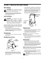
1
Operator’s Manual
Single Stage
Snow Thrower
Model 421R
IMPORTANT: Read safety rules and instructions carefully
Warning: This unit is equipped with an internal combustion engine and should not be used on or near any unimproved forestcovered, brush-covered or grass-covered land unless the engine’s exhaust system is equipped with a spark arrester meeting
applicable local or state laws (if any). If a spark arrester is used, it should be maintained in effective working order by the operator.
In the State of California the above is required by law (Section 4442 of the California Public Resources Code). Other states may have
similar laws. Federal laws apply on federal lands. A spark arrester for the muffler is available through your nearest engine authorized
service dealer or contact the service department, P.O. Box 368023 Cleveland, Ohio 44136-9722.
CUB CADET CORP. P.O. BOX 368023 CLEVELAND, OHIO 44136-9722
PRINTED IN U.S.A.
ECO No. 1405
FORM NO. 770-10005B.fm
(6/2000)
TABLE OF CONTENTS
Content
Page
Important Safe Operation Practices .................................................................. 3
Assembling Your Snow Thrower ....................................................................... 5
Know Your Snow Thrower................................................................................. 7
Operating Your Snow Thrower.......................................................................... 8
Making Adjustments.......................................................................................... 9
Maintaining Your Snow Thrower ....................................................................... 10
Off-Season Storage .......................................................................................... 11
Troubleshooting ................................................................................................ 12
Parts List ........................................................................................................... 13
FINDING MODEL NUMBER
This Operator’s Manual is an important part of your new snow thrower. It will help you to assemble, prepare and
maintain the unit for best performance. Please read and understand what it says.
Before you start assembling your new snow thrower, please locate the model plate on the
equipment and copy the information from it in the space provided below. The information on the
model plate is very important if you need help from our Customer Support Department or an
authorized dealer.
•
You can locate the model number by standing behind the unit in the operating position and looking down at
the dash panel . A sample model plate is explained below. For future reference, please copy the model
number and the serial number of the equipment in the space below.
(Model Number)
(Serial Number)
Copy the model number here:
Copy the serial number here:
CUB CADET CORP.
P.O. BOX 368023
CLEVELAND, OHIO 44136
CALLING CUSTOMER SUPPORT
If you have difficulty assembling this product or have any questions regarding the controls, operation
or maintenance of this unit, please call the Cub Cadet Customer Dealer Referral Line at 1-(800)-5281009. Please have your unit’s model number and serial number ready when you call. See previous
section to locate this information. By having the model and serial numbers ready, you help your Cub
Cadet dealer give you faster service.
For more details about your machine, visit our website at www.cubcadet.com
2
SECTION 1: IMPORTANT SAFE OPERATION PRACTICES
WARNING:
This symbol points out important safety instructions which, if not followed, could endanger the
personal safety and/or property of yourself and others. Read and follow all instructions in this manual before
attempting to operate this machine. Failure to comply with these instructions may result in personal injury. When you
see this symbol—heed its warning.
WARNING: Engine Exhaust, some of its constituents, and certain vehicle components contain or emit chemicals
known to State of California to cause cancer and birth defects or other reproductive harm.
DANGER: This machine was built to be operated according to the rules for safe operation in this manual. As with
any type of power equipment, carelessness or error on the part of the operator can result in serious injury. This
machine is capable of amputating hands and feet and throwing objects. Failure to observe the following safety
instructions could result in serious injury or death.
Training
1.
2.
3.
4.
5.
6.
7.
8.
Read, understand, and follow all instructions on the
machine and in the manual(s) before attempting to
assemble and operate. Keep this manual in a safe place
for future and regular reference and for ordering
replacement parts.
Be familiar with proper operation of all controls. Know
how to stop the machine and disengage controls quickly.
Never allow children under 14 years to operate this
machine. Children 14 years and over should read and
understand the operation instructions and safety rules in
this manual and should be trained and supervised by a
parent.
Never allow adults to operate this machine without
proper instruction.
Thrown objects can cause serious personal injury. Plan
your snow throwing pattern to avoid discharge of material
toward roads, bystanders and the like.
Keep bystanders, helpers, pets and children at least 75
feet from the machine while it is in operation. Stop
machine if anyone enters the area.
Exercise caution to avoid slipping or falling, especially
when operating in reverse.
9.
Preparation
1.
2.
3.
4.
5.
6.
7.
Thoroughly inspect the area where the equipment is to
be used. Remove all door mats, newspapers, sleds,
boards, wires and other foreign objects which could be
tripped over or thrown by the auger/impeller.
Always wear safety glasses or eye shields during
operation and while performing an adjustment or repair to
protect your eyes. Thrown objects which ricochet can
cause serious injury to the eyes.
Do not operate without wearing adequate winter outer
garments. Do not wear jewelry, long scarves or other
loose clothing which could become entangled in moving
parts. Wear footwear which will improve footing on
slippery surfaces.
Use a grounded three wire extension cord and receptacle
for all units with electric start engines.
Adjust collector housing height to clear gravel or crushed
rock surfaces.
Disengage all clutch levers before starting the engine.
Never attempt to make any adjustments while engine is
running, except where specifically recommended in the
operator’s manual.
Let engine and machine adjust to outdoor temperature
before starting to clear snow.
To avoid personal injury or property damage use extreme
care in handling gasoline. Gasoline is extremely
flammable and the vapors are explosive. Serious
personal injury can occur when gasoline is spilled on
yourself or your clothes which can ignite. Wash your skin
and change clothes immediately.
a. Use only an approved gasoline container.
b. Extinguish all cigarettes, cigars, pipes and other
sources of ignition.
c. Never fuel machine indoors.
d. Never remove gas cap or add fuel while the
engine is hot or running.
e. Allow engine to cool at least two minutes before
refueling.
f. Never over fill fuel tank. Fill tank to no more than
½ inch below bottom of filler neck to provide space
for fuel expansion.
g. Replace gasoline cap and tighten securely.
h. If gasoline is spilled, wipe it off the engine and
equipment. Move machine to another area. Wait 5
minutes before starting the engine.
i. Never store the machine or fuel container inside
where there is an open flame, spark or pilot light
(e.g. furnace, water heater, space heater, clothes
dryer etc.).
j. Allow machine to cool at least 5 minutes before
storing.
Operation
1.
2.
3.
4.
5.
3
Do not put hands or feet near rotating parts, in the auger/
impeller housing or discharge chute. Contact with the
rotating parts can amputate hands and feet.
The auger/impeller clutch lever is a safety device. Never
bypass its operation. Doing so, makes the machine
unsafe and may cause personal injury.
The clutch levers must operate easily in both directions,
and automatically return to the disengaged position when
released.
Never operate with a missing or damaged discharge
chute. Keep all safety devices in place and working.
Never run an engine indoors or in a poorly ventilated
area. Engine exhaust contains carbon monoxide, an
odorless and deadly gas.
6.
7.
8.
9.
10.
11.
12.
13.
14.
15.
16.
17.
18.
19.
20.
Maintenance And Storage
Do not operate machine while under the influence of
alcohol or drugs.
Muffler and engine become hot and can cause a burn. Do
not touch.
Exercise extreme caution when operating on or crossing
gravel surfaces. Stay alert for hidden hazards or traffic.
Exercise caution when changing direction and while
operating on slopes.
Plan your snow throwing pattern to avoid discharge
towards windows, walls, cars etc. To avoid property
damage or personal injury caused by a ricochet.
Never direct discharge at children, bystanders and pets
or allow anyone in front of the machine.
Do not overload machine capacity by attempting to clear
snow at too fast of a rate.
Never operate this machine without good visibility or
light. Always be sure of your footing and keep a firm hold
on the handles. Walk, never run.
Disengage power to the auger/impeller when
transporting or not in use.
Never operate machine at high transport speeds on
slippery surfaces. Look down and behind and use care
when in reverse.
If the machine should start to vibrate abnormally, stop the
engine, disconnect the spark plug and ground it against
the engine. Inspect thoroughly for damage. Repair any
damage before starting and operating.
Disengage all clutch levers and stop engine before you
leave the operating position (behind the handles). Wait
until the auger/impeller comes to a complete stop before
unclogging the discharge chute, making any
adjustments, or inspections.
Never put your hand in the discharge or collector
openings. Always use a clearing tool to unclog the
discharge opening.
Use only attachments and accessories approved by the
manufacturer (e.g. wheel weights, tire chains, cabs etc.).
If situations occur which are not covered in this manual,
use care and good judgment. Contact your dealer or
telephone 1-800-528-1009 for assistance and the name
of your nearest servicing dealer.
1.
Never tamper with safety devices. Check their proper
operation regularly.
2. Disengage all clutch levers and stop engine. Wait until
the auger/impeller come to a complete stop. Disconnect
the spark plug wire and ground against the engine to
prevent unintended starting before cleaning, repairing, or
inspecting.
3. Check bolts, and screws for proper tightness at frequent
intervals to keep the machine in safe working condition.
Also, visually inspect machine for any damage.
4. Do not change the engine governor setting or over-speed
the engine. The governor controls the maximum safe
operating speed of the engine.
5. Snow thrower shave plates and skid shoes are subject to
wear and damage. For your safety protection, frequently
check all components and replace with original
equipment manufacturer’s (O.E.M.) parts only. “Use of
parts which do not meet the original equipment
specifications may lead to improper performance and
compromise safety!”
6. Check clutch controls periodically to verify they engage
and disengage properly and adjust, if necessary. Refer to
the adjustment section in this operator’s manual for
instructions.
7. Maintain or replace safety and instruction labels, as
necessary.
8. Observe proper disposal laws and regulations for gas,
oil, etc. to protect the environment.
9. Prior to storing, run machine a few minutes to clear snow
from machine and prevent freeze up of auger/impeller.
10. Never store the machine or fuel container inside where
there is an open flame, spark or pilot light such as a water
heater, furnace ,clothes dryer etc.
11. Always refer to the operator’s manual for proper
instructions on off-season storage.
Your Responsibility:
•
4
Restrict the use of this power machine to persons who
read, understand and follow the warnings and
instructions in this manual and on the machine.
SECTION 2: ASSEMBLING YOUR SNOW THROWER
Unpacking From Carton
•
Before Assembly
Cut along corners of the carton and lay it down flat.
See Figure 1. Remove packing material.
Remove any loose parts included with unit (i.e.,
operator’s manual, etc.).
Roll unit out of carton. Check carton thoroughly for
any remaining loose part.
•
•
WARNING: Disconnect the spark plug wire
and ground it against the engine to prevent
unintended starting.
Raising Upper Handle
•
Remove loose parts
Loosen the hand knob on each side of the handle.
Remove packing material, if any.
Raise
handle
to here
Hand Knob
Roll unit out
Figure 1
Hardware Pack
1. Ignition Keys* (2)
Figure 3
*One key may be in the switch on snow thrower.
(Items 2 to 5 are illustrated in Figure 2.)
2.
3.
4.
5.
•
Eyebolt
Saddle Washer 5/16" I.D.
Hex Nuts 5/16-18 Thread (2)
Cotter Pin
•
Raise the upper handle in the direction shown in
Figure 3 till it clicks into the operating position.
Make sure not to pinch or crimp the cable.
Tighten the hand knobs.
Attaching Control Cable
The control cable may already be attached to the
control handle. If not attached, complete the following
steps to attach it to the snow thrower housing.
•
Eye Bolt
Hex Nut
Saddle
Washer
Route the control cable over the lower handle.
Insert the end of the cable into the hole in the
control housing as shown in Figure 4. Push the
plastic fitting until it locks into the control housing.
Cotter Pin
Bottom
Hole In
Control
Handle
Figure 2: Hardware Pack
Items Required For Assembly
1. Pair of pliers (not necessary, but helpful)
2. Two cycle engine oil (included)
3. Fresh gasoline
“Z” End
of Cable
Control
Housing
Plastic
Fitting
NOTE: All references to left or right side of the snow
thrower is from the operating position only.
Figure 4
5
•
Lift the control handle up, and hook the “Z” end of
the control cable into the bottom hole in the control
handle, from the outside to the inside . If necessary,
pull up on the end of the cable with a pair of pliers to
obtain slack in order to hook it into the control
handle. Hold the “Z” fitting with the pliers, not the
cable, to avoid damaging the cable.
•
•
Secure eyebolt with 5/16” saddle washer and hex
nut. The cupped side of washer goes against the
handle. Adjust lower hex nut until the eyebolt is
positioned so that the chute crank turns freely
(does not bind).
Move upper hex nut down against the lower handle.
Tighten lower hex nut securely.
NOTE: The upper hole in the control handle provides
for adjustment in belt tension. Refer to page 9 of this
manual for instructions.
Assembling Discharge Chute
Installing Chute Crank
•
•
•
The snow thrower has been shipped with the upper
chute pivoted all the way down. Assemble as follows:
Thread one 5/16” hex nut all the way onto the
eyebolt. See Figure 5. All necessary hardware is
included in the hardware pack shipped with your
unit. See Figure 2 for more details.
Slide the eyebolt onto the chute crank. Insert
eyebolt into the hole in the lower handle.
Turn the chute crank until the chute faces straight
to the front. See Figure 7.
Hand
Knob
Flat
Washer
Carriage
Bolt
Chute Crank
Front
Eye Bolt
Upper
Chute
Hex
Nuts
Saddle
Washer
Figure 7
•
Figure 5
•
•
•
Insert the chute crank into the coupler at the top
right side of the snow thrower. See Figure 6.
Rotate the crank to align holes, and insert the cotter
pin. Bend ends of cotter pin in opposite directions to
secure. See Figure 6.
Remove the hand knob, flat washer and carriage
bolt from the upper chute. See Figure 7.
Pivot the upper chute up so that there is no gap
between the upper and the lower chute. See Figure
8. Secure with hardware just removed.
Cotter Pin
No
Gap
Chute Crank
Coupler
Pivot
upper
chute
Figure 6
Figure 8
6
SECTION 3: KNOW YOUR SNOW THROWER
Be familiar with all the controls and their proper operation. Know how to stop the machine and disengage
them quickly.
•
Compare Figure 9 with the controls on your snow thrower before starting the machine or trying to operate it.
Auger Control
Handle
Upper
Handle
Chute Crank
Spark
Plug
Cover
Primer
Button
Ignition
Key
Discharge
Chute
Starter
Handle
Choke Lever
Off
On
Shave
Plate
Auger
Figure 9
Choke Lever
upper handle to engage the augers; release to
disengage.
Place choke lever in “ON” position to start a cold
engine.
Chute Crank
Primer Button
Used to inject fuel directly into the carburetor to insure
fast starts in cold weather. Follow engine manual to
prime engine.
Located on right side of dash panel, the chute crank
determines the direction that snow will be discharged.
Turn clockwise to discharge snow to the left; turn
counterclockwise to discharge to the right.
Ignition Key
Discharge Chute
Used to start engine. Put key in “ON” position to start.
The angle of the discharge chute controls the distance
that the snow is thrown. Tilt the discharge chute up for
greater distance; tilt down for less distance. Loosen the
hand knob on the side of the discharge chute to adjust.
Tilt the chute to the desired position, and tighten the
knob.
Starter Handle
Used to manually start the engine.
Spark Plug Cover
Spark plug located under the cover.
Auger Control Handle
Stopping Engine
Located on the upper handle, the auger control handle
is used to engage and disengage the augers. The snow
thrower is designed to be propelled by the rotation of
the augers. Pull the control handle back against the
•
7
Turn ignition key to OFF position and remove it
from the snow thrower.
SECTION 4: OPERATING YOUR SNOW THROWER
Before Starting
•
WARNING: Read, understand, and follow
all instructions and warnings on the machine
and in this manual before operating.
•
•
The spark plug wire was disconnected for safety
purposes during assembly. Attach spark plug wire
to spark plug before starting.
After making sure no bystanders or obstacles are in
front of the unit, engage the auger control handle.
See Figure 11. As the snow thrower starts to move,
maintain a firm hold on the handle, and guide the
snow thrower along the path to be cleared.
Release the auger control handle to stop the snow
throwing action and the forward motion.
Press auger
control handle
to engage
auger
Fuel & Oil Mixture
WARNING:
Use extreme care when
handling gasoline. Gasoline is extremely
flammable and the vapors are explosive.
Never fuel machine indoors or while the
engine is hot or running. Extinguish cigarettes,
cigars, pipes and other sources of ignition.
Turn handle
to change
discharge
direction
Your snow thrower uses a two cycle engine that
requires a mixture of gasoline and two cycle engine
oil. Refer to the engine operator’s manual for proper oil
and fuel recommendations.
• A plastic cup was provided inside the fuel fill
opening on the fuel tank. Remove and discard this
cup before filling up the tank. Use the seperate fuel
tank cap to close after fill-up.
Figure 11
Stopping Engine
•
•
Starting Engine
•
IMPORTANT: Keep the ignition key in a safe place.
Engine will not start without it.
To start the engine of your snow thrower, follow the
engine manual.
•
Operating Snow Thrower
ter
ea nce
r
G sta
Di
Upper
Discharge
Chute
Wipe all snow and moisture from the unit. Move the
choke lever back and forth several times and leave
it in the ON position.
Operating Tips
•
Di Les
sta s
nc
e
•
Hand
Knob
Discharge snow downwind whenever possible.
Slightly overlap each previously cleared path.
Lifting up on the handle will allow the rubber on the
augers to propel the snow thrower forward. Pushing
downward on the handle will raise the augers off
the ground and stop the forward motion.
NOTE: Excessive upward pressure on the handle will
result in premature wear on the rubber auger blades
which would not be covered by warranty.
•
Figure 10
•
Run the engine for a few minutes before stopping to
help dry any moisture on the engine.
To stop engine: Turn ignition key to OFF position
and remove it from the snow thrower.
•
Adjust the upper discharge chute up or down as
shown in Figure 10. Then use the chute crank to
position the discharge chute in order to discharge
snow with the wind.
Run the engine for a few minutes before stopping to
help dry any moisture on the engine.
Clean the snow thrower thoroughly after each use.
WARNING: Muffler, engine and surrounding
areas become hot and can cause a burn. Do
not touch.
8
SECTION 5: MAKING ADJUSTMENTS
Belt Tension
WARNING: NEVER attempt to make any
adjustments while the engine is running, except
where specified in the operator’s manual.
Shave Plate
Periodic adjustment of the belt tension may be required
due to normal stretch and wear on the belt. If augers
hesitate while turning although engine maintains same
speed, adjust tension following instructions below.
•
•
To check the adjustment of the shave plate, place
the unit on a level surface. See Figure 12. The
wheels, shave plate and augers should all contact
level surface. Note that if the shave plate is
adjusted too high, snow may blow under the
housing. If the shave plate wears out excessively,
or the unit will not self-propel, the shave plate may
be adjusted too low.
The upper hole in the control handle provides
adjustment for belt tension. To adjust, disconnect
the “Z” end of control cable from the bottom hole in
the control handle. See Figure 14 . Hook the cable
into the upper hole in control handle as shown here.
Upper
Hole
NOTE: On new units or units with a new shave plate
installed, the augers may be slightly off the ground.
Clutch
Cable
Control
Housing
Figure 14
If additional adjustment is required, follow steps below.
•
•
Augers
Shave Plate
Wheels
Figure 12
•
To adjust, tip the snow thrower back so that it rests
on the handle. Loosen the lock nuts and bolts which
secure the shave plate to the housing. See Figure
13. Move the shave plate to desired position and
retighten the nuts and bolts. Make certain all nuts
and bolts are tightened securely.
Remove the belt cover by removing five hex screws
that hold it in place. See Figure 16.
There are three adjustment holes provided in the
idler bracket assembly. See Figure 15. To adjust,
move the extension spring on the end of the clutch
cable to the next higher adjustment position on the
idler bracket assembly. Reassemble belt cover.
Idler
Bracket
High Position
Middle Position
Low Position
Spring on
End of Clutch
Auger Cable
Pulley
Figure 15
Carburetor
WARNING: If any adjustments need to be
made to the engine while the engine is running
(e.g. carburetor), keep clear of all moving
parts. Be careful of muffler, engine and other
surrounding heated surfaces.
Nuts & Bolts
•
Figure 13
9
Refer to the separate engine manual, packed with
your unit, for carburetor adjustment information.
SECTION 6: MAINTAINING YOUR SNOW THROWER
WARNING: Before servicing, repairing, or
•
inspecting, disengage all clutch levers and
stop engine. Wait until all moving parts have
come to a complete stop. Disconnect spark
plug wire and ground it against the engine to
prevent unintended starting.
Pull up on the idler pulley and slip the belt off the
engine pulley.
Push down on the idler pulley and slip the belt off
the auger pulley.
Reassemble new belt. See Figure 17.
Reinstall the belt cover.
•
•
•
General Recommendations
•
•
•
•
Always observe safety rules when performing any
maintenance.
All adjustments explained on page 9 should be
checked at least once each season.
Periodically check all fasteners and make sure
these are tight
Follow the maintenance schedule given below to
get quality performance from your snow thrower for
a long time.
Idler Pulley
Engine
Pulley
Auger
Pulley
Replacing Belt
Belt
Remove the belt cover by removing five hex
screws. See Figure 16.
Figure 17
Replacing Shave Plate
The shave plate is subject to wear. It should be
checked periodically. There are two wearing edges and
the shave plate can be reversed. See Figure 13.
•
Remove the four carriage bolts and hex lock nuts
which attach it to the snow thrower housing.
Install new shave plate, making sure the heads of
the carriage bolts are on the inside of the housing.
Adjust the shave plate according to procedure in
the “Making Adjustments” section of this manual.
Tighten securely.
•
Belt Cover
•
Hex
Screws
•
Figure 16
PRODUCT
Lubricate pivot points
Clean snow thrower
Check shave plate
Check belt
Clean engine
Check spark plug
10
es
fo r
Be
ce
as
to r
ea
ag
so
e
n
rs
ou
5h
On
y2
er
ch
Af
te r
ea
ee
fo r
Be
MAINTENANCE SCHEDULE
Ev
ac
us
hu
e
se
Customer Responsibilities
ENGINE
•
SERVICE DATES
Lubrication
Engine
•
•
Lubricate pivot points on the control handle and the
extension spring at the end of the clutch cable with
a light oil once every season and before storage of
the snow thrower at the end of the season.
•
Refer to the separate engine operator’s manual
packed with your snow thrower for all engine
maintenance procedures.
Check engine and snow thrower frequently for
loose hardware, and tighten as needed.
SECTION 7: OFF-SEASON STORAGE
WARNING: Never store engine with fuel in
•
•
tank indoors or in enclosed, poorly ventilated
areas where fuel fumes may reach an open
flame, spark or pilot light as on a furnace,
water heater, clothes dryer, or other gas
appliance.
•
•
Follow “Storage” instructions in the Engine Manual.
Store in a clean, dry area. Block the snow thrower
up so it is not resting on the rubber auger blades.
NOTE: When storing any type of power equipment in
an poorly ventilated or metal storage shed, care should
be taken to rustproof the equipment, especially springs,
cables and all moving parts.
Clean snow thrower thoroughly.
Lubricate as instructed above with a light oil.
11
SECTION 8: TROUBLESHOOTING GUIDE
Problem
Engine fails to start
Cause
Remedy
1.
Fuel tank empty, or stale fuel
1.
2.
3.
4.
5.
6.
Blocked fuel line
Key not in ON position
Spark plug wire disconnected
Faulty spark plug
Gasoline and oil not mixed correctly
2.
3.
4.
5.
6.
1.
2.
Unit running on choke
Fuel line blocked, or stale fuel
1.
2.
3.
4.
Water or dirt in fuel system
Carburetor out of adjustment
3.
4.
1.
Gasoline and oil not mixed correctly
1.
2.
Carburetor out of adjustment
2.
Drain fuel tank and refill with proper fuel
mixture.
Refer to engine manual.
Loss of power
1.
2.
3.
Spark plug wire loose
Vent in gas cap plugged
Exhaust port plugged.
1.
2.
3.
Connect and tighten spark plug wire.
Clear vent.
Clean port.
Excessive vibration
1.
Loose parts or damaged auger
1.
Stop engine immediately and disconnect
spark plug wire. Check for possible
damage. Tighten all bolts and nuts. Repair
as needed. If the problem persists, take
unit to an authorized service dealer.
Drive cable out of adjustment
1.
2.
Drive belt loose or damaged
2.
Adjust drive cable following instructions on
snow thrower.
Replace drive cable following instructions
on snow thrower.
1.
Discharge chute clogged
1.
2.
Foreign object lodged in auger
2.
3.
Drive cable not adjusted properly
3.
4.
Drive belt loose or damaged
4.
Engine runs erratic
Engine overheats
Unit fails to self-propel 1.
Unit fails to discharge
snow
Fill tank with clean fresh gasoline/oil
mixture as specified in the engine manual.
Clean fuel line
Insert key and turn to ON position
Connect wire to spark plug.
Clean spark plug, readjust gap, or replace.
Refer to engine manual
Move choke lever to off position.
Clean fuel line and fill tank with fresh,
clean gasoline.
Refer to engine manual on remedy.
Refer to engine manual.
Stop engine immediately and disconnect
spark plug wire. Clean discharge chute
and the auger housing.
Stop engine immediately and disconnect
spark plug wire. Remove object .
Adjust drive cable following instructions on
snow thrower.
Replace drive belt following instructions
on snow thrower.
NOTE: For repairs beyond the minor adjustments listed above, call the Customer Dealer Line at 1-800-528-1009 for
the dealer nearest you. Refer to separate engine manual, packed with your snow thrower, for engine information.
12
SECTION 9: PARTS LIST FOR MODEL 421R
5
9
10
4
2
3
7
8
6
1
7
Ref. No. Part No.
1. 710-0487
2. 710-1270
3. 712-0324
4. 720-0284
5. 720-0295
6. 725-0157
7. 736-0451
8. 746-0883
9. 747-0956
10. 749-0711A
4
Description
Carriage Screw
Oval C-Sunk Machine Screw
Hex Lock Nut
Wing Nut
Foam Grip: Handle
Cable Tie
Saddle Washer
Cable Housing w/o Throttle
Auger Bail: Gull Wing
Upper Handle: Gull Wing
NOTE: For painted parts, please refer to
the list of color codes below. Please add the
applicable color code, wherever needed, to
the part number to order a replacement part.
For instance, if a part, numbered 700-xxxx,
is painted Cub Yellow, the part number to
order would be 700-xxxx-0716.
Cub Yellow: 0716
Cub Beige: 0499
Cub Blue: 0685
Powder Black: 0637
13
SECTION 10: Model 421R
19
26
11
16
26
4
2
18
17
33
15
9
7
5
28
25 6
22
35
42 45
30
13
44
6
21
38
10
3
22
7
1
30
46 37 31
34
13
35
32 23 12
20
40
6
14
27
39
8
36
14
41
Model 421R
Ref. No.
1.
2.
3.
4.
5.
6.
7.
8.
9.
10.
11.
12.
13.
15.
16.
17.
18.
19.
20.
21.
22.
23.
Part No.
710-0167
710-0276
710-0323
710-0451
710-0642
710-1005
710-0773
710-0896
710-3015
711-0848A
712-0429
712-3010
712-0116
712-3027
720-0284
731-0851A
731-0915B
731-0921
731-1033
732-0357A
736-0108
736-0119
Part Description
Ref. No.
25.
26.
27.
28.
30.
31.
32.
33.
34.
35.
36.
37.
38.
39.
40.
41.
42.
43.
44.
45.
46.
Carriage Bolt
Carriage Bolt
Pan Head Screw
Carriage Bolt
Hex Washer Screw
Hex Washer Screw
Hex Washer Screw
Hex Washer Screw
Hex Cap Screw
Axle
Hex Center Lock Nut
Hex Nut
Hex Lock Nut
Hex Lock Flanged Nut
Knob
Chute Keeper
Lower Chute
Upper Chute
Shave Plate
Extension Spring
Flat Washer
Lock Washer
Part No.
736-0176
736-0159
736-0326
736-0329
741-0600
746-0910A
748-0234
749-0796
756-0313
784-5174
784-5176
784-5175B
684-0114
784-5485
753-0613
710-0352
784-5720
710-0451
736-0242
741-0475
710-0191
Part Description
Flat Washer
Washer
Flat Washer
Lock Washer
Ball Bearing
Cable—Clutch
Spacer
Handle—Lower
Flat Idler
Bearing Cup
Cover—Belt
Idler/Brake Bracket
Blower Housing
Auger Ass’y. Comp.
Auger Rubber Replacement
Hex Washer Screw
Crank Bracket
Cap Screw
Bell Washer
Bushing
Hex Screw
1
Ref. No.
Part No.
Description
1
734-1811
Wheel Assembly: 7 x 1.7”
NOTE: For painted parts, please refer to the list of color codes below. Please add the applicable color code, wherever
needed, to the part number to order a replacement part. For instance, if a part, numbered 700-xxxx, is painted Cub
Yellow, the part number to order would be 700-xxxx-0716.
Cub Yellow: 0716
Cub Beige: 0499
Cub Blue: 0685
Powder Black: 0637
15
Model 421R
17
11
28
21
10
26
7
25
2
27
7
9
23
8
6
13
15
14
19
29
4
22
24
18
7
3
16
5
5
20
16
Model 421R
Ref. No.
1.
2.
3.
4.
5.
6.
7.
8.
9.
10.
11.
12.
13.
14.
15.
16.
17.
18.
19.
20.
21.
22.
23.
24.
25.
26.
27.
28.
29.
Part No.
Part Description
684-0054A
Dash Assembly
684-0126
Chute Crank Assembly
710-1003
Special Screw: 310-16 x 0.375”
710-1090
Hex Flange Screw 5/16-18 x 1.25”
710-1268
Special screw
710-1652
Self-Tapping Screw 1/4-20 x .625”
712-3010
Hex Nut 5/16-18
714-0104
Hairpin Clip
714-0507
Cotter Pin
715-0138
Roll Pin
720-0201A
Chute Crank Knob
725-0201
Ignition Key
725-1341B
Ignition Key w/o Logo
725-1346
Ignition Switch Nut
725-1347
Ignition Switch Cap
725-1425
Switch: Key, Recoil Start
726-0100
Push Cap
731-1089A
Choke Cover
731-1133B
Spilling Cup
731-2109
Shroud: 21” Beige
735-0234
Rubber Grommet
736-0119
Lock Washer
736-0185
Flat Washer
736-0225
Internal Lock Washer
736-0451
Saddle Washer
747-0697
Eyebolt
747-0737
Upper Chute Crank
750-0785
Spacer
7510009636 Mitten Grip Handle
NOTE: For painted parts, please refer to
the list of color codes below. Please add the
applicable color code, wherever needed, to
the part number to order a replacement part.
For instance, if a part, numbered 700-xxxx,
is painted Cub Yellow, the part number to
order would be 700-xxxx-0716.
Cub Yellow: 0716
Cub Beige: 0499
Cub Blue: 0685
Powder Black: 0637
17
Model 421R
14
7
13
4
10
6
11
3
4
10
12
6
1
Ref. No
8
5
8 5
16
9
15
17
2
1.
2.
3.
4.
5.
6.
7.
8.
9.
10.
11.
12.
13.
14.
15.
16.
17.
Part No.
705-5139A
710-0157
710-1652
710-3013
710-3025
726-0205
731-2113A
736-0119
736-0242
736-0329
741-0475
751-0535
751-0540A
751-0800
754-0101A
756-0416B
756-0475
Description
Support Bracket: Gas Tank
Hex Bolt 5/16-24 x .75”
Self-Tapping Screw
Hex Screw 1/4-20 x .50”
Hex Screw
Hose Clamp
Cup
Lock Washer
Beleville Washer
Lock Washer
Plastic Bushing
Fuel Line Hose
Fuel Tank: 2 Quart
Fuel Cap
V-Belt
V-Pulley Half
V-Pulley Half
NOTE: For painted parts, please refer to the list of color codes below. Please
add the applicable color code, wherever needed, to the part number to order a
replacement part. For instance, if a part, numbered 700-xxxx, is painted Cub
Yellow, the part number to order would be 700-xxxx-0716.
Cub Yellow: 0716
Cub Beige: 0499
Cub Blue: 0685
Powder Black: 0637
18
Model 421R
19
MANUFACTURER’S LIMITED WARRANTY FOR:
TWO-YEAR RESIDENTIAL
ONE-YEAR COMMERCIAL
Proper maintenance of your Cub Cadet equipment is the owner’s responsibility. Follow the instructions in your
operator’s manual for correct lubricants and maintenance schedule. Your Cub Cadet dealer carries a
complete line of quality lubricants and filters for your equipment’s engine, transmission, chassis and
attachments.
Riding mowers, lawn tractors, garden tractors, Cub Cadet
attachments and home maintenance products
This limited warranty for residential users, covers any defect in materials or workmanship in your Cub Cadet
equipment for two years from the date of purchase for the first user purchaser. We will replace or repair any
part or parts without charge through your authorized Cub Cadet dealer.
Batteries have a one-year prorated limited warranty with 100% replacement during the first three months.
V-belts for either the traction drive or any attachments are covered for one year only.
Cub Cadet equipment used commercially is warranted for one year only.
(Commercial use is defined as either having hired operators or used for income producing purposes.)
Items not covered
The warranty does not cover routine maintenance items such as lubricants, filters (oil, fuel, air and hydraulic),
cleaning, tune-ups, brake and/or clutch inspection, adjustments made as part of normal maintenance, blade
sharpening, set-up, abuse, accidents and normal wear. It does not cover incidental costs such as transporting
your equipment to and from the dealer, telephone charges or renting a product temporarily to replace a
warranted product.
There is no other express warranty.
How to obtain service
Contact your authorized Cub Cadet servicing dealer who sold you your Cub Cadet equipment. If this dealer is
not available, see the Consumer Yellow Pages under “lawn mowers” for the name of a dealer near you.
If you need further assistance in finding an authorized Cub Cadet servicing dealer, contact:
Cub Cadet Corporation
Post Office Box 368023
Cleveland, Ohio 44136
How does state law apply?
This limited warranty gives you specific legal rights, and you may also have other rights which vary from state
to state.