1
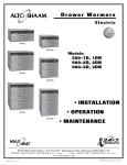
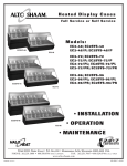
Catering Warmer Electric Models: 500-E/HD 500-E/Deluxe 500-E/HD 500-E/Deluxe • INSTALLATION • OPERATION • MAINTENANCE W164 N9221 Water Street • P.O. Box 450 • Menomonee Falls, Wisconsin 53052-0450 USA PHONE: 262.251.3800 • 800.558.8744 USA / CANADA FAX: 262.251.7067 • 800.329.8744 U . S . A . www.alto-shaam.com printed in u.s.a. ONLY MN-28945 • 10/11 Delivery.............................................................................. 1 Unpacking.......................................................................... 1 Safety Procedures and Precautions.................................... 2 Installation Site Installation............................................................. 3 Clearance Requirements............................................... 3 Weights......................................................................... 3 Dimension Drawing....................................................... 4 Stacking........................................................................ 4 Options and Accessories............................................... 4 Electrical Specifications................................................ 5 Operating Instructions User Safety Information................................................. 6 Heating Characteristics................................................. 6 Product Capacity........................................................... 6 Manual Control - Before Initial Use................................ 7 Electronic Control - Control Identification....................... 8 Electronic Control - Before Initial Use............................ 8 General Holding Guidelines........................................... 9 Care and Cleaning Cleaning and Preventative Maintenance...................... 10 Protecting Stainless Steel Surfaces............................. 10 Cleaning Agents.......................................................... 10 Cleaning Materials...................................................... 10 Care and Cleaning...................................................... 11 Sanitation Sanitation/Food Safety................................................ 12 Internal Food Product Temperatures........................... 12 Service Manual Control Thermostat and Heat Light Sequence...................... 13 Thermostat Calibration............................................ 13 Electronic Control Trouble Shooting Internal Electronic Components... 13 Trouble Shooting - Error Codes............................... 14 Probe and Air Sensor Testing.................................. 14 Service View - Manual Control................................ 15 Heat Cable Replacement Kits.................................. 16 Service Views - Electronic Control...................... 16-17 Wire Diagrams Always refer to the wire diagram(s) included with the unit for most current version. Warranty Transportation Damage and Claims.............. Back Cover Limited Warranty........................................... Back Cover DELIVERY UNPACKING This Alto-Shaam appliance has been thoroughly tested and inspected to ensure only the highest quality unit is provided. Upon receipt, check for any possible shipping damage and report it at once to the delivering carrier. See Transportation Damage and Claims section located in this manual. This appliance, complete with unattached items and accessories, may have been delivered in one or more packages. Check to ensure that all standard items and options have been received with each model as ordered. Save all the information and instructions packed with the appliance. Complete and return the warranty card to the factory as soon as possible to ensure prompt service in the event of a warranty parts and labor claim. This manual must be read and understood by all people using or installing the equipment model. Contact the Alto-Shaam Tech Team Service Department if you have any questions concerning installation, operation, or maintenance. 1. Carefully remove the appliance from the carton or crate. NOTE: All claims for warranty must include the full model number and serial number of the unit. 500-E ® ® NOTE: Do not discard the carton and other packaging material until you have inspected the unit for hidden damage and tested it for proper operation. 2. Read all instructions in this manual carefully before initiating the installation of this appliance. DO NOT DISCARD THIS MANUAL. This manual is considered to be part of the appliance and is to be provided to the owner or manager of the business or to the person responsible for training operators. Additional manuals are available from the Alto-Shaam Tech Team Service Department. 3. Remove all protective plastic film, packaging materials, and accessories from the appliance before connecting electrical power. Store any accessories in a convenient place for future use. installation / operation / service manual • 1. SAFETY PROCEDURES AND PRECAUTIONS Knowledge of proper procedures is essential to the safe operation of electrically and/or gas energized equipment. In accordance with generally accepted product safety labeling guidelines for potential hazards, the following signal words and symbols may be used throughout this manual. 1. This appliance is intended to cook, hold or process foods for the purpose of human consumption. No other use for this appliance is authorized or recommended. 2. This appliance is intended for use in commercial establishments where all operators are DANGER Used to indicate the presence of a hazard that WILL cause severe personal injury, death, or substantial property damage if the warning included with this symbol is ignored. WARNING Used to indicate the presence of a hazard that CAN cause personal injury, possible death, or major property damage if the warning included with this symbol is ignored. familiar with the purpose, limitations, and associated hazards of this appliance. Operating instructions and warnings must be read and understood by all operators and users. 3. Any troubleshooting guides, component views, and parts lists included in this manual are for general reference only and are intended for use by qualified technical personnel. 4. This manual should be considered a permanent part of this appliance. This manual and all supplied instructions, diagrams, schematics, parts lists, notices, and labels must remain with the appliance if the item is sold or moved to another location. CAUTION Used to indicate the presence of a hazard that can or will cause minor or moderate personal injury or property damage if the warning included with this symbol is ignored. CAUTION Used to indicate the presence of a hazard that can or will cause minor personal injury, property damage, or a potential unsafe practice if the warning included with this symbol is ignored. NOTE For equipment delivered for use in any location regulated by the following directive: DO NOT DISPOSE OF ELECTRICAL OR ELECTRONIC EQUIPMENT WITH OTHER MUNICIPAL WASTE. N O T E : Used to notify personnel of installation, operation, or maintenance information that is important but not hazard related. 500-E installation / operation / service manual • 2. INSTALLATION SITE INSTALLATION This appliance, complete with unattached items and accessories, may be delivered in one or more packages. Check to insure that all accessories that were ordered have been received with the unit. Alto-Shaam holding cabinets are designed for the purpose of maintaining hot food at a temperature for safe consumption. The unit must be installed on a level surface in a location that will permit the equipment to function for its intended purpose and allow adequate access for proper cleaning and maintenance. CLEA R A NCE R EQ UIR EM ENTS 3 inches (76mm) top, bottom, right and left NET WEIGHT 500-E/HD: 59 lb. (27 kg) 500-E/Deluxe: 76 lb. (34 kg) The appliance must not be used in any area where it will be affected by steam, grease, dripping water, high temperatures, or any other severely adverse conditions. DANGER ELECTRICAL CONNECTIONS MUST BE MADE BY A QUALIFIED SERVICE TECHNICIAN IN ACCORDANCE WITH APPLICABLE ELECTRICAL CODES. 500-E CAUTION TO PREVENT PERSONAL INJURY, USE CAUTION WHEN MOVING OR LEVELING THIS APPLIANCE. installation / operation / service manual • 3. INSTALLATION SITE INSTALLATION Cord Length: 125V - 5 ft. (1524mm) 230V - 8 ft. (2438mm) 208-240V - 8 ft. (2438mm) 21-1/2" (547 mm) Cavity 39-1/4" (997 mm) 25-9/16" (650 mm) 23-3/16" (589 mm) C L 39" (991 mm) 25" (635 mm) 22-1/2" (572 mm) Electrical Connection 1-1/2” (38 mm) from top 2-1/2" (64 mm) 8-1/16" (205 mm) Electrical Outside Dimensions C L Electrical Connection 1-5/8" (40mm) from top Cord Length: 125V - 5 ft. (1524mm) 230V - 8 ft. (2438mm) 208-240V - 8 ft. (2438mm) 500-E/HD 500-E/Deluxe 350 100 F OFF 150 300 1-1/4" (31 mm) 19-1/16" (484 mm) 13-13/16" (351 mm) Cavity 200 19-3/8" (493 mm) 250 16-13/16" (411 mm) 17-3/16" (437 mm) STACKING Cabinets can be stacked in multiples. There are four (4) 3/16" (5mm) rounded projections on the top and bottom of each cabinet to permit stacking A center support stacking hardware kit (E-5091) must be used to stack the deluxe cabinets. O PTIO NS & A CCES S O R IES 500-E/HD stacked height: 38-1/8" (968mm) 500-E/Deluxe stacked height: 40-1/16" (1018mm) Shelf, chrome plated wire 13-1/8" (333 mm) Cavity 16-1/8" (409mm) 17-1/8" (434 mm) Casters*, 3" (76mm) (4) Casters*, 5" (127mm) (4) Caster Stand Assembly with 5" (127mm) casters (4) Legs*, 6" (152mm) (4) 500-E/HD 500-E/Deluxe — 14227* — 4007* 15377 — — 5205* Leg Stand Assembly, with 6" (152mm) legs (4) 15378 — Pan Slide Support (2 11002 — required ) Stand Base Assembly Stacking Hardware ( center support , between units ) Transport Door Latches ( factory installation ) SH-2107 — — E-5089* — E-5091 LT-2035 — *stand base assembly must be ordered when ordering casters or legs 500-E installation / operation / service manual • 4. INSTALLATION ELECTRICAL 1.An identification tag is permanently mounted on the cabinet. 2.Plug the unit into a properly grounded receptacle ONLY. Arcing will occur when connecting or disconnecting the unit unless all controls are in the “OFF” position. 3.Position the unit so the cord is easily accessible in case of any emergencies. If necessary, a proper receptacle or outlet configuration, as required for the unit, must be installed by a licensed electrician in accordance with applicable, local electrical codes. For CE approved units: To prevent an electrical shock hazard between the appliance and other appliances or metal parts in close vicinity, an equalization-bonding stud is provided. An equalization bonding lead must be connected to this stud and the other appliances / metal parts to provide sufficient protection against potential difference. The terminal is marked with the following symbol. NOTE: CE approved appliances must be connected to an electrical circuit that is protected by an external GFCI outlet. ELECTRICAL 500-E/HD voltage phase cycle/hz amps kW 125 (agcy) 1 60 4.0 0.5 208-240 (agcy)1 50/60 5.0 1.2 at 208V 50/60 4.4 0.9 at 240V 50/60 5.0 1.2 230 (agcy) 1 50/60 4.8 1.1 plug config. nema 5-15p 15a-125v plug nema 6-15p 15a-250v plug ENSURE POWER SOURCE MATCHES VOLTAGE STAMPED ON APPLIANCE NAMEPLATE. DANGER To avoid electrical shock, this appliance MUST be adequately grounded in accordance with local electrical codes or, in the absence of local codes, with the current edition of the National Electrical Code ANSI/ NFPA No. 70. In Canada, all electrical connections are to be made in accordance with CSA C22.1, Canadian Electrical Code Part 1 or local codes. DANGER IMPROPER INSTALLATION, ALTERATION, ADJUSTMENT, SERVICE, OR MAINTENANCE COULD RESULT IN SEVERE INJURY, DEATH, OR CAUSE PROPERTY DAMAGE. READ THE INSTALLATION, OPERATING AND MAINTENANCE INSTRUCTIONS THOROUGHLY BEFORE INSTALLING OR SERVICING THIS EQUIPMENT. cee 7/7 220-230v plug CAUTION plug config. THIS SECTION IS PROVIDED FOR THE ASSISTANCE OF QUALIFIED SERVICE TECHNICIANS ONLY AND 500-E/DELUXE voltage phase cycle/hz amps kW 125 (agcy) 1 60 4.8 0.6 208-240V at 208 1 50/60 3.4 0.8 at 240 1 50/60 3.0 0.6 230 (agcy)1 50/60 3.3 0.8 DANGER 5-15p 15a-125v plug nema nema 6-15p 15a-250v plug cee 7/7 220-230v plug IS NOT INTENDED FOR USE BY UNTRAINED OR UNAUTHORIZED SERVICE PERSONNEL. Wire diagrams are located inside the bonnet of the unit. 500-E installation / operation / service manual • 5. INSTALLATION USER SAFETY INFORMATION This appliance is intended for use in commercial establishments where all operators are familiar with the purpose, limitations, and associated hazards of this appliance. Operating instructions and warnings must be read and understood by all operators and users. CA PA CITY Up to approximately 87 lbs. (39.45 kg) STANDARD: FULL SIZE PANS: GASTRONORM: — Three (3) 12" x 20" x 4"( 1/1: 530 x 325 x 100mm) ONE-HALF SIZE PANS: ake sure the unit is connected to the M appropriate power source. 1.U se hand protection when handling hot items. 2. Be certain only hot foods are placed into the cabinet. 3. T o avoid personal injury and damage to the unit, treat glass with care. Remember –– glass can shatter. — Six (6) 12" x 10" x 4" (1/2: 265 x 325 x 100mm) OPTION: FULL SIZE PANS: GASTRONORM: — Four (4) 12" x 20" x 2-1/2" (1/1: 530 x 325 x 65mm) ONE-HALF SIZE PANS: — Eight (8) 12" x 10" x 2-1/2" (1/2: 265 x 325 x 65mm) For the option to accommodate 2-1/2" (65mm) deep pans, one set of (2) #11002 Pan Slide Supports are required. Remove the two (2) #1220 Pan Slides Supports from the center pan position inside the cabinet, and replace with the two (2) #11002 Pan Slide Supports using the same Pan Slide Mounting Screws (SC-2268). HEATING CHARACTERISTICS The cabinet is equipped with a special, low heat density, heating cable. Through the Halo Heat concept, the heating cable is mounted against the walls of the warming compartment to provide an evenly applied, thermostat controlled, heat source. The design and operational characteristics of the cabinet eliminate the need for a moisture pan or a heat circulating fan. Through even heat application, the quality of a food product is maintained up to several hours. STANDARD OPTIONAL 6: #1220 PAN SLIDES 4: #1220 PAN SLIDES 2: #11002 PAN SLIDES CAUTION TO PREVENT PERSONAL INJURY, USE CAUTION WHEN MOVING OR LEVELING THIS APPLIANCE. 500-E installation / operation / service manual • 6. OPERATION MANUAL CONTROL BEFORE INITIAL USE Clean appliance with a clean, damp cloth and mild soap solution. Clean and install the pans, shelves and side racks. 3.Reset the thermostat to 160°F (71°C). For potatoes - 180°F (82°C). 1.Turn thermostat to 200°F (93°C) and preheat for 30 minutes. When the thermostat is turned clockwise to an “ON” position, the indicator light will illuminate and will remain lit as long as the unit is calling for heat. Close the ventilation openings inside the door to accelerate heating. Check to make certain the cabinet door is securely closed, and reset the thermostat to 160°F (71°C). THIS WILL NOT NECESSARILY BE THE FINAL SETTING. The proper temperature range for the products being held will depend on the type and quantity of product. When holding food for prolonged periods, it is advisable to periodically check the internal temperature of each item with a food thermometer to assure maintenance of the proper temperature range of 140° to 160°F (60° to 71°C). The indicator light will go OUT when the air temperature inside the unit reaches the temperature set by the operator. It will then V erify that the fan in the back of the unit is cycle “ on / off ” at this holding point. Verify operating and turning without any visual the full preheated temperature with the holding restrictions. temperature gauge located on the control panel of the cabinet. 2.Load the cabinet with hot food only. The purpose of the holding cabinet is to maintain hot food at proper serving temperature. Before loading the cabinet with food, use a food thermometer to make certain all products are at an internal temperature range of 140° to 160°F (60° to 71°C). Any food product not within the proper temperature range should be heated before loading into the holding cabinet. Heat Indicator Light Some foods (ribs, fish, potatoes, etc.) will create humidity inside the warmer. Allow the surface of these foods to stabilize for a short period of time before placing the warm food inside the unit. Do not add water to the unit. 500-E installation / operation / service manual • 7. Thermostat Thermostat Gauge OPERATION ELECTRONIC CONTROL Before Initial Use: Clean appliance with a clean, damp cloth and mild soap solution. Glass cleaner or distilled vinegar can be used on any glass. Clean and install the pans, shelves and side racks. 1. Preheat at 200°F (93°C) for 30 minutes. Press the ON key, and set the temperature to ON/OFF Key 200°F (93°) by using the UP/DOWN arrow keys. Press the ON/OFF key once and the power indicator Allow a minimum of 30 minutes preheating light will illuminate. Press and hold the ON/OFF time before loading the holding cabinet with key until the LED display turns off (at least three food. Closing the vents on the inside of the seconds) and power indicator light goes out. door will speed the preheating process. The UP/DOWN Arrow Key LED heat indicator light will go “Out” after approximately 30 minutes preheat time, or The UP and DOWN arrow keys are I used for a variety when the air temperature inside the unit reaches of settings when selecting the holding temperature. If o the temperature set by the operator. The Set an arrow key is pressed and released, the display will indicator will light up anytime the temperature is show the current set temperature for two seconds. If set or reset. an arrow key is held (at least eight seconds), the value will change at a rapid rate. If the arrow key is pressed 2. Load with hot food only. and released in rapid succession, the set temperature The purpose of the holding cabinet is to maintain will change by increments of one degree. hot food at proper serving temperature. Only hot food should be placed into the cabinet. ENABLE/DISABLE BEEPER Before loading the cabinet with food, use a food A beeper sounds when an error code is displayed. thermometer to make certain all products are at To choose between beeper on and beeper off mode, an internal temperature range of 140° to 160°F the control must be off, then press and hold the (60° to 71°C). Any food product not within the DOWN arrow key until either “ON” or “OFF” is proper temperature range should be heated shown in the LED display. Release arrow key when before loading into the holding cabinet. desired mode is displayed. °F / °C 3. Reset the control to 160°F (71°C). FAHRENHEIT/CELSIUS Check to make certain the cabinet door is With the control off, to choose between Fahrenheit securely closed, and reset to 160°F (71°C) by and Celsius, press and hold the UP arrow key until using the UP/DOWN keys . THIS WILL NOT either °F or °C is shown in LED display. Release key NECESSARILY BE THE FINAL SETTING. The when desired setting is displayed. proper temperature range--or closing or opening The control has a four-digit LED display. When the door vents--will depend on the type and the display is on, it will show current holding quantity of product. When holding food for temperature, as well as diagnostic information. prolonged periods, it is advisable to periodically check the internal temperature of each item with CONTROL LOCK a food thermometer to assure maintenance of the The warmer controls can be locked so that no changes proper temperature range of 140° to 160°F can be made to the set temperature. (60° to 71°C). To lock the display, press and hold the ON/OFF key and the Up Arrow key at the same time. The lock LED will illuminate. When the lock LED is illuminated, additional programming will not be functional other than the key sequence required to unlock the panel. To unlock the display, press and hold the ON/OFF key and the Down Arrow key at the same time. The lock LED will extinguish. The panel keys will resume normal function. 500-E installation / operation / service manual • 8. OPERATION GENERAL HOLDING GUIDELINES Chefs, cooks and other specialized food service personnel employ varied methods of cooking. Proper holding temperatures for a specific food product must be based on the moisture content of the product, product density, volume, and proper serving temperatures. Safe holding temperatures must also be correlated with palatability in determining the length of holding time for a specific product. Halo Heat maintains the maximum amount of product moisture content without the addition of water, water vapor, or steam. Maintaining maximum natural product moisture preserves the natural flavor of the product and provides a more genuine taste. In addition to product moisture retention, the gentle properties of Halo Heat maintain a consistent temperature throughout the cabinet without the necessity of a heat distribution fan, thereby preventing further moisture loss due to evaporation or dehydration. When product is removed from a high temperature cooking environment for immediate transfer into equipment with the lower temperature required for hot food holding, condensation can form on the outside of the product and on the inside of plastic containers used in self-service applications. Allowing the product to release the initial steam and heat produced by high temperature cooking can alleviate this condition. To preserve the safety and quality of freshly cooked foods however, a maximum of 1 to 2 minutes must be the only time period allowed for the initial heat to be released from the product. This unit is equipped with a thermostat control between 60° and 200°F (16° and 93°C). If the unit is equipped with vents, close the vents for moist holding and open the vents for crisp holding. Use a metal-stemmed thermometer to measure the internal temperature of the product being held. Adjust the thermostat setting to achieve the best overall setting based on internal product temperature. 500-E HOLDING TEMPERATURE RANGE MEAT FAHRENHEIT CELSIUS BEEF ROAST — Rare 130°F 54°C BEEF ROAST — Med/Well Done 155°F 68°C BEEF BRISKET 160° — 175°F 71° — 79°C CORN BEEF 160° — 175°F 71° — 79°C PASTRAMI 160° — 175°F 71° — 79°C PRIME RIB — Rare STEAKS — Broiled/Fried 130°F 54°C 140° — 160°F 60° — 71°C 160°F 71°C VEAL RIBS — Beef or Pork 160° — 175°F 71° — 79°C HAM 160° — 175°F 71° — 79°C PORK 160° — 175°F 71° — 79°C LAMB 160° — 175°F 71° — 79°C CHICKEN — Fried/Baked 160° — 175°F 71° — 79°C DUCK 160° — 175°F 71° — 79°C TURKEY 160° — 175°F 71° — 79°C GENERAL 160° — 175°F 71° — 79°C POULTRY FISH/SEAFOOD FISH — Baked/Fried 160° — 175°F 71° — 79°C LOBSTER 160° — 175°F 71° — 79°C SHRIMP — Fried 160° — 175°F 71° — 79°C 120° — 140°F 49° — 60°C 160° — 175°F 71° — 79°C 80° — 100°F 27° — 38°C BAKED GOODS BREADS/ROLLS MISCELLANEOUS CASSEROLES DOUGH — Proofing EGGS —Fried 150° — 160°F 66° — 71°C FROZEN ENTREES 160° — 175°F 71° — 79°C HORS D'OEUVRES 160° — 180°F 71° — 82°C PASTA 160° — 180°F 71° — 82°C PIZZA 160° — 180°F 71° — 82°C POTATOES PLATED MEALS 180°F 82°C 140° — 165°F 60°— 74°C 60° — 93°C SAUCES 140° — 200°F SOUP 140° — 200°F 60° — 93°C VEGETABLES 160° — 175°F 71° — 79°C THE HOLDING TEMPERATURES LISTED ARE SUGGESTED GUIDELINES ONLY . ALL FOOD HOLDING SHOULD BE BASED ON INTERNAL PRODUCT TEMPERATURES . ALWAYS FOLLOW LOCAL HEALTH TEMPERATURE REQUIREMENTS . installation / operation / service manual • 9. ( HYGIENE ) REGULATIONS FOR ALL INTERNAL CLEANING AND PREVENTIVE MAINTENANCE PROTECTING STAINLESS STEEL SURFACES It is important to guard against corrosion in the care of stainless steel surfaces. Harsh, corrosive, CLEANING AGENTS Use non-abrasive cleaning products designed for use on stainless steel surfaces. Cleaning agents must be chloride-free compounds and must not or inappropriate chemicals can completely destroy the contain quaternary salts. Never use hydrochloric acid (muriatic acid) on stainless steel surfaces. protective surface layer Always use the proper cleaning agent at the of stainless steel. Abrasive pads, steel wool, or metal implements will abrade manufacturer's recommended strength. Contact your local cleaning supplier for surfaces causing damage to this protective coating product recommendations. and will eventually result in areas of corrosion. Even water, particularly hard water that contains CLEANING MATERIALS high to moderate concentrations of chloride, will cause oxidation and pitting that result in rust and corrosion. In addition, many acidic foods spilled and left to remain on metal surfaces are contributing factors that will corrode surfaces. Proper cleaning agents, materials, and methods are vital to maintaining the appearance and life of this appliance. Spilled foods should be The cleaning function can usually be accomplished with the proper cleaning agent and a soft, clean cloth. When more aggressive methods must be employed, use a non-abrasive scouring pad on difficult areas and make certain to scrub with the visible grain of surface metal to avoid surface scratches. Never use wire brushes, metal scouring pads, or scrapers to remove food residue. removed and the area wiped as soon as possible but at the very least, a minimum of once a day. Always thoroughly rinse surfaces after using a cleaning agent and wipe standing water as quickly as possible after rinsing. CAUTION RA PE RS NO SC IR E BRU NO S ST E EL P A DS NO S HE W 500-E TO PROTECT STAINLESS STEEL SURFACES, COMPLETELY AVOID THE USE OF ABRASIVE CLEANING COMPOUNDS, CHLORIDE BASED CLEANERS, OR CLEANERS CONTAINING QUATERNARY SALTS. NEVER USE HYDROCHLORIC ACID (MURIATIC ACID) ON STAINLESS STEEL. NEVER USE WIRE BRUSHES, METAL SCOURING PADS OR SCRAPERS. installation / operation / service manual • 10. CARE AND CLEANING The cleanliness and appearance of this unit will contribute considerably to operating efficiency and savory, appetizing food. Good equipment that is kept clean works better and lasts longer. 6. C lean control panel, door vents, door handles, and door gaskets thoroughly since these areas harbor food debris. 7. R inse surfaces by wiping with sponge and clean warm water. 8. R emove excess water with sponge and wipe dry with a clean cloth or air dry. Leave door open until interior is completely dry. Replace shelves. CLEAN THE UNIT THOROUGHLY AFTER EACH USE 9. I nterior can be wiped with a sanitizing solution after cleaning and rinsing. This solution must be approved for use on stainless steel food contact surfaces. 1. D isconnect unit from power source, and let cool. 10.T o help maintain the protective film coating on polished stainless steel, clean the exterior of the cabinet with a cleaner recommended for stainless steel surfaces. Spray the cleaning agent on a clean cloth and wipe with the grain of the stainless steel. 2. R emove, cover or wrap, and store unused products under refrigeration. 3. R emove all detachable items such as wire shelves, side racks, and any drip pan. Clean these items separately. 4. C lean interior with a damp cloth or sponge and any good commercial detergent at the recommended strength. 5. S pray heavily soiled areas with a water soluble degreaser and let stand for 10 minutes, then remove soil with a plastic scouring pad. NOTE: A void the use of abrasive cleaning compounds, chloride based cleaners, or cleaners containing quaternary salts. Never use hydrochloric acid (muriatic acid) on stainless steel. DANGER DISCONNECT UNIT FROM POWER SOURCE BEFORE CLEANING OR SERVICING. 11. Clean glass with a window cleaner. Always follow appropriate state or local health (hygiene) regulations regarding all applicable cleaning and sanitation requirements for foodservice equipment. DANGER AT NO TIME SHOULD THE INTERIOR OR EXTERIOR BE STEAM CLEANED, HOSED DOWN, OR FLOODED WITH WATER OR LIQUID SOLUTION OF ANY KIND. DO NOT USE WATER JET TO CLEAN. SEVERE DAMAGE OR ELECTRICAL HAZARD COULD RESULT. WARRANTY BECOMES VOID IF APPLIANCE IS FLOODED 500-E installation / operation / service manual • 11. √S A N I T A T I O N Food flavor and aroma are usually so closely related that it is difficult, if not impossible, to separate them. There is also an important, inseparable relationship between cleanliness and food flavor. Cleanliness, top operating efficiency, and appearance of equipment contribute considerably to savory, appetizing foods. Good equipment that is kept clean, works better and lasts longer. Most food imparts its own particular aroma and many foods also absorb existing odors. Unfortunately, during this absorption there is not distinction between GOOD and BAD odors The majority of objectionable flavors and odors troubling food service operations are caused by bacteria growth. Sourness, rancidity, mustiness, stale or other OFF flavors are usually the result of germ activity. The easiest way to insure full, natural food flavor is through comprehensive cleanliness. This means good control of both visible soil (dirt) and invisible soil (germs). A through approach to sanitation will provide essential cleanliness. It will assure an attractive appearance of equipment, along with maximum efficiency and utility. More importantly, a good sanitation program provides one of the key elements in the prevention of food-borne illnesses. A controlled holding environment for prepared foods is just one of the important factors involved in the prevention of food-borne illnesses. Temperature monitoring and control during receiving, storage, preparation, and the service of foods are of equal importance. The most accurate method of measuring safe temperatures of both hot and cold foods is by internal product temperature. A quality thermometer is an effective tool for this purpose, and should be routinely used on all products that require holding at a specific temperature. A comprehensive sanitation program should focus on the training of staff in basic sanitation procedures. This includes personal hygiene, proper handling of raw foods, cooking to a safe internal product temperature, nd the routine monitoring of internal temperatures from receiving through service. Most food-borne illnesses can be prevented through proper temperature control and a comprehensive program of sanitation. Both these factors are important to build quality service as the foundation of customer satisfaction. Safe food handling practices to prevent foodborne illness is of critical importance to the health and safety of your customers. HACCP, an acronym for Hazard Analysis (at) Critical Control Points, is a quality control program of operating procedures to assure food integrity, quality, and safety. Taking steps necessary to augment food safety practices is both cost effective and relatively simple. While HACCP guidelines go far beyond the scope of this manual, additional information is available by contacting: CENTER FOR FOOD SAFETY AND APPLIED NUTRITION FOOD AND DRUG ADMINISTRATION 1-888-SAFEFOOD INTERNAL FOOD PRODUCT TEMPERATURES H OT FOOD S DANGER ZONE 40° TO 140°F (4° TO 60°C) CRITICAL ZONE 70° TO 120°F (21° TO 49°C) SAFE ZONE 140° TO 165°F (60° TO 74°C) COLD FOOD S DANGER ZONE ABOVE 40°F (ABOVE 4°C) SAFE ZONE 36° TO 40°F (2° TO 4°C) FROZ E N FOOD S DANGER ZONE ABOVE 32°F (ABOVE 0°C) CRITICAL ZONE 0° TO 32°F (-18° TO 0°C) SAFE ZONE 0°F or below (-18°C or below) 500-E installation / operation / service manual • 12. √S E R V I C E • M A N U A L C O N T R O L THERMOSTAT & INDICATOR LIGHT SEQUENCE THERMOSTAT CALIBRATION Whenever the thermostat is turned “ON,” the indicator light will indicate the power ON/OFF condition of the heating cable, and consequently, the cycling of the cabinet as it maintains the dialed cavity temperature. If this light does not illuminate after normal start-up, the main power source, thermostat, and/or indicator light must be checked. The thermostat is precision calibrated at the factory. Normally, no adjustment or recalibration is necessary unless the thermostat has been mishandled in transit, changed or abused while in service. A thermostat with a sensing bulb operates on hydraulic pressure, consequently, any bending of the bulb results in a change in its volume, and alters the accuracy of the thermostat calibration. If the warming cabinet does not hold the temperature as dialed, the calibration of the thermostat must be checked. If the warming cabinet fails to heat or heats continuously with the thermostat “OFF,” the thermostat must be initially checked for proper operation. If these items are checked and found to be in order, a continuity and resistance check of the heating cable should be made. SEE CIRCUIT DIAGRAM. A thermostat should be checked or recalibrated by placing a quality, thermal indicator at the center of an empty holding cavity. DO NOT CALIBRATE WITH ANY FOOD PRODUCT IN THE CABINET. The thermostat should be set, and should be allowed to stabilize at that setting for a minimum of one hour. The center of the thermal swing of the air temperature within the cabinet should approximately coincide with the thermostat setting. If calibration is necessary, the calibration screw should be adjusted with great care. The calibration screw of the thermostat is located in the thermostat dial shaft. With the shaft held stationary, a minute, clockwise motion of the calibration screw appreciably lowers the thermostat setting. A reverse, or counter-clockwise motion appreciably raises the thermostat setting. After achieving the desired cycling of the thermostat, the calibration screw must be sealed. Place a few drops of enamel sealant directly on the calibration screw. (Red nail polish or equivalent is acceptable.) TROUBLE SHOOTING INTERNAL ELECTRICAL COMPONENTS A. No power. Display will not light. 1.Verify that power is available at the outlet or junction box. 2.Verify that the circuit breaker switch on the back of the unit is turned on. 3.V erify that the power cord is not open. Check continuity with a VOM meter. 4. I f none of the above steps help, call a qualified service technician or refer to the Service Manual for this particular oven. This section is provided for the assistance of qualified technicians only and is not intended for use by untrained or unauthorized service personnel. If your Alto-Shaam® unit is not operating properly, check the following before calling your Authorized Alto-Shaam® Service Agent: * C heck the power flow to the unit. Plug in outlet? Circuit breaker switch at back of unit turned on? Do not attempt to repair or service the unit beyond this point. Contact Alto-Shaam® for the nearest authorized service agent. Repairs made by any other service agents without prior authorization by Alto-Shaam® will void the warranty on the unit. 500-E installation / operation / service manual • 13. √S E R V I C E • E L E C T R O N I C C O N T R O L TRO UB L E S H O O T I N G Error Code Description E-10 E-11 E-20 E-21 E-30 E-31 E-50 Possible Cause Cavity air sensor reading < 5°F. Verify sensor integrity. See sensor test instructions below. Cavity air sensor reading > 517°F. Verify sensor integrity. Cavity air sensor open See sensor test instructions below. Product probe is shorted Product probe reading < 5°F. Verify sensor integrity. Oven will cook in time only See sensor test instructions below. Product probe is open Product Probe reading > 517°F. Verify sensor integrity. Oven will cook in time only See sensor test instructions below. Unit has not reached set-point for more than 90 minutes. Under temperature Note: 30 minutes for Rotisseries and Convection Ovens Unit has been higher than 25°F above the maximum cavity set-point for Over temperature more than 2 minutes. Note: Holding Cabinets with this error code are more than 145°F higher than the maximum set-point. Temp. measurement error Contact factory. Cavity air sensor shorted E-51 Temp. measurement error Contact factory. E-60 Real time clock error Data set to factory default. Ensure that date and time are correct if applicable. E-61 Real time clock error Contact factory. E-70 Configuration connector error (DIP switch) Refer to wiring diagram for the particular model and ensure dip switches on the control match the settings called out on the WD. If the dip switch settings are correct according to the print replace the control. E-78 Voltage low Voltage below 90 VAC on a 125 VAC unit, or below 190 VAC on a 208-240 VAC unit. Correct voltage. E-79 Voltage high Voltage over 135 VAC on a 125 VAC unit, or over 250 VAC on a 208-240 VAC unit. Correct voltage. E-80 EEPROM Error Ensure that all temperatures and times are properly set. Contact factory if problem persists. E-81 EEPROM Error Contact factory. E-82 EEPROM Error Contact factory. E-83 EEPROM Error Contact factory. E-85 EEPROM Error All timers, if previously on, are now off. Possible bad EEPROM. E-86 EEPROM Error Stored HACCP memory corrupted. HACCP Address reset to 1. Possible bad EEPROM. Contact factory if problem persists. E-87 EEPROM Error Stored offsets corrupted. Offsets reset to 0. Control may need a recalibration. Possible bad EEPROM. Contact factory if problem persists. E-88 EEPROM Error All timer set-points are reset to 1 minute. Timers, if previously on, are now off. Possible bad EEPROM. E-90 Button stuck A button has been held down for >60 seconds. Adjust control. Error will reset when the problem has been resolved. E-dS Datakey error Datakey digital signature incompatible. Cycle power, and install compatible Datakey if error persists. E-dT Datakey error Datakey incompatible with control. Install compatible Datakey. E-dU Datakey unplugged Install Datakey and cycle power to control to clear error. Note: If in doubt, always cycle the power to the control and contact factory if the problem persists. To test probe and air sensor: Tes t probe and air sensor by placing sensor in ice water bath and using an ohmmeter set on the ohm scale. The reading should be 100 ohms resistance. If it is more than 2 ohms higher or lower, sensor needs to be replaced . 500-E installation / operation / service manual • 14. SERVICE MANUAL CONTROL Part numbers and drawings are subject to change without notice. ITEM DESCRIPTION 1 TOP 2 3 4 PART NO. QTY ITEM PART NO. QTY 1 11 HI-LIMIT THERMOSTAT (230V) TT-3859 1 TOP MOUNTING SCREWS SC-2425 9 12 THERMOSTAT TT-3057 1 CORD AND PLUG SET (125V) CD-3029 1 THERMOSTAT KNOB (Fahrenheit) KN-3469 1 CORDSET: 230V CD-3984 1 THERMOSTAT KNOB (Celsius) KN-3474 1 CORDSET: 208-240V CD-3858 1 HEAT INDICATOR LIGHT (125V) LI-3027 1 INLET (125V) IT-3001 1 HEAT INDICATOR (230V and 208-240V) LI-3951 1 INLET (208-240V) INLET (230V) IT-3857 1 14 INTERIOR AMBIENT TEMP. GAUGE GU-3273 1 1 15 CONTROL PANEL OVERLAY PE-2882 1 1360/1355 1 16 DOOR ASSEMBLY, RIGHT-HAND 15016 1 DOOR ASSEMBLY, LEFT-HAND 5125 1 HINGE SET (1 pair of 2 hinges) HG-2015 1 HINGE MOUNTING SCREWS SC-2072 12 DOOR HANDLE HD-2007 1 DOOR HANDLE MOUNTING SCREWS SC-2073 3 DOOR STRIKER MOUNTING SCREWS SC-2071 3 19 DOOR GASKET (length): 5.1’ (1555mm) GS-2398 1 20 PAN SLIDES CASING, BOTTOM 6 CASING, BOTTOM, MOUNTING RIVETS RI-2100 10 7 FAN, 125V FA-3485 1 FA-3342 1 FA-33073 1 FAN, 208-240V, 230V FAN BLADE 13 IT-33173 5 8 DESCRIPTION 4986 17 18 INSULATION: 25" x 54" (635mm x 1372mm) 25" x 54" (635mm x 1372mm) 125V IN-22364 1 IN-2381 1 9* CABLE CONNECTION HARDWARE 10 CABLE KIT, 230V 4873 1 CABLE KIT, 208-240V 4878 1 4979 1 CABLE KIT, 230V 500-E 21 1220 6 P AN SLIDE MOUNTING SCREWS SC-2268 12 CARRYING HANDLE HD-2021 4 MOUNTING SCREWS SC-2070 16 installation / operation / service manual • 15. SERVICE ELECTRONIC CONTROL Exterior View a m c b l jk d e i h g ITEM f DESCRIPTION 1 CONTROL PANEL 2 3 PART NO. QTY ITEM PE-25464 1 HINGE HG-2015 DOOR GASKET E2132GS 4 DOOR HANDLE WITH STRIKER 5 DOOR WITH WINDOW 6 7 DESCRIPTION PART NO. QTY 8 CASING 1001383 1 2 9 DOOR HANDLE STRIKER ONLY HD-2575 1 1 10 CARRY HANDLES HD-2010 4 HD-2007 1 11 CARRY HANDLE BACKER 11017 4 E5078 1 12 SENSOR SN-33541 1 SIDE RAILS SR-25477 2 13 SENSOR BLOCK BK-24427 1 FEET BM-22606 4 14 TOP 1001349 1 Part numbers and drawings are subject to change without notice. HEAT CABLE REPLACEMENT SERVICE KITS PART DESCRIPTION #4873 125V #4878 208-240V #4879 230V CB-3045 CABLE HEATING ELEMENT — 85 feet 112 feet CB-3044 CABLE HEATING ELEMENT 52 feet — — CR-3226 RING CONNECTOR 4 4 6 IN-3488 INSULATION CORNER 1 foot 1 foot 1 foot BU-3105 SHOULDER BUSHING 4 4 6 BU-3106 CUP BUSHING 4 4 6 ST-2439 STUD 4 4 6 NU-2215 HEX NUT 8 8 12 SL-3063 INSULATING SLEEVE TA-3540 ELECTRICAL TAPE 4 4 6 1 roll 1 roll 1 roll Part numbers and drawings are subject to change without notice. 500-E installation / operation / service manual • 16. SERVICE ELECTRONIC CONTROL Electrical Components ITEM DESCRIPTION PART NO. QTY 1 BUSHING BU-3013 1 2 BEEPER BP-3567 1 3 BUSHING BU-3007 2 4 RELAY RL-34434 1 5 CLAMP CM-3585 1 6 BOARD, POWER BA-33554 1 7 SENSOR BLOCK SN-33546 1 8 TERMINAL BLOCK BK-3019 1 9 GROUND SCREW SC-2190 1 10 SWITCH, CIRCUIT BREAKER SW-33826 1 11 CONTROL ASSEMBLY CC-34222 1 12 BUSHING BU-3964 1 13 CORDSET, 125V CD-3232 1 CORDSET, 230V CD-3922 1 CORDSET, 208-240V CD-3551 1 Cabinet Front a b c d e f g Part numbers and drawings are subject to change without notice. k h d i j Back of Cabinet m j l Top Rear View DANGER DISCONNECT UNIT FROM POWER SOURCE BEFORE CLEANING OR SERVICING. 500-E CAUTION THIS SECTION IS PROVIDED FOR THE ASSISTANCE OF QUALIFIED SERVICE TECHNICIANS ONLY AND IS NOT INTENDED FOR USE BY UNTRAINED OR UNAUTHORIZED SERVICE PERSONNEL. installation / operation / service manual • 17. 500-E installation / operation / service manual • 18. 500-E installation / operation / service manual • 19. 500-E installation / operation / service manual • 20. 500-E installation / operation / service manual • 21. 500-E installation / operation / service manual • 22. TRANSPORTATION DAMAGE and CLAIMS 1. 2. 3. 4. 5. 6. 7. 8. All Alto-Shaam equipment is sold F.O.B. shipping point, and when accepted by the carrier, such shipments become the property of the consignee. Should damage occur in shipment, it is a matter between the carrier and the consignee. In such cases, the carrier is assumed to be responsible for the safe delivery of the merchandise, unless negligence can be established on the part of the shipper. Make an immediate inspection while the equipment is still in the truck or immediately after it is moved to the receiving area. Do not wait until after the material is moved to a storage area. Do not sign a delivery receipt or a freight bill until you have made a proper count and inspection of all merchandise received. Note all damage to packages directly on the carrier’s delivery receipt. Make certain the driver signs this receipt. If he refuses to sign, make a notation of this refusal on the receipt. If the driver refuses to allow inspection, write the following on the delivery receipt: Driver refuses to allow inspection of containers for visible damage. Telephone the carrier’s office immediately upon finding damage, and request an inspection. Mail a written confirmation of the time, date, and the person called. Save any packages and packing material for further inspection by the carrier. Promptly file a written claim with the carrier and attach copies of all supporting paperwork. We will continue our policy of assisting our customers in collecting claims which have been properly filed and actively pursued. We cannot, however, file any damage claims for you, assume the responsibility of any claims, or accept deductions in payment for such claims. LIMITED WARRANTY Alto-Shaam, Inc. warrants to the original purchaser only that any original part that is found to be defective in material or workmanship will, at Alto-Shaam's option, subject to provisions hereinafter stated, be replaced with a new or rebuilt part. The parts warranty period is as follows: For the refrigeration compressor on Alto-Shaam Quickchillers™, five (5) years from the date of installation. For the heating element on Halo Heat® cook/hold ovens, as long as the original purchaser owns the oven. For all other parts, one (1) year from the date of installation or fifteen (15) months from the shipping date, whichever occurs first. The labor warranty period is one (1) year from the date of installation or fifteen (15) months from the shipping date, whichever occurs first. Alto-Shaam will bear normal labor charges performed during standard business hours, excluding overtime, holiday rates or any additional fees. To be valid, a warranty claim must be asserted during the applicable warranty period. This warranty is not transferable. THIS WARRANTY DOES NOT APPLY TO: 1. Calibration. 2. Replacement of light bulbs, door gaskets, and/or the replacement of glass due to damage of any kind. 3. Equipment damage caused by accident, shipping, improper installation or alteration. 4. Equipment used under conditions of abuse, misuse, carelessness or abnormal conditions, including but not limited to, equipment subjected to harsh or inappropriate chemicals, including but not limited to, compounds containing chloride or quaternary salts, poor water quality, or equipment with missing or altered serial numbers. 5. Damage incurred as a direct result of poor water quality, inadequate maintenance of steam generators and/or surfaces affected by water quality. Water quality and required maintenance of steam generating equipment is the responsibility of the owner/operator. 6. Damage caused by use of any cleaning agent other than Alto-Shaam's Combitherm® Cleaner, including but not limited to damage due to chlorine or other harmful chemicals. Use of Alto-Shaam's Combitherm® Cleaner on Combitherm® ovens is highly recommended. 7. Any losses or damage resulting from malfunction, including loss of product or consequential or incidental damages of any kind. 8. Equipment modified in any manner from original model, substitution of parts other than factory authorized parts, removal of any parts including legs, or addition of any parts. This warranty is exclusive and is in lieu of all other warranties, express or implied, including the implied warranties of merchantability and fitness for a particular purpose. In no event shall Alto-Shaam be liable for loss of use, loss of revenue or profit, or loss of product, or for any indirect, special, incidental, or consequential damages. No person except an officer of Alto-Shaam, Inc. is authorized to modify this warranty or to incur on behalf of Alto-Shaam any other obligation or liability in connection with Alto-Shaam equipment. E f fect i v e 09/10 RECORD THE MODEL AND SERIAL NUMBER OF THE APPLIANCE FOR EASY REFERENCE. ALWAYS REFER TO BOTH MODEL AND SERIAL NUMBER IN ANY CONTACT WITH ALTO-SHAAM REGARDING THIS APPLIANCE. Model: ______________________________________________ Date Installed: ______________________________________________________ Voltage: ______________________________________________ Purchased From: ___________________________________________ Serial Number: _____________________________________________________________________________________________________________ W164 N9221 Water Street PHONE: ● P.O. Box 450 ● Menomonee Falls, Wisconsin 53052-0450 ● U.S.A. 262.251.3800 • 800.558-8744 USA/CANADA FAX: 262.251.7067 • 800.329.8744 U.S.A. ONLY www.alto-shaam.com PRINTED IN U.S.A.