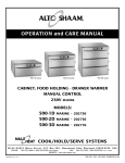
1
INSTALLATION
OPERATION
AND
500-1D
500-1DN
MAINTENANCE
MANUAL
500-2D
500-2DN
DRAWER
WARMERS
500-3D
500-3DN
Manual or Electronic
Control
MODELS:
500-1D, 1DN
500-2D, 2DN
500-3D, 3DN
W 1 6 4 N 9 2 2 1 W a t e r S t r e e t • P. O . B o x 4 5 0 • M e n o m o n e e F a l l s , W i s c o n s i n 5 3 0 5 2 - 0 4 5 0 U S A
PHONE: 262.251.3800
FAX: 262.251.7067 • 800.329.8744 U.S.A. ONLY
WEBSITE:
800.558-8744 USA/CANADA
262.251.1907 INTERNATIONAL
www.alto-shaam.com
PRINTED IN U.S.A.
#818 • 1/2005
D R AW E R WA R M E R S
®
U N PA C K I N G a n d S E T- U P
E L E C T R I C A L I N S TA L L AT I O N
The Alto-Shaam Drawer Warmer has
been thoroughly tested, checked for
calibration, and inspected to insure only
the highest quality cabinet is provided.
When you receive your unit, check for
any possible shipping damage and
report it at once to the delivering
carrier. See Transportation Damage
and Claims section located in this manual.
1. An identification tag is permanently mounted on
the cabinet.
®
®
Save all the information and instructions packed inside
the cabinet. Complete and return the warranty card to
the factory as soon as possible to assure prompt service
in the event of a warranty parts and labor claim.
Alto-Shaam drawer warmers are designed for the
purpose of maintaining hot food at a temperature for
safe consumption. The unit must be installed in a
location that will permit the equipment to function for
its intended purpose and allow adequate access for
proper cleaning and maintenance.
NOTE: Any claims for warranty must include the
full model number and serial number of
the cabinet.
PH
PATENT NOS. 3521030
4595247
®
2. Plug cabinet into a properly grounded receptacle
ONLY, positioning the unit so the power supply
cord is easily accessible in case of an emergency.
ENSURE POWER SOURCE MATCHES
VOLTAGE S TA M P E D
O N N A M E P L AT E O F U N I T
3. If necessary, a proper receptacle or outlet configuration as required for this unit, must be installed
by a licensed electrician in accordance with
applicable, local electrical codes.
For 230V units: To prevent an electrical shock hazard
between the appliance and other appliances or metal parts
in close vicinity, an equalization-bonding stud is provided.
An equalization bonding lead must be connected to this
stud and the other appliances / metal parts to provide
sufficient protection against potential difference. The
terminal is marked with the following symbol .
H E AT I N G C H A R A C T E R I S T I C S
The drawer warmer is equipped with a special heating
cable. Through this Halo Heat concept, the heating
cable is mounted against the walls of the unit to provide
an evenly applied heat source controlled by a
thermostat. The design and operational characteristics
of the unit eliminate the need for a moisture pan or a
heat circulating fan. Through even heat application,
the quality of food products is maintained up to several
hours or more.
Disconnect unit from power source
before cleaning or servicing.
At no time should a warming
compartment, drawer assembly
or the unit be steamed cleaned,
washed down or flooded with
water or liquid solution.
Do not use water jet to clean.
Severe damage or electrical
hazard could result
Warranty becomes void if unit is flooded.
S TA R T- U P / I N S TA L L AT I O N
1. The unit must not be installed in any area where it may be affected by steam, grease, dripping water, high
temperatures, or any other severely adverse conditions.
2. Minimum clearances are required for proper air ventilation including 3-inches (76mm) at the back,
2-inches (51mm) at the top, and 1-inch (25mm) at both sides. On site venting for proper airflow must
also be provided for built-in counter installations.
3. Before operating the unit, clean both the interior and exterior of the unit with a clean, damp cloth and mild
soap solution. Rinse carefully. Clean and install the drawer warmer pan(s). The drawer assembly is
completely removable. Clean as a sanitation measure.
# 8 1 8 I N S TA L L AT I O N / O P E R AT I O N / S E RV I C E M A N U A L • 1.
I N S TA L L AT I O N
Manual Control, 120V Unit
Panel Overlay
High Limit Switch
Thermostat Knob
Thermometer
Manual Control, 208-240V, 230V Units
Panel Overlay
Drawer Assembly
Drawer Bearing
Drawer Rail
Stud & Nut
Electronic Control
Panel Overlay
# 8 1 8 I N S TA L L AT I O N / O P E R AT I O N / S E RV I C E M A N U A L • 2.
Heat Indicator
Light
I N S TA L L AT I O N
• Outside Dimensions •
40-1/16" (1018mm)
22-13/16" (579mm)
24-3/8" (618mm)
16-7/16" (418mm)
CL
CL
HANDLE
11-11/16"
(296mm)
18-7/8" (479mm)
26-3/16" (663mm)
HI-LO Switch available only on 500-1DN and 500-2DN.
500-1D
500-2D
500-3D
11-3/4"
(298mm)
19" (482mm)
26-1/8" (663mm)
6-3/4" (171mm)
29-15/16" (761mm)
ELECTRICAL CONNECTION
24-5/8" (625mm)
HI-LO Switch available only on 500 -1D and 500 -2D.
ELECTRICAL CONNECTION
HANDLE
1-11/16" (42mm)
ELECTRICAL CONNECTION
Narrow
Drawer
Warmers
500-1DN
500-2DN
500-3DN
Wide
Drawer
Warmers
1-11/16" (42mm)
ELECTRICAL CONNECTION
50-7/8" (1291mm)
28-1/8" (714mm)
6-3/4" (171mm)
FOR LEG STAND OR CASTER STAND ASSEMBLY
FOR LEG STAND OR CASTER STAND ASSEMBLY
Options & Accessories
Built-In Trim Kit
➥ 500-1D . . . . . . . . . . . . . .
➥ 500-1DN . . . . . . . . . . . .
➥ 500-2D . . . . . . . . . . . . . .
➥ 500-2DN . . . . . . . . . . . .
➥ 500-2D for BU-48, BU-72
➥ 500-2D for BU-96 . . . . . .
➥ 500-3D . . . . . . . . . . . . . .
➥ 500-3DN . . . . . . . . . . . .
Caster Stand Assembly
➥ wide drawer warmers . . . .
➥ narrow drawer warmers . . .
.
.
.
.
.
.
.
.
.
.
.
.
.
.
.
.
44224
44225
44226
44227
55532
44231
44228
44229
Drawer Assembly with vents
➥ wide drawer warmers . . . . . . 55536
➥ narrow drawer warmers . . . . . 55537
Leg Stand Assembly
➥ wide drawer warmers . . . . . . 15380
➥ narrow drawer warmers . . . . . 55535
Pan, Oversize, 15"x20"x5" . . . PN-2123
➥ Perforated Pan Grid, . . . . . . . 1231
Perforated Pan Grid, 12"x20" . . 16642
➥ fits standard drawer pan (PN-25088)
. . 15379
. . 55534
# 8 1 8 I N S TA L L AT I O N / O P E R AT I O N / S E RV I C E M A N U A L • 3.
O P E R AT I O N - M A N U A L C O N T R O L
1.
2.
3.
Dual wattage control.
The one and two drawer, 120V warmers are
provided with a HIGH/LOW power switch.
Use the HIGH position at 1000 watts for meats,
potatoes, and vegetables — use the LOW
position at 500 watts for breads and rolls.
Preheat at 200°F (93°C) for 30 minutes.
When the thermostat is turned clockwise to an
“ON” position, the indicator light will illuminate
and will remain lit as long as the unit is calling
for heat. Allow a minimum of 30 minutes of
preheating before loading the warmer with food.
The indicator light will go “OUT” after
approximately 30 minutes, or when the air
temperature inside the unit reaches the
temperature set by the operator.
Load the drawer warmer with pans of
hot food only.
The purpose of the unit is to maintain hot food
at proper serving temperatures. Only hot food
should be placed into the warmer. Before
loading the unit with food, use a food
thermometer to make certain all food products
are at an internal temperature range of
140° to 160°F (60° to 71°C). All food not
within the proper temperature range should be
heated before putting into the drawer warmer.
4. Reset the thermostat to 160°F (71°C).
Check to make certain the drawer is
securely closed, and reset the thermostat to
160°F (71°C).
THIS WILL NOT NECESSARILY BE THE
FINAL SETTING.
The proper temperature range for the food being
held will depend on the type and quantity of
product. When holding food for prolonged
periods, it is advisable to periodically check the
internal temperature of each item to assure
maintenance of the proper temperature range.
TEMPERATURE
THERMOSTAT
GAUGE
HEAT INDICATOR LIGHT
DUAL WATTAGE CONTROL
120V
ONLY
# 8 1 8 I N S TA L L AT I O N / O P E R AT I O N / S E RV I C E M A N U A L • 4.
O P E R AT I O N - E L E C T R O N I C C O N T R O L
LED DISPLAY
POWER INDICATOR LIGHT
HEAT INDICATOR
LIGHT
ON/OFF POWER KEY
LOCK INDICATOR
UP/DOWN
ARROWS
ON/OFF KEY
Press the on/off key once and the power indicator light will
illuminate. Press and hold the on/off key until the LED
display turns off (at least three seconds) and on/off indicator
goes out.
1. Preheat at 200°F (93°C) for 30 minutes.
Press the ON key, and set the temperature to
200°F (93C°) by using the UP/DOWN arrow
keys. Allow a minimum of 30 minutes
preheating time before loading the drawer
UP/DOWN ARROW KEY
warmer with food. The LED heat indicator
The up and down arrow keys are used for a variety of settings
light will go “OUT” after approximately 30
when selecting the holding temperature. If an arrow key is pressed
minutes
preheat time, or when the air
and released the display will show the current set temperature for
temperature inside the unit reaches the
two seconds. If an arrow key is held (at least eight seconds), the
temperature set by the operator.
value will change at a rapid rate. If the arrow key is pressed and
released in rapid succession, the set temperature will change by
increments of one degree.
°F /°C
2. Load with pans of hot food only.
The purpose of the warmer is to maintain hot
ENABLE/DISABLE BEEPER
food at proper serving temperature. Only hot
A beeper sounds when an error code is displayed.
food should be placed into the unit. Before
To choose between beeper on and beeper off mode, the
loading with food, use a food thermometer to
control must be OFF, then press and hold the down arrow
make certain all products are at an internal
key until either "ON" or "OFF" is shown in the LED display.
temperature range of 140° to 160°F (60° to
Release arrow key when desired mode is displayed.
71°C). Any food product not within the
proper temperature range should be heated
FAHRENHEIT / CELSIUS
before loading into the unit.
With the control OFF, to choose between Fahrenheit and Celsius,
press and hold the up arrow key until either °F or °C is shown
3. Reset the control to 160°F (71°C).
in the LED display. Release key when desired setting is displayed.
Check to make certain the drawer is securely
The control has a four-digit LED display. When the display
is ON, it will show current holding temperature, as well as
diagnostic information.
CONTROL LOCK
The warmer controls can be locked so that no changes can
be made to the set temperature.
To lock the display, press and hold the ON/OFF key and
the Up Arrow key at the same time. The lock indicator will
illuminate. When the lock indicator is illuminated, additional
programming will not be functional other than the key
sequence required to unlock the panel.
To unlock the display, press and hold the ON/OFF key and
the Down Arrow key at the same time. The lock indicator
will extinguish. The panel keys will resume normal function.
closed, and reset to 160°F (71°C) by using
the UP/DOWN keys.
THIS WILL NOT NECESSARILY BE THE
FINAL SETTING.
The proper temperature range will depend on
the type and quantity of product. When
holding food for prolonged periods, it is
advisable to periodically check the internal
temperature of each item with a food
thermometer to assure maintenance of the
proper temperature range of
140° to 160°F (60° to 71°C).
# 8 1 8 I N S TA L L AT I O N / O P E R AT I O N / S E RV I C E M A N U A L • 5.
O P E R AT I O N
FOOD PRODUCT TIPS
Bread and Rolls
Breads and rolls are traditionally difficult to hold for prolonged periods due to the very low moisture content
of these products. For best results and longest possible holding life, it is recommended these products be
placed in a plastic bag while in the warming drawer. Breads and rolls should be held at a temperature no
higher than 120° to 140°F (49° to 60°C).
Potatoes
— for the best results in holding potatoes:
1. Do not overcook.
Regardless of the temperature at which potatoes are cooked or what type of oven is used, it is important
that this product does not achieve a final internal product temperature in excess of 195°F (91°C). Overcooking will further reduce the moisture content and consequently, reduce the holding life. Potatoes
should be removed from the oven when they reach an internal temperature of approximately 190°F
(88°C). After they are removed from the oven, the internal temperature will continue to increase.
2. Allow potatoes to stabilize before placing in drawer warmer.
When potatoes are removed from a conventional high-temperature oven, they have an extremely high
surface temperature. If they are placed in the drawer warmer while they are this hot on the outside,
moisture will be pulled from the inside of the potato and condensation will form on the outside. Holding
results under these conditions will not be totally satisfactory. Remove potatoes from the oven and allow
the surface temperature to stabilize before placing them in the controlled holding atmosphere of the
drawer warmer.
# 8 1 8 I N S TA L L AT I O N / O P E R AT I O N / S E RV I C E M A N U A L • 6.
O P E R AT I O N
GENERAL HOLDING GUIDELINES
Chefs, cooks and other
specialized food service
personnel employ varied
methods of cooking.
Proper holding
temperatures for a specific
food product must be
based on the moisture
content of the product,
product density, volume,
and proper serving
temperatures. Safe
holding temperatures must
also be correlated with
palatability in determining
the length of holding time
for a specific product.
Halo Heat maintains the
maximum amount of
product moisture content
without the addition of
water, water vapor, or
steam. Maintaining
maximum natural product
moisture preserves the
natural flavor of the
product and provides a
more genuine taste. In
addition to product
moisture retention, the
gentle properties of Halo
Heat maintain a consistent
temperature throughout
the cabinet without the
necessity of a heat
distribution fan, thereby
preventing further
moisture loss due to
evaporation or
dehydration.
H O L D I N G T E M P E R AT U R E R A N G E
MEAT
FA H R E N H E I T
CELSIUS
BEEF ROAST — Rare
140°F
60°C
BEEF ROAST — Med/Well Done
160°F
71°C
BEEF BRISKET
160° — 175°F
71° — 79°C
CORN BEEF
160° — 175°F
71° — 79°C
PASTRAMI
160° — 175°F
71° — 79°C
PRIME RIB — Rare
140°F
60°C
140° — 160°F
60° — 71°C
160°F
71°C
VEAL
160° — 175°F
71° — 79°C
HAM
160° — 175°F
71° — 79°C
PORK
160° — 175°F
71° — 79°C
LAMB
160° — 175°F
71° — 79°C
CHICKEN — Fried/Baked
160° — 175°F
71° — 79°C
DUCK
160° — 175°F
71° — 79°C
TURKEY
160° — 175°F
71° — 79°C
GENERAL
160° — 175°F
71° — 79°C
FISH — Baked/Fried
160° — 175°F
71° — 79°C
LOBSTER
160° — 175°F
71° — 79°C
SHRIMP — Fried
160° — 175°F
71° — 79°C
120° — 140°F
49° — 60°C
160° — 175°F
71° — 79°C
80° — 100°F
27° — 38°C
EGGS —Fried
150° — 160°F
66° — 71°C
FROZEN ENTREES
160° — 175°F
71° — 79°C
HORS D'OEUVRES
160° — 180°F
71° — 82°C
PASTA
160° — 180°F
71° — 82°C
PIZZA
160° — 180°F
71° — 82°C
180°F
82°C
STEAKS — Broiled/Fried
RIBS — Beef or Pork
POULTRY
FISH/SEAFOOD
BAKED GOODS
BREADS/ROLLS
In an enclosed holding
environment, too much
moisture content is a
condition which can be
relieved. A product
achieving extremely high
temperatures in preparation
must be allowed to decrease
in temperature before being
placed in a controlled
holding atmosphere. If the
product is not allowed to
decrease in temperature,
excessive condensation will
form increasing the moisture
content on the outside of
the product.
Most Halo Heat holding
equipment is provided with
a thermostat control between
60° and 200°F (16° to 93°C).
If the unit is equipped with
vents, close the vents for
moist holding and open the
vents for crisp holding.
MISCELLANEOUS
CASSEROLES
DOUGH — Proofing
POTATOES
PLATED MEALS
180°F
82°C
140° — 200°F
60° — 93°C
SOUP
140° — 200°F
60° — 93°C
VEGETABLES
160° — 175°F
71° — 79°C
SAUCES
The holding temperatures listed are suggested guidelines only.
# 8 1 8 I N S TA L L AT I O N / O P E R AT I O N / S E RV I C E M A N U A L • 7.
If the unit is equipped with a
thermostat indicating a range
of between 1 and 10, use a
metal-stemmed indicating
thermometer to measure the
internal temperature of the
product(s) being held. Adjust
the thermostat setting to
achieve the best overall
setting based on internal
product temperature.
CARE and CLEANING
The cleanliness and appearance of this unit will contribute considerably
to operating efficiency and savory, appetizing food. Good equipment
kept clean works better and lasts longer.
THOROUGHLY CLEAN THE UNIT DAILY
1. Disconnect unit from power source,
and let cool.
2. Remove, cover or wrap, and
refrigerate food.
NOTE: Avoid the use of abrasive cleaning, compounds,
chloride based cleaners, or cleaners containing
quaternary salts. Never use hydrochloric acid
(muriatic acid) on stainless steel.
5. Wipe control panel, vents, handles, and gaskets
3. Remove drawer pans and clean
separately. The drawer assembly is
completely removable. Remove from the
cabinet and clean to prevent a build-up of
food residue from interfering with the function of
the drawer assembly. Regular cleaning will help
prolong the life of these parts.
4. Clean interior metal surfaces of the unit with a
damp, clean cloth and any good commercial
detergent or grease solvent at the recommended
strength. Use a plastic scouring pad or oven cleaner
for difficult areas. Rinse carefully to remove all
residue and wipe dry.
thoroughly since these areas harbor food debris.
6. Interior can be wiped with a sanitizing solution
after cleaning and rinsing. This solution must be
approved for use on stainless steel food contact
surfaces.
7. To help maintain the protective film coating on
polished stainless steel, clean the exterior of the
unit with a cleaner recommended for stainless steel
surfaces. Spray the cleaning agent on a cloth and
wipe with the grain of the stainless steel.
Always follow appropriate state or local health
(hygiene) regulations regarding all applicable cleaning
and sanitation requirements for foodservice equipment.
At no time should the inside or outside of the
unit be washed down, flooded with
water or liquid solution.
NEVER STEAM CLEAN.
Do not use water jet to clean.
Severe damage or electrical hazard
could result.
Warranty becomes void if unit is flooded.
# 8 1 8 I N S TA L L AT I O N / O P E R AT I O N / S E RV I C E M A N U A L • 8.
SANITATION
Food flavor and aroma are usually so closely related
that it is difficult, if not impossible, to separate them.
There is also an important, inseparable relationship
between cleanliness and food flavor. Cleanliness, top
operating efficiency, and appearance of equipment
contribute considerably to savory, appetizing foods.
Good equipment that is kept clean, works better and
lasts longer.
Most food imparts its own particular aroma and many
foods also absorb existing odors. Unfortunately, during
this absorption, there is no distinction between GOOD
and BAD odors. The majority of objectionable flavors
and odors troubling food service operations are caused
by bacteria growth. Sourness, rancidity, mustiness,
stale or other OFF flavors are usually the result of
germ activity.
The most accurate method of measuring safe
temperatures of both hot and cold foods is by internal
product temperature. A quality thermometer is an
effective tool for this purpose, and should be routinely
used on all products that require holding at a specific
temperature.
A comprehensive sanitation program should focus on
the training of staff in basic sanitation procedures. This
includes personal hygiene, proper handling of raw
foods, cooking to a safe internal product temperature,
and the routine monitoring of internal temperatures
from receiving through service.
Most food-borne illnesses can be prevented through
proper temperature control and a comprehensive
program of sanitation. Both these factors are important
to build quality service as the foundation of customer
satisfaction. Safe food handling practices to prevent
The easiest way to insure full, natural food flavor is
food-borne illness is of critical importance to the health
through comprehensive cleanliness. This means good
and safety of your customers. HACCP, an acronym for
control of both visible soil (dirt) and invisible soil
(germs). A thorough approach to sanitation will provide Hazard Analysis (at) Critical Control Points, is a quality
control program of operating procedures to assure food
essential cleanliness. It will assure an attractive
integrity, quality, and safety. Taking steps necessary to
appearance of equipment, along with maximum
augment food safety practices are both cost effective
efficiency and utility. More importantly, a good
sanitation program provides one of the key elements in and relatively simple. While HACCP guidelines go far
beyond the scope of this manual, additional information
the prevention of food-borne illnesses.
is available by contacting:
Center for Food Safety and Applied Nutrition
A controlled holding environment for prepared foods
Food and Drug Administration
is just one of the important factors involved in the
1-888-SAFEFOOD
prevention of food-borne illnesses. Temperature
monitoring and control during receiving, storage,
preparation, and the service of foods are of equal
importance.
I N T E R N A L F O O D P R O D U C T T E M P E R AT U R E S
HOT FOODS
DANGER ZONE
CRITICAL ZONE
SAFE ZONE
40° TO 140°F
70° TO 120°F
140° TO 165°F
(4° TO 60°C)
(21° TO 49°C)
(60° TO 74°C)
COLD FOODS
DANGER ZONE
SAFE ZONE
ABOVE 40°F
36°F TO 40°F
(ABOVE 4°C)
(2°C TO 4°C)
FROZEN FOODS
DANGER ZONE
CRITICAL ZONE
SAFE ZONE
ABOVE 32°F
0° TO 32°F
0°F OR BELOW
(ABOVE 0°C)
(-18° TO 0°C)
(-18°C OR BELOW)
# 8 1 8 I N S TA L L AT I O N / O P E R AT I O N / S E RV I C E M A N U A L • 9.
SERVICE SECTION
MANUAL CONTROL
THERMOSTAT and HEAT LIGHT SEQUENCE
Whenever the thermostat is turned “ON,” the heat indicator light will indicate the power ON/OFF condition of
the heating cable, and consequently, the cycling of the cabinet as it maintains the dialed cavity temperature. If
the light does not illuminate after normal start-up, the main power source, thermostat, and/or light must be
checked. If the warming cabinet does not hold the temperature as dialed, the calibration of the thermostat must
be checked. If the warmer fails to heat or heats continuously with the thermostat “OFF,” the thermostat must
be initially checked for proper operation. If these items are checked and found to be in order, a continuity and
resistance check of the heating cable should be made. SEE CIRCUIT DIAGRAM.
THERMOSTAT CALIBRATION
The thermostat is precision calibrated at the factory. Normally, no adjustment or recalibration is necessary
unless the thermostat has been mishandled in transit, changed or abused while in service. A thermostat with a
sensing bulb operates on hydraulic pressure, consequently, any bending of the bulb results in a change in its
volume, and alters the accuracy of the thermostat calibration.
A thermostat should be checked or recalibrated by placing a quality, thermal indicator at the center of an empty
holding cavity. DO NOT CALIBRATE WITH ANY FOOD PRODUCT IN THE CABINET. The thermostat
should be set at 140°F (60°C), and should be allowed to stabilize at that setting for a minimum of one hour.
Following temperature stabilization, the center of the thermal swing of the air temperature within the cabinet
should approximately coincide with the thermostat dial setting.
If calibration is necessary, the calibration screw should be adjusted with great care. The calibration screw of the
thermostat is located in the thermostat dial shaft. With the shaft held stationary, a minute, clockwise motion of
the calibration screw appreciably lowers the thermostat setting. A reverse, or counter-clockwise motion
appreciably raises the thermostat setting. After achieving the desired cycling of the thermostat, the calibration
screw must be sealed. Place a few drops of enamel sealant directly on the calibration screw.
(RED NAIL POLISH OR EQUIVALENT IS ACCEPTABLE.)
TROUBLE SHOOTING CHECKLIST • ELECTRONIC CONTROL
Repairs should be made by authorized service agents only.
TROUBLE
Unit does not operate.
POSSIBLE CAUSE
REMEDY
Insufficient power supply.
Check power source.
Defective power cord or plug.
Check and replace if necessary.
Faulty power supply board.
Check line voltage for 24V across
pins 7 and 8 on the power supply board and
across terminals J9 and J10 on the electronic
control.
Faulty electronic control.
Replace control.
Cannot control temperature but
sensor and electronic control
checks O.K.
Faulty relay
Replace relay.
Heating element grounded.
Replace element.
Temperature readout incorrect.
Dirty or faulty sensor.
Check sensor at 32°F (0°C).
If Ohm reading is 100,
replace display.
If Ohm reading is not 100,
replace sensor.
No display in electronic control.
Faulty control.
# 8 1 8 I N S TA L L AT I O N / O P E R AT I O N / S E RV I C E M A N U A L • 10.
Wide Drawer Warmers – Service Parts
Illustrations on following pages.
Part Description
Qty
500-1D
Qty
500-2D
Manual or Electronic Control • Wide Drawer Warmers
Air Tunnel
1
1002672
1
1002672
Cable Replacement Kit (CB-3044)
1
4874
1
4874
Casing Bottom
1
1002400
1
1002400
Casing Top
1
1002403
1
1002403
Casing
1
1002558
1
1002396
Cordset (120V)
1
CD-3232
1
CD-3232
Cordset (208/240)
1
CD-33840
1
CD-33840
Cordset (230V)
1
CD-3922
1
CD-3922
Drawer Assembly
1
55502
2
55502
Drawer front Mounting Stud
4
ST-25019
8
ST-25019
Drawer front Mounting Nut
4
NU-2187
8
NU-2187
Drawer Bearing
6
BG-24890
12
BG-24890
1
PN-25088
2
PN-25088
Drawer Pan (NOT SHOWN)
Drawer with vents
1
55536
2
55536
Fan, Box (120V)
1
FA-3973
1
FA-3973
Fan, Box (208/240V, 230V)
1
FA-3974
1
FA-3974
Insulation, Board
3
IN-2003
3
IN-2003
Switch (230V), circuit breaker
1
SW-33487
1
SW-33487
Switch (120V), wattage
1
SW-3409
1
SW-3409
Terminal Block
1
BK-3019
1
BK-3019
Manual Control Wide • Drawer Warmers
Heat Indicator Light (120V)
1
LI-3027
1
LI-3027
Heat Indicator Light (208/240V)
1
LI-3025
1
LI-3025
Heat Indicator Light (230V)
1
LI-3951
1
LI-3951
Knob, Thermostat (120V, 208/240V)
1
KN-3469
1
KN-3469
Knob, Thermostat (230V ONLY)
1
KN-3474
1
KN-3474
Panel Overlay (120V)
1
PE-25068
1
PE-25068
Panel Overlay (208/240V, 230V)
1
PE-25067
1
PE-25067
Thermostat
1
TT-33626
1
TT-33626
Thermometer
1
TH-33713
1
TH-33713
Thermometer Lens Cover replacement
1
TH-33956
1
TH-33956
Electronic Control • Wide Drawer Warmers
Beeper
1
BP-3567
1
BP-3567
Block, Sensor
1
BK-33546
1
BK-33546
Board, Power Supply
1
BA-33554
1
BA-33554
Control, Electronic
1
5000876
1
5000876
Panel Overlay
1
PE-25327
1
PE-25327
Relay
1
RL-33558
1
RL-33558
Sensor
1
SN-33541
1
SN-33541
1
TT-33789
1
TT-33789
Thermostat, Electronic, 230V ONLY
Qty
500-3D
1
1
1
1
1
1
1
1
3
12
12
18
3
3
1
1
3
1
1
1002672
4874
1002400
1002403
1002564
CD-3232
CD-33840
CD-3922
55502
ST-25019
NU-2187
BG-24890
PN-25088
55536
FA-3973
FA-3974
IN-2003
SW-33487
N/A
BK-3019
1
1
1
1
1
1
1
1
1
1
LI-3027
LI-3025
LI-3951
KN-3469
KN-3474
PE-25067
PE-25067
TT-33626
TH-33713
TH-33956
1
1
1
1
1
1
1
1
BP-3567
BK-33546
BA-33554
5000876
PE-25327
RL-33558
SN-33541
TT-33789
DISCONNECT UNIT FROM POWER SOURCE BEFORE CLEANING OR SERVICING
# 8 1 8 I N S TA L L AT I O N / O P E R AT I O N / S E RV I C E M A N U A L • 11.
Narrow Drawer Warmers – Service Parts
Illustrations on following pages.
Part Description
Qty
500-1DN
Qty
500-2DN
Manual or Electronic Control • Narrow Drawer Warmers
Air Tunnel
1
1002672
1
1002672
Cable Replacement Kit (CB-3044)
1
4874
1
4874
Casing Bottom
1
1002794
1
1002794
Casing Top
1
1002798
1
1002798
Casing
1
1002884
1
1002837
Cordset (120V)
1
CD-3232
1
CD-3232
Cordset (208/240)
1
CD-33840
1
CD-33840
Cordset (230V)
1
CD-3922
1
CD-3922
Drawer Assembly
1
55509
2
55509
Drawer front Mounting Stud
4
ST-25019
8
ST-25019
Drawer front Mounting Nut
4
NU-2187
8
NU-2187
Drawer Bearing
6
BG-24890
12
BG-24890
1
PN-25088
2
PN-25088
Drawer Pan (NOT SHOWN)
Drawer with vents
1
55536
2
55536
Fan, Box (120V)
1
FA-3973
1
FA-3973
Fan, Box (208/240V, 230V)
1
FA-3974
1
FA-3974
Insulation, Board
3
IN-2003
3
IN-2003
Switch (230V), circuit breaker
1
SW-33487
1
SW-33487
Switch (120V) wattage
1
SW-3409
1
SW-3409
Terminal Block
1
BK-3019
1
BK-3019
Manual Control • Narrow Drawer Warmers
Heat Indicator Light (120V)
1
LI-3027
1
LI-3027
Heat Indicator Light (208/240V)
1
LI-3025
1
LI-3025
Heat Indicator Light (230V)
1
LI-3951
1
LI-3951
Knob, Thermostat (120V, 208/240V)
1
KN-3469
1
KN-3469
Knob, Thermostat (230V ONLY)
1
KN-3474
1
KN-3474
Panel Overlay (120V)
1
PE-25014
1
PE-25014
Panel Overlay (208/240V, 230V)
1
PE-25013
1
PE-25013
Thermostat
1
TT-33626
1
TT-33626
Thermometer
1
TH-33713
1
TH-33713
Thermometer Lens Cover replacement
1
TH-33956
1
TH-33956
Electronic Control • Narrow Drawer Warmers
Beeper
1
BP-3567
1
BP-3567
Block, Sensor
1
BK-24427
1
BK-24427
Board, Power Supply
1
BA-33554
1
BA-33554
Control, Electronic
1
5000876
1
5000876
Panel Overlay
1
PE-25326
1
PE-25326
Relay
1
RL-33558
1
RL-33558
Sensor
1
SN-33541
1
SN-33541
Thermostat, Electronic, 230V only
1
TT-33789
1
TT-33789
Qty
500-3DN
1
1
1
1
1
1
1
1
3
12
12
18
3
3
1
1
3
1
1
1002672
4874
1002794
1002798
1002799
CD-3232
CD-33840
CD-3922
55509
ST-25019
NU-2187
BG-24890
PN-25088
55536
FA-3973
FA-3974
IN-2003
SW-33487
N/A
BK-3019
1
1
1
1
1
1
1
1
1
1
LI-3027
LI-3025
LI-3951
KN-3469
KN-3474
PE-25013
PE-25013
TT-33626
TH-33713
TH-33956
1
1
1
1
1
1
1
1
BP-3567
BK-24427
BA-33554
5000876
PE-25326
RL-33558
SN-33541
TT-33789
DISCONNECT UNIT FROM POWER SOURCE BEFORE CLEANING OR SERVICING
# 8 1 8 I N S TA L L AT I O N / O P E R AT I O N / S E RV I C E M A N U A L • 12.
SERVICE SECTION
500-3D • Manual control • top removed
INDICATOR LIGHT
THERMOSTAT
LI-3027
LI-3025
LI-3951
TT-33626
THERMOMETER
TH-33713
INSULATION
IN-2003
WIRING
DIAGRAM
TERMINAL BLOCK
BK-3019
HEATING ELEMENT
CONNECTIONS
1002672
(EXHAUST FAN INSIDE)
FA-3973
FA-3974
AIR TUNNEL
ELECTRIC CORD
CD-3232
CD-33840
CD-3922
# 8 1 8 I N S TA L L AT I O N / O P E R AT I O N / S E RV I C E M A N U A L • 13.
SERVICE SECTION
500-3D • Electronic control • top removed • 230V
CONTROL
#5000876
WITHOUT SCI
•
CONTROL
#5000877
WITH SCI
SENSOR WIRE
INSULATION
(WHITE)
IN-2003
BEEPER
BP-3567
RELAY
RL-33558
WIRING
DIAGRAM
POWER SUPPLY
BA-33554
TERMINAL BLOCK
BK-3019
HEATING
1002672
(EXHAUST FAN INSIDE)
FA-3973, FA-3974
AIR TUNNEL
ELEMENT
CONNECTIONS
ELECTRIC CORD
BREAKER SWITCH
CD-3232, CD-33840, CD-3922
SW-33487
THIS PHOTOGRAPH IS AN
ENLARGEMENT OF THE CIRCLED
CORD
AREA ABOVE.
BUSHING
BU-3964
# 8 1 8 I N S TA L L AT I O N / O P E R AT I O N / S E RV I C E M A N U A L • 14.
SERVICE SECTION
INSULATION
IN-2003
500-3D
Heat Cable Wrap
HEAT ELEMENT
CABLE
CB-3044
500-3D
Interior
THERMOMETER
CAPILLARY
BEARINGS
THERMOSTAT
CAPILLARY
# 8 1 8 I N S TA L L AT I O N / O P E R AT I O N / S E RV I C E M A N U A L • 15.
# 8 1 8 I N S TA L L AT I O N / O P E R AT I O N / S E RV I C E M A N U A L • 16.
# 8 1 8 I N S TA L L AT I O N / O P E R AT I O N / S E RV I C E M A N U A L • 17.
# 8 1 8 I N S TA L L AT I O N / O P E R AT I O N / S E RV I C E M A N U A L • 18.
# 8 1 8 I N S TA L L AT I O N / O P E R AT I O N / S E RV I C E M A N U A L • 19.
# 8 1 8 I N S TA L L AT I O N / O P E R AT I O N / S E RV I C E M A N U A L • 20.
# 8 1 8 I N S TA L L AT I O N / O P E R AT I O N / S E RV I C E M A N U A L • 21.
# 8 1 8 I N S TA L L AT I O N / O P E R AT I O N / S E RV I C E M A N U A L • 22.
LIMITED
WARRANTY
T R A N S P O RTAT I O N
DAMAGE and CLAIMS
All Alto-Shaam
equipment is
sold F.O.B. shipping
point, and when
accepted by the
carrier, such shipments
become the property
of the consignee.
Should damage occur in shipment, it is a matter between the
carrier and the consignee. In such cases, the carrier is
assumed to be responsible for the safe delivery of the
merchandise, unless negligence can be established on the
part of the shipper.
1. Make an immediate inspection while the equipment is
still in the truck or immediately after it is moved to the
receiving area. Do not wait until after the material is
moved to a storage area.
2. Do not sign a delivery receipt or a freight bill until you
have made a proper count and inspection of all
merchandise received.
3. Note all damage to packages directly on the carrier’s
delivery receipt.
4. Make certain the driver signs this receipt. If he refuses
to sign, make a notation of this refusal on the receipt.
5. If the driver refuses to allow inspection, write the
following on the delivery receipt:
D r i v e r re f u s e s t o a l l o w i n s p e c t i o n o f
containers for visible damage.
6. Telephone the carrier’s office immediately upon finding
damage, and request an inspection. Mail a written
confirmation of the time, date, and the person called.
7. Save any packages and packing material for further
inspection by the carrier.
8. Promptly file a written claim with the carrier and attach
copies of all supporting paperwork.
We will continue our policy of assisting our customers in
collecting claims which have been properly filed and actively
pursued. We cannot, however, file any damage claims for
you, assume the responsibility of any claims, or accept
deductions in payment for such claims.
Alto-Shaam, Inc. warrants to the original purchaser that any
original part that is found to be defective in material or
workmanship will, at our option, subject to provisions
hereinafter stated, be replaced with a new or rebuilt part.
The labor warranty remains in effect one (1) year from installation
or fifteen (15) months from the shipping date, whichever occurs
first.
The parts warranty remains in effect one (1) year from installation
or fifteen (15) months from the shipping date, whichever occurs
first.
Exceptions to the one year part warranty period are as listed:
A. Halo Heat cook/hold ovens include a five (5) year parts
warranty on the heating element. Labor will be covered
under the terms of the standard warranty period of one (1)
year or fifteen (15) months.
B. Alto-Shaam Quickchillers include a five (5) year parts
warranty on the refrigeration compressor. Labor will be
covered under the terms of the standard warranty period of
one (1) year or fifteen (15) months.
This warranty does not apply to:
1. Calibration
2. Replacement of light bulbs and/or the replacement of
display case glass due to damage of any kind.
3. Equipment damage caused by accident, shipping, improper
installation or alteration.
4. Equipment used under conditions of abuse, misuse,
carelessness or abnormal conditions.
5. Any losses or damage resulting from malfunction, including
loss of product or consequential or incidental damages of
any kind.
6. Equipment modified in any manner from original model,
substitution of parts other than factory authorized parts,
removal of any parts including legs, or addition of any
parts.
This warranty is exclusive and is in lieu of all other warranties,
expressed or implied, including the implied warranties of
merchantability and fitness for purpose. In no event shall the
Company be liable for loss of use, loss of revenue, or loss of
product or profit, or for indirect or consequential damages.
This warranty is in lieu of all other warranties expressed or
implied and Alto-Shaam, Inc. neither assumes or authorizes any
persons to assume for it any other obligation or liability in
connection with Alto-Shaam equipment.
A LT O - S H A A M , I N C .
Warranty effective January 1, 2000
RECORD THE MODEL AND SERIAL NUMBERS OF THE UNIT FOR EASY REFERENCE. ALWAYS REFER TO BOTH
MODEL AND SERIAL NUMBERS IN ANY CONTACT WITH ALTO-SHAAM REGARDING THE UNIT.
Model: _____________________________________________________
Voltage: ____________________________________________________
Serial Number: _____________________________________________
Date Installed:_______________________________________________
Purchased From: _____________________________________
_____________________________________________________________
W 1 6 4 N 9 2 2 1 W a t e r S t r e e t ● P. O . B o x 4 5 0 ● M e n o m o n e e F a l l s , W i s c o n s i n 5 3 0 5 2 - 0 4 5 0 ● U . S . A .
PHONE: 262.251.3800
FA X : 2 6 2 . 2 5 1 . 7 0 6 7 • 8 0 0 . 3 2 9 . 8 7 4 4 U . S . A / C A N A D A
WEBSITE:
800.558.8744 USA/CANADA
2 6 2 . 2 5 1 . 1 9 0 7 I N T E R N AT I O N A L
W W W. a l t o - s h a a m . c o m
PRINTED IN U.S.A.