1
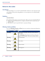
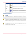
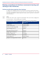
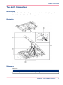
Océ User Manual
Two-Knife Booklet Trimmer-A1
Operating information
Copyright
Copyright 2011 by Canon Inc. All rights reserved.
No part of this publication may be reproduced or transmitted in any form or by any means,
electronic or mechanical, including photocopying and recording, or by any information
storage or retrieval system without the prior written permission of Canon Inc.
© 2011, Océ
All rights reserved. No part of this work may be reproduced, copied, adapted, or transmitted
in any form or by any means without written permission from Océ.
Océ makes no representation or warranties with respect to the contents hereof and specifically disclaims any implied warranties of merchantability or fitness for any particular purpose.
Furthermore, Océ reserves the right to revise this publication and to make changes from
time to time in the content hereof without obligation to notify any person of such revision
or changes.
Edition: 07-2011
Contents
Contents
Chapter 1
Preface.................................................................................................................5
Notes for the reader...................................................................................6
Naming conventions for finishers (commercial naming and naming in
User Interfaces)..........................................................................................8
Chapter 2
Parts and their functions....................................................................................9
Machine description.................................................................................10
Two-knife trim section.............................................................................11
Conveyor section......................................................................................13
Trim ejecting section................................................................................15
Chapter 3
Operating procedures.......................................................................................17
Turn the trimmer on.................................................................................18
Operation while trimming.......................................................................19
Remove or install the delivery tray.........................................................22
Chapter 4
Troubleshooting................................................................................................23
Error messages.........................................................................................24
Overview of possible errors....................................................................25
Clear a paper jam.....................................................................................27
Appendix A
Specifications....................................................................................................29
Specifications............................................................................................30
3
Contents
4
Chapter 1
Preface
Notes for the reader
Notes for the reader
Introduction
This manual helps you to use the Two-Knife Booklet Trimmer-A1. The manual contains
a description of the product and guidelines to use and operate the Two-Knife Booklet
Trimmer-A1.
Definition
Attention-Getters
Parts of this manual require your special attention. These parts can provide the following:
• Additional general information, for example, information that is useful when you
perform a task.
• Information to prevent personal injuries or property damage.
Warning, Caution and Note
The words Warning, Caution and Note draw your attention to important information.
Overview of the attention-getters#
Word
6
Icon
Indicates
Warning
Ignoring this warning could cause serious injury or
even death.
The Warning indication has several icons that warn
against various hazards. The icons are shown below.
Warning
General hazard
Warning
Hot surface
Warning
Electric shock
Warning
Moving parts
Chapter 1 - Preface
Notes for the reader
Word
Icon
Indicates
Warning
Laser beam
Caution
Ignoring this warning could cause injury or damage to
property.
Note
Indicates additional important information.
The use of heat-resistant gloves is mandatory when you
carry out these actions.
Important safety instructions
Warning:
Do not remove the safety covers or deactivate the sensor switches for the safety covers.
Otherwise, the machine may start suddenly without warning, leading to severe injury.
Warning:
When removing jammed booklets from the infeed section, do not put your hands and
fingers close to the belt. Otherwise, if the belt moves suddenly without warning, your
hands and fingers may be caught.
Warning:
This machine weighs 145 kg (319 lb). When you operate the machine, consider the machine weight and use the machine safely.
Chapter 1 - Preface
7
Naming conventions for finishers (commercial naming and naming in User Interfaces)
Naming conventions for finishers (commercial naming and
naming in User Interfaces)
Hardware and hardware naming in User Interfaces
To improve the readability of texts in User Interfaces of operator panels and software,
the finishers are generally referred to by their function. The table below shows the naming
conventions for finishers (commercial product names and the way these are referred to
in User Interfaces).
Note:
In some cases, there is only 1 name for several modules. The reason is that a configuration
can only contain 1 of the available types of modules.
Conversion table for commercial names versus user-friendly names in User Interfaces#
8
Commercial product name:
In UI, printer driver and software referred to as:
Finisher-AF1
'Stacker/stapler'
Saddle Finisher-AF2
'Stacker/stapler'
Puncher Unit-BP1/BQ1/BR1
'Puncher'
Paper Folding Unit-F1
'Folder'
Document Insertion Unit-F1
'Inserter'
High-Capacity Stacker-E1
'Stacker'
Booklet Trimmer-D1
'Trimmer'
Two-Knife Trimmer-A1
'Trimmer'
Perfect Binder-C1
'Perfect Binder'
Duplex Color Image Reader Unit-D1
'Scanner'
Chapter 1 - Preface
Chapter 2
Parts and their functions
Machine description
Machine description
Illustration
Main sections
Main sections#
10
Section
More information
1
Two-knife trim section
‘Two-knife trim section’ on page 11
2
Conveyor section
‘Conveyor section’ on page 13
3
Trim ejecting section
‘Trim ejecting section’ on page 15
Chapter 2 - Parts and their functions
Two-knife trim section
Two-knife trim section
Introduction
Each booklet delivered from the upstream trimmer is trimmed along it's top and bottom.
Then the booklet is delivered to the conveyor section.
Illustration
[11] Two-knife trim section
Main parts
Main parts#
A
Part
Function
Top cover
The top cover gives access to the trimmer.
Chapter 2 - Parts and their functions
11
Two-knife trim section
Part
Function
B
Handle
The handle lifts the booklet transport unit (TF2).
C
Booklet transport unit
(TF2)
If a booklet jam occurs in the two-knife trim section, you must press the handle and lift the booklet
transport unit (TF2) to remove the jammed
booklets.
How to open the booklet transport unit (TF2):
1. Press the handle to the left.
2. Lift the booklet transport unit (TF2) up.
D
Trim knives
The knives trim the top and bottom of each
booklet.
E
Transport belts
The transport belts move the booklets.
•Conveyor section, on page 13
•Trim ejecting section, on page 15
12
Chapter 2 - Parts and their functions
Conveyor section
Conveyor section
Introduction
The booklets delivered are laid out on the conveyor.
Illustration
[12] The conveyor section
Chapter 2 - Parts and their functions
13
Conveyor section
Main parts
Main parts#
Part
Function
A
Handle (TE)
Grip the handle and lift the roller unit when you
remove the booklets from the conveyor.
B
Delivery transport
rollers
The delivery transport rollers hold the finished
booklets. The position of the rollers is set automatically to match the booklet size.
C
Booklet detect sensor
The sensor detects when the conveyor is full of
stacked booklets.
D
Transport belts
The transport belts move the booklets after the
booklets were ejected.
E
Delivery tray
The delivery tray holds the stacked booklets. The
delivery tray can be removed.
Note:
When the delivery tray is removed, the
booklet detection sensor cannot detect
that the conveyor is full. Continuous operation is possible.
•Remove or install the delivery tray, on page 22
•Two-knife trim section, on page 11
•Trim ejecting section, on page 15
14
Chapter 2 - Parts and their functions
Trim ejecting section
Trim ejecting section
Introduction
The trim waste is ejected into the trimmer waste box through this section.
Illustration
[13] Trim ejecting section
Chapter 2 - Parts and their functions
15
Trim ejecting section
Main parts
Main parts#
Part
Function
A
Trim Full sensor
If trim waste is present between
the sensor and the reflector, the
operator panel displays the message 'Empty the two-knife trimmer waste box.'.
B
Delivery chute
Trim waste is ejected into the
trim box through this chute.
C
Trimmer waste box
The trimmer waste box contains
the trim waste.
•Two-knife trim section, on page 11
•Conveyor section, on page 13
16
Chapter 2 - Parts and their functions
Chapter 3
Operating procedures
Turn the trimmer on
Turn the trimmer on
How to turn on the trimmer
1. Put the On/Off button of Saddle Finisher-AF2 into the "I" position.
2. Press the On/Off button on top of the printer, next to the base of the operator panel.
Result
The trimmer will be turned on because the trimmer is connected to Saddle Finisher-AF2.
18
Chapter 3 - Operating procedures
Operation while trimming
Operation while trimming
Introduction
This section describes the main actions when using the trimmer.
Illustration
[14] Empty the delivery tray and the trimmer waste box
#
A
Delivery tray
B
Trim Full sensor
C
Trimmer waste box
Chapter 3 - Operating procedures
19
Operation while trimming
Empty the delivery tray
When the machine stops because the delivery tray is full, you must remove the booklets
from the delivery tray.
The machine will restart automatically.
Note:
When you remove the booklets before the delivery tray is full, you can increase the
productivity without interrupting the operation.
Note:
Be careful not to drop a booklet while removing it.
Empty the trimmer waste box
You must empty the trimmer waste box when:
• the machine stops and the operator panel displays the message 'Empty the two-knife
trimmer waste box.', and
• trim waste is present between the Trim Full sensor and the reflector.
The machine will restart automatically.
Note:
When you empty the trimmer waste box before the box is full, you can increase the
productivity without interrupting the operation.
Remove jammed booklets
When booklets jam, you must first open the top cover and the delivery section cover.
Then:
1. Press the handle of the transport unit.
2. Hold the handle and lift the transport unit up to remove the jammed booklets.
20
Chapter 3 - Operating procedures
Operation while trimming
[15] The covers of the trimmer
#
A
Top cover
B
Transport section
C
Delivery section cover
D
Opening the transport unit
Note:
If a booklet jam occurs frequently, refer to ‘Clear a paper jam’ on page 27 for instructions
on how to correct the problem.
Chapter 3 - Operating procedures
21
Remove or install the delivery tray
Remove or install the delivery tray
Illustration
[16] Remove the delivery tray
A. Locking knobs
B. Delivery tray
How to remove the delivery tray
1. To remove the delivery tray, loosen the 2 locking knobs.
2. Lift the delivery tray up to remove.
3. Tighten the two locking knobs.
How to install the delivery tray
1. To install the delivery tray, loosen the 2 locking knobs.
2. Lower the delivery tray to install.
3. Tighten the two locking knobs.
•Conveyor section, on page 13
22
Chapter 3 - Operating procedures
Chapter 4
Troubleshooting
Error messages
Error messages
Introduction
When an error occurs and the machine does not work properly, the operator panel will
display the message 'Call service.'. When this messages is displayed, keep in mind the
following cautions.
Warning:
Do not plug in or pull out the power plug with wet hands. This may cause an electrical
shock.
Warning:
When you pull the power plug out, be sure to hold the plug as you do so. If you pull it
out by the power cable, this may expose or cut the core wires and break the insulation,
which may result in fire or electrical shock.
'Call service.' message
When the operator panel displays the 'Call service.' message then:
• put the On/Off button of Saddle Finisher-AF2 into the "O" position.
• on the printer, touch 'System' -> 'Setup' -> 'Shut down system' to shut down the
printer correctly.
• wait for 10 seconds.
• turn on Saddle Finisher-AF2 and the printer again.
When the operator panel still displays the 'Call service.' message, then:
• turn off the main power.
• disconnect the power plug on the trimmer.
• contact your local authorized dealer.
When you contact your local authorized dealer, keep the following information at hand:
• product name.
• type of trouble.
• code number indicated on the operator panel of the printer.
24
Chapter 4 - Troubleshooting
Overview of possible errors
Overview of possible errors
Introduction
When an error occurs in the trimmer, the printer operator panel displays a corresponding
message. The table below describes possible solutions for trimmer-related errors.
Illustration
[17] Error locations
Possible errors
Errors and solutions#
Cause of error
Solution
The top cover is open.
Close the top cover (1).
The delivery tray is full.*
Lift the E handle and remove the
booklets from the conveyor section.
The trimmer waste box is full.
Empty the trimmer waste box. If any trim
waste is left in the delivery chute, then
remove the trim waste.
Chapter 4 - Troubleshooting
25
Overview of possible errors
Cause of error
Solution
A booklet jam has occurred at the entrance of the two-knife trim section.
• Open the delivery section cover (2) of
the upstream trimmer.
• Open the top cover (1).
• Open the A and F2 transport unit,
and remove the jammed booklet.
• Reposition the A and F2 transport
unit, and close the top cover (1) and
the delivery section cover (2) to restart
the printing.
A booklet jam has occurred in the twoknife trim section.
• Open the top cover (1).
• Open the F2 transport unit and re-
move the jammed booklet.
• Reposition the F2 transport unit and
close the top cover (1) to restart the
printing.
A booklet jam has occurred at the exit of
the two-knife trim section.
• Open the top cover (1).
• Open the F2 transport unit and re-
move the jammed booklet.
• If necessary, also hold the E handle
and lift the conveyor.
• Reposition the E and F2 transport
unit, and close the top cover (1)) to
restart printing.
* If the operator panel displays the message 'Empty the two-knife trimmer waste box.'
while the delivery tray is not full, then trim waste may block the sensor.
26
Chapter 4 - Troubleshooting
Clear a paper jam
Clear a paper jam
Introduction
Paper jams can occur at the following locations:
#
A
Conveyor section
B
Trim section
When a paper jam occurs, the jam is always caused by a paper chip jam or dirty transport
belts. The table below describes these causes and the solutions.
Illustration
[18] Clear a paper jam
Chapter 4 - Troubleshooting
27
Clear a paper jam
How to clear a paper jam
#
Cause of jam
Solution
Paper chip jam
• Open the transport unit.
• Check if any paper chips are left on
the booklet feed path.
• Remove the paper chips.
Transport belts are dirty
28
Chapter 4 - Troubleshooting
Clean the transport belts. Contact your
local authorized dealer.
Appendix A
Specifications
Specifications
Specifications
Two-Knife Booklet Trimmer-A1
Note:
Whenever a number of sheets is mentioned in the table below, the figure is based on
media of 80 g/m² (20 lb Bond).
Specifications of Two-Knife Booklet Trimmer-A1#
Item
Specifications
Description
Top-bottom trimmer
Maximum number of sheets
trimmable
50 sheets or 48 sheets + 2 sheets of 300 g/m² (110
lb Cover)
Note:
To prevent damage to cover sheets, it is
recommended to use thicker sheets for
covers than the other sheets in booklets.
Possible trim size (before halffolding)
A3, B4, A4R, 330.2 mm x 487.7 mm (13"x19.2"),
12"x18", 11"x17", Legal, LetterR, 320 mm x 450
mm[SRA3](12.60" x 17.72").
Note:
The possible trim size can change, depending on the connected printer.
30
Possible trim width
Top-bottom: 2 to 15 mm (0.08" to 0.59").
The top-bottom length after trimming must be at
least 190 mm (7.48").
Trimmer waste box capacity
Trimmed at top AND bottom: trim strips of +/750 sheets.
Trimmed at top OR bottom: trim strips of +/1,500 sheets.
Appendix A - Specifications
Specifications
Item
Specifications
Conveyor capacity
30 booklets containing 40 sheets of A4 / Letter
when trimming 20 mm (0.79") of width in
Booklet Trimmer-D1.
Note:
When the delivery tray is removed, the
conveyor full condition is not detected.
Continuous operation is possible.
Machine dimensions (without
conveyor section and delivery
tray)
WxDxH: 536 mm x 770 mm x 1,040 mm (21"
x 30.5" x 41")
Machine weight (without conveyor section and delivery tray)
Approximately 145 kg (319 lb)
Voltage
220-240 V AC, 50/60 Hz, 2.3 A
Power consumption
440 W or less
Noise level
70 dBA or less
Temperature in use
Compliant with the specification of the printer
Temperature in storage
-10 to +40 °C (14 to 104 °F)
Temperature in transportation
-10 to +50 °C (14 to 122 °F)
Humidity
Compliant with the specification of the printer
Pressure
608 to 1,013 hPa
Contamination level
Pollution Degree 2 (Office environment)
Appendix A - Specifications
31
Index
Index
T
Clear
Paper chip jam ................................................27
Paper jam .......................................................27
Conversion table for commercial names and user
interface names
Conversion table for commercial names and user
interface names .................................................8
Conveyor section
Conveyor section ............................................13
D
Delivery tray
Install .............................................................22
Remove ..........................................................22
E
Error messages
Error messages ................................................24
Errors and solutions
Errors and solutions ........................................25
H
Hardware naming in User Interfaces
Hardware naming in User Interfaces .................8
I
Install the delivery tray
Install the delivery tray ....................................22
M
Machine description
Machine description .......................................10
R
Remove the delivery tray
Remove the delivery tray .................................22
32
Trim ejecting section
Trim ejecting section ......................................15
Two-knife trim section
Two-knife trim section ...................................11