1
SERVICE MANUAL
Theory of Operation
501/421/361
2009.03
Ver. 2.0
THEORY OF OPERATION TOTAL CONTENTS
SAFETY AND IMPORTANT WARNING ITEMS ..............................................................S-1
IMPORTANT NOTICE ................................................................................................S-1
DESCRIPTION ITEMS FOR DANGER, WARNING AND CAUTION .........................S-1
SAFETY WARNINGS .................................................................................................S-2
SAFETY INFORMATION ...............................................................................................S-13
IMPORTANT NOTICE ..............................................................................................S-13
INDICATION OF WARNING ON THE MACHINE .....................................................S-14
MEASURES TO TAKE IN CASE OF AN ACCIDENT ....................................................S-16
Legal restrictions on copying .......................................................................................... C-1
Composition of the service manual ................................................................................. C-2
Notation of the service manual ....................................................................................... C-3
bizhub 501/421/361 Main Body
OUTLINE ........................................................................................................................ 1
COMPOSITION/OPERATION ...................................................................................... 11
* For particulars, see the contents of the main body.
DF-613
OUTLINE ....................................................................................................................... 1
COMPOSITION/OPERATION ........................................................................................ 5
* For particulars, see the contents of DF-613.
PC-206
OUTLINE ....................................................................................................................... 1
COMPOSITION/OPERATION ........................................................................................ 3
* For particulars, see the contents of PC-206.
PC-407
OUTLINE ....................................................................................................................... 1
COMPOSITION/OPERATION ........................................................................................ 3
* For particulars, see the contents of PC-407.
LU-203
OUTLINE ........................................................................................................................ 1
COMPOSITION/OPERATION ........................................................................................ 3
* For particulars, see the contents of LU-203.
i
FS-522/PU-501/OT-602
OUTLINE ....................................................................................................................... 1
COMPOSITION/OPERATION ....................................................................................... 9
* For particulars, see the contents of FS-522/PU-501/OT-602.
FS-523/RU-507
OUTLINE ........................................................................................................................ 1
COMPOSITION/OPERATION........................................................................................ 7
* For particulars, see the contents of FS-523/RU-507.
SD-507
OUTLINE ....................................................................................................................... 1
COMPOSITION/OPERATION ....................................................................................... 3
* For particulars, see the contents of SD-507.
MT-502
OUTLINE ....................................................................................................................... 1
COMPOSITION/OPERATION ....................................................................................... 3
* For particulars, see the contents of MT-502.
JS-502
OUTLINE ....................................................................................................................... 1
COMPOSITION/OPERATION ....................................................................................... 3
* For particulars, see the contents of JS-502.
ii
SAFETY AND IMPORTANT WARNING ITEMS
SAFETY AND IMPORTANT WARNING ITEMS
Read carefully the Safety and Important Warning Items described below to understand
them before doing service work.
IMPORTANT NOTICE
Because of possible hazards to an inexperienced person servicing this product as well as
the risk of damage to the product, Konica Minolta Business Technologies, INC. (hereafter
called the KMBT) strongly recommends that all servicing be performed only by KMBTtrained service technicians.
Changes may have been made to this product to improve its performance after this Service
Manual was printed. Accordingly, KMBT does not warrant, either explicitly or implicitly, that
the information contained in this Service Manual is complete and accurate.
The user of this Service Manual must assume all risks of personal injury and/or damage to
the product while servicing the product for which this Service Manual is intended.
Therefore, this Service Manual must be carefully read before doing service work both in the
course of technical training and even after that, for performing maintenance and control of
the product properly.
Keep this Service Manual also for future service.
DESCRIPTION ITEMS FOR DANGER,
WARNING AND CAUTION
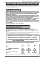
In this Service Manual, each of three expressions " DANGER", " WARNING", and
" CAUTION" is defined as follows together with a symbol mark to be used in a limited
meaning.
When servicing the product, the relevant works (disassembling, reassembling, adjustment,
repair, maintenance, etc.) need to be conducted with utmost care.
DANGER: Action having a high possibility of suffering death or serious injury
WARNING: Action having a possibility of suffering death or serious injury
CAUTION: Action having a possibility of suffering a slight wound, medium
trouble and property damage
Symbols used for safety and important warning items are defined as follows:
:Precaution when using the
copier.
:Prohibition when using the
copier.
:Direction when using the
copier.
General
precaution
Electric hazard
High
temperature
General
prohibition
Do not touch
with wet hand
Do not
disassemble
General
instruction
Unplug
Ground/Earth
S-1
SAFETY AND IMPORTANT WARNING ITEMS
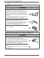
SAFETY WARNINGS
[1] MODIFICATIONS NOT AUTHORIZED BY KONICA MINOLTA
BUSINESS TECHNOLOGIES, INC.
Konica Minolta brand products are renowned for their high reliability. This reliability is
achieved through high-quality design and a solid service network.
Product design is a highly complicated and delicate process where numerous mechanical,
physical, and electrical aspects have to be taken into consideration, with the aim of arriving
at proper tolerances and safety factors. For this reason, unauthorized modifications involve
a high risk of degradation in performance and safety. Such modifications are therefore
strictly prohibited. The points listed below are not exhaustive, but they illustrate the reasoning behind this policy.
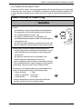
Prohibited Actions
DANGER
• Using any cables or power cord not specified by KMBT.
• Using any fuse or thermostat not specified by KMBT.
Safety will not be assured, leading to a risk of fire and
injury.
• Disabling fuse functions or bridging fuse terminals with
wire, metal clips, solder or similar object.
• Disabling relay functions (such as wedging paper between
relay contacts)
• Disabling safety functions (interlocks, safety circuits, etc.)
Safety will not be assured, leading to a risk of fire and
injury.
• Making any modification to the product unless instructed
by KMBT
• Using parts not specified by KMBT
S-2
SAFETY AND IMPORTANT WARNING ITEMS
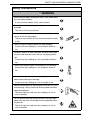
[2] POWER PLUG SELECTION
In some countries or areas, the power plug provided with the product may not fit wall outlet
used in the area. In that case, it is obligation of customer engineer (hereafter called the CE)
to attach appropriate power plug or power cord set in order to connect the product to the
supply.
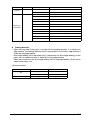
Power Cord Set or Power Plug
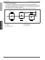
WARNING
• Use power supply cord set which meets the following
criteria:
- provided with a plug having configuration intended for
the connection to wall outlet appropriate for the product's rated voltage and current, and
AC230V
- the plug has pin/terminal(s) for grounding, and
- provided with three-conductor cable having enough current capacity, and
- the cord set meets regulatory requirements for the area.
AC208V
240V
Use of inadequate cord set leads to fire or electric shock.
• Attach power plug which meets the following criteria:
- having configuration intended for the connection to wall
outlet appropriate for the product's rated voltage and
current, and
- the plug has pin/terminal(s) for grounding, and
- meets regulatory requirements for the area.
Use of inadequate cord set leads to the product connecting to inadequate power supply (voltage, current capacity,
grounding), and may result in fire or electric shock.
• Conductors in the power cable must be connected to terminals of the plug according to the following order:
• Black or Brown:
L (line)
• White or Light Blue:
N (neutral)
• Green/Yellow:
PE (earth)
Wrong connection may cancel safeguards within the
product, and results in fire or electric shock.
S-3
SAFETY AND IMPORTANT WARNING ITEMS
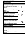
[3] CHECKPOINTS WHEN PERFORMING ON-SITE SERVICE
Konica Minolta brand products are extensively tested before shipping, to ensure that all
applicable safety standards are met, in order to protect the customer and CE from the risk
of injury. However, in daily use, any electrical equipment may be subject to parts wear and
eventual failure. In order to maintain safety and reliability, the CE must perform regular
safety checks.
1.
Power Supply
Connection to Power Supply
WARNING
• Check that mains voltage is as specified.
Connection to wrong voltage supply may result in fire or
electric shock.
?V
• Connect power plug directly into wall outlet having same
configuration as the plug.
Use of an adapter leads to the product connecting to
inadequate power supply (voltage, current capacity,
grounding), and may result in fire or electric shock.
If proper wall outlet is not available, advice the customer
to contact qualified electrician for the installation.
• Plug the power cord into the dedicated wall outlet with a
capacity greater than the maximum power consumption.
If excessive current flows in the wall outlet, fire may
result.
• If two or more power cords can be plugged into the wall
outlet, the total load must not exceed the rating of the wall
outlet.
If excessive current flows in the wall outlet, fire may
result.
• Make sure the power cord is plugged in the wall outlet
securely.
Contact problems may lead to increased resistance,
overheating, and the risk of fire.
S-4
kw
SAFETY AND IMPORTANT WARNING ITEMS
Connection to Power Supply
WARNING
• Check whether the product is grounded properly.
If current leakage occurs in an ungrounded product, you
may suffer electric shock while operating the product.
Connect power plug to grounded wall outlet.
Power Plug and Cord
WARNING
• When using the power cord set (inlet type) that came with
this product, make sure the connector is securely inserted
in the inlet of the product.
When securing measure is provided, secure the cord with
the fixture properly.
If the power cord (inlet type) is not connected to the product securely, a contact problem may lead to increased
resistance, overheating, and risk of fire.
• Check whether the power cord is not stepped on or
pinched by a table and so on.
Overheating may occur there, leading to a risk of fire.
• Check whether the power cord is damaged. Check
whether the sheath is damaged.
If the power plug, cord, or sheath is damaged, replace
with a new power cord or cord set (with plug and connector on each end) specified by KMBT.
Using the damaged power cord may result in fire or electric shock.
• Do not bundle or tie the power cord.
Overheating may occur there, leading to a risk of fire.
S-5
SAFETY AND IMPORTANT WARNING ITEMS
Power Plug and Cord
WARNING
• Check whether dust is collected around the power plug
and wall outlet.
Using the power plug and wall outlet without removing
dust may result in fire.
• Do not insert the power plug into the wall outlet with a wet
hand.
The risk of electric shock exists.
• When unplugging the power cord, grasp the plug, not the
cable.
The cable may be broken, leading to a risk of fire and
electric shock.
Wiring
WARNING
• Never use multi-plug adapters to plug multiple power cords
in the same outlet.
If used, the risk of fire exists.
• When an extension cord is required, use a specified one.
Current that can flow in the extension cord is limited, so
using a too long extension cord may result in fire.
Do not use an extension cable reel with the cable taken
up. Fire may result.
S-6
SAFETY AND IMPORTANT WARNING ITEMS
2.
Installation Requirements
Prohibited Installation Places
WARNING
• Do not place the product near flammable materials or volatile materials that may catch fire.
A risk of fire exists.
• Do not place the product in a place exposed to water such
as rain.
A risk of fire and electric shock exists.
When not Using the Product for a long time
WARNING
• When the product is not used over an extended period of
time (holidays, etc.), switch it off and unplug the power
cord.
Dust collected around the power plug and outlet may
cause fire.
Ventilation
CAUTION
• The product generates ozone gas during operation, but it
will not be harmful to the human body.
If a bad smell of ozone is present in the following cases,
ventilate the room.
a. When the product is used in a poorly ventilated room
b. When taking a lot of copies
c. When using multiple products at the same time
Fixing
CAUTION
• Be sure to lock the caster stoppers.
In the case of an earthquake and so on, the product may
slide, leading to a injury.
S-7
SAFETY AND IMPORTANT WARNING ITEMS
3.
Servicing
Inspection before Servicing
CAUTION
• Before conducting an inspection, read all relevant documentation (service manual, technical notices, etc.) and
proceed with the inspection following the prescribed procedure in safety clothes, using only the prescribed tools.
Do not make any adjustment not described in the documentation.
If the prescribed procedure or tool is not used, the product may break and a risk of injury or fire exists.
• Before conducting an inspection, be sure to disconnect
the power plugs from the product and options.
When the power plug is inserted in the wall outlet, some
units are still powered even if the POWER switch is
turned OFF. A risk of electric shock exists.
• The area around the fixing unit is hot.
You may get burnt.
Work Performed with the Product Powered On
WARNING
• Take every care when making adjustments or performing
an operation check with the product powered.
If you make adjustments or perform an operation check
with the external cover detached, you may touch live or
high-voltage parts or you may be caught in moving gears
or the timing belt, leading to a risk of injury.
• Take every care when servicing with the external cover
detached.
High-voltage exists around the drum unit. A risk of electric shock exists.
S-8
SAFETY AND IMPORTANT WARNING ITEMS
Safety Checkpoints
WARNING
• When taking a report of problems from a user, check each
part and repair properly.
A risk of product trouble, injury, and fire exists.
• Check the exterior and frame for edges, burrs, and other
damages.
The user or CE may be injured.
• Do not allow any metal parts such as clips, staples, and
screws to fall into the product.
They can short internal circuits and cause electric shock
or fire.
• Check wiring for squeezing and any other damage.
Current can leak, leading to a risk of electric shock or
fire.
• Carefully remove all toner remnants and dust from electrical parts and electrode units such as a charging corona
unit.
Current can leak, leading to a risk of product trouble or
fire.
• Check high-voltage cables and sheaths for any damage.
Current can leak, leading to a risk of electric shock or
fire.
• Check electrode units such as a charging corona unit for
deterioration and sign of leakage.
Current can leak, leading to a risk of trouble or fire.
• Before disassembling or adjusting the write unit (P/H unit)
incorporating a laser, make sure that the power cord has
been disconnected.
The laser light can enter your eye, leading to a risk of
loss of eyesight.
• Do not remove the cover of the write unit. Do not supply
power with the write unit shifted from the specified mounting position.
The laser light can enter your eye, leading to a risk of
loss of eyesight.
S-9
SAFETY AND IMPORTANT WARNING ITEMS
Safety Checkpoints
WARNING
• When replacing a lithium battery, replace it with a new lithium battery specified in the Parts Guide Manual. Dispose
of the used lithium battery using the method specified by
local authority.
Improper replacement can cause explosion.
• After replacing a part to which AC voltage is applied (e.g.,
optical lamp and fixing lamp), be sure to check the installation state.
A risk of fire exists.
• Check the interlock switch and actuator for loosening and
check whether the interlock functions properly.
If the interlock does not function, you may receive an
electric shock or be injured when you insert your hand in
the product (e.g., for clearing paper jam).
• Make sure the wiring cannot come into contact with sharp
edges, burrs, or other pointed parts.
Current can leak, leading to a risk of electric shock or
fire.
• Make sure that all screws, components, wiring, connectors, etc. that were removed for safety check and maintenance have been reinstalled in the original location. (Pay
special attention to forgotten connectors, pinched cables,
forgotten screws, etc.)
A risk of product trouble, electric shock, and fire exists.
Handling of Consumables
WARNING
• Toner and developer are not harmful substances, but care
must be taken not to breathe excessive amounts or let the
substances come into contact with eyes, etc. It may be
stimulative.
If the substances get in the eye, rinse with plenty of water
immediately. When symptoms are noticeable, consult a
physician.
S-10
SAFETY AND IMPORTANT WARNING ITEMS
Handling of Consumables
WARNING
• Never throw the used cartridge and toner into fire.
You may be burned due to dust explosion.
Handling of Service Materials
CAUTION
• Unplug the power cord from the wall outlet.
Isopropyl alcohol and acetone are highly flammable and
must be handled with care. A risk of fire exists.
• Do not replace the cover or turn the product ON before
any solvent remnants on the cleaned parts have fully
evaporated.
A risk of fire exists.
• Use only a small amount of cleaner at a time and take
care not to spill any liquid. If this happens, immediately
wipe it off.
A risk of fire exists.
• When using any solvent, ventilate the room well.
Breathing large quantities of organic solvents can lead to
discomfort.
4.
Fuse
Fuse
CAUTION
• CAUTION
Double pole / neutral fusing
• ATTENTION
Double pôle / Fusible sur le neutre
S-11
SAFETY AND IMPORTANT WARNING ITEMS
5.
Used Batteries Precautions
Handling of batteries
CAUTION
• ALL Areas
CAUTION
Danger of explosion if battery is incorrectly replaced.
Replace only with the same or equivalent type recommended by the manufacturer.
Dispose of used batteries according to the manufacturer’s instructions.
• Germany
VORSICHT!
Explosionsgefahr bei unsachgemäßem Austausch der Batterie.
Ersatz nur durch denselben oder einen vom Hersteller empfohlenen gleichwertigen Typ.
Entsorgung gebrauchter Batterien nach Angaben des Herstellers.
• France
ATTENTION
Il y a danger d’explosion s’il y a remplacement incorrect de la batterie.
Remplacer uniquement avec une batterie du même type ou d’un type équivalent recommandé par le constructeur.
Mettre au rebut les batteries usagées conformément aux instructions du fabricant.
• Denmark
ADVARSEL!
Lithiumbatteri - Eksplosionsfare ved fejlagtig håndtering.
Udskiftning må kun ske med batteri af samme fabrikat og type.
Levér det brugte batteri tilbage til leverandøren.
• Finland, Sweden
VAROlTUS
Paristo voi räjähtää, jos se on virheellisesti asennettu.
Vaihda paristo ainoastaan laitevalmistajan suosittelemaan tyyppiin.
Hävitä käytetty paristo valmistajan ohjeiden mukaisesti.
VARNING
Explosionsfara vid felaktigt batteribyte.
Använd samma batterityp eller en ekvivalent typ som rekommenderas av apparattillverkaren.
Kassera använt batteri enligt fabrikantens instruktion.
• Norway
ADVARSEL
Eksplosjonsfare ved feilaktig skifte av batteri.
Benytt samme batteritype eller en tilsvarende type anbefalt av apparatfabrikanten.
Brukte batterier kasseres i henhold til fabrikantens instruksjoner.
S-12
SAFETY INFORMATION
SAFETY INFORMATION
IMPORTANT NOTICE
The Center for Devices and Radiological Health (CDRH) of the U.S. Food and Drug Administration implemented regulations for laser products manufactured since August 1, 1976.
Compliance is mandatory for products marketed in the United States.
This copier is certified as a "Class 1" laser product under the U.S.
Department of Health and Human Services (DHHS) Radiation Performance Standard
according to the Radiation Control for Health and Safety Act of 1968. Since radiation emitted inside this copier is completely confined within protective housings and external covers,
the laser beam cannot escape during any phase of normal user operation.
S-13
SAFETY INFORMATION
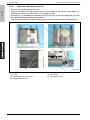
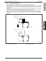
INDICATION OF WARNING ON THE MACHINE
Caution labels shown below are attached in some areas on/in the machine.
When accessing these areas for maintenance, repair, or adjustment, special care should
be taken to avoid burns and electric shock.
Finisher FS-522
50gap0e001nb
S-14
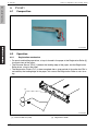
SAFETY INFORMATION
FS-523
50gap0e002nb
CAUTION:
• You may be burned or injured if you touch any area that you are advised by any
caution label to keep yourself away from. Do not remove caution labels. And also,
when the caution label is peeled off or soiled and cannot be seen clearly, replace
it with a new caution label.
S-15
MEASURES TO TAKE IN CASE OF AN ACCIDENT
MEASURES TO TAKE IN CASE OF
AN ACCIDENT
1. If an accident has occurred, the distributor who has been notified first must immediately
take emergency measures to provide relief to affected persons and to prevent further
damage.
2. If a report of a serious accident has been received from a customer, an on-site evaluation must be carried out quickly and KMBT must be notified.
3. To determine the cause of the accident, conditions and materials must be recorded
through direct on-site checks, in accordance with instructions issued by KMBT.
4. For reports and measures concerning serious accidents, follow the regulations specified by every distributor.
S-16
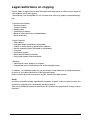
Legal restrictions on copying
Certain types of originals must never be copied with the purpose or intent to pass copies of
such originals off as the originals.
The following is not a complete list, but is meant to be used as a guide to responsible copying.
<Financial Instruments>
•
•
•
•
•
•
Personal checks
Traveler’s checks
Money orders
Certificates of deposit
Bonds or other certificates of indebtedness
Stock certificates
<Legal Originals>
•
•
•
•
•
•
•
•
Food stamps
Postage stamps (canceled or uncanceled)
Checks or drafts drawn by government agencies
Internal revenue stamps (canceled or uncanceled)
Passports
Immigration papers
Motor vehicle licenses and titles
House and property titles and deeds
<General>
• Identification cards, badges, or insignias
• Copyrighted works without permission of the copyright owner
In addition, it is prohibited under any circumstances to copy domestic or foreign currencies,
or works of art without permission of the copyright owner.
When in doubt about the nature of an original, consult with legal counsel.
Detail
In order to prohibit the illegal reproduction of certain originals, such as paper currency, this
machine is equipped with a counterfeit prevention feature.
Due to the counterfeit prevention feature that this machine is equipped with, images may be
distorted.
C-1
Composition of the service manual
This service manual consists of the following sections and chapters:
<Theory of Operation section>
OUTLINE:
System configuration, product specifications,
unit configuration, and paper path
COMPOSITION/OPERATION: Configuration of each unit, explanation of the operating
system, and explanation of the control system
This section gives, as information for the CE to get a full understanding of the product, a
rough outline of the object and role of each function, the relationship between the electrical
system and the mechanical system, and the timing of operation of each part.
<Field service section>
OUTLINE:
System configuration, and product specifications
MAINTENANCE:
Service schedule *, maintenance steps,
list of service tools and directions for use *,
firmware version up method *,
and removal/reinstallation methods of major parts
ADJUSTMENT/SETTING:
Utility mode *, service mode *, security and mechanical
adjustment
TROUBLESHOOTING*:
List of jam codes, their causes, operation when a jam
occurs and its release method, and list of error codes,
their causes, operation when a warning is issued and estimated abnormal parts.
APPENDIX*:
Parts layout drawings, connector layout drawings, timing
chart, overall layout drawing
This section gives, as information required by the CE at the site (or at the customer's
premise), a rough outline of the service schedule and its details, maintenance steps, the
object and role of each adjustment, error codes and supplementary information.
The details of items with an asterisk "*" are described only in the service manual of
the main body.
C-2
Notation of the service manual
A. Product name
In this manual, each of the products is described as follows:
(1) IC board:
Standard printer
(2) bizhub 501/421/361:
Main body
(3) Microsoft Windows 95:
Windows 95
Microsoft Windows 98:
Windows 98
Microsoft Windows Me:
Windows Me
Microsoft Windows NT 4.0:
Windows NT 4.0 or Windows NT
Microsoft Windows 2000:
Windows 2000
Microsoft Windows XP:
Windows XP
Microsoft Windows Vista:
Windows Vista
When the description is made in combination of the OS's mentioned above:
Windows 95/98/Me
Windows NT 4.0/2000
Windows NT/2000/XP
Windows 95/98/Me/NT/2000/XP
B. Brand name
The company names and product names mentioned in this manual are the brand name or
the registered trademark of each company.
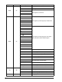
C. Electrical parts and signals
Those listed by way of example below are not exhaustive, but only some instances among
many.
Classification Load symbol
Ex. of signal name
Description
IN
PS
Sensor
PS
Door PS1
Sensor detection signal
SIG
102 PS
24V
Solenoid
SD
DRV
SOL
24V
Clutch
CL
DRV
SOL
Power to drive the solenoid
Drive signal
Power to drive the clutch
Drive signal
C-3
Classification Load symbol
Motor
M
Ex. of signal name
Description
24V
Power to drive the motor
CONT
Drive signal
DRV1
DRV2
D1
Drive signals of two kinds
D2
_U
_V
_W
DRV1
Drive signals (control signals) of three kinds
DRV2
DRV3
D1
D2
D3
D4
DRV A
DRV A
DRV B
DRV B
Drive signals (control signals) of four kinds
Motor, phases A and B control signals
A
Motor
M
/A
B
/B
AB
BB
CLK, PLL
PLL control signal
LCK, Lock, LD
PLL lock signal
FR
Forward/reverse rotation signal
EM, Lock, LCK, LD
Motor lock abnormality
BLK
Drive brake signal
P/S
Power/stop
S/S
SS
Fan
Others
C-4
FM
Operating load start/stop signal
CW/CCW, F/R
Rotational direction switching signal
ENB
Effective signal
TEMP_ER
Motor temperature abnormality detection signal
24V
Power to drive the fan motor
CONT, DRIVE
Drive signal
HL
Speed control signal (2 speeds)
EM, Lock, LCK, FEM
Detection signal
TH1.S, ANG
Analog signal
Classification Load symbol
Ground
Serial communication
Ex. of signal name
Description
SG, S.GND, S_GND
Signal ground
PG, P.GND
Power ground
DCD
Data carrier detection
SIN
Serial input
SOUT
Serial output
DTR
Data terminal operation available
GND
Signal ground (earth)
DSR, DSET
Data set ready
RTS
Transmission request signal
CTS
Consent transmission signal
RI
Ring indicator
TXD
Serial transmission data
RXD
Serial reception data
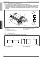
D. Feeding direction
• When the long side of the paper is parallel with the feeding direction, it is called short
edge feeding. The feeding direction which is perpendicular to the short edge feeding is
called the long edge feeding.
• Short edge feeding will be identified with [S (abbreviation for Short edge feeding)] on the
paper size. No specific notation is added for the long edge feeding.
When the size has only the short edge feeding with no long edge feeding, [S] will not be
added to the paper size.
<Sample notation>
Paper size
A4
A3
Feeding direction
Notation
Long edge feeding
A4
Short edge feeding
A4S
Short edge feeding
A3
C-5
Blank Page
C-6
SERVICE MANUAL
Theory of Operation
501/421/361
Main body
2009.03
Ver. 2.0
Revision history
After publication of this service manual, the parts and mechanism may be subject to change for
improvement of their performance.
Therefore, the descriptions given in this service manual may not coincide with the actual machine.
When any change has been made to the descriptions in the service manual, a revised version will be
issued with a revision mark added as required.
Revision mark:
• To indicate clearly a section revised, 1 is shown at the left margin of the revised section.
The number inside 1 represents the number of times the revision has been made.
• To indicate clearly a page that contains the revision, 1 is shown near the page number of the
corresponding page.
The number inside 1 represents the number of times the revision has been made.
NOTE
Revision marks shown in a page are restricted only to the latest ones with the old ones deleted.
• When a page revised in Ver. 2.0 has been changed in Ver. 3.0:
The revision marks for Ver. 3.0 only are shown with those for Ver. 2.0 deleted.
• When a page revised in Ver. 2.0 has not been changed in Ver. 3.0:
The revision marks for Ver. 2.0 are left as they are.
2009/03
2.0
1.0
1
—
Revision due to the addition of a new optional unit (LK)
2008/05
Date
Service manual Ver.
Revision mark
Descriptions of revision
Issue of the first edition
Theory of Operation Ver.2.0 Mar. 2009
CONTENTS
bizhub 501/421/361
CONTENTS
bizhub 501/421/361
OUTLINE
1. SYSTEM CONFIGURATION . . . . . . . . . . . . . . . . . . . . . . . . . . . . . . . . . . . . . . . . . . . . . . . . . . . . . . . . . . . . 1
2. PRODUCT SPECIFICATIONS. . . . . . . . . . . . . . . . . . . . . . . . . . . . . . . . . . . . . . . . . . . . . . . . . . . . . . . . . . . 4
3. UNIT CONFIGURATION . . . . . . . . . . . . . . . . . . . . . . . . . . . . . . . . . . . . . . . . . . . . . . . . . . . . . . . . . . . . . . . 8
4. PAPER PATH . . . . . . . . . . . . . . . . . . . . . . . . . . . . . . . . . . . . . . . . . . . . . . . . . . . . . . . . . . . . . . . . . . . . . . . 9
COMPOSITION/OPERATION
5. OVERALL CONFIGURATION . . . . . . . . . . . . . . . . . . . . . . . . . . . . . . . . . . . . . . . . . . . . . . . . . . . . . . . . . . 11
5.1
Time chart when the power is turned ON . . . . . . . . . . . . . . . . . . . . . . . . . . . . . . . . . . . . . . . . . . . . . 11
5.2
Control block diagram. . . . . . . . . . . . . . . . . . . . . . . . . . . . . . . . . . . . . . . . . . . . . . . . . . . . . . . . . . . . 12
6. SCANNER SECTION . . . . . . . . . . . . . . . . . . . . . . . . . . . . . . . . . . . . . . . . . . . . . . . . . . . . . . . . . . . . . . . . 13
6.1
Composition . . . . . . . . . . . . . . . . . . . . . . . . . . . . . . . . . . . . . . . . . . . . . . . . . . . . . . . . . . . . . . . . . . . 13
6.2
Drive . . . . . . . . . . . . . . . . . . . . . . . . . . . . . . . . . . . . . . . . . . . . . . . . . . . . . . . . . . . . . . . . . . . . . . . . . 13
6.3
Operation . . . . . . . . . . . . . . . . . . . . . . . . . . . . . . . . . . . . . . . . . . . . . . . . . . . . . . . . . . . . . . . . . . . . . 14
6.3.1
Scan/exposure lamp control . . . . . . . . . . . . . . . . . . . . . . . . . . . . . . . . . . . . . . . . . . . . . . . . . . 14
6.3.2
Original size detection control. . . . . . . . . . . . . . . . . . . . . . . . . . . . . . . . . . . . . . . . . . . . . . . . . . 17
6.3.3
AE control . . . . . . . . . . . . . . . . . . . . . . . . . . . . . . . . . . . . . . . . . . . . . . . . . . . . . . . . . . . . . . . . 18
6.3.4
Image processing. . . . . . . . . . . . . . . . . . . . . . . . . . . . . . . . . . . . . . . . . . . . . . . . . . . . . . . . . . . 19
7. WRITE SECTION . . . . . . . . . . . . . . . . . . . . . . . . . . . . . . . . . . . . . . . . . . . . . . . . . . . . . . . . . . . . . . . . . . . 20
7.1
Composition . . . . . . . . . . . . . . . . . . . . . . . . . . . . . . . . . . . . . . . . . . . . . . . . . . . . . . . . . . . . . . . . . . . 20
7.2
Operation . . . . . . . . . . . . . . . . . . . . . . . . . . . . . . . . . . . . . . . . . . . . . . . . . . . . . . . . . . . . . . . . . . . . . 21
7.2.1
Laser beam path . . . . . . . . . . . . . . . . . . . . . . . . . . . . . . . . . . . . . . . . . . . . . . . . . . . . . . . . . . . 21
7.2.2
Write control . . . . . . . . . . . . . . . . . . . . . . . . . . . . . . . . . . . . . . . . . . . . . . . . . . . . . . . . . . . . . . 21
7.2.3
Image stabilization control . . . . . . . . . . . . . . . . . . . . . . . . . . . . . . . . . . . . . . . . . . . . . . . . . . . . 21
7.2.4
Image processing. . . . . . . . . . . . . . . . . . . . . . . . . . . . . . . . . . . . . . . . . . . . . . . . . . . . . . . . . . . 22
8. PHOTO CONDUCTOR SECTION . . . . . . . . . . . . . . . . . . . . . . . . . . . . . . . . . . . . . . . . . . . . . . . . . . . . . . . 23
8.1
8.2
8.3
Composition . . . . . . . . . . . . . . . . . . . . . . . . . . . . . . . . . . . . . . . . . . . . . . . . . . . . . . . . . . . . . . . . . . . 23
Drive . . . . . . . . . . . . . . . . . . . . . . . . . . . . . . . . . . . . . . . . . . . . . . . . . . . . . . . . . . . . . . . . . . . . . . . . . 24
8.2.1
Drum drive . . . . . . . . . . . . . . . . . . . . . . . . . . . . . . . . . . . . . . . . . . . . . . . . . . . . . . . . . . . . . . . . 24
8.2.2
Drum claw drive . . . . . . . . . . . . . . . . . . . . . . . . . . . . . . . . . . . . . . . . . . . . . . . . . . . . . . . . . . . . 24
Operation . . . . . . . . . . . . . . . . . . . . . . . . . . . . . . . . . . . . . . . . . . . . . . . . . . . . . . . . . . . . . . . . . . . . . 25
8.3.1
Image creation control . . . . . . . . . . . . . . . . . . . . . . . . . . . . . . . . . . . . . . . . . . . . . . . . . . . . . . . 25
8.3.2
Drum claw control . . . . . . . . . . . . . . . . . . . . . . . . . . . . . . . . . . . . . . . . . . . . . . . . . . . . . . . . . . 26
8.3.3
Image stabilization control . . . . . . . . . . . . . . . . . . . . . . . . . . . . . . . . . . . . . . . . . . . . . . . . . . . . 26
9. CHARGING SECTION . . . . . . . . . . . . . . . . . . . . . . . . . . . . . . . . . . . . . . . . . . . . . . . . . . . . . . . . . . . . . . . 27
9.1
Composition . . . . . . . . . . . . . . . . . . . . . . . . . . . . . . . . . . . . . . . . . . . . . . . . . . . . . . . . . . . . . . . . . . . 27
9.2
Operation . . . . . . . . . . . . . . . . . . . . . . . . . . . . . . . . . . . . . . . . . . . . . . . . . . . . . . . . . . . . . . . . . . . . . 27
9.2.1
Charging control . . . . . . . . . . . . . . . . . . . . . . . . . . . . . . . . . . . . . . . . . . . . . . . . . . . . . . . . . . . 27
9.2.2
Erase lamp (EL) control . . . . . . . . . . . . . . . . . . . . . . . . . . . . . . . . . . . . . . . . . . . . . . . . . . . . . . 27
10. TRANSFER/SEPARATION SECTION . . . . . . . . . . . . . . . . . . . . . . . . . . . . . . . . . . . . . . . . . . . . . . . . . . . . 28
10.1 Composition . . . . . . . . . . . . . . . . . . . . . . . . . . . . . . . . . . . . . . . . . . . . . . . . . . . . . . . . . . . . . . . . . . . 28
10.2 Operation . . . . . . . . . . . . . . . . . . . . . . . . . . . . . . . . . . . . . . . . . . . . . . . . . . . . . . . . . . . . . . . . . . . . . 29
10.2.1 Transfer guide control . . . . . . . . . . . . . . . . . . . . . . . . . . . . . . . . . . . . . . . . . . . . . . . . . . . . . . . 29
10.2.2 Transfer/separation control . . . . . . . . . . . . . . . . . . . . . . . . . . . . . . . . . . . . . . . . . . . . . . . . . . . 29
i
CONTENTS
Theory of Operation Ver.2.0 Mar. 2009
bizhub 501/421/361
10.2.3 Transfer exposure lamp (TSL) control . . . . . . . . . . . . . . . . . . . . . . . . . . . . . . . . . . . . . . . . . . . . 29
11. DEVELOPING UNIT . . . . . . . . . . . . . . . . . . . . . . . . . . . . . . . . . . . . . . . . . . . . . . . . . . . . . . . . . . . . . . . . . 30
11.1 Composition . . . . . . . . . . . . . . . . . . . . . . . . . . . . . . . . . . . . . . . . . . . . . . . . . . . . . . . . . . . . . . . . . . . 30
11.2 Drive . . . . . . . . . . . . . . . . . . . . . . . . . . . . . . . . . . . . . . . . . . . . . . . . . . . . . . . . . . . . . . . . . . . . . . . . . 31
11.3 Operation . . . . . . . . . . . . . . . . . . . . . . . . . . . . . . . . . . . . . . . . . . . . . . . . . . . . . . . . . . . . . . . . . . . . . 32
11.3.1 Developer conveyance . . . . . . . . . . . . . . . . . . . . . . . . . . . . . . . . . . . . . . . . . . . . . . . . . . . . . . . 32
11.3.2 Developing bias . . . . . . . . . . . . . . . . . . . . . . . . . . . . . . . . . . . . . . . . . . . . . . . . . . . . . . . . . . . . 33
11.3.3 Developing suction control . . . . . . . . . . . . . . . . . . . . . . . . . . . . . . . . . . . . . . . . . . . . . . . . . . . . 34
11.3.4 Image stabilization control . . . . . . . . . . . . . . . . . . . . . . . . . . . . . . . . . . . . . . . . . . . . . . . . . . . . 34
12. TONER SUPPLY SECTION. . . . . . . . . . . . . . . . . . . . . . . . . . . . . . . . . . . . . . . . . . . . . . . . . . . . . . . . . . . . 35
12.1 Composition . . . . . . . . . . . . . . . . . . . . . . . . . . . . . . . . . . . . . . . . . . . . . . . . . . . . . . . . . . . . . . . . . . . 35
12.2 Drive . . . . . . . . . . . . . . . . . . . . . . . . . . . . . . . . . . . . . . . . . . . . . . . . . . . . . . . . . . . . . . . . . . . . . . . . . 36
12.3 Operation . . . . . . . . . . . . . . . . . . . . . . . . . . . . . . . . . . . . . . . . . . . . . . . . . . . . . . . . . . . . . . . . . . . . . 37
12.3.1 Toner level detection control. . . . . . . . . . . . . . . . . . . . . . . . . . . . . . . . . . . . . . . . . . . . . . . . . . . 37
12.3.2 Toner supply control to the toner hopper . . . . . . . . . . . . . . . . . . . . . . . . . . . . . . . . . . . . . . . . . 37
12.3.3 Toner supply control to the developing unit . . . . . . . . . . . . . . . . . . . . . . . . . . . . . . . . . . . . . . . 37
12.3.4 Toner conveyance control . . . . . . . . . . . . . . . . . . . . . . . . . . . . . . . . . . . . . . . . . . . . . . . . . . . . 38
13. CLEANING/TONER RECYCLE SECTION . . . . . . . . . . . . . . . . . . . . . . . . . . . . . . . . . . . . . . . . . . . . . . . . . 39
13.1 Composition . . . . . . . . . . . . . . . . . . . . . . . . . . . . . . . . . . . . . . . . . . . . . . . . . . . . . . . . . . . . . . . . . . . 39
13.2 Drive . . . . . . . . . . . . . . . . . . . . . . . . . . . . . . . . . . . . . . . . . . . . . . . . . . . . . . . . . . . . . . . . . . . . . . . . . 40
13.3 Operation . . . . . . . . . . . . . . . . . . . . . . . . . . . . . . . . . . . . . . . . . . . . . . . . . . . . . . . . . . . . . . . . . . . . . 41
13.3.1 Cleaning operation . . . . . . . . . . . . . . . . . . . . . . . . . . . . . . . . . . . . . . . . . . . . . . . . . . . . . . . . . . 41
13.3.2 Toner collection mechanism . . . . . . . . . . . . . . . . . . . . . . . . . . . . . . . . . . . . . . . . . . . . . . . . . . . 41
13.3.3 Toner conveyance operation . . . . . . . . . . . . . . . . . . . . . . . . . . . . . . . . . . . . . . . . . . . . . . . . . . 41
14. PAPER FEED SECTION (Tray 1/2) . . . . . . . . . . . . . . . . . . . . . . . . . . . . . . . . . . . . . . . . . . . . . . . . . . . . . . 42
14.1 Composition . . . . . . . . . . . . . . . . . . . . . . . . . . . . . . . . . . . . . . . . . . . . . . . . . . . . . . . . . . . . . . . . . . . 42
14.1.1 Tray 1. . . . . . . . . . . . . . . . . . . . . . . . . . . . . . . . . . . . . . . . . . . . . . . . . . . . . . . . . . . . . . . . . . . . 42
14.1.2 Tray 2. . . . . . . . . . . . . . . . . . . . . . . . . . . . . . . . . . . . . . . . . . . . . . . . . . . . . . . . . . . . . . . . . . . . 42
14.2 Drive . . . . . . . . . . . . . . . . . . . . . . . . . . . . . . . . . . . . . . . . . . . . . . . . . . . . . . . . . . . . . . . . . . . . . . . . . 43
14.2.1 Paper feed drive . . . . . . . . . . . . . . . . . . . . . . . . . . . . . . . . . . . . . . . . . . . . . . . . . . . . . . . . . . . . 43
14.2.2 Tray lift drive . . . . . . . . . . . . . . . . . . . . . . . . . . . . . . . . . . . . . . . . . . . . . . . . . . . . . . . . . . . . . . . 43
14.3 Operation . . . . . . . . . . . . . . . . . . . . . . . . . . . . . . . . . . . . . . . . . . . . . . . . . . . . . . . . . . . . . . . . . . . . . 44
14.3.1 Up/down control . . . . . . . . . . . . . . . . . . . . . . . . . . . . . . . . . . . . . . . . . . . . . . . . . . . . . . . . . . . 44
14.3.2 Paper size detection control . . . . . . . . . . . . . . . . . . . . . . . . . . . . . . . . . . . . . . . . . . . . . . . . . . . 45
14.3.3 Paper feed control . . . . . . . . . . . . . . . . . . . . . . . . . . . . . . . . . . . . . . . . . . . . . . . . . . . . . . . . . . 47
14.3.4 Paper empty control . . . . . . . . . . . . . . . . . . . . . . . . . . . . . . . . . . . . . . . . . . . . . . . . . . . . . . . . . 50
14.3.5 Paper remaining detection mechanism . . . . . . . . . . . . . . . . . . . . . . . . . . . . . . . . . . . . . . . . . . . 51
15. BYPASS SECTION . . . . . . . . . . . . . . . . . . . . . . . . . . . . . . . . . . . . . . . . . . . . . . . . . . . . . . . . . . . . . . . . . . 52
15.1 Composition . . . . . . . . . . . . . . . . . . . . . . . . . . . . . . . . . . . . . . . . . . . . . . . . . . . . . . . . . . . . . . . . . . . 52
15.2 Drive . . . . . . . . . . . . . . . . . . . . . . . . . . . . . . . . . . . . . . . . . . . . . . . . . . . . . . . . . . . . . . . . . . . . . . . . . 53
15.2.1 Paper feed drive . . . . . . . . . . . . . . . . . . . . . . . . . . . . . . . . . . . . . . . . . . . . . . . . . . . . . . . . . . . . 53
15.2.2 Tray lift drive . . . . . . . . . . . . . . . . . . . . . . . . . . . . . . . . . . . . . . . . . . . . . . . . . . . . . . . . . . . . . . . 53
15.3 Operation . . . . . . . . . . . . . . . . . . . . . . . . . . . . . . . . . . . . . . . . . . . . . . . . . . . . . . . . . . . . . . . . . . . . . 54
15.3.1 Up/down control . . . . . . . . . . . . . . . . . . . . . . . . . . . . . . . . . . . . . . . . . . . . . . . . . . . . . . . . . . . 54
15.3.2 Paper size detection control . . . . . . . . . . . . . . . . . . . . . . . . . . . . . . . . . . . . . . . . . . . . . . . . . . . 55
15.3.3 Paper feed control . . . . . . . . . . . . . . . . . . . . . . . . . . . . . . . . . . . . . . . . . . . . . . . . . . . . . . . . . . 56
15.3.4 Paper empty control . . . . . . . . . . . . . . . . . . . . . . . . . . . . . . . . . . . . . . . . . . . . . . . . . . . . . . . . . 57
16. REGISTRATION SECTION . . . . . . . . . . . . . . . . . . . . . . . . . . . . . . . . . . . . . . . . . . . . . . . . . . . . . . . . . . . . 58
16.1 Composition . . . . . . . . . . . . . . . . . . . . . . . . . . . . . . . . . . . . . . . . . . . . . . . . . . . . . . . . . . . . . . . . . . . 58
16.2 Drive . . . . . . . . . . . . . . . . . . . . . . . . . . . . . . . . . . . . . . . . . . . . . . . . . . . . . . . . . . . . . . . . . . . . . . . . . 59
ii
CONTENTS
16.3 Operation . . . . . . . . . . . . . . . . . . . . . . . . . . . . . . . . . . . . . . . . . . . . . . . . . . . . . . . . . . . . . . . . . . . . . 60
16.3.1 Loop control . . . . . . . . . . . . . . . . . . . . . . . . . . . . . . . . . . . . . . . . . . . . . . . . . . . . . . . . . . . . . . 60
17. ADU SECTION . . . . . . . . . . . . . . . . . . . . . . . . . . . . . . . . . . . . . . . . . . . . . . . . . . . . . . . . . . . . . . . . . . . . . 62
17.1 Composition . . . . . . . . . . . . . . . . . . . . . . . . . . . . . . . . . . . . . . . . . . . . . . . . . . . . . . . . . . . . . . . . . . . 62
17.2 Drive . . . . . . . . . . . . . . . . . . . . . . . . . . . . . . . . . . . . . . . . . . . . . . . . . . . . . . . . . . . . . . . . . . . . . . . . . 63
17.3 Operation . . . . . . . . . . . . . . . . . . . . . . . . . . . . . . . . . . . . . . . . . . . . . . . . . . . . . . . . . . . . . . . . . . . . . 64
17.3.1 Conveyance path . . . . . . . . . . . . . . . . . . . . . . . . . . . . . . . . . . . . . . . . . . . . . . . . . . . . . . . . . . . 64
17.3.2 Conveyance control . . . . . . . . . . . . . . . . . . . . . . . . . . . . . . . . . . . . . . . . . . . . . . . . . . . . . . . . . 65
18. FUSING SECTION . . . . . . . . . . . . . . . . . . . . . . . . . . . . . . . . . . . . . . . . . . . . . . . . . . . . . . . . . . . . . . . . . . 73
18.1 Composition . . . . . . . . . . . . . . . . . . . . . . . . . . . . . . . . . . . . . . . . . . . . . . . . . . . . . . . . . . . . . . . . . . . 73
18.2 Drive . . . . . . . . . . . . . . . . . . . . . . . . . . . . . . . . . . . . . . . . . . . . . . . . . . . . . . . . . . . . . . . . . . . . . . . . . 73
18.3 Operation . . . . . . . . . . . . . . . . . . . . . . . . . . . . . . . . . . . . . . . . . . . . . . . . . . . . . . . . . . . . . . . . . . . . . 74
18.3.1 Fusing roller drive control . . . . . . . . . . . . . . . . . . . . . . . . . . . . . . . . . . . . . . . . . . . . . . . . . . . . . 74
18.3.2 Web drive control. . . . . . . . . . . . . . . . . . . . . . . . . . . . . . . . . . . . . . . . . . . . . . . . . . . . . . . . . . . 74
18.3.3 Fusing temperature control . . . . . . . . . . . . . . . . . . . . . . . . . . . . . . . . . . . . . . . . . . . . . . . . . . . 75
18.3.4 Fusing roller edge cooling control. . . . . . . . . . . . . . . . . . . . . . . . . . . . . . . . . . . . . . . . . . . . . . . 76
18.3.5 Envelope conveyance mechanism . . . . . . . . . . . . . . . . . . . . . . . . . . . . . . . . . . . . . . . . . . . . . . 77
18.3.6 Protection against abnormality . . . . . . . . . . . . . . . . . . . . . . . . . . . . . . . . . . . . . . . . . . . . . . . . . 78
18.3.7 Jam detection control . . . . . . . . . . . . . . . . . . . . . . . . . . . . . . . . . . . . . . . . . . . . . . . . . . . . . . . 78
19. REVERSE/EXIT SECTION. . . . . . . . . . . . . . . . . . . . . . . . . . . . . . . . . . . . . . . . . . . . . . . . . . . . . . . . . . . . . 79
19.1 Composition . . . . . . . . . . . . . . . . . . . . . . . . . . . . . . . . . . . . . . . . . . . . . . . . . . . . . . . . . . . . . . . . . . . 79
19.2 Drive . . . . . . . . . . . . . . . . . . . . . . . . . . . . . . . . . . . . . . . . . . . . . . . . . . . . . . . . . . . . . . . . . . . . . . . . . 79
19.3 Operation . . . . . . . . . . . . . . . . . . . . . . . . . . . . . . . . . . . . . . . . . . . . . . . . . . . . . . . . . . . . . . . . . . . . . 80
19.3.1 Conveyance control . . . . . . . . . . . . . . . . . . . . . . . . . . . . . . . . . . . . . . . . . . . . . . . . . . . . . . . . . 80
19.3.2 Reverse control . . . . . . . . . . . . . . . . . . . . . . . . . . . . . . . . . . . . . . . . . . . . . . . . . . . . . . . . . . . . 82
20. INTERFACE SECTION . . . . . . . . . . . . . . . . . . . . . . . . . . . . . . . . . . . . . . . . . . . . . . . . . . . . . . . . . . . . . . . 84
20.1 Composition . . . . . . . . . . . . . . . . . . . . . . . . . . . . . . . . . . . . . . . . . . . . . . . . . . . . . . . . . . . . . . . . . . . 84
20.2 Specifications . . . . . . . . . . . . . . . . . . . . . . . . . . . . . . . . . . . . . . . . . . . . . . . . . . . . . . . . . . . . . . . . . . 84
21. IMAGE STABILIZATION CONTROL . . . . . . . . . . . . . . . . . . . . . . . . . . . . . . . . . . . . . . . . . . . . . . . . . . . . . 85
21.1 Outline . . . . . . . . . . . . . . . . . . . . . . . . . . . . . . . . . . . . . . . . . . . . . . . . . . . . . . . . . . . . . . . . . . . . . . . 85
21.2 Operation flow. . . . . . . . . . . . . . . . . . . . . . . . . . . . . . . . . . . . . . . . . . . . . . . . . . . . . . . . . . . . . . . . . . 85
21.2.1 Image stabilization control flow when the power switch (SW2) is turned ON . . . . . . . . . . . . . . . 85
21.2.2 Image stabilization control flow while in the print and the idle . . . . . . . . . . . . . . . . . . . . . . . . . . 88
22. IMAGE PROCESSING . . . . . . . . . . . . . . . . . . . . . . . . . . . . . . . . . . . . . . . . . . . . . . . . . . . . . . . . . . . . . . . 90
22.1 Image processing in the scanner section. . . . . . . . . . . . . . . . . . . . . . . . . . . . . . . . . . . . . . . . . . . . . . 90
22.1.1 Shading correction . . . . . . . . . . . . . . . . . . . . . . . . . . . . . . . . . . . . . . . . . . . . . . . . . . . . . . . . . . 91
22.1.2 AE control . . . . . . . . . . . . . . . . . . . . . . . . . . . . . . . . . . . . . . . . . . . . . . . . . . . . . . . . . . . . . . . . 92
22.1.3 Area discrimination. . . . . . . . . . . . . . . . . . . . . . . . . . . . . . . . . . . . . . . . . . . . . . . . . . . . . . . . . . 93
22.1.4 Brightness/density conversion . . . . . . . . . . . . . . . . . . . . . . . . . . . . . . . . . . . . . . . . . . . . . . . . . 93
22.1.5 Filter/magnification . . . . . . . . . . . . . . . . . . . . . . . . . . . . . . . . . . . . . . . . . . . . . . . . . . . . . . . . . . 94
22.1.6 Scanner gamma correction . . . . . . . . . . . . . . . . . . . . . . . . . . . . . . . . . . . . . . . . . . . . . . . . . . . 96
22.1.7 Halftone processing (error diffusion) . . . . . . . . . . . . . . . . . . . . . . . . . . . . . . . . . . . . . . . . . . . . . 96
22.1.8 Compression . . . . . . . . . . . . . . . . . . . . . . . . . . . . . . . . . . . . . . . . . . . . . . . . . . . . . . . . . . . . . . 96
22.1.9 Storage of image data . . . . . . . . . . . . . . . . . . . . . . . . . . . . . . . . . . . . . . . . . . . . . . . . . . . . . . . 96
22.2 Image processing in the write section . . . . . . . . . . . . . . . . . . . . . . . . . . . . . . . . . . . . . . . . . . . . . . . . 97
23. OTHERS . . . . . . . . . . . . . . . . . . . . . . . . . . . . . . . . . . . . . . . . . . . . . . . . . . . . . . . . . . . . . . . . . . . . . . . . . 98
23.1 Fan control . . . . . . . . . . . . . . . . . . . . . . . . . . . . . . . . . . . . . . . . . . . . . . . . . . . . . . . . . . . . . . . . . . . . 98
23.1.1 Composition . . . . . . . . . . . . . . . . . . . . . . . . . . . . . . . . . . . . . . . . . . . . . . . . . . . . . . . . . . . . . . 98
23.1.2 Operation . . . . . . . . . . . . . . . . . . . . . . . . . . . . . . . . . . . . . . . . . . . . . . . . . . . . . . . . . . . . . . . . . 99
23.2 Counter control . . . . . . . . . . . . . . . . . . . . . . . . . . . . . . . . . . . . . . . . . . . . . . . . . . . . . . . . . . . . . . . . 102
iii
bizhub 501/421/361
Theory of Operation Ver.2.0 Mar. 2009
CONTENTS
Theory of Operation Ver.2.0 Mar. 2009
bizhub 501/421/361
23.2.1 Composition. . . . . . . . . . . . . . . . . . . . . . . . . . . . . . . . . . . . . . . . . . . . . . . . . . . . . . . . . . . . . . 102
23.2.2 Operation . . . . . . . . . . . . . . . . . . . . . . . . . . . . . . . . . . . . . . . . . . . . . . . . . . . . . . . . . . . . . . . . 103
23.3 Parts that operate when the power switch is turned ON . . . . . . . . . . . . . . . . . . . . . . . . . . . . . . . . . 105
23.3.1 Parts that operate when the main power switch (SW1) is turned ON . . . . . . . . . . . . . . . . . . . 105
23.3.2 Parts that operate when the power switch (SW2) is turned ON . . . . . . . . . . . . . . . . . . . . . . . . 106
23.4 Authentication unit. . . . . . . . . . . . . . . . . . . . . . . . . . . . . . . . . . . . . . . . . . . . . . . . . . . . . . . . . . . . . . 107
23.4.1 Authentication unit (Biometric type) (AU-101) . . . . . . . . . . . . . . . . . . . . . . . . . . . . . . . . . . . . . 107
23.4.2 Authentication unit (IC card type: AU-201) . . . . . . . . . . . . . . . . . . . . . . . . . . . . . . . . . . . . . . . 107
iv
Theory of Operation Ver.2.0 Mar. 2009
1. SYSTEM CONFIGURATION
bizhub 501/421/361
OUTLINE
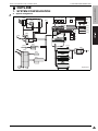
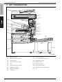
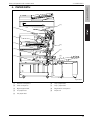
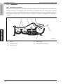
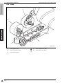
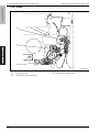
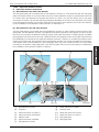
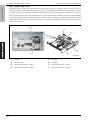
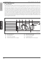
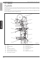
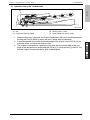
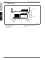
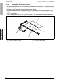
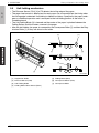
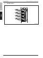
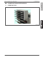
1. SYSTEM CONFIGURATION
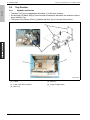
A. System configuration
[29]
[33] [34] [35]
[30]
[31]
[32]
[10]
[1]
[2]
[11]
[12]
[13]
[14]
[15]
[3]
[4]
[5]
[28]
[27]
[8]
[9]
[36]
[6]
[7]
[25]
[24]
[26]
[17]
[23]
[20]
[21]
[16]
[18]
[16]
[19]
[22]
50gat1e001ne
1
1
bizhub 501/421/361
1. SYSTEM CONFIGURATION
[1]
2
Reverse automatic document feeder
[19]
Desk (DK-506)
(DF-613) (standard equipment)
[20]
Large capacity unit (LU-203)
[2]
Main body
[21]
Dehumidifier heater *2
[3]
Image controller (IC-207)
[22]
Relay unit (RU-507)
[4]
Upgrade kit (UK-202)
[23]
Swedish punch kit G *3
[5]
Local Interface Kit (EK-703)
[24]
Finisher (FS-523)
[6]
Hard disk (HD-509)
[25]
Job separator (JS-502)
[7]
Security kit (SC-505)
[26]
Output tray kit (OT-504)
[8]
Stamp unit (SP-501)
[27]
Output tray (OT-602)
[9]
Spare TX marker stamp 2
[28]
Finisher (FS-522)
[10]
Authentication unit (Biometric type) (AU-101)
[29]
Mail bin kit (MT-502)
[11]
Authentication unit (IC card type: AU-201)
[30]
Saddle stitcher (SD-507)
[12]
Working table (WT-502)
[31]
Folding unit (included in SD-507)
[13]
Key counter kit 4 *1
[32]
Punch unit (PU-501)
[14]
Key counter *1
[33]
FAX kit (FK-502)
[15]
Key counter mount kit *1
[34]
Mount kit (MK-708)
[16]
Dehumidifier heater 1C
[35]
FAX multi line (ML-503)
[17]
Paper feed cabinet (PC-407)
[36]
i-option (LK-101/102/103) *4
[18]
Paper feed cabinet (PC-206)
*1
*2
*3
*4
1
Theory of Operation Ver.2.0 Mar. 2009
See "6.4 Option counter" in Field Service bizhub 501/421/361 main body for details.
Dehumidifier heater is set up as service part.
Swedish punch kit G is for Europe only.
Upgrade kit (UK-202) is needed for using i-option.
Theory of Operation Ver.2.0 Mar. 2009
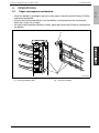
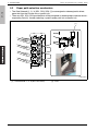
1. SYSTEM CONFIGURATION
bizhub 501/421/361
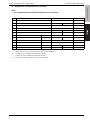
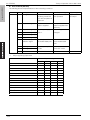
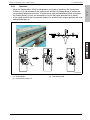
B. Configuration for optional device connection
Note
• Any combination other than those listed below is not available.
No.
Combinations for paper feeding
Combinations for finishing
1
DK-506/PC-206/PC-407 *1
OT-504
2
DK-506/PC-206/PC-407 *1
3
DK-506/PC-206/PC-407 *1
4
DK-506/PC-206/PC-407 *1
5
DK-506/PC-206/PC-407 *1
FS-522 *2*3
SD-507
6
DK-506/PC-206/PC-407 *1
FS-522 *2*3
MT-502
OT-504
Remarks
JS-502
RU-507 + FS-523
FS-522 *2*3
7
PC-206/PC-407 *4
LU-203
OT-504
8
PC-206/PC-407 *4
LU-203
9
PC-206/PC-407 *4
LU-203
10
PC-206/PC-407 *4
LU-203
11
PC-206/PC-407 *4
LU-203
FS-522 *2*3
SD-507
12
PC-206/PC-407 *4
LU-203
FS-522 *2*3
MT-502
OT-504
FS-522 *2*3
*1
Either one of DK-506, PC-206 and PC-407 can be selected.
*2
FS-522 can be installed optionally with OT-602.
*3
FS-522 can be installed optionally with PU-501.
*4
Either one of PC-206 and PC-407 can be selected.
JS-502
RU-507 + FS-523
3
2. PRODUCT SPECIFICATIONS
Theory of Operation Ver.2.0 Mar. 2009
bizhub 501/421/361
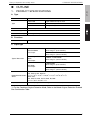
2. PRODUCT SPECIFICATIONS
A. Type
Type
Desktop type
Copying method
Indirect electrostatic method
Original stand
Fixed
Original alignment
Left rear standard
Photo conductor
OPC
Sensitizing method
Laser writing
Paper feed trays
*1
4
Two trays
500 sheet x 2, 80g/m2
Bypass feed
150 sheet x 1, 80g/m2
PC-407 *1
2,500 sheet x 1, 80g/m2
PC-206 *1
500 sheet x 2, 80g/m2
LU-203 *1
2,000 sheet x 1, 80g/m2
PC-407, PC-206, and LU-203 are optional.
2. PRODUCT SPECIFICATIONS
B. Functions
Original
Sheet, book, solid object
Max. original size
A3 or 11 x 17
Copy size
Trays 1, 2
Inch:
11 x 17, 81/2 x 14, 81/2 x 11, 81/2 x 11S, 51/2 x 81/2S,
A3, A4, A4S, Foolscap
Metric: A3, B4, A4, A4S, B5, A5S, 11 x 17, 81/2 x 11,
81/2 x 11S, Foolscap, 8K *1, 16K *1
Bypass feed
Inch:
11 x 17, 81/2 x 14, 81/2 x 11, 81/2 x 11S, 51/2 x 81/2S,
A4, Custom paper
(Max. 297.0 x 431.8mm, Min. 92.0 x 148.0 mm)
Metric: A3, B4, A4, A4S, B5, B5S *2, A5S, B6S, 11 x 17 *2,
81/2 x 11, 81/2 x 11S, Foolscap, 8K *1, 16K *1,
16KS *1, Custom paper (Max. 297.0 x 431.8mm,
Min. 92.0 x 148.0 mm)
ADU
Inch:
11 x 17, 81/2 x 14, 81/2 x 11, 81/2 x 11S, 51/2 x 81/2S,
A3, A4, A4S, Foolscap
Metric: A3, B4, A4, A4S, B5, B5S *2, A5S, 11 x 17, 81/2 x 11,
81/2 x 11S, Foolscap, 8K *1, 16K *1, 16KS *1
Magnification
Fixed magnification
Inch:
x 1.000, x 1.214, x 1.294, x 1.545, x 2.000
x 0.500, x 0.647, x 0.772, x 0.785
Metric: x 1.000, x 1.154, x 1.224, x 1.414, x 2.000
x 0.500, x 0.707, x 0.816, x 0.866
Special magnification setting
x 0.930
Preset zoom setting
3 types
Zoom magnification
x 0.25 to x 4.00 (at the step of 0.1%)
Vertical magnification
x 0.25 to x 4.00 (at the step of 0.1%)
Horizontal magnifi-
x 0.25 to x 4.00 (at the step of 0.1%)
cation
Warm-up time
60 seconds or less (bizhub 501)
30 seconds or less (bizhub 421/361)
First copy out time
3.2 seconds or less (bizhub 501)
3.6 seconds or less (bizhub 421/361)
Continuous copy speed
50 copies /min. (A4 / 81/2 x 11) (bizhub 501)
42 copies /min. (A4 / 81/2 x 11) (bizhub 421)
36 copies /min. (A4 / 81/2 x 11) (bizhub 361)
Continuous copy count
Up to 999 sheets
Original density selection
Auto density selection, Manual (9 steps), Manual underprint density (9 steps)
*1
*2
Only supported in Taiwan.
Supported in other than inch area and Taiwan.
5
bizhub 501/421/361
Theory of Operation Ver.2.0 Mar. 2009
2. PRODUCT SPECIFICATIONS
bizhub 501/421/361
Resolution
Theory of Operation Ver.2.0 Mar. 2009
Scan
600 x 600 dpi
Write
600 x 600 dpi
Image memory
205 MB
Interface section
RJ45 Ethernet, Serial port (RS232-C), Serial port (USB TypeA x 3),
Serial port (USB TypeB) *1, RJ-11 *2
*1
*2
When EK-703 is optionally installed.
1 port when MK-708 and FK-502 are optionally installed.
2 ports when MK-708, ML-503 and FK-502 x 2 are optionally installed.
C. Type of paper
High quality paper of 60 to 105 g/m2
Plain paper *1
All trays
Special paper *2
Bypass feed only
OHP film, label paper *3, blueprint master paper *3
High quality paper of 50 to 59 g/m2 (thin paper)
*1
All trays
High quality paper of 91 to 105 g/m2 (thick paper)
Bypass feed only
High quality paper of 106 to 210 g/m2 (thick paper)
Standard specified paper
Plain paper:
Inch:
Hammermill Tidal MP (20 lbs)
Metric: Konica Minolta Profi (80 g/m2)
Recycle paper:
Inch:
Hammmermill Bond (20lbs), Domtar Recycled Copy (20lbs)
Metric: Nautilus (80 g/m2)
*2
Special paper/recommended paper
Thick paper:
Inch:
Cougar Cover 65 lb
Metric: Xerox colotech 200 g/m2
Thin paper:
Inch:
Boise Cascade Bond 16 lbs
Label paper:
Inch:
AVERY 5352
OHP film:
Inch:
Metric: AVERY DPS 24
3M CG3700
Metric: Folex overhead X-500, 3M CG3700
Envelope:
Inch:
Preservation Wove (24 lbs) #6-3/4, #9, #10 (4-1/8 x 9-1/2)
Metric: Schneider Soehne Distinction 100 (100 g/m2) #lang
Schneider Soehne Briefumschlage (100 g/m2) #C5
Schneider Soehne Velin 80White (80g/m2) #C6
*3
Label paper is loaded and fed one sheet at a time.
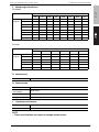
D. Maintenance
Maintenance
Every 250,000 prints (bizhub 501/421)
Every 225,000 prints (bizhub 361)
1
6
Theory of Operation Ver.2.0 Mar. 2009
2. PRODUCT SPECIFICATIONS
Power source
Inch:
bizhub 501/421/361
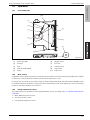
E. Machine data
AC120V 12A, 60Hz
Metric: AC220-240V 7A, 50Hz
Maximum power consumption 1,560 W or less (full system)
Dimensions
Main body
685 (W) x 823.7 (D) x 1,150 (H) mm *1
+ DF-613
+ PC or DK
Weight
*1
F.
Approx. 97 kg (with DF-613 provided)
Overturning prevention board is not included.
Operating environment
Temperature
10 to 30 °C
Humidity
10 to 80%RH (with no condensation)
Note
• The information herein may be subject to change for improvement without notice.
7
1
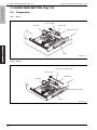
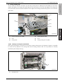
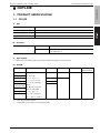
3. UNIT CONFIGURATION
Theory of Operation Ver.2.0 Mar. 2009
bizhub 501/421/361
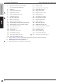
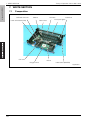
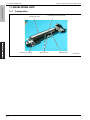
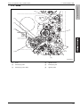
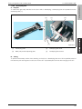
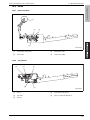
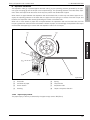
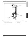
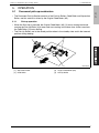
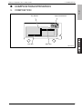
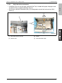
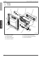
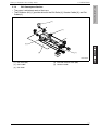
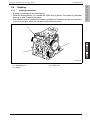
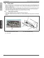
3. UNIT CONFIGURATION
[17]
[1]
[2]
[16]
[3]
[15]
[14]
[4]
[5]
[13]
[6]
[12]
[7]
[8]
[11]
[9]
[10]
50gat1c002na
8
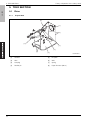
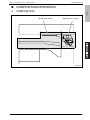
[1]
Scanner section
[10]
PC or DK (option)
[2]
Paper reverse/exit section
[11]
Paper feed section (tray 1/2)
[3]
Fusing section
[12]
Developing section
[4]
Photo conductor section
[13]
Writing section
[5]
ADU
[14]
Charging section
[6]
Transfer/separation section
[15]
Toner supply section
[7]
Registration section
[16]
Cleaning/toner recycle section
[8]
Bypass tray section
[17]
DF
[9]
LU (option)
Theory of Operation Ver.2.0 Mar. 2009
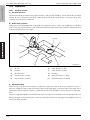
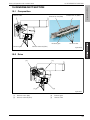
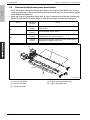
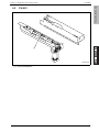
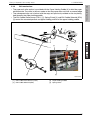
4. PAPER PATH
bizhub 501/421/361
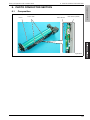
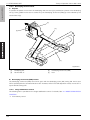
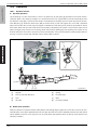
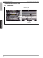
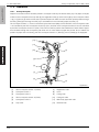
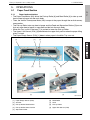
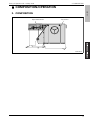
4. PAPER PATH
[1]
[9]
[8]
[7]
[2]
[6]
[3]
[4]
[5]
50gat1c003na
[1]
Reverse conveyance
[6]
Tray 2 paper feed
[2]
ADU conveyance
[7]
Tray 1 paper feed
[3]
Bypass paper feed
[8]
Registration conveyance
[4]
LU paper feed
[9]
Paper exit
[5]
PC paper feed
9
Theory of Operation Ver.2.0 Mar. 2009
bizhub 501/421/361
4. PAPER PATH
Blank page
10
Theory of Operation Ver.2.0 Mar. 2009
5. OVERALL CONFIGURATION
bizhub 501/421/361
COMPOSITION/OPERATION
5. OVERALL CONFIGURATION
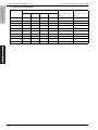
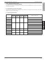
5.1
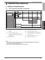
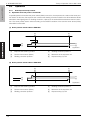
Time chart when the power is turned ON
[1] [2]
[3][4]
[5]
[6]
[7]
[8]
[9]
Item
Scanner motor
(M2)
Normal
rotation
Reverse
rotation
Exposure lamp (L1)
Fusing heater lamp /1 (L2)
Fusing heater lamp /2 (L3)
Fusing motor (M11)
Drum motor (M1)
Developing motor (M3)
Polygon motor (M5)
Laser (LDB)
Paper lift motor /1 (M7)
Upper limit sensor /1 (PS6)
Paper lift motor /2 (M8)
Upper limit sensor /2 (PS13)
50gat2e001na
[1]
Fusing heater lamps /1 (L2) and /2 (L3) turn
[5]
Drum motor (M1) turns ON
ON early
[6]
Dot diameter adjustment starts
[2]
Power switch (SW2) turns ON
[7]
The fusing temperature gets to the pre-
[3]
Initial communication between the overall
scribed temperature to start the preliminary
rotation for fusing
control board (OACB) and the printer control
[4]
board (PRCB)
[8]
Dot diameter adjustment completed
Shading correction
[9]
Warming up completed
Note
• Each operation varies according to the setting of the software DipSW in the service mode.
• The power is turned ON with DF closed.
• The power is turned ON with the lift plate of the tray down.
11
5. OVERALL CONFIGURATION
bizhub 501/421/361
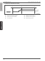
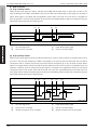
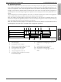
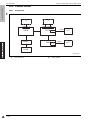
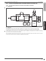
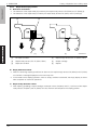
5.2
Theory of Operation Ver.2.0 Mar. 2009
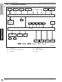
Control block diagram
CCD
IC
HDD
FK, MK
CF
USB RS232C LAN
I/F
I/F
I/F
Operation
unit
OACB
SC
Write
Section
M
FM
CL
SD
DF
PS
PRCB
SDB
M
DCPU
HV
PS
JS
[1]
1
12
[2]
[3]
[4]
LU
[5]
PC
[6]
[1]
Image bus
[4]
[2]
Clock synchronous serial bus
[5]
Other buses
Individual signal line
[3]
UART bus
[6]
SATA
FS, RU
50gat2c090nc
Theory of Operation Ver.2.0 Mar. 2009
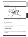
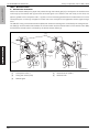
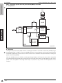
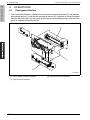
6. SCANNER SECTION
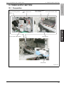
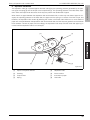
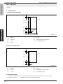
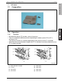
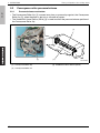
6.1
bizhub 501/421/361
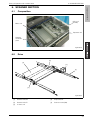
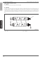
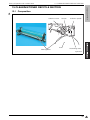
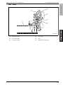
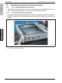
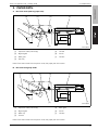
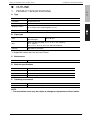
6. SCANNER SECTION
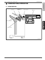
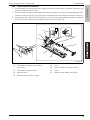
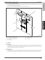
Composition
CCD unit
(CCDB)
Mirror unit
Exposure unit
Shading
correction
plate
50gat2c001na
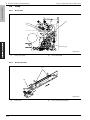
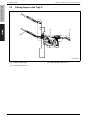
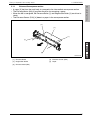
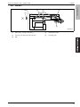
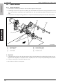
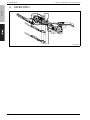
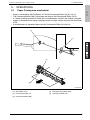
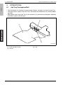
6.2
Drive
[4]
[3]
[5]
[1]
[2]
50gat2c002na
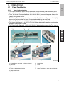
[1]
Scanner wire /Rr
[4]
Exposure unit
[2]
Scanner wire /Fr
[5]
Scanner motor (M2)
[3]
V-mirror unit
13
bizhub 501/421/361
6. SCANNER SECTION
Theory of Operation Ver.2.0 Mar. 2009
6.3
Operation
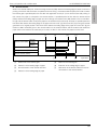
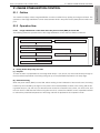
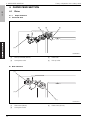
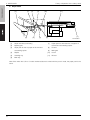
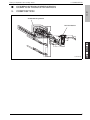
6.3.1
Scan/exposure lamp control
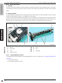
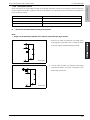
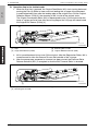
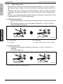
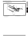
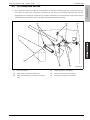
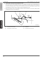
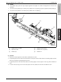
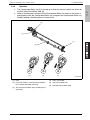
A. Operation when the power is turned ON
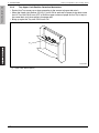
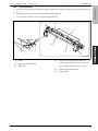
A specified period of time after the power switch (SW2) is turned on, the exposure unit conducts the home position search. At this time, the exposure unit conducts the shading correction based on the white reference board
attached to the original glass. For shading correction, 2 places on the white reference board are read for correction. The home position search varies according to the ON/OFF condition of the scanner home sensor (PS30)
when SW2 is turned ON.
(1) Home position search while in PS30 ON
[2]
[1]
[3]
[4]
[6]
[5]
50gat2c034na
[1]
Exposure unit stand-by position
[4]
[2]
Scanner home sensor (PS30)
[5]
Shading correction position 2
Movement of the exposure unit
[3]
Shading correction position 1
[6]
Exposure lamp (L1) ON
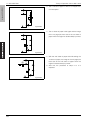
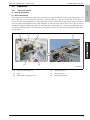
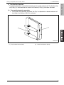
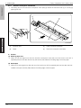
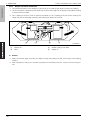
(2) Home position search while in PS30 OFF
[2]
[1]
[3]
[4]
[6]
[5]
50gat2c035na
14
[1]
Exposure unit stand-by position
[4]
[2]
Scanner home sensor (PS30)
[5]
Shading correction position 2
Movement of the exposure unit
[3]
Shading correction position 1
[6]
Exposure lamp (L1) ON
6. SCANNER SECTION
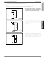
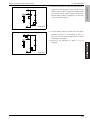
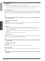
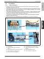
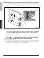
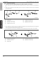
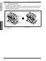
B. Operation when the start key is turned ON
For the original read mode, the following two types are available: the platen mode and the DF mode. While in the
platen mode, the exposure unit scans the original for reading. And while in the DF mode, since DF conveys the
original, the exposure unit remains at the prescribed position (DF read position) to read the original.
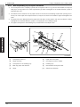
(1) When the platen is used (when DF is opened)
The operation in the platen mode varies depending on which is selected for the print density, the AE print and
the manual print.
•
When the AE print is selected
[4]
[3]
[2]
[1]
[5]
[6]
[7]
[8]
50gat2c037na
[1]
Exposure unit stand-by position
[5]
AE scan range
[2]
Position at which the image read is started
[6]
Shading correction position 1
[3]
Scanner home sensor (PS30)
[7]
Shading correction position 2
[4]
Position at which the running-up of the
[8]
Exposure lamp (L1) ON
exposure unit is started
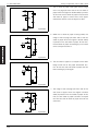
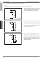
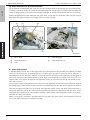
•
When the manual print is selected
[4]
[3]
[2]
[1]
[5]
[6]
[7]
50gat2c036na
[1]
Exposure unit stand-by position
[5]
Shading correction position 1
[2]
Position at which the image read is started
[6]
Shading correction position 2
[3]
Scanner home sensor (PS30)
[7]
Exposure lamp (L1) ON
[4]
Position at which the running-up of the
exposure unit is started
Note
• When the tray 1 is selected by manual, not by APS, no shading correction is made.
15
bizhub 501/421/361
Theory of Operation Ver.2.0 Mar. 2009
6. SCANNER SECTION
Theory of Operation Ver.2.0 Mar. 2009
bizhub 501/421/361
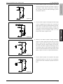
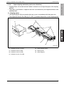
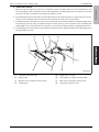
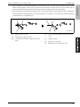
(2) When DF is used (when DF is closed)
[3]
[2]
[1]
[4]
[5]
[6]
50gat2c038na
16
[1]
Exposure unit stand-by position
[4]
Shading correction position 1
[2]
Scanner home sensor (PS30)
[5]
Shading correction position 2
[3]
DF read position
[6]
Exposure lamp (L1) ON
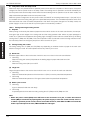
Theory of Operation Ver.2.0 Mar. 2009
Original size detection control
bizhub 501/421/361
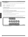
6.3.2
6. SCANNER SECTION
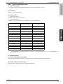
A. Detection method
The original size detection method varies for the DF mode and the platen mode.
(1) DF mode
See DF-613 Service Manual.
(2) Platen mode
•
Main scan direction
Reading is made by the CCD sensor.
•
Sub-scan direction
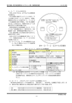
Detection is made according to the ON/OFF of the APS sensor (PS32).
Original size
*1
CCD sensor
PS32
(Detection length: mm)
(ON/OFF)
A3
297
ON
11 x 17
279.4
ON
B4
257
ON
81/2 x 14 *1
215.9
ON
81/2 x 11S
215.9
ON
A4S
210
ON
A4
297
OFF
81/2 x 11
279.4
OFF
B5
257
OFF
OFF
A5
210
B5S
182
OFF
A5
148
OFF
51/2 x 81/2
139.7
OFF
B6
128
OFF
No discrimination is made between 81/2 x 14 and 81/2 x 11S. When the size is 81/2 x 14, this is detected as
81/2 x 11S.
B. Detection timing
(1) Platen mode (while in DF closed)
When the APS timing sensor (PS31) turns on while in DF closed, the original size is detected.
(2) Platen mode (while in DF open)
When the start key is pressed, the original size is detected.
17
6. SCANNER SECTION
bizhub 501/421/361
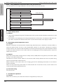
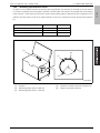
6.3.3
Theory of Operation Ver.2.0 Mar. 2009
AE control
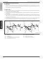
When AE is selected, the density level of the original is detected to adjust it to an appropriate density automatically. The sampling range of the original density in the AE control varies for the platen mode and the DF mode.
(1) AE sampling range in the platen mode
[5]
[1]
[7]
[6]
[5]
[2]
[2]
[4]
[3]
50gat2c039na
[1]
Original
[5]
[2]
L/100 mm
[6]
10 mm
Leading edge of the original
[3]
L mm
[7]
AE sampling range
[4]
30 mm
(2) AE sampling range in the DF mode
[4]
[1]
[6]
[5]
[4]
[3]
[2]
50gat2c040na
18
[1]
Original
[4]
20 mm
[2]
2.9 mm
[5]
Leading edge of the original
[3]
1.5 mm
[6]
AE sampling range
Theory of Operation Ver.2.0 Mar. 2009
Image processing
bizhub 501/421/361
6.3.4
6. SCANNER SECTION
The following items are provided for the image processing. For details, See "22. IMAGE PROCESSING".
•
AOC (Auto offset control)
•
AGC (Auto gain control)
•
Shading correction
•
AE processing
•
Range discrimination
•
Brightness/density conversion
•
Filter/magnification
•
Density gamma (conversion)
•
Halftone processing (error diffusion)
•
Compression
•
Storage of image data
19
7. WRITE SECTION
Theory of Operation Ver.2.0 Mar. 2009
bizhub 501/421/361
7. WRITE SECTION
7.1
Composition
Collimator lens unit
CY2 lens
Cleaner
Laser drive board (LDB)
Index mirror
CY1 lens
Index lens
Dust-proof glass
fθ lens
Polygon mirror
Index board (INDEXB)
50gat2c003na
20
7.2
Operation
7.2.1
Laser beam path
7. WRITE SECTION
bizhub 501/421/361
Theory of Operation Ver.2.0 Mar. 2009
[10]
[9]
[8]
[1]
[7]
[6]
[2]
[5]
[3]
[4]
50gat2c041na
[1]
Dust-proof glass
[6]
Polygon mirror
[2]
CY2 lens
[7]
CY1 lens
[3]
Drum
[8]
Collimator lens
[4]
Index board (INDEXB)
[9]
Laser diode
[5]
fθ lens
[10]
Index mirror
7.2.2
Write control
Image data that has been processed is converted into laser beam on the laser drive board (LDB) to be irradiated
on the drum. 1 laser diode emits 2 beams and 2 lines are written per 1 scan.
To prevent the mis-centering of a written image, an INDEX signal detected by the index board (INDEXB) is used
to decide the reference position for writing in the drum shaft direction (main scan direction) to control the starting
position of the laser irradiation onto the drum.
7.2.3
Image stabilization control
The following items are provided for the image stabilization control. For details, See "21. IMAGE STABILIZATION
CONTROL".
•
MPC (Maximum power control)
•
APC (Auto power control)
•
Dot diameter adjustment control
21
7. WRITE SECTION
bizhub 501/421/361
7.2.4
Theory of Operation Ver.2.0 Mar. 2009
Image processing
The following items are provided for the image processing. For details, See "22.2 Image processing in the write
section".
22
•
Rotation/elongation
•
PWM
•
Frequency conversion
Theory of Operation Ver.2.0 Mar. 2009
8. PHOTO CONDUCTOR SECTION
8.1
bizhub 501/421/361
8. PHOTO CONDUCTOR SECTION
Composition
Drum
Drum claw
PGC sensor
IDC sensor (IDCS)
50gat2c004na
23
bizhub 501/421/361
8. PHOTO CONDUCTOR SECTION
8.2
Drive
8.2.1
Drum drive
Theory of Operation Ver.2.0 Mar. 2009
[1]
[2]
50gat2c005na
[1]
8.2.2
Drum motor (M1)
[2]
Drum drive shaft
Drum claw drive
[1]
[2]
50gat2c006na
[1]
24
Drum claw
[2]
Drum claw solenoid (SD2)
8.3
Operation
8.3.1
Image creation control
8. PHOTO CONDUCTOR SECTION
When the print start signal turns ON [1], various motors turn ON to place each unit in the operating condition. At
the same time, the erase lamp (EL) turns ON to neutralize the drum and the charging corona charges the drum.
A specified period of time after the print start signal turns ON, the developing bias turns ON [2] and then a high
voltage is impressed [3] on the guide plate. When the preparation for image creation is made, an image is created on the drum surface by laser irradiation and developing.
A specified period of time after the registration clutch (CL1) turns ON [4], a high voltage is impressed on the
transfer corona [5] and the separation corona [6] to turn ON the transfer exposure lamp (TSL) [8] and the drum
claw solenoid (SD2) [9] sequentially. The ON timing [7] of TSL varies according to the type of paper. And the ON
time period of TSL also varies according to the setting environment. An image created on the drum is transferred
onto paper and then the paper is separated from the drum.
A specified period of time after the registration sensor (PS1) detects the trailing edge of paper and turns OFF
[10], each operation turns OFF. However, some operations turn OFF a specified period of time after PS1 detects
the trailing edge of the last paper and turns OFF [11], or a specified period of time after the fusing exit sensor
(PS3) detects the trailing edge of the last paper and turns OFF [13]. For the charging corona, the developing bias
and the guide plate bias, with the OFF timing [12] by the last paper of the transfer corona used as a starting
point, each of the OFF timing is interlocked.
[1][2] [3]
[4][5] [6] [10]
[11]
Drum motor (M1)
Developing motor (M3)
Registration sensor (PS1)
Registration clutch (CL1)
Erase lamp (EL)
Charging corona (HV)
Developing bias (HV)
Transfer corona (HV)
Separation corona (HV)
Guide plate bias (HV)
Transfer exposure lamp (TSL)
Drum claw solenoid (SD2)
Fusing exit sensor (PS3)
[7] [8] [9]
[1]
Print start signal ON
[2]
Developing bias high voltage impressed
[12]
[8]
[13]
50gat2c103na
Transfer exposure lamp (TSL) ON (This varies according to the setting environment.)
[3]
Guide plate bias high voltage impressed
[9]
Drum claw solenoid (SD2) ON
[4]
Registration clutch (CL1) ON
[10]
Trailing edge of the 1st paper detected
[5]
Transfer corona high voltage impressed
[11]
Trailing edge of the last paper detected
[6]
Separation corona high voltage impressed
[12]
Transfer of the last paper OFF
[7]
Varies according to the type of paper.
[13]
Trailing edge of the last paper detected
25
bizhub 501/421/361
Theory of Operation Ver.2.0 Mar. 2009
8. PHOTO CONDUCTOR SECTION
bizhub 501/421/361
8.3.2
Theory of Operation Ver.2.0 Mar. 2009
Drum claw control
A. Purpose
Two drum claws are employed to prevent paper from winding up around the drum (winding-up jam). The contact
and severance of the drum claws to and from the drum are made by the ON/OFF of the drum claw solenoid
(SD2).
B. Swing operation
To prevent paper from getting stained at specific points and the drum [3] from being damaged, the drum claw [2]
makes a swing operation of about 7 mm against the drum surface.
The drum claw unit [4] is provided with a projection [7]. This projection is pressed by the cam [6] provided on the
gear [5] to push out the drum claw unit backward. When the gear rotates to release the cam, the drum claw unit
is sent back to the original position by the spring [1]. This operation is repeated to swing the drum claw.
[5]
[6]
[7]
[1]
[4]
[3]
[1]
Spring
[5]
Gear
[2]
Drum claw
[6]
Cam
[3]
Drum
[7]
Projection
[4]
Drum claw unit
8.3.3
[2]
50gat2c042na
Image stabilization control
The following items are provided for the image stabilization control. For details, See "21. IMAGE STABILIZATION
CONTROL".
1
26
•
Drum rotation control
•
Dot diameter adjustment control
Theory of Operation Ver.2.0 Mar. 2009
9. CHARGING SECTION
9.1
bizhub 501/421/361
9. CHARGING SECTION
Composition
Erase lamp (EL)
Charging wire
Charging control plate
50gat2c007na
9.2
Operation
9.2.1
Charging control
A. Charging wire
The high voltage unit (HV) pressurizes 24V DC to impress a minus (–) DC voltage on the charging wire for discharge.
Charging output range: –500 to –1100 μA
B. Charging grid
To obtain a uniform charging wire discharge, a minus (–) high voltage is impressed from the high voltage unit (HV)
to the charging grid.
Charging grid voltage output range: –450 to –1090 V
9.2.2
Erase lamp (EL) control
A. Purpose
To neutralize a residual potential on the drum surface and to obtain a uniform potential on the drum surface, the
erase lamp (EL) is irradiated on the drum before charging.
B. Execution timing
The erase lamp (EL) turns ON in synch with the print start signal turning ON. And it turns OFF a specified period
of time after the fusing exit sensor (PS3) detects the trailing edge of the last paper.
27
10. TRANSFER/SEPARATION SECTION
Theory of Operation Ver.2.0 Mar. 2009
bizhub 501/421/361
10. TRANSFER/SEPARATION SECTION
10.1 Composition
Plunging prevention plate
Transfer wire
Separation wire
Transfer exposure lamp (TSL)
50gat2c008na
28
10. TRANSFER/SEPARATION SECTION
10.2 Operation
10.2.1
Transfer guide control
A. Purpose
To prevent the transfer guide plate from getting stained, a minus (–) DC voltage is impressed from the high voltage unit (HV).
Voltage impressed: –500 V
B. Execution timing
The impression of a voltage onto the transfer guide plate is made ON a specified period of time after the developing bias turns ON. And it turns OFF a specified period of time after the developing bias turns OFF.
10.2.2
Transfer/separation control
A. Transfer
The high voltage unit (HV) pressurizes a 24V DC to impress a plus (+) DC voltage on the transfer wire for discharging.
Transfer DC output range: 0 to –450 μA
B. Separation
For separation, an AC high voltage and a minus (–) DC voltage are employed. The high voltage unit (HV)
impresses a voltage onto the separation wire for discharging.
Separation AC output range: 300 to 1000 μA
Separation DC output range: 0 to –200 μA
10.2.3
Transfer exposure lamp (TSL) control
A. Purpose
The transfer exposure lamp (TSL) is turned ON to secure transferability and prevent a reverse charge to the
drum.
B. Execution timing
The transfer exposure lamp (TSL) turns ON a specified period of time after the registration clutch (CL1) turns ON.
And it turns OFF a specified period of time after the registration sensor (PS1) turns OFF.
29
bizhub 501/421/361
Theory of Operation Ver.2.0 Mar. 2009
11. DEVELOPING UNIT
Theory of Operation Ver.2.0 Mar. 2009
bizhub 501/421/361
11. DEVELOPING UNIT
11.1 Composition
Developing roller
TCR sensor (TCRS)
Developer restriction blade
Agitator screw
Agitator plate
50gat2c009na
30
Theory of Operation Ver.2.0 Mar. 2009
11. DEVELOPING UNIT
bizhub 501/421/361
11.2 Drive
[6]
[5]
[4]
[1]
[3]
[2]
50gat2c010na
[1]
Drum
[4]
Agitator screw
[2]
Developing roller
[5]
Developing unit
[3]
Developing motor (M3)
[6]
Agitator plate
31
11. DEVELOPING UNIT
Theory of Operation Ver.2.0 Mar. 2009
bizhub 501/421/361
11.3 Operation
11.3.1
Developer conveyance
Developer in the developing unit is supplied by the agitator plate [4] to the developing roller [2]. The thickness of
developer attaching to the developing roller is restricted by the developer restriction blade [5]. After completion
of transfer to the drum [1], developer remaining on the developing roller is sent back to the agitator screws [3].
The 2 agitator screws rotate in the same direction to obtain an improved conveyability when developer is
changed.
[3]
[4]
[5]
[1]
[2]
32
[1]
Drum
[4]
Agitator plate
[2]
Developing roller
[5]
Developer restriction blade
[3]
Agitator screw
50gat2c043nb
11.3.2
11. DEVELOPING UNIT
Developing bias
A. Purpose
To make toner get easily attached to the drum while in developing, a developing bias is impressed onto the
developing roller [1].
[2]
[3]
[1]
[4]
50gat2c044na
[1]
Developing roller
[3]
Developing bias shaft
[2]
Main pole position adjusting plate
[4]
Developing bias contact
B. Timing
To prevent unnecessary carriers from attaching to the drum, a developing bias turns ON a specified period of
time after the print start signal turns ON, and it turns OFF a specified period of time after charging turns OFF.
33
bizhub 501/421/361
Theory of Operation Ver.2.0 Mar. 2009
11. DEVELOPING UNIT
bizhub 501/421/361
11.3.3
Theory of Operation Ver.2.0 Mar. 2009
Developing suction control
A. Purpose
To prevent the splash of toner from the developing roller, the duct [4] is provided at 2 places of the developing
unit [1]. Toner guided into the duct is sucked in by the developing suction fan (FM6) [3] to be collected by the
suction filter /A [2].
[3]
[4]
[2]
[1]
50gat2c045na
[1]
Developing unit
[3]
Developing suction fan (FM6)
[2]
Suction filter /A
[4]
Duct
B. Developing suction fan (FM6) control
The developing suction fan (FM6) turns ON in synch with the developing motor (M3) turning ON. And it turns
OFF a specified period of time after M3 turns OFF. However, while in the TCR adjustment mode, it turns OFF in
synch with M3 turning OFF.
11.3.4
Image stabilization control
The following item is provided for the image stabilization control. For details, See "21. IMAGE STABILIZATION
CONTROL".
•
34
Toner density control
Theory of Operation Ver.2.0 Mar. 2009
12. TONER SUPPLY SECTION
bizhub 501/421/361
12. TONER SUPPLY SECTION
12.1 Composition
Toner remaining sensor
(PZS)
Toner bottle motor (M10)
Toner supply motor
(M4)
Toner bottle position
sensor (PS28)
Toner bottle sensor (PS4)
Toner hopper
Toner bottle
50gat2c011na
35
12. TONER SUPPLY SECTION
Theory of Operation Ver.2.0 Mar. 2009
bizhub 501/421/361
12.2 Drive
[5]
[4]
[1]
[2]
[3]
50gat2e003na
1
36
[1]
Toner agitator plate
[4]
Toner supply motor (M4)
[2]
Toner conveyance screw
[5]
Toner bottle motor (M10)
[3]
Toner solenoid (SD5)
12. TONER SUPPLY SECTION
12.3 Operation
12.3.1
Toner level detection control
A. Toner level detection control
Toner remaining in the toner hopper is detected by the toner remaining sensor (PZS). When toner remaining in
the hopper is found below the prescribed amount, a toner supply signal is issued to the printer control board
(PRCB). This signal is transmitted to the operation section through the overall control board (OACB). Accord-
bizhub 501/421/361
Theory of Operation Ver.2.0 Mar. 2009
ingly, OB displays a message in LCD on the LCD board (LCDB).
B. Detection timing
•
At all times while in printing.
12.3.2
Toner supply control to the toner hopper
A. Operation
When the toner remaining sensor (PZS) detects the reduced level of remaining toner, the toner bottle motor
(M10) turns ON and rotates the toner bottle to supply toner in the toner bottle to the toner hopper.
When PZS detects the toner level being restored to its prescribed level, M10 turns OFF to get back to the standby condition.
B. Toner bottle position detection
The toner supply section is provided with the toner bottle position sensor (PS28) to detect the rotational position
of the toner bottle whether it is at the home position.
12.3.3
Toner supply control to the developing unit
A. When the power switch (SW2) is turned ON
A specified period of time after SW2 turns ON, the TCR sensor (TCRS) detects the toner density in the developing unit. At this time, when a detected value is found below the initial density recorded in the CPU in the overall
control board (OACB), the toner supply motor (M4) and the toner solenoid (SD5) turn ON to supply toner from
the toner hopper to the developing unit.
B. While in printing
While in printing, the toner density is detected by the TCR sensor (TCRS). The ON time periods of the toner supply motor (M4) and the toner solenoid (SD5) are decided according to the output voltage of TCRS to supply
toner from the toner hopper to the developing unit.
TCRS output voltage
Toner supply time period
Less than 2.01 V
0 second
2.01 to 2.14 V
0.10 seconds
2.14 to 2.22 V
0.15 seconds
2.22 to 2.28 V
0.20 seconds
2.28 to 2.32 V
0.25 seconds
2.32 to 2.39 V
0.40 seconds
2.39 V or more
0.50 seconds
37
1
12. TONER SUPPLY SECTION
bizhub 501/421/361
12.3.4
Theory of Operation Ver.2.0 Mar. 2009
Toner conveyance control
A. Purpose
To convey toner in the toner bottle to the toner hopper.
B. Operation
The exit [1] of the toner bottle is normally closed. However, by setting the bottle to the toner supply section, the
accordion section is pushed and compressed to let the exit open. A bottle set to the toner supply section
rotates when the toner bottle motor (M10) turns ON. When the toner bottle rotates, toner is conveyed to the exit
of the bottle along the spiral groove engraved on the surface of the toner bottle and flows out into the toner hopper.
[1]
D
A
B
C
[2]
D
B
C
A
50gat2e002na
[1]
38
Exit
[2]
Rotation
13. CLEANING/TONER RECYCLE SECTION
13. CLEANING/TONER RECYCLE SECTION
13.1 Composition
Collection screw
Cleaning blade
Scraper
Drum
Collection paddle
bizhub 501/421/361
Theory of Operation Ver.2.0 Mar. 2009
Neutralizing sheet
50gat2c013nb
39
1
13. CLEANING/TONER RECYCLE SECTION
Theory of Operation Ver.2.0 Mar. 2009
bizhub 501/421/361
13.2 Drive
[1]
[2]
[3]
50gat2c014na
40
[1]
Drum motor (M1)
[2]
Cleaning/recycle section drive
[3]
Developer agitation drive
13. CLEANING/TONER RECYCLE SECTION
13.3 Operation
13.3.1
Cleaning operation
Toner scraped by the cleaning blade [4] is neutralized by the neutralizing sheet [2], then collected by the collection paddle [1], and finally guided to the collection screw [5]. At this time, toner remaining on the collection paddle is scraped by the scraper [6].
[5]
[6]
[1]
[4]
[3]
[2]
50gat2c047na
[1]
Collection paddle
[4]
Cleaning blade
[2]
Neutralizing sheet
[5]
Collection screw
[3]
Drum
[6]
Scraper
13.3.2
Toner collection mechanism
A. Purpose
To reuse toner scraped by the cleaning blade, the toner collection mechanism is provided.
B. Execution timing
The collection paddle to be used to collect toner is driven by the drum motor (M1) and the toner collection operation is made in synch with the ON/OFF of M1.
13.3.3
Toner conveyance operation
A. Toner conveyance mechanism
Toner collected is conveyed to the hopper in the toner supply section by the collection screw of the cleaning
section.
B. Execution timing
The collection screw is driven by the drum motor (M1) and the toner conveyance operation is made in synch
with the ON/OFF of M1.
41
bizhub 501/421/361
Theory of Operation Ver.2.0 Mar. 2009
14. PAPER FEED SECTION (Tray 1/2)
Theory of Operation Ver.2.0 Mar. 2009
bizhub 501/421/361
14. PAPER FEED SECTION (Tray 1/2)
14.1 Composition
14.1.1
Tray 1
Pick-up roller
Feed roller
Lift plate
Separation roller
Tray 1
50gat2c015na
14.1.2
Tray 2
Vertical conveyance roller
Pick-up roller
Feed roller
Lift plate
Separation roller
Tray 2
50gat2c104na
42
Theory of Operation Ver.2.0 Mar. 2009
14. PAPER FEED SECTION (Tray 1/2)
14.2.1
bizhub 501/421/361
14.2 Drive
Paper feed drive
[1]
[12]
[13]
[2]
[3]
[4]
[5]
[6]
[11]
[7]
[10]
[8]
[9]
50gat2c016na
[1]
Feed motor (M9)
[8]
Feed roller /2
[2]
Feed clutch /1 (CL4)
[9]
Separation roller /2
[3]
Feed roller /1
[10]
Pick-up roller /2
[4]
Separation roller /1
[11]
Tray 2
[5]
Vertical conveyance roller
[12]
Tray 1
[6]
Vertical conveyance clutch (CL3)
[13]
Pick-up roller /1
[7]
Feed clutch /2 (CL5)
14.2.2
Tray lift drive
[3][4]
[1]
[2]
[1]
Lift arm
[3]
Paper lift motor /1 (M7)
[2]
Lift plate
[4]
Paper lift motor /2 (M8)
50gat2c017na
43
14. PAPER FEED SECTION (Tray 1/2)
Theory of Operation Ver.2.0 Mar. 2009
bizhub 501/421/361
14.3 Operation
14.3.1
Up/down control
A. Up drive operation
The lift drive shaft [3] is rotated by the paper lift motors /1 (M7) [6] and /2 (M8) [7]. The lift drive shaft is provided
with the lift arm [1] and the lift plate [2] is pushed up when the lift drive shaft rotates. In this way, the up drive
operation of the lift plate is conducted.
B. Down drive operation
Pulling out the tray disengages the coupling [8] of the paper lift motors /1 (M7) and /2 (M8) from the lift drive
shaft. In this way, the driving force of M7 or M8 that holds the lift plate at the upper position is released and the
lift plate goes down by its own weight.
[6] [7]
[8]
[9][10]
[1]
[4] [5]
[3]
[2]
[1]
Lift arm
[6]
[2]
Lift plate
[7]
Paper lift motor /2 (M8)
[3]
Lift drive shaft
[8]
Coupling
[4]
Tray set sensor /1 (PS8)
[9]
Upper limit sensor /1 (PS6)
[5]
Tray set sensor /2 (PS14)
[10]
Upper limit sensor /2 (PS13)
50gat2c051na
Paper lift motor /1 (M7)
C. Operation timing
When the tray is set, the tray set sensors /1 (PS8) and /2 (PS14) turn ON. In this way, the paper lift motors /1
(M7) and /2 (M8) turn ON to raise the lift plate. When the lift plate goes up and the upper most paper that is
loaded turns ON the upper limit sensors /1 (PS6) and /2 (PS13), M7 and M8 turn OFF to stop the up drive operation.
When the paper feed operation causes PS6 and PS13 to turn OFF from ON while in the print operation, M7 and
M8 turn ON again to raise the lift plate. In this way, when PS6 and PS13 turn ON again, M7 and M8 turn OFF to
stop the up drive operation.
44
14.3.2
14. PAPER FEED SECTION (Tray 1/2)
Paper size detection control
A. Paper size detection mechanism
(1) Size detection in the main scan direction
The side guide plate [12] is provided with the size detection actuator [7]. And interlocked with the side guide
plate, this actuator sticks out to the rear side of the tray. The size detection actuator is provided with the 2 lines
of notches, which are detected by the paper size sensors /Fr1 (PS11) [11] and /Rr1 (PS10) [10], or the paper
size sensors /Fr2 (PS17) [3] and /Rr2 (PS16) [4] equipped individually on the rear of the main body. The notches
of the size detection actuator vary for each paper size and the paper size is detected in the main scan direction
by the combination of the ON/OFF of PS10 and PS11, or PS16 and 17.
(2) Size detection in the sub scan direction
The rear guide plate [13] is provided with the size detection actuator [1], which rotates in interlock with the rear
guide plate. The size detection actuator is provided with a projection [2]. When this projection comes at the rear
side of the tray, it pushes the detection levers [9] and [6] of the paper size boards /1 (PSB/1) [8] and /2 (PSB/2)
[6] equipped on the back of the main body. 4 detection levers are equipped on each of the paper size board and
they individually turn ON and OFF the paper size detection switches /1 (SW101) to /4 (SW104) provided on each
board. On the other hand, the projections of the size detection actuator vary in their circumference and the intervals between each of these projections, and accordingly, either one of the 4 detection levers is to be pushed
according to the position of the guide plate. In this way, the paper size in the sub scan direction is detected by
the combination of the ON/OFF of SW101 to SW104.
[12]
[13]
[8] [9]
[7]
[6][5]
[1]
[10]
[4]
[11]
[3]
[2]
[1]
Size detection actuator
[8]
Paper size board /1 (PSB/1)
[2]
Projection
[9]
Detection lever
Paper size sensor /Rr1 (PS10)
[3]
Paper size sensor /Fr2 (PS17)
[10]
[4]
Paper size sensor /Rr2 (PS16)
[11]
Paper size sensor /Fr1 (PS11)
[5]
Detection lever
[12]
Side guide plate
[6]
Paper size board /2 (PSB/2)
[13]
Rear guide plate
[7]
Size detection actuator
50gat2c048na
45
bizhub 501/421/361
Theory of Operation Ver.2.0 Mar. 2009
14. PAPER FEED SECTION (Tray 1/2)
Theory of Operation Ver.2.0 Mar. 2009
bizhub 501/421/361
B. Paper size detection table
Paper size
Paper size boards /1 (PSB/1), /2 (PSB/2)
SW101
46
SW102
SW103
SW104
Paper size sensor
Paper size sensor
/Rr1 (PS10), /Rr2
/Fr1 (PS11), /Fr2
(PS16)
(PS17)
B5
ON
ON
OFF
OFF
ON
OFF
A5S
ON/OFF
OFF
OFF
OFF
OFF
OFF
A4
ON/OFF
OFF
OFF
OFF
ON
OFF
81/2 x 11
OFF
OFF
OFF
OFF
OFF
OFF
81/2 x 11S
ON
OFF
OFF
ON
OFF
ON
B5S
OFF
OFF
ON
OFF
OFF
OFF
ON
A4S
OFF
ON/OFF
ON
ON
OFF
81/2 x 14
ON
ON
ON
OFF
ON
ON
B4
ON
ON
ON
OFF
ON
OFF
A3
ON
ON/OFF
ON
ON
ON
OFF
14.3.3
14. PAPER FEED SECTION (Tray 1/2)
Paper feed control
A. Pick-up mechanism
The pick-up roller [4] is brought up and down mechanically by the lever [6] provided on the rear side of the paper
feed unit. When the tray is set, the lever is pushed by the tray to bring down the pick-up roller. In this way, the
pick-up roller comes in contact with paper to pick it up.
[6]
[1]
[5]
[3]
[4]
[2]
50gat2c098na
[1]
Feed roller
[4]
[2]
Separation roller
[5]
[3]
When the tray is set (with the pick-up roller
brought down)
Pick-up roller
When the tray is not set (with the pick-up
roller brought up)
[6]
Lever
47
bizhub 501/421/361
Theory of Operation Ver.2.0 Mar. 2009
14. PAPER FEED SECTION (Tray 1/2)
Theory of Operation Ver.2.0 Mar. 2009
bizhub 501/421/361
B. Pick-up control
(1) Tray 1 pick-up control
When the print start signal turn ON [1], the feed motor (M9) and the feed clutch /1 (CL4) also turn ON. In this
way, the driving force of M9 is transmitted to the pick-up roller and the feed roller to pick up [2] the 1st sheet of
paper. When paper is conveyed and the registration sensor (PS1) turns ON, CL4 turns OFF to complete the
pick-up operation. The pick-up [4] operation of the 2nd and succeeding sheets of paper is conducted using the
paper feed request signal [3] as a starting point.
[1] [2]
[3]
[4]
Feed motor (M9)
Registration sensor (PS1)
Feed clutch /1 (CL4)
50gat2c099na
[1]
Print start signal ON
[3]
Paper feed request signal
[2]
Pick-up of the 1st paper
[4]
Pick-up of the 2nd paper
(2) Tray 2 pick-up control
When the print start signal turns ON [1], M9, the feed clutch /2 (CL5), and the vertical conveyance clutch (CL3)
turn ON. In this way, the driving force of M9 is transmitted to the pick-up roller, the feed roller and the vertical
conveyance roller to conduct the pick-up [2] and the vertical conveyance [3] of the 1st sheet of paper. When
paper is conveyed and the vertical conveyance sensor (PS2) turns ON, CL5 turns OFF to complete the pick-up
operation. However, since CL3 keeps turning ON, paper is conveyed to the registration section by the vertical
conveyance roller. In this manner, when PS1 turns ON, CL3 turns OFF a specified period of time after that. The
pick-up [5] and the vertical conveyance [6] of the 2nd and succeeding sheets of paper are conducted using the
paper feed request signal [4] as a starting point.
[1] [2]
[3]
[4]
[5]
[6]
Feed motor (M9)
Registration sensor (PS1)
Vertical conveyance sensor (PS2)
Feed clutch /2 (CL5)
Vertical conveyance clutch (CL3)
50gat2c100na
48
[1]
Print start signal ON
[4]
Paper feed request signal
[2]
Pick-up of the 1st paper
[5]
Pick-up of the 2nd paper
[3]
Vertical conveyance of the 1st paper
[6]
Vertical conveyance of the 2nd paper
14. PAPER FEED SECTION (Tray 1/2)
C. Separation mechanism
The separation roller [5] is pressed against the feed roller [8] by the operating pressure generated by the pressure [2] of the spring [4] and the torque of the torque limiter [3]. This operating pressure of the feed roller, separation roller and torque limiter becomes a limit torque to prevent the double feed of paper.
When there is no paper between the separation roller and the feed roller, or when only one sheet of paper is conveyed, the operating pressure of the feed roller, the paper and the spring is in excess of the limit torque, and
therefore, the separation roller rotates [6] following the rotation of the feed roller. When two or more sheets of
paper are conveyed between the separation roller and the feed roller, the limit torque is greater than the frictional
force between 2 sheets of paper, and accordingly, the separation roller stops and the lower side paper [7] in
contact with the separation roller is not conveyed.
[8]
[1]
[2]
[3]
[7]
[6]
[5]
[4]
50gat2c101na
[1]
Paper conveyance direction
[5]
Separation roller
[2]
Pressing
[6]
Driven rotation
[3]
Torque limiter
[7]
2nd sheet of paper
[4]
Spring
[8]
Feed roller
49
bizhub 501/421/361
Theory of Operation Ver.2.0 Mar. 2009
14. PAPER FEED SECTION (Tray 1/2)
bizhub 501/421/361
14.3.4
Theory of Operation Ver.2.0 Mar. 2009
Paper empty control
The paper empty of the tray is detected by the paper empty sensors /1 (PS5) [3] and /2 (PS12) [4]. And to
prompt the supply of paper before paper in the tray runs out completely, the paper near-empty sensors /1 (PS9)
[7] and /2 (PS15) [8] are equipped. The lift drive shaft [2] that brings up the lift plate [5] is provided with the actuator [1] and PS9 and PS15 are turned ON and OFF by this actuator. When a sufficient amount of paper is loaded
on the tray, the actuator turns ON PS9 and PS15. However, when the amount of paper gets reduced and the lift
plate goes up, the actuator turns OFF PS9 and PS15. In this way, it is detected that the paper loaded in the tray
comes near to an end.
[7] [8]
[1]
[2]
[3][4]
[6]
[5]
50gat2c050na
50
[1]
Actuator
[5]
Lift plate
[2]
Lift drive shaft
[6]
Coupling
[3]
Paper empty sensor /1 (PS5)
[7]
Near-empty sensor /1 (PS9)
[4]
Paper empty sensor /2 (PS12)
[8]
Near-empty sensor /2 (PS15)
14.3.5
14. PAPER FEED SECTION (Tray 1/2)
Paper remaining detection mechanism
The front cover [4] of the tray is provided with the paper remaining display window [3], and the paper remaining
in the tray can be checked through this window. The inside of the paper remaining display window is provided
with the display lever [2] which is interlocked with the up/down position of the lift plate [1]. The display lever is red
in color and it is indicated that the more the red portion that can be seen through the paper remaining display
window, the less paper there remains in the tray.
[1]
[4]
[3]
[2]
[1]
Lift plate
[3]
Paper remaining display window
[2]
Display lever
[4]
Front cover
50gat2c053nb
51
bizhub 501/421/361
Theory of Operation Ver.2.0 Mar. 2009
15. BYPASS SECTION
Theory of Operation Ver.2.0 Mar. 2009
bizhub 501/421/361
15. BYPASS SECTION
15.1 Composition
Pick-up solenoid /BP (SD1)
Feed roller
Separation roller
Lift plate
50gat2c019na
52
Theory of Operation Ver.2.0 Mar. 2009
15. BYPASS SECTION
15.2.1
bizhub 501/421/361
15.2 Drive
Paper feed drive
[4]
[1]
[2]
[3]
50gat2c018na
[1]
Feed clutch /BP (CL6)
[3]
Separation roller
[2]
Feed roller
[4]
Feed motor (M9)
15.2.2
Tray lift drive
[4]
[5]
[3]
[1]
[2]
50gat2c020na
[1]
Cam
[4]
Feed clutch /BP (CL6)
[2]
Lift plate
[5]
Pick-up solenoid /BP (SD1)
[3]
Spring
53
15. BYPASS SECTION
Theory of Operation Ver.2.0 Mar. 2009
bizhub 501/421/361
15.3 Operation
15.3.1
Up/down control
A. Up drive operation
The lift plate [4] is of the construction in which it is pushed up by the spring [5] provided on the lower section.
However, while in the stand-by condition, it is hold down by the cam [3] provided on the lift drive shaft [6]. And
the ON/OFF of the gear [7] of the lift drive shaft is controlled by the stopper [1] that is driven by the pick-up solenoid /BP (SD1) [2]. When the feed motor (M9) is turned ON by a print start signal, SD1 turns ON a specified
period of time after that. In this way, the stopper is released and the driving force of M9 is transmitted to the lift
drive shaft. When the cam that holds down the lift plate is released by the rotation of the lift drive shaft, the lift
plate is brought up by the force of the spring. When the lift sensor (PS23) [8] is turned ON by the rotation of the
lift drive shaft, SD1 turns OFF to stop the up drive of the lift plate. This up drive operation causes paper loaded in
the tray to come in contact with the feed roller to allow paper to be fed.
[7]
[2]
[8]
[6]
[1]
[6]
[5]
[4] [3]
50gat2c054na
[1]
Stopper
[5]
[2]
Pick-up solenoid /BP (SD1)
[6]
Spring
Lift drive shaft
[3]
Cam
[7]
Gear
[4]
Lift plate
[8]
Lift sensor (PS23)
B. Down drive operation
When the vertical conveyance sensor (PS2) detects the leading edge of paper and turns ON, the pick-up solenoid /BP (SD1) turns ON a specified period of time after that and turns OFF a specified period of time after the lift
sensor (PS23) turns OFF. In this way, the cam of the lift drive shaft presses down the lift tray to be placed in the
stand-by condition.
54
15.3.2
15. BYPASS SECTION
Paper size detection control
A. Size detection in the main scan direction
According to the position of the guide plate connected to the paper size VR/BP (VR1), the paper size is detected
in the main scan direction.
B. Size detection in the sub scan direction
The paper size is detected by the combination of the ON/OFF of the paper size sensors /BP1 (PS19), /BP2
(PS20), /BP3 (PS21) and /BP4 (PS22).
C. Paper size detection table
Paper size
A6S
Paper size sensors
Paper size VR/BP (VR1)
BP1
BP2
BP3
BP4
(PS19)
(PS20)
(PS21)
(PS22)
OFF
OFF
OFF
OFF
B6S
detection width (mm)
80 or more - less than 115
115 or more - 144 or less
A5
196 or more - 225 or less
B5
242 or more - 268 or less
A5S
ON
OFF
OFF
OFF
133 or more - 164 or less
B5S
169 or more - less than 196
A4S
196 or more - 225 or less
81/2 x 11
225 or more - less than 288
A4
288 or more - 330 or less
Foolscap
ON
ON
OFF
OFF
81/2 x 14
ON
ON
ON
OFF
B4
11 x 17
A3
188 or more - 235 or less
201 or more - 231 or less
242 or more - less than 268
ON
ON
ON
ON
255 or more - less than 288
288 or more - less than 301
55
bizhub 501/421/361
Theory of Operation Ver.2.0 Mar. 2009
15. BYPASS SECTION
bizhub 501/421/361
15.3.3
Theory of Operation Ver.2.0 Mar. 2009
Paper feed control
A. Pick-up control
When the feed motor (M9) is turned ON by the print start signal [1], the pick-up solenoid /BP (SD1) and the vertical conveyance clutch (CL3) also turn ON a specified period of time after that. When SD1 turns ON, the lift
plate goes up [2] and paper comes into contact with the feed roller. After that, the feed clutch /BP (CL6) turns
ON. Through these operations, the driving force of M9 is transmitted to the feed roller and the vertical conveyance roller to conduct the pick-up [3] and the vertical conveyance [4] of the 1st sheet of paper. When paper is
conveyed and the vertical conveyance sensor (PS2) turns ON, CL6 turns OFF to complete the pick-up operation. However, since CL3 keeps turning ON, paper is conveyed to the registration section by the vertical conveyance roller. In this way, when the registration sensor (PS1) turns ON, CL3 turns OFF a specified period of time
after that. The pick-up [6] and the vertical conveyance [8] of the 2nd and succeeding sheets of paper are conducted using the paper feed request signal [5] as a starting point. When the last paper turns ON PS2, SD1 turns
ON to bring down [7] the lift plate.
[1]
[3]
[4]
[5]
[6]
[8]
Feed motor (M9)
Registration sensor (PS1)
Vertical conveyance sensor (PS2)
Pick-up solenoid /BP (SD1)
Feed clutch /BP (CL6)
Vertical conveyance clutch (CL3)
[2]
56
[7]
50gat2c102na
[1]
Print start signal ON
[5]
[2]
Lift plate goes up
[6]
Paper feed request signal
Pick-up of the 2nd paper
[3]
Pick-up of the 1st paper
[7]
Lift plate goes down
[4]
Vertical conveyance of the 1st paper
[8]
Vertical conveyance of the 2nd paper
15. BYPASS SECTION
B. Separation mechanism
The separation roller [7] is pressed against the feed roller [1] by the operating pressure generated by the pressure [4] of the spring [5] and the torque of the torque limiter [6]. This operating pressure of the feed roller, separation roller and torque limiter becomes a limit torque to prevent the double feed of paper.
When there is no paper between the separation roller and the feed roller, or when only one sheet of paper is conveyed, the operating pressure of the feed roller, the paper and the spring is in excess of the limit torque, and
therefore, the separation roller rotates [3] following the rotation of the feed roller.
When two or more sheets of paper are conveyed between the separation roller and the feed roller, the limit
torque is greater than the frictional force between 2 sheets of paper, and accordingly, the separation roller stops
and the lower side paper [2] in contact with the separation roller is not conveyed.
[1]
[8]
[7]
[6]
[5]
[4]
[3]
[2]
50gat2c106na
[1]
Feed roller
[5]
[2]
2nd sheet of paper
[6]
Torque limiter
[3]
Driven rotation
[7]
Separation roller
[4]
Pressing
[8]
Paper conveyance direction
15.3.4
Spring
Paper empty control
The paper empty of the tray is detected by the paper empty sensor /BP (PS18).
57
bizhub 501/421/361
Theory of Operation Ver.2.0 Mar. 2009
16. REGISTRATION SECTION
Theory of Operation Ver.2.0 Mar. 2009
bizhub 501/421/361
16. REGISTRATION SECTION
16.1 Composition
Registration roller
Loop roller
58
50gat2c021na
Theory of Operation Ver.2.0 Mar. 2009
16. REGISTRATION SECTION
bizhub 501/421/361
16.2 Drive
[1]
[6]
[2]
[3]
[5]
[4]
50gat2c022na
[1]
Registration roller
[4]
Loop roller
[2]
Feed motor (M9)
[5]
Tray 1
[3]
Loop clutch (CL2)
[6]
Registration clutch (CL1)
59
16. REGISTRATION SECTION
Theory of Operation Ver.2.0 Mar. 2009
bizhub 501/421/361
16.3 Operation
16.3.1
Loop control
A. Registration path
Paper fed from the tray 1 [10], the tray 2 [8], the by-pass tray [6], PC/LU [7] and ADU [4] hits against the registration roller [2] through the loop roller [12]. And until the loop roller turns OFF, a loop is formed [3] and a paper
skew is corrected.
The loop roller is driven by the feed motor (M9) and the loop of paper is controlled by the registration sensor
(PS1) [13] equipped just before the registration roller.
[1]
[13]
[2]
[12]
[3]
[11]
[4]
[10]
[5]
[9]
[6]
[7]
[8]
50gat2c055na
60
[1]
Drum
[8]
Tray 2 paper conveyance
[2]
Registration roller
[9]
Paper feed unit /2
[3]
Loop
[10]
Tray 1 paper conveyance
[4]
ADU paper conveyance
[11]
Paper feed unit /1
[5]
Vertical conveyance section
[12]
Loop roller
[6]
By-pass tray paper conveyance
[13]
Registration sensor (PS1)
[7]
PC/LU paper conveyance
16. REGISTRATION SECTION
B. Registration operation
The feed motor (M9) and the loop clutch (CL2) are turned ON by the print start signal [1]. In this way, the driving
force of M9 is transmitted to the loop roller and paper conveyed from each of the paper feed sections is conveyed to the registration roller. When the registration sensor (PS1) detects the leading edge of paper and turns
ON [3], CL2 turns OFF a specified period of time after that. At this time, since paper is being conveyed for a
specified period of time after being hit against the registration roller, a loop [4] is formed and a paper skew is corrected.
The print signal [5] turns ON the registration clutch (CL1) to transmit the driving force of M9 to the registration
roller. At this time, CL2 also turns ON to drive the loop roller for a loop assist [7].
When PS1 detects the trailing edge of paper and turns OFF [8], CL1 also turns OFF a specified period of time
after that to complete the registration operation. However, CL2 keeps tuning ON to conduct a loop formation [9]
of the next paper. After that, the same operations are repeated.
When PS1 detects the trailing edge of the last paper and turns OFF [11], M9, CL1 and CL2 also turn OFF a
specified period of time after that to complete a series of registration operations.
[1]
[2] [3] [5]
[7] [8]
[10]
[11]
Feed motor (M9)
Registration sensor (PS1)
Loop clutch (CL2)
Registration clutch (CL1)
[4]
[6]
[9]
[8]
50gat2c056na
[1]
Print start signal
[2]
Conveyance of the 1st paper
Detection of the trailing edge of the 1st
[3]
Detection of the leading edge of 1st paper
[9]
[4]
Loop formation of the 1st paper
[10]
Print signal for the 2nd paper
[5]
Print signal for the 1st paper
[11]
Detection of the trailing edge of the last
[6]
1st paper registration roller ON
[7]
Loop assist of the 1st paper, and convey-
paper
Loop formation of the 2nd paper
paper
ance of 2nd of paper
61
bizhub 501/421/361
Theory of Operation Ver.2.0 Mar. 2009
17. ADU SECTION
Theory of Operation Ver.2.0 Mar. 2009
bizhub 501/421/361
17. ADU SECTION
17.1 Composition
Conveyance roller /1
Conveyance roller /2
50gat2c023na
62
Theory of Operation Ver.2.0 Mar. 2009
17. ADU SECTION
bizhub 501/421/361
17.2 Drive
[1] [2]
[3] [4]
[6]
[5]
50gat2c024na
[1]
ADU conveyance clutch /Up (CL7)
[4]
[2]
Conveyance roller /1
[5]
Conveyance roller /2
Conveyance roller /3
[3]
ADU conveyance clutch /Lw (CL8)
[6]
Feed motor (M9)
63
17. ADU SECTION
Theory of Operation Ver.2.0 Mar. 2009
bizhub 501/421/361
17.3 Operation
17.3.1
Conveyance path
Paper the one side of which has been printed is conveyed to ADU by the reverse roller [12]. The paper conveyed
to ADU is also conveyed to the loop roller [6], the registration roller [7] and the drum [8] by the conveyance rollers
/1 [2], /2 [3] and /3 [5] and the other side is printed. Paper both sides of which has been printed passes through
the fusing roller [9] and fusing exit roller [10] to be exited from the main body paper exit roller [11].
The conveyance rollers /1, /2 and /3 are driven by the feed motor (M9), but the ON/OFF of the conveyance roller
/1 is controlled by the ADU conveyance clutch /Up (CL7) and that of the conveyance rollers /2 and /3 controlled
by the ADU conveyance clutch /Lw (CL8). This control is used to prevent the interference of each sheet of paper
that circulates through the conveyance path when two or more sheets of paper are printed. And, to detect the
position of paper that is circulating, the ADU conveyance sensor /1 (PS24) [1] and /2 (PS25) [4] are equipped.
[12]
[1]
[11]
[2]
[10]
[9]
[3]
[8]
[7]
[4]
[6]
[5]
50gat2c057na
64
[1]
ADU conveyance sensor /1 (PS24)
[7]
[2]
Conveyance roller /1
[8]
Registration roller
Drum
[3]
Conveyance roller /2
[9]
Fusing roller
[4]
ADU conveyance sensor /2 (PS25)
[10]
Fusing exit roller
[5]
Conveyance roller /3
[11]
Main body paper exit roller
[6]
Loop roller
[12]
Reverse roller
17.3.2
17. ADU SECTION
Conveyance control
When printing two or more sheets of paper in the double sided print mode, the conveyance control in ADU varies according to the length of paper in the sub scan direction. The following 3 control methods are provided for
the conveyance control.
Conveyance control
Length of applicable paper in the sub scan direction
1 sheet self-contained double sided print
B4 (364 mm) to Ledger (431.8 mm)
2 sheets self-contained double sided print
Letter (215.9 mm) to B4 (364 mm)
3 sheets self-contained double sided print
B5 (182 mm) to Letter (215.9 mm)
A. 1 sheet self-contained double sided print operation
Note
• A figure in the illustration (shown in the square) represents the page number.
1. With the 1st sheet of paper fed, the image of the
2nd page (the back side of the 1st sheet of paper
when the original is double sided) is printed.
2
50gat2c058na
2. The 1st sheet of paper is conveyed to the paper
reverse/exit section, and then conveyed to ADU
2
after being turned over.
50gat2c059na
65
bizhub 501/421/361
Theory of Operation Ver.2.0 Mar. 2009
17. ADU SECTION
Theory of Operation Ver.2.0 Mar. 2009
bizhub 501/421/361
3. The 1st sheet of paper in ADU is conveyed without interruption.
2
50gat2c060na
4. The 1st sheet of paper is fed again and the image
of the 1st page (the front side of the 1st sheet of
paper when the original is double sided) is printed.
1
2
50gat2c061na
5. With the 2nd sheet of paper fed while exiting the
1st sheet of paper, the image of the 4th page (the
back side of the 2nd sheet of paper when the
2
original is double sided) is printed.
1
6. After this, the procedure of steps 2 to 5 is
repeated.
4
50gat2c062na
66
17. ADU SECTION
B. 2 sheets self-contained double sided print operation
Note
• A figure in the illustration (shown in the square) represents the page number.
1. With the 1st sheet of paper fed, the image of the
2nd page (the back side of the 1st sheet of paper
when the original is double sided) is printed.
2
50gat2c063na
2. The 1st sheet of paper is conveyed to the paper
reverse/exit section and then conveyed to ADU
2
after being turned over. At this time, the 2nd sheet
of paper is fed.
50gat2c064na
3. The image of the 4th page (the back side of the
2nd sheet of paper when the original is double
sided) is printed on the 2nd sheet of paper. At this
4
time, the 1st sheet of paper is conveyed into ADU.
2
50gat2c065na
67
bizhub 501/421/361
Theory of Operation Ver.2.0 Mar. 2009
17. ADU SECTION
Theory of Operation Ver.2.0 Mar. 2009
bizhub 501/421/361
4. The 1st sheet of paper is fed again and the image
of the 1st page (the front side of the 1st sheet of
paper when the original is double sided) is printed.
4
1
At this time, the 3rd sheet of paper is fed and the
2nd sheet of paper is turned over at the paper
2
reverse/exit section to be conveyed into ADU.
50gat2c066na
5. While the 1st sheet of paper is being exited, the
image of the 6th page (the back side of the 3rd
sheet of paper when the original is double sided)
is printed on the 3rd sheet of paper. At this time,
2
the 2nd sheet of paper is standing by on this side
1
6
of the conveyance roller /3.
4
50gat2c067na
6. The 3rd sheet of paper is conveyed to ADU after
being turned over at the paper reverse/exit section. At this time, the 2nd sheet of paper that has
6
been standing by is fed again.
2
1
4
50gat2c068na
7. The image of the 3rd page (the front side of the
2nd sheet of paper when the original is double
sided) is printed on the 2nd sheet of paper. At this
6
time, the 3rd sheet of paper has been conveyed
2
1
3
into ADU and the 4th sheet of paper is fed at the
4
same time.
50gat2c069na
68
17. ADU SECTION
8. While the 2nd sheet of paper is being exited, the
image of the 8th page (the back side of the 4th
sheet of paper when the original is double sided)
is printed on the 4th sheet of paper. At this time,
4
the 3rd sheet of paper is standing by on this side
8
3
2
of the conveyance roller /3.
1
6
50gat2c070na
9. The 4th sheet of paper is turned over at the paper
reverse/exit section to be conveyed to ADU. At
8
this time, the 3rd sheet of paper that has been
standing by is fed again.
4
10. After this, the procedure of steps 7 to 9 is
3
2
repeated.
1
6
50gat2c071na
69
bizhub 501/421/361
Theory of Operation Ver.2.0 Mar. 2009
17. ADU SECTION
Theory of Operation Ver.2.0 Mar. 2009
bizhub 501/421/361
C. 3 sheets self-contained double sided print operation
Note
• A figure in the illustration (shown in the square) represents the page number.
1. The 1st sheet of paper is fed and the image of the
2nd page (the back side of the 1st sheet of paper
when the original is double sided) is printed.
2
50gat2c072na
2. The 1st sheet of paper is conveyed to the paper
reverse/exit section and then conveyed to ADU
2
after being turned over. At this time, the 2nd sheet
of paper is fed and the image of the 4th page (the
back side of the 2nd sheet of paper when the
original is double sided) is printed.
4
50gat2c073na
3. The 1st sheet of paper is standing by at the conveyance roller /3. The 2nd sheet of paper is turned
4
over at the paper reverse/exit section to be conveyed to ADU. At this time, the 3rd sheet of paper
is fed and the image of the 6th page (the back
side of the 3rd sheet of paper when the original is
6
double sided) is printed.
2
50gat2c074na
70
17. ADU SECTION
4. The 3rd sheet of paper is conveyed to the paper
reverse/exit section and the 2nd sheet of paper is
4
6
conveyed in ADU without interruption. However,
the 1st sheet of paper remains standing by at the
conveyance roller /3.
2
50gat2c075na
5. The 1st sheet of paper is fed again and the image
of the 1st page (the front side of the 1st sheet of
6
paper when the original is double sided) is printed.
At this time, the 3rd sheet of paper is turned over
to be sent to ADU and the 2nd sheet of paper is
1
standing by at the conveyance roller /3. In this
2
way, the 4th sheet of paper is fed.
4
50gat2c076na
6. While the 1st sheet of paper is being exited, the
image of the 8th page (the back side of the 4th
6
sheet of paper when the original is double sided)
is printed on the 4th sheet of paper. At this time,
2
since the 2nd sheet of paper is standing by at the
1
conveyance roller /3, the 3rd sheet of paper stops
8
when the interval between this sheet and the 2nd
sheet of paper comes to the prescribed distance.
4
50gat2c077na
7. The 4th sheet of paper is conveyed to the paper
reverse/exit section. At this time, the conveyance
8
of the 2nd and the 3rd sheets of paper resumes in
6
ADU.
2
1
4
50gat2c078na
71
bizhub 501/421/361
Theory of Operation Ver.2.0 Mar. 2009
17. ADU SECTION
Theory of Operation Ver.2.0 Mar. 2009
bizhub 501/421/361
8. The 2nd sheet of paper is fed again and the image
of the 3rd page (the front side of the 2nd sheet of
8
paper when the original is double sided) is printed.
The 4th sheet of paper is turned over to be sent to
2
1
ADU with the 3rd sheet of paper standing by at
3
the conveyance roller /3. In this way, the 5th sheet
4
of paper is fed.
6
50gat2c079na
9. While the 2nd sheet of paper is being exited, the
image of the 10th page (the back side of the 5th
8
sheet of paper when the original is double sided)
is printed on the 5th sheet of paper. At this time,
4
3
2
1
since the 3rd sheet of paper is standing by at the
conveyance roller /3, the 4th sheet of paper stops
10
when the interval between this sheet and the 3rd
sheet of paper comes to the prescribed distance.
6
10. After this, the procedure of steps 7 to 9 is
50gat2c080na
72
repeated.
Theory of Operation Ver.2.0 Mar. 2009
18. FUSING SECTION
bizhub 501/421/361
18. FUSING SECTION
18.1 Composition
Fusing web
Fusing heater
lamp /1 (L2)
Fusing heater lamp /2 (L3)
Fusing roller
Paper exit roller
Fusing pressure roller
Decurler roller
Fusing claw
50gat2c025na
18.2 Drive
[1]
[2]
50gat2c026na
[1]
Fusing unit drive
[2]
Fusing motor (M11)
73
18. FUSING SECTION
Theory of Operation Ver.2.0 Mar. 2009
bizhub 501/421/361
18.3 Operation
18.3.1
Fusing roller drive control
A. Speed switchover control
The process speed is switched over between the high speed and the low speed according to the type of paper
selected in the paper setting of the setup menu. However, the low speed is applicable in the thick paper,
envelop, OHP, and label paper mode.
Machine type
Normal
Thick paper, envelop, OHP
and label paper mode
bizhub 501
250mm/s
bizhub 421/361
210mm/s
125mm/s
B. Preliminary rotation control
While in the warm-up, the preliminary rotation is conducted for the fusing roller and the fusing pressure roller.
The time of preliminary rotation varies according to the detected temperature of the drum temperature sensor
and the thermistors /1 (TH1) and /2 (TH2). And the starting temperature of the preliminary rotation varies for
bizhub 501 and 421/361.
C. Rotation control while in the print
The fusing motor (M11) that drives the fusing roller and the fusing pressure roller is turned ON by the print start
signal. And it turns OFF a specified period of time after the fusing exit sensor (PS3) detects the trailing edge of
the last paper.
While in the print with paper stopping at the registration section, the fusing roller and the fusing pressure roller
run idle. In this way, the fusing temperature gets near to the set temperature for each type of paper selected in
the paper setting of the setup menu.
18.3.2
Web drive control
The fusing web is driven by the web solenoid (SD4).
The number of ON times is controlled by SD4 according to the web count of the fixed part counter so that the
web shift amount per print becomes constant.
74
18.3.3
18. FUSING SECTION
Fusing temperature control
The fusing roller is heated by the fusing heater lamps /1 (L2) and /2 (L3). The fusing pressure roller is heated by
the thermal conduction from the fusing roller.
The surface temperature of the fusing roller is detected by the thermistors /1 (TH1) [2] and /2 (TH2) [1]. TH1 and
TH2 monitor the surface temperature of the fusing roller at specified intervals to control the ON/OFF of L2 and
L3 through the AC drive circuit in the DC power supply (DCPS) so that a prescribed temperature can be
obtained.
[1]
[2]
50gat2c081na
[1]
Thermistor /2 (TH2)
[2]
Thermistor /1 (TH1)
A. Warm-up
Warm-up is conducted when the main power switch (SW1), the power switch (SW2) and the interlock switch
(MS) turn ON, and also when the system returns from the low power mode or the sleep mode.
While in the warm-up, the fusing heater lamps /1 (L2) and /2 (L3) turn ON. And it turns OFF at the prescribed
temperature. The temperature at which the warm-up completes varies for bizhub 501 and 421/361.
B. While in the print
The set temperature of the fusing roller varies according to the type of paper and the paper size. The ON/OFF of
the fusing heater lamps /1 (L2) and /2 (L3) are controlled so that the prescribed temperature is obtained.
When plain paper or thick paper is selected, to prevent the set temperature from going down due to the passage of paper, the set temperature is raised up to the prescribed temperature for a specified period of time from
the start of printing for each print.
When the fusing roller and the fusing pressure roller are stopped due to the completion or interruption of the
print, each roller is kept running for a specified period of time after L2 and L3 turn OFF to avoid an overshoot.
C. While in the stand-by
While in the stand-by condition, the temperature of the fusing roller is controlled in 3 steps according to the
elapsed time after the completion of warm-up or printing, whether DF is opened or closed, and whether each
key is pushed down or not.
While in the stand-by, the ON/OFF of the fusing heater lamps /1 (L2) and /2 (L3) are controlled so that the fusing
roller gets to the prescribed temperature.
Through these control operations, an overshoot is avoided and fusibility immediately after the release from the
stand-by condition is secured.
75
bizhub 501/421/361
Theory of Operation Ver.2.0 Mar. 2009
18. FUSING SECTION
Theory of Operation Ver.2.0 Mar. 2009
bizhub 501/421/361
D. Low power mode and sleep mode
When each key is not pressed within a specified period of time after the completion of the last print, the system
changes into the low power mode or the sleep mode. The starting time for operation can be set individually for
the low power mode and the sleep mode. When the same starting time for operation is set for both modes, the
sleep mode takes precedence over the low power mode.
When the system changes into the low power mode, the ON/OFF of the fusing heater lamps /1 (L2) and /2 (L3)
is controlled so that the fusing roller gets to the prescribed temperature. The controlled temperature at this time
becomes lower than other controlled temperatures. And when the system changes into the sleep mode, the
power supply to L2 and L3 is shut off to put the system in the stand-by condition.
18.3.4
Fusing roller edge cooling control
A. Purpose
When printing continuously the sheets of paper the size of which is short in the main scan direction, the temperature gets high at both edges of the fusing roller and the fusing pressure roller where no paper passages is
made. So, to prevent the temperature from getting high, the edges of each roller are cooled down by the fusing
cooling fans /Fr (FM2) and /Rr (FM8). This control operation is also conducted to avoid a fusing overshoot when
the main body makes an emergency stop due to the occurrence of a jam.
B. Fusing cooling fan control
The fusing cooling fans /Fr (FM2) and /Rr (FM8) vary depending on whether the size of paper in the main scan
direction is large or small. And their operations also vary when a jam occurs.
(1) Small size
Small size paper refers to the one the size of which is 200 mm or less in the main scan direction.
•
ON timing
When the fusing exit sensor (PS3) detects the leading edge of paper exited and turns ON.
•
OFF timing
When the fusing motor (M11) turns OFF.
(2) Large size
Large size paper refers to the one the size of which is 201 mm or more in the main scan direction.
•
ON timing
When the detected temperature of the thermistor /2 (TH2) is over the prescribed temperature.
•
OFF timing
When the detected temperature of TH2 goes down below the prescribed temperature.
(3) When a jam occurs.
•
ON timing
A jam is detected inside the main body.
•
OFF timing
A specified period of time after the fusing cooling fans /Fr (FM2) and /Rr (FM8) turn ON.
Note
• When the power switch (SW2) turns OFF due to the occurrence of a jam, or when the interlock
switch (MS) is turned OFF by opening ADU, the power supply to each fan is shut off and, even if it
is within a specified period of time, the fan turns OFF. However, when SW2 and MS are turned ON
within a specified period of time, FM2 and FM8 turn ON again.
76
18. FUSING SECTION
C. Fusing cooling path
The air inside the machine is sucked in by the fusing cooling fans /Fr (FM2) [6] and /Rr (FM8) [1] to be blown
against the edges of the fusing roller [3] through the ducts [2] and [5]. In this way, the edges of the fusing roller
are cooled down and the surface temperature of the edges of the fusing pressure roller [4] that is in contact also
goes down.
[1]
[2]
[6]
[3]
[4]
[5]
50gat2c082na
[1]
Fusing cooling fan /Rr (FM8)
[4]
Fusing pressure roller
[2]
Duct
[5]
Duct
[3]
Fusing roller
[6]
Fusing cooling fan /Fr (FM2)
18.3.5
Envelope conveyance mechanism
When printing envelopes, to prevent the occurrence of paper crease due to the thickness of paper, it is possible
to switch the nip pressure of the fusing roller and the fusing pressure roller. The nip pressure is manually
switched by the envelope lever [1].
[1]
50gat2c083na
[1]
Envelope lever
77
bizhub 501/421/361
Theory of Operation Ver.2.0 Mar. 2009
18. FUSING SECTION
bizhub 501/421/361
18.3.6
Theory of Operation Ver.2.0 Mar. 2009
Protection against abnormality
When the thermistors /1 (TH1) and /2 (TH2) detects a stipulated temperature (233°C) 5 times at the prescribed
intervals, this is deemed to be a high temperature abnormality and the fusing heater lamps /1 (L2) and /2 (L3) are
turned OFF. The thermostat (TS) also monitors an abnormal temperature rise and, when the detected temperature gets to 220 ± 10°C, the AC power lines to L2 and L3 are shut off.
For each condition in the warm-up, print, stand-by and the low power modes, the detected temperatures of
TH1 and TH2 and the number of times when L2 and L3 turned ON are calculated. And it is considered that a
low temperature abnormality occurs when certain conditions are met. When a low temperature abnormality
occurs, the power supply to L2 and L3 is cut off.
When these fusing temperature abnormalities occur, the system is placed in the SC latch condition with a message shown in the touch panel. After repairing with the cause of abnormality identified, it is necessary to release
the SC latch by the software DipSW3-1 for restoration.
RL1
CBR
DCPS
TS
NF
RL2
AC
drive
section
L2
L3
PRCB
TH1
Control
section
RL
drive
section
RL1
RL2
TH2
50gat2c084na
18.3.7
Jam detection control
Only while in the print, when the detected temperatures of the thermistors /1 (TH1) and /2 (TH2) go down in a
moment more than the prescribed temperature, this is considered as a wind-up jam and the operation of the
main body is stopped with a message shown in the touch panel.
78
Theory of Operation Ver.2.0 Mar. 2009
19. REVERSE/EXIT SECTION
bizhub 501/421/361
19. REVERSE/EXIT SECTION
19.1 Composition
Reverse roller
Exhaust fan /Rr (FM9)
Reverse gate
Reverse gate
Reverse solenoid (SD3)
Exhaust fan /Fr (FM3)
Reverse roller
50gat2c027na
19.2 Drive
[4]
[1]
[3]
[2]
50gat2c028na
[1]
Reverse motor (M6)
[3]
Reverse gate
[2]
Reverse solenoid (SD3)
[4]
Reverse roller
79
19. REVERSE/EXIT SECTION
Theory of Operation Ver.2.0 Mar. 2009
bizhub 501/421/361
19.3 Operation
19.3.1
Conveyance control
A. Reverse gate
The reverse gate is driven by the ON/OFF of the reverse solenoid (SD3). Paper conveyed from the fusing section
is switched by the reverse gate between the paper exit section and the reverse section.
B. Conveyance path
(1) Paper exit path
The reverse solenoid (SD3) is normally turned OFF and the reverse gate [1] is held in the position in which it
blocks the conveyance path to the reverse roller [4]. In this manner, paper conveyed from the fusing exit roller
(decurler roller) [2] is guided to the main body paper exit roller [3] along the internal form of the reverse gate to be
exited.
[4]
[1]
[3]
[2]
50gat2c085na
80
[1]
Reverse gate
[3]
Main body paper exit roller
[2]
Fusing exit roller (decurler roller)
[4]
Reverse roller
19. REVERSE/EXIT SECTION
(2) Reverse path
While in the double sided print, the reverse solenoid (SD3) turns ON when the print on the back side is completed, and the reverse gate [1] is switched in the direction in which the conveyance path to the reverse roller [4]
is opened. In this way, paper conveyed from the fusing exit roller (decurler roller) [2] is guided to the reverse roller
along the external form of the reverse gate.
[4]
[1]
[3]
[2]
50gat2c086na
[1]
Reverse gate
[3]
Main body paper exit roller
[2]
Fusing exit roller (decurler roller)
[4]
Reverse roller
81
bizhub 501/421/361
Theory of Operation Ver.2.0 Mar. 2009
19. REVERSE/EXIT SECTION
bizhub 501/421/361
19.3.2
Theory of Operation Ver.2.0 Mar. 2009
Reverse control
A. Switch-back mechanism
While in the double sided print, paper that passes through the reverse gate [3] is conveyed to the outside of the
main body by the reverse roller [5] and then sent back again to the inside of the main body. At this time, the
paper is guided to the conveyance roller /1 [1] side, not to the reverse gate side from the metal frame form of the
conveyance path. In this way, the paper is turned over to be conveyed to the registration section again through
ADU.
The ON/OFF timing of the reverse solenoid (SD3) that drives the reverse gate is controlled by the fusing exit sensor (PS3) [2]. And the switchover between the normal rotation and the reverse rotation of the reverse motor (M6)
that drives the reverse roller is controlled by the reverse sensor (PS27) [4].
[5]
[4]
[1]
[3]
[2]
50gat2c087na
82
[1]
Conveyance roller /1
[4]
Reverse sensor (PS27)
[2]
Fusing exit sensor (PS3)
[5]
Reverse roller
[3]
Reverse gate
19. REVERSE/EXIT SECTION
B. Reverse control
While in the double sided print, when the fusing exit sensor (PS3) detects the leading edge of paper of which the
printing of the back side has been completed and turns ON [1], the reverse solenoid (SD3) turns ON to switch
the reverse gate a specified period of time after the registration clutch (CL1) turns ON for back side printing. In
this manner, the paper is conveyed to the reverse section. A specified period of time after the reverse sensor
(PS27) detects the leading edge of paper and turns ON [2], the reverse motor (M6) rotates in the normal direction [3] and the reverse roller conveys the paper to the outside of the main body. And then, a specified period of
time after PS3 detects the trailing edge of the paper and turns OFF [4], SD3 turns OFF [5] to bring the reverse
gate back to its original position. And when PS27 detects the trailing edge of the paper and turns OFF [6], the
rotation of M6 is switched [7] from the normal rotation to the reverse rotation and the reverse roller sends the
paper back to the inside of the main body to convey it to ADU. In this manner, the paper is turned over.
[1]
Reverse motor (M6)
[3]
[5]
[7]
Normal
rotation
Reverse
rotation
Reverse solenoid (SD3)
Fusing exit sensor (PS3)
Reverse sensor (PS27)
[2]
[4]
[6]
50gat2c088na
[1]
Switchover of the reverse gate
[5]
Return to the reverse gate
[2]
Detection of the leading edge of paper
[6]
Detection of the trailing edge of paper
[3]
Normal rotation of the reverse roller ON
[7]
[4]
Detection of the trailing edge of paper
Switchover of the reverse roller from the normal rotation to the reverse rotation
83
bizhub 501/421/361
Theory of Operation Ver.2.0 Mar. 2009
20. INTERFACE SECTION
Theory of Operation Ver.2.0 Mar. 2009
bizhub 501/421/361
20. INTERFACE SECTION
20.1 Composition
Serial port (RS-232C)
CF card slot
RJ45 Ethernet connector
USB port /1 (USB TypeA)
USB port /2 (USB TypeA)
USB port /4 (USB TypeB)
Service port
USB port /3 (USB TypeA)
a0r5t2c001ca
20.2 Specifications
Item
Serial port (RS-232C)
CF card slot
Specifications
For CS Remote Care
System management for CF card
CF card stored the following programs and the datas
1. MFP controller program (Firmware)
2. The datas (Utility/Administrator
Setting Data, Destination Storage
Data, CS Remote Care Setting
Data, All History Data) that initialized in the [System 1]-[Initialization] of the service mode
3. HDD serial number
4. HDD model type
RJ45 Ethernet connector
Network connection, Internet for ISW
USB port /1 (USB TypeA)
USB ISW, For authentication device
USB port /2 (USB TypeA)
(Biometric type: AU-101 or IC card type:
AU-201)
USB port /3 (USB TypeA)
USB port /4 (USB TypeB)
Scan to USB, USB for print
For the local connection when
installed EK-703 (Option)
Service port
For the production adjustment
This is not used in the field
84
21. IMAGE STABILIZATION CONTROL
21. IMAGE STABILIZATION CONTROL
21.1 Outline
This machine employs various image stabilization controls to realize the top quality print image at all times. The
operation of the image stabilization control varies between while in the power switch (SW2) ON and while in the
print.
21.2 Operation flow
21.2.1
Image stabilization control flow when the power switch (SW2) is turned ON
The following shows the operation flow of the image stabilization control when the SW2 is turned ON.
Power ON
E. Environmental decision control
A. Fusing heater lamp early turn-ON
B. Drum rotation
D. Fusing preliminary rotation
C. Dot diameter adjustment control
Stand-by
A. Fusing heater lamp early turn-ON
(1) Purpose
To meet the warm-up specifications, the fusing heater lamps /1 (L2) and /2 (L3) are turned ON early enough so
that the surface temperature of the fusing roller goes up to the prescribed temperature in its early stage.
(2) Execution timing
When the power switch (SW2) is turned ON, without waiting for the initialization of the overall control, the fusing
heater lamp is turned ON by the signal on the printer control board (PRCB). However, since turning ON the fusing heater lamps /1 (L2) and /2 (L3) at the same time causes an excessive inrush current, turn ON L3 first, and
then turn ON L2 a little after that. After turning ON L2 and L3, conduct the ON/OFF control at specified intervals
to maintain the prescribed temperature of the fusing roller that is stipulated in each operation mode.
85
bizhub 501/421/361
Theory of Operation Ver.2.0 Mar. 2009
21. IMAGE STABILIZATION CONTROL
Theory of Operation Ver.2.0 Mar. 2009
bizhub 501/421/361
B. Drum rotation
(1) Purpose
•
Prevent the drum charge leak such as an image flow at high humidity
•
When left in the low/normal humidity condition, prevent the uneven density due to the difference in sensitivity between the section facing the cleaner and the developing of the drum and other sections.
(2) Execution timing
It turns ON a specified period of time after the power switch (SW2) turns ON, and turns OFF when the dot diameter adjustment is completed. However, when the 30 seconds extension of the early morning drum rotation is
selected in the software DipSW setting, it turns OFF 30 seconds after the completion of the dot diameter adjustment.
Note
• For bizhub 421/361, since the early morning dot diameter adjustment is not selected by default, no
drum rotation is made.
C. Dot diameter adjustment control
(1) Purpose
Stabilize the image over a long period of time by preventing the change of the laser 1 dot diameter due to the
write system being stained or the change of developability.
(2) Method
•
Create a dot pattern patch of a fixed density on the drum. The laser PWM at this time is maximum.
•
Read this dot pattern patch with the IDC sensor (IDCS) and calculate the difference between the sensor
output and the specified value.
•
Determine the correction amount of the laser power based on a value calculated to make corrections of the
laser power.
•
Repeat several times the control operations described above.
(3) Execution timing
When left for more than 8 hours, executed a specified period of time after the power switch (SW2) is turned ON.
However, this can be changed with the software DipSW setting.
Note
• For bizhub 421/361, since the early morning dot diameter adjustment is not selected by default, no
execution is made.
D. Fusing preliminary rotation
(1) Purpose
Make uniform the surface temperature of the fusing roller and the fusing pressure roller.
(2) Execution timing
When the detected temperature of the thermistors /1 (TH1) and /2 (TH2) gets to the stipulated temperature.
Note
• The stipulated temperature at which the fusing preliminary rotation is made varies for bizhub 501
and 421/361.
86
21. IMAGE STABILIZATION CONTROL
E. Environmental decision control
(1) Purpose
To detect the environmental temperature and humidity to maintain the image quality, feedback is made to various controls.
(2) Method
A temperature sensor and a humidity sensor are equipped inside the machine.
(3) Execution timing
When the power switch (SW2) is turned ON, and only when it has been left unused for more than 8 hours after
the SW2 was turned OFF last time and the fusing temperature is considered below the stipulated temperature,
an environmental decision is made based on a value measured by the sensor.
87
bizhub 501/421/361
Theory of Operation Ver.2.0 Mar. 2009
21. IMAGE STABILIZATION CONTROL
bizhub 501/421/361
21.2.2
Theory of Operation Ver.2.0 Mar. 2009
Image stabilization control flow while in the print and the idle
The following shows the image stabilization control flow while in the print and the idle.
Print start signal ON
Every 20 prints
Start of print
A. Toner density control
C. Dot diameter adjustment control
B. Developing potential adjustment control
End of print
Stand-by
A. Toner density control
(1) Method
•
Output value obtained through the TCR adjustment which is performed after developer replacement is used
as the base.
•
Toner density in the developing unit is always detected with the TCR sensor. The detected TCR sensor output value is compared with the base value and if it is lower than the base, toner supply is started.
B. Developing potential adjustment control
(1) Purpose
Because of developer and photosensitive material being deteriorated due to durability, it becomes difficult to
secure the stable amount of toner on the photosensitive material. For that reason, calculate the correction
amount based on the machine inside temperature and the time period during which the photosensitive material
is driven and make corrections of the output values of the charging grid and the developing bias to secure the
stable amount of toner.
(2) Method
Detect the machine inside humidity with the humidity sensor (HUMS) when turning ON the power switch (SW2)
8 hours or more after turning it OFF.
Calculate the correction amount based on the machine inside humidity detected and the time period during
which the photosensitive material is driven.
Make corrections of the output value of the charging grid and the developing bias based on the correction
amount calculated.
When the time period during which SW2 is turned ON after OFF is less than 8 hours, use the value of the
machine inside humidity detected last time.
(3) Execution timing
For each job print.
C. Dot diameter adjustment
(1) Purpose
While in the continuous print, reduce the variance in image density for each print.
88
21. IMAGE STABILIZATION CONTROL
(2) Method
•
Create a dot pattern patch between images of which more than 20 prints have been run off. The laser PWM
at this time is maximum.
•
Read this dot pattern patch with the IDC sensor (IDCS) and calculate the difference between the sensor
output and the specified value.
•
Determine the correction amount of the laser power based on a value calculated to make corrections of the
laser power.
•
Repeat several times the control operations described above.
89
bizhub 501/421/361
Theory of Operation Ver.2.0 Mar. 2009
22. IMAGE PROCESSING
Theory of Operation Ver.2.0 Mar. 2009
bizhub 501/421/361
22. IMAGE PROCESSING
22.1 Image processing in the scanner section
A. Shading correction
B. AE control
C. Area discrimination
D. Brightness/density conversion
E. Filter/magnification
F. Density gamma (conversion)
G. Half tone processing (error diffusion)
H. Compression
I. Storage of image data (option)
90
22.1.1
22. IMAGE PROCESSING
Shading correction
This is the measure to obtain an even distribution from light of the CCD sensor. The following corrections are
made at the prescribed timing.
a.
White correction
The output voltage of each pixel of the CCD sensor when the white reference plate is exposed to the exposure
lamp is stored as the maximum output of the pixel.
b.
Black correction
The output voltage of each pixel of the CCD sensor when the exposure lamp is turned off is stored as the minimum output of the pixel.
Conduct calculation to find out what step in this range falls on the image data read from the original based on
the difference between the black and white data for each pixel stored in the steps a. and b. above, and output
the results of the calculation in the 10 bits accuracy.
Voltage at which the read is made
[1]
White
+1.4
0V
Width in which the read is made
[2]
Black
After shading correction
1024
White
0
Width in which the read is made
Black
50gat2c091nb
[1]
AD conversion input
[2]
Shading correction output
91
bizhub 501/421/361
Theory of Operation Ver.2.0 Mar. 2009
22. IMAGE PROCESSING
bizhub 501/421/361
22.1.2
Theory of Operation Ver.2.0 Mar. 2009
AE control
Through the AE control, a density suitable for the original density is automatically selected and the copy is made
properly.
A. Sampling area
(1) While in the platen mode
[5]
[1]
[7]
[6]
[5]
[2]
[2]
[4]
[3]
50gat2c092na
[1]
Original
[5]
[2]
L/100 mm
[6]
10 mm
Leading edge of the original
[3]
L mm
[7]
AE sampling range
[4]
30 mm
(2) While in the DF mode
[4]
[1]
[6]
[5]
[4]
[3]
[2]
50gat2c093na
[1]
Original
[4]
20 mm
[2]
2.9 mm
[5]
Leading edge of the original
[3]
1.5 mm
[6]
AE sampling range
B. Execution timing
92
•
While in the platen print: At the pre-scan before the actual scan when the print or the read starts.
•
While in the DF print
: At the same time as when the original is read.
22.1.3
22. IMAGE PROCESSING
Area discrimination
To make a copy of the original under the correct condition (to make a correct filter processing), check the read
section to see if it is a character or a dot picture, and use the results at the image processing unit at the later
stage.
22.1.4
Brightness/density conversion
The signal obtained after the shading correction is a signal corresponding to the light reflected from the original,
and this is generally called a brightness signal. In this brightness/density conversion section, the brightness signal is converted in density as shown in the graph below.
Density
255
0
Brightness
1024
50gat2c094na
93
bizhub 501/421/361
Theory of Operation Ver.2.0 Mar. 2009
22. IMAGE PROCESSING
bizhub 501/421/361
22.1.5
Theory of Operation Ver.2.0 Mar. 2009
Filter/magnification
A. Filter processing
An appropriate filter processing is made according to the type of an original and the magnification selected.
(1) Character
: Make the shading of an original conspicuous.
(2) Dot section
: Suppress moire.
(3) Picture
: Increase the reproducibility of gradation.
B. Magnification processing
For this machine, the sub scan direction magnification is made by the scan speed of the exposure unit (platen
mode) or by the conveyance speed of the DF (DF mode), and the main scan direction magnification is made by
processing images electrically.
(1) Main scan magnification processing while in enlargement
As shown in the drawing below, if the data of each pixel obtained when the original is read by the CCD are D1 to
D5, the positions of the data read when enlarged are E1 to E5. However, when the write is made only with the
data thus read, the following problems occur.
a. There occurs a clearance between data, and this results in a distorted image.
b. The data position does not fall in exactly with the write position.
As shown with dotted lines in the drawing below, when there is no read data that corresponds exactly to the
write position, a density is decided for the write as shown below and appropriate processing is made.
[1]
D1
[2]
E1
[3]
W1
D2
D3
E2
W2
W3
D4
D5
E3
W4
E4
W5
W6
E5
W7
W8
50gat2c095na
94
[1]
Position at which the original is read
[2]
Data position while in enlargement
[3]
Write position
22. IMAGE PROCESSING
(2) Main scan magnification processing while in reduction
As shown in drawing below, if the data of each pixel obtained when the original is read by the CCD are D1 to D5,
the positions of the data read when reduced are R1 to R5. They are overlapping each other and do not correspond to the write position. Therefore, a density is decided for the write as shown below and an appropriate
processing is made.
[1]
D1
[2]
R1
[3]
W1
D2
R2
W2
D3
R3
D4
R4
W3
D5
R5
W4
W5
50gat2c096na
[1]
Position at which the original is read
[2]
Data position while in reduction
[3]
Write position
(3) Density adjustment
With the density (256 gradation) shown in the axis of coordinate and the position shown in the axis of abscissas,
when E2-E1 in the drawing of "(1) Main scan magnification processing while in enlargement" is shown in 16
steps in the direction of the axis of abscissas, the following drawing is obtained. When the position to the written
data W2 is " ," the density S can be obtained in the following expression.
S = E1 + {(E2 – E1) / 16} x
255
E2
W2
Density
S
E1
0
0
Position
15
50gat2c097na
95
bizhub 501/421/361
Theory of Operation Ver.2.0 Mar. 2009
22. IMAGE PROCESSING
bizhub 501/421/361
22.1.6
Theory of Operation Ver.2.0 Mar. 2009
Scanner gamma correction
To the data obtained after the filter/magnification processing, select a density curve corresponding to the density
button selected on the operation panel. An appropriate density curve is provided for each of the character/picture/character and the picture/thin character modes.
22.1.7
Halftone processing (error diffusion)
To make effective use of the installed memory and obtain an excellent copy image, error diffusion processing is
employed, which is one of the pseudo-intermediate processing methods.
22.1.8
Compression
To store more image data, data is stored temporarily in the image memory after the images has been compressed.
22.1.9
Storage of image data
The image/setting of the originals read by the scanner or the images sent from the IC can be stored as a file in
the hard disk in the main body. (option)
96
Theory of Operation Ver.2.0 Mar. 2009
22. IMAGE PROCESSING
bizhub 501/421/361
22.2 Image processing in the write section
A. Rotation/elongation
B. Frequency conversion
C. PWM
A. Rotation/elongation
Rotate the image in the direction of 90 degrees and 180 degrees as necessary.
When outputting images from the memory, expand the compressed data to restore them to their original state.
B. Frequency conversion
Write in the memory once the data after the PWM conversion and read it in accord with the write clock signal of
the printer.
C. PWM
The period of time the laser is turned ON is changed by changing the pulse width.
97
23. OTHERS
Theory of Operation Ver.2.0 Mar. 2009
bizhub 501/421/361
23. OTHERS
23.1 Fan control
23.1.1
Composition
[9]
[10]
[11]
[8]
[7]
[1]
[6]
[2]
[5]
[3]
[4]
50gat2c029nb
98
[1]
Exhaust fan /Rr (FM9)
[7]
[2]
Exhaust fan /Fr (FM3)
[8]
Fusing cooling fan /Fr (FM2)
Fusing cooling fan /Rr (FM8)
[3]
CPU cooling fan (FM11)
[9]
Power supply cooling fan (FM1)
[4]
Conveyance suction fan (FM5)
[10]
Overall control board cooling fan (FM10)
[5]
Drum cooling fan (FM4)
[11]
Developing cooling fan (FM7)
[6]
Developing suction fan (FM6)
Theory of Operation Ver.2.0 Mar. 2009
Operation
bizhub 501/421/361
23.1.2
23. OTHERS
A. Power supply cooling fan (FM1) control
(1) Purpose
Cool down the DC power supply (DCPS) and the high voltage unit (HV2) with suction air.
(2) ON timing
•
It turns ON a specified period of time after the drum motor (M1) turns ON.
•
While in the auto toner supply mode and the TCR adjustment mode, it turns ON in synch with the turn-ON
of M1.
•
While in the low power mode and the stand-by condition, it turns ON in synch with the turn-ON of the drum
cooling fan (FM4).
(3) OFF timing
•
While in the initial charging mode, the auto toner supply mode and the TCR adjustment mode, it turns OFF
in synch with the turn-OFF of the drum motor (M1).
•
In cases other than the above, it turns OFF a specified period of time after M1 turns OFF.
•
While in the low power mode and the stand-by condition, it turns OFF in synch with the turn-OFF of FM4.
B. Fusing cooling fan /Fr (FM2) and /Rr (FM8) control
(1) Purpose
•
While in the continuous print of small size paper (paper width: 200 mm or less), cool down both edges of
the fusing roller to suppress a temperature rise on the section of the fusing roller through which no paper
passes.
•
Suppress a temperature rise when printing large size paper (paper width: 201 mm or more).
•
Suppress a fusing overshoot caused by an emergency stop when a jam occurs.
(2) ON timing
•
•
While in the print of small size paper, they turn ON when the fusing exit sensor detects the first job paper.
While in the print of large size paper, they turn ON when the thermistor /2 (TH2) goes over the prescribed
temperature.
•
They turn ON when the print operation is stopped by a jam.
(3) OFF timing
•
While in the print of small size paper, they turn OFF in synch with the turn-OFF of the fusing motor (M11).
•
While in the print of large size paper, they turn OFF when TH2 detects a temperature lower than the prescribed temperature.
•
They turn OFF a specified period of time after it turns ON by a jam.
C. Exhaust fan /Fr (FM3) and /Rr (FM9) control
(1) Purpose
With exhaust air, cool down paper conveyed and remove heat around the reverse section in the machine.
(2) ON timing
•
They turn ON in synch with the turn-ON of the drum motor (M1).
(3) OFF timing
•
While in the initial charging mode and the TCR adjustment mode, they turn OFF in synch with the turn-OFF
of M1.
•
In cases other than the above, they turn OFF a specified period of time after the turn-OFF of M1.
99
bizhub 501/421/361
23. OTHERS
Theory of Operation Ver.2.0 Mar. 2009
D. Drum cooling fan (FM4) control
(1) Purpose
Cool around the drum and the toner bottle with suction air.
(2) ON timing
•
After completion of the print, it turns ON a specified period of time after the drum motor (M1) turns OFF.
•
It turns ON when the machine inside temperature goes over the prescribed temperature.
(3) OFF timing
•
It turns OFF a specified period of time after it turns ON after completion of the print.
•
While it turns ON after completion of the print, it turns OFF the moment M1 turns ON.
•
It turns OFF when the machine inside temperature goes down below the prescribed temperature.
E. Conveyance suction fan (FM5) control
(1) Purpose
Exhaust by sucking air around the conveyance path between the drum and the fusing unit, and stabilize the
conveyability of paper and remove exhaust heat and ozone at the same time.
(2) ON timing
•
It turns ON in synch with the turn-ON of the drum motor (M1).
•
While in the low power mode and the stand-by condition, it turns ON in synch with the turn-ON of the drum
cooling fan (FM4).
(3) OFF timing
•
While in the initial charging and the TCR adjustment mode, it turns OFF in synch with the turn-OFF of M1.
•
In cases other than the above, it turns OFF a specified period of time after M1 turns OFF.
•
While in the low power mode and the stand-by condition, it turns OFF in synch with the turn-OFF of FM4.
F.
Developing suction fan (FM6) control
(1) Purpose
Suck air from the underside of the developing unit to prevent the splash of toner and exhaust air.
(2) ON timing
•
It turns ON in synch with the turn-ON of the developing motor (M3).
(3) OFF timing
100
•
It turns OFF a specified period of time after M3 turns OFF.
•
While in the TCR adjustment mode, it turns OFF in synch with the turn-OFF of M3.
Theory of Operation Ver.2.0 Mar. 2009
23. OTHERS
bizhub 501/421/361
G. Developing cooling fan (FM7)
(1) Purpose
Take in fresh air to cool down the developing motor (M3).
(2) ON timing
•
After completion of the print, it turns ON a specified period of time after M3 turns OFF.
•
While in the auto toner supply mode, it turns ON in synch with the turn-ON of M3.
•
It turns ON when the machine inside temperature goes over the prescribed temperature.
(3) OFF timing
•
After completion of the print, it turns OFF a specified period of time after it turns ON.
•
While in the auto toner supply mode, it turns OFF in synch with the turn-OFF of M3.
•
It turns OFF when the machine temperature goes down below the prescribed temperature.
H. Overall control board cooling fan (FM10) control
(1) Purpose
Cool down the overall control board (OACB) with suction air.
(2) ON timing
•
It turns ON when the power switch (SW2) turns ON.
(3) OFF timing
•
I.
It turns OFF when SW2 turns OFF.
CPU cooling fan (FM11)
(1) Purpose
Blow fresh air on the heat sink and cool down CPU.
(2) ON timing
•
It turns ON in synch with the turn-ON of the main power switch (SW1).
(3) OFF timing
•
Setting HDD, FAX and the network
•
Not Setting HDD, FAX and the network : Turns OFF only while the sleep mode.
: Does not turn OFF.
101
bizhub 501/421/361
23. OTHERS
Theory of Operation Ver.2.0 Mar. 2009
23.2 Counter control
23.2.1
Composition
[2]
CN1000
[1]
CN35
CN36
OACB
PRCB CN30
PWB1
SDB CN64
3 6
CN939
CN936
TCT
KCT
LCDB
50gat2c030nb
[1]
1
102
Coin vendor /2
[2]
Copy Vender
23.2.2
23. OTHERS
Operation
A. Paper exit counter
Item
Specifications/mechanism
Total counter (TCT)
• Display accumulated number of prints in all print modes.
Electronic counter
• Display accumulated number of prints on the touch
• Counts up by a paper exit signal.
panel.
• Data collection *1
• Counts up by a paper exit signal.
Key counter (KCT), optional
• Counting the designated number of prints allows no further copy operation (can be removed).
*1
For data collected, See "10.6 Counter" in Field service bizhub 501/421/361 Main body. (See P.199)
[2]
[1]
CN936 (KCT connecting connector)
[1]
[2]
50gat2c031nb
Total counter (TCT)
103
bizhub 501/421/361
Theory of Operation Ver.2.0 Mar. 2009
bizhub 501/421/361
23. OTHERS
Theory of Operation Ver.2.0 Mar. 2009
B. Coin vendor/2 (Parallel)
The following shows the specifications of the connecting connector.
Connector Pin No.
36
1
Signal name
M1 signal
Description
Output timing
Type of signal
Output from the start
L output while in the
Open collec-
key being turned ON
print operation
tor output
up to the completion of
paper exit
2
Paper feed signal
Output each time
L output each time
paper is supplied
paper is supplied from
each tray
3
Paper size signal (0)
Signal output by paper
When the paper size is
4
Paper size signal (1)
sizes *1
changed
5
Paper size signal (2)
6
Paper size signal (3)
7
Double sided print
Signal output while in
While in the selection
selection signal
the double sided print
of the double sided
8
CPF signal (0)
Signal output by CPF
9
CPF signal (1)
modes
of the CPF mode
10
P.GND
Ground
—
print
*1
—
Output signals by paper sizes
Size
104
While in the selection
Paper size signal
(3)
(2)
(1)
A3
L
L
H
(0)
L
B4
L
L
L
L
A4
L
H
H
L
A4S
H
L
H
L
B5
L
H
L
L
B5S
H
L
L
L
Special
L
H
L
H
11 x 17
L
L
H
H
H
81/2 x 14
L
L
L
81/2 x 11
L
H
H
H
81/2 x 11S
H
L
H
H
51/2 x 81/2 / A5
L
L
H
L
8 x 13, 81/8 x 131/4, 81/4 x 13, 81/2 x 13
H
L
L
H
Theory of Operation Ver.2.0 Mar. 2009
23. OTHERS
23.3.1
bizhub 501/421/361
23.3 Parts that operate when the power switch is turned ON
Parts that operate when the main power switch (SW1) is turned ON
A. Composition
SW2
PWB4
SW1
PWB1
DCPS
5VDC
CBR
NF
DCPS
section
IC
12VDC
OACB
FK
HD
SC
24VDC
PC
LU
PRCB
50gat2c032nb
B. Operation
Turning ON the main power switch (SW1) supplies an AC power source to DC power supply (DCPS).
In this way, each power source of 12V DC and 5V DC is supplied to the overall control board (OACB).
OACB supplies 12V DC and 5V DC to the operation board /1 (PWB1) to be placed in the condition of standing
by for the turn-ON of the power switch (SW2).
When equipped optionally with the FAX kit (FK-502) and the hard disk (HD-509), each power source of 12V DC
and 5V DC (FK-502) and 5V DC (HD509) is supplied through OACB.
105
1
bizhub 501/421/361
23. OTHERS
23.3.2
Theory of Operation Ver.2.0 Mar. 2009
Parts that operate when the power switch (SW2) is turned ON
A. Composition
SW2
PWB4
PWB1
SW1
NF
RL2
CBR
RL1
OACB
DCPS
section
24VDC
L2, L3
AC drive
section
DCPS
50gat2c033nb
B. Operation
Turning ON the power switch (SW2) transmits an ON signal of SW2 to the overall control board (OACB) through
the operation board /1 (PWB1). In this way, OACB sends out a control signal to the DC power supply (DCPS)
and DCPS supplies each power source of 12V DC and 5V DC to all boards and optional devices, including the
printer control board (PRCB).
After that, OACB sends out to DCPS a control signal that generates a 24V DC power source, which is supplied
to all drive boards and optional devices. And when the main relay (RL1) and the sub relay (RL2) turn ON, an AC
power source is supplied to the fusing heater lamps /1 (L2) and /2 (L3) to start the initial operation of this
machine.
1
106
23. OTHERS
23.4 Authentication unit
23.4.1
Authentication unit (Biometric type) (AU-101)
•
A finger vein pattern is used for personal identification.
•
Vein patterns are inside the body and cannot be visually recognized. This makes vein patterns extremely difficult to forge or falsify. The vein pattern authentication system can provide high security.
•
With ultra-red LED radiation, a finger vein pattern is captured by camera and its image is created. The vein
pattern image is registered and a person can be identified if the person's vein pattern matches the registered one at the time of user authentication.
Ultra-red LED
Finger
Vein image
Camera
Authentication unit (AU-101)
23.4.2
•
•
A00JT2C256AA
Vein
Authentication unit (IC card type: AU-201)
A non-contact IC card, such as an employee ID card, is used for personal identification.
The system supports the communications protocol in compliance with Type A, Type B, and Felica (Type C)
of ISO14443.
•
Only Felica and Type A cards can be used for bizhub 501/421/361 machines.
•
Simply placing the IC card on the authentication unit will let the unit read the data from the card.
Abcde Fgdhi
ABCDE_Co.
Non-contact IC card
Authentication unit (AU-201)
A00HT2C302AA
107
bizhub 501/421/361
Theory of Operation Ver.2.0 Mar. 2009
Theory of Operation Ver.2.0 Mar. 2009
bizhub 501/421/361
23. OTHERS
Blank page
108
SERVICE MANUAL
Theory of Operation
DF-613
2008.05
Ver. 1.0
Revision history
After publication of this service manual, the parts and mechanism may be subject to change for
improvement of their performance.
Therefore, the descriptions given in this service manual may not coincide with the actual machine.
When any change has been made to the descriptions in the service manual, a revised version will be
issued with a revision mark added as required.
Revision mark:
• To indicate clearly a section revised, 1 is shown at the left margin of the revised section.
The number inside 1 represents the number of times the revision has been made.
• To indicate clearly a page that contains the revision, 1 is shown near the page number of the
corresponding page.
The number inside 1 represents the number of times the revision has been made.
NOTE
Revision marks shown in a page are restricted only to the latest ones with the old ones deleted.
• When a page revised in Ver. 2.0 has been changed in Ver. 3.0:
The revision marks for Ver. 3.0 only are shown with those for Ver. 2.0 deleted.
• When a page revised in Ver. 2.0 has not been changed in Ver. 3.0:
The revision marks for Ver. 2.0 are left as they are.
2008/05
1.0
—
Date
Service manual Ver.
Revision mark
Issue of the first edition
Descriptions of revision
Theory of Operation Ver.1.0 May. 2008
CONTENTS
DF-613
CONTENTS
DF-613
OUTLINE
1.
PRODUCT SPECIFICATIONS ................................................................................1
2.
PAPER PATH ...........................................................................................................4
2.1
In 1-sided mode ....................................................................................................4
2.2
In 2-sided mode ....................................................................................................4
COMPOSITION/OPERATION
3.
COMPOSITION .......................................................................................................5
4.
DRIVE......................................................................................................................6
5.
OPERATION............................................................................................................7
5.1
Document pick-up mechanism..............................................................................7
5.1.1
Pick-up operation ..........................................................................................7
5.2
Document feed/conveyance mechanism ..............................................................8
5.3
Raised/lowered position detecting mechanism...................................................12
5.3.1
DF 15° open/close detection mechanism....................................................12
5.3.2
DF open/close detection mechanism ..........................................................12
i
Theory of Operation Ver.1.0 May. 2008
DF-613
CONTENTS
Blank Page
ii
Theory of Operation Ver.1.0 May. 2008
1. PRODUCT SPECIFICATIONS
OUTLINE
PRODUCT SPECIFICATIONS
DF-613
1.
A. Type
Name
Reverse Automatic Document Feeder
Paper Feed
Paper Feed from top of stack
Type
Turnover
Switch back system
Paper Exit
Straight exit system
Installation
Screw cramp to the main unit
Document Alignment
Center
Document Loading
Left image side up
B. Functions
Modes
1-Sided Mode / 2-Sided Mode
C. Paper type
Standard Mode
Plain Paper
Type of Document
Mixed Original Detection
Mode
Plain Paper
FAX Mode
Plain Paper
1-Sided Mode
35 to 128 g/m2 (9.25 to 34 lbs)
2-Sided Mode
50 to 128 g/m2 (13.25 to 34 lbs)
1-Sided / 2-Sided Mode
50 to 128 g/m2 (13.25 to 34 lbs)
1-Sided Mode
35 to 128 g/m2 (9.25 to 34 lbs)
2-Sided Mode
50 to 128 g/m2 (13.25 to 34 lbs)
Inch area
A3, A4S, A4, B4, B5S, B5
Detectable Document
11 x 17, 81/2 x 14, 81/2 x 11S, 81/2 x 11, 81/2 x 51/2S, 81/2 x 51/2
Size*1
Metric area
A3, A4S, A4, A5S, A5, B4, B5S, B5, B6S
11 x 17, 81/2 x 11S, 81/2 x 11
Capacity
80 sheets (80 g/m2 and load height of 11 mm or less)
*1: For the Combined Original Detection Mode, Refer to the Mixed Original Detection Enabled
Size Combination Table.
1
1. PRODUCT SPECIFICATIONS
Theory of Operation Ver.1.0 May. 2008
DF-613
D. Paper feed prohibited originals
• If fed, trouble occurrence will be highly possible.
Type of Original
Possible Trouble
Original that is stapled or clipped.
Feed failure, damage to the original, or drive failure
due to clip clogging
Book original
Feed failure, damage to the original, or drive failure
Original weighing less than 35g/m2 or 128g/m2
Feed failure
or more
Torn original
Feed failure, damaged sheet
Highly curled original (15 mm or more)
Original misfeed due to dog-ear or skew
OHP transparencies
Feed failure
Label Sheet
Feed failure
Offset master
Feed failure
Sheets clipped or notched
Damaged sheet
Sheets patched
Patched part folded or torn sheet
E. Paper feed not guaranteed originals
• If fed, paper feed will be possible to some extent but trouble occurrence will be possible.
Type of Original
Sheets lightly curled
(Curled amount: 10 - 15 mm)
Possible Trouble
Dog-eared, exit failure
Heat Sensitive Paper
Edge folded, exit failure, conveyance failure
Coated Paper (Ink Jet Paper)
Take-up failure, conveyance failure
Translucent paper
Take-up failure, conveyance failure
Paper immediately after paper exit from the
main unit
Take-up failure, conveyance failure
Paper with many punched holes (e.g., loose
Multi-page feed due to flashes from holes
leaf) limited to vertical feeding
2
Sheets with 2 to 4 holes
Conveyance failure
Sheets two-folded or Z-folded
(amount of non-flatness: 15 mm or less)
Take-up failure, conveyance failure, image deformation
Sheets folded
Image deformation, multi-page feed, take-up failure
Theory of Operation Ver.1.0 May. 2008
1. PRODUCT SPECIFICATIONS
DF-613
F. Mixed original feed chart
For Metric
Reference original (original with a maximum width)
Other
originals
A3
A4
B4S
B5
A4S
A5
B5S
A5
A3
U
{
—
—
—
—
—
—
A4
{
U
—
—
—
—
—
—
B4S
~
~
U
{
—
—
—
—
B5
~
~
{
U
—
—
—
—
A4S
~
~
~
~
U
{
—
—
A5
~
~
~
~
{
U
—
—
B5S
X
X
~
~
~
~
U
—
A5S
X
X
X
X
X
X
X
U
U: Same size {: Same group ~: Different group X: Mix prohibited —: No need to set
For Inch
Reference original (original with a maximum width)
11 x 17
Other
originals
81/2 x 11
81/2 x 14
81/2 x 11S
51/2 x 81/2
51/2 x 81/2 S
11 x 17
U
{
—
—
—
—
81/2 x 11
{
U
—
—
—
—
81/2 x 14
~
~
U
{
{
—
81/2 x 11S
~
~
{
U
{
—
51/2 x 81/2
~
~
{
{
U
—
51/2 x 81/2S
X
X
X
X
X
U
U: Same size {: Same group ~: Different group X: Mix prohibited —: No need to set
G. Maintenance
Maintenance
Same as the main body.
H. Machine data
Power Requirements
24V DC ± 10% (supplied from the main body)
Max. Power
Consumption
48 W or less
Dimensions
582 (W) x 558 (D) x 145 mm (H)
Weight
Approx. 10 kg
I.
Operating environment
Temperature
10 to 30°C
Humidity
10 to 80% RH (with no condensation)
NOTE
• These specifications are subject to change without notice.
3
2. PAPER PATH
2.
DF-613
2.1
Theory of Operation Ver.1.0 May. 2008
PAPER PATH
In 1-sided mode
[3]
[2]
[1]
[1] Exit
16eat1c001na
[3] Feed (Scanning the 1st side)
[2] Conveyance and turnover
2.2
In 2-sided mode
[3]
[2]
[1]
16eat1c002na
[1] Exit
[2] Conveyance and switchback
4
[3] Feed (Scanning the 1st side)
Conveyance and turnover (Scanning the 2nd
side)
Conveyance
Theory of Operation Ver.1.0 May. 2008
3. COMPOSITION
COMPOSITION/OPERATION
COMPOSITION
DF-613
3.
Document feed section
Conveyance section
Switchback section
Document exit section
16eat2c001na
5
4. DRIVE
DRIVE
DF-613
4.
Theory of Operation Ver.1.0 May. 2008
[1]
[2]
16eat2c002na
[1] Original Feed Motor (M1)
6
[2] Original Conveyance Motor (M2)
Theory of Operation Ver.1.0 May. 2008
5.1
OPERATION
Document pick-up mechanism
• The Document Pick-Up Section consists of the Pick-Up Rollers, Feed Roller and Separation
Roller, and this section is driven by the Original Feed Motor (M1).
5.1.1
Pick-up operation
• When the Start key is pressed, the Original Feed Motor (M1) [3] starts rotating backward,
causing the Pick-Up Roller [4] to lower and start rotating at the same time. At the same time,
the Feed Roller [2] starts rotating.
• The Pick-Up Rollers are in the raised position when in the standby state and in the lowered
position during feeding.
[3]
[4]
[2]
[1]
[1] Separation Roller
[3] Original Feed Motor (M1)
[2] Feed Roller
[4] Pick-Up Roller
16eat2c003na
7
DF-613
5.
5. OPERATION
5. OPERATION
5.2
Theory of Operation Ver.1.0 May. 2008
Document feed/conveyance mechanism
DF-613
• When the original reaches the Registration Sensor, the Original Feed Motor (M1) [5] starts
rotating forward and, at the same time that the Pickup Roller goes up, drive is then supplied
to the Registration Roller [3].
• When the Original Conveyance Motor (M2) [4] starts rotating forward, the two Conveyance
Rollers [2] and the Exit/Turnover Roller [1] feed the document toward the exit direction.
Parts
Direction of
Rotation
Backward
rotation
M1
Forward
rotation
M2
Details
The Pickup Rollers lower and start rotating and the Feed
Roller rotates.
The Registration Roller rotates.
Backward
rotation
The Conveyance Roller and Exit/Turnover Roller rotate in
the direction to turn over the original.
Forward
rotation
The Conveyance Roller and Exit/Turnover Roller rotate in
the direction to feed the original out.
[5]
[1]
[4]
[3]
[2]
16eat2c004na
[1] Exit/Turnover Roller
[4] Original Conveyance Motor (M2)
[2] Conveyance Roller
[5] Original Feed Motor (M1)
[3] Registration Roller
8
Theory of Operation Ver.1.0 May. 2008
5. OPERATION
A. Operation flow in the 1-sided mode
DF-613
[4]
[1]
[3]
[2]
16eat2c005na
[1] Exit
[3] Scanning the 1st side
[2] Original Exit Sensor (PS10)
[4] Original Detection Sensor (PS8)
1. When the Start key is pressed, the Original Feed Motor (M1) starts rotating backward,
causing the Pick-Up Roller to lower and start a paper take-up sequence.
2. A specified period of time after the leading edge of the original turns ON PS8 [4], the
scanning of the 1st side of the original starts.
3. The original is conveyed for a given period of time after the trailing edge of the last
page of the document has deactivated the PS10 [2]. It is then fed into [1] the Exit Tray
and the Original Conveyance Motor (M2) is deenergized.
9
DF-613
5. OPERATION
Theory of Operation Ver.1.0 May. 2008
B. Operation flow in the 2-sided mode
1. When the Start key is pressed, the Original Feed Motor (M1) starts turning backward,
causing the Pick-Up Roller to lower and start feeding the 1st page of the document.
A specified period of time after the leading edge of the original turns ON the Original
Detection Sensor (PS8) [4], the scanning of the 1st side of the original starts.
The Original Conveyance Motor (M2) is deenergized to stop [1] the original after the
lapse of a given period of time after the trailing edge of the 1st page has deactivated
the Original Exit Sensor (PS10) [2].
[4]
[1]
[3]
[2]
16eat2c006na
[1] Stop
[3] Scanning the 1st side
[2] Original Exit Sensor (PS10)
[4] Original Detection Sensor (PS8)
2. M2 is turned backward to turn over [3] the original. After the Registration Roller, M2 is
turned forward to allow the Scanner to scan the backside of the 1st page.
3. After the conveyance sequence for turnover has been started, the Pressure Roller
Release Solenoid (SD1) is energized so that the Exit/Turnover Roller is retracted.
[3]
[1]
[2]
[1] Stop
[2] Scanning the 2nd side
10
16eat2c007na
[3] Turnover
Theory of Operation Ver.1.0 May. 2008
5. OPERATION
DF-613
4. To ensure that pages of the document are in the proper order, the page is turned over
[3] again before being ejected [1] into the Exit Tray.
[3]
[1]
[2]
[1] Exit
16eat2c008na
[3] Turnover
[2] Scanning the 2nd side
11
5. OPERATION
DF-613
5.3
5.3.1
Theory of Operation Ver.1.0 May. 2008
Raised/lowered position detecting mechanism
DF 15° open/close detection mechanism
• When DF is closed down to about 15° or less, the Original Cover Angle Detection Lever of
the main body is pressed down to turn ON the APS Timing Sensor (PS31).
5.3.2
DF open/close detection mechanism
• A magnet is provided so that the open/close of DF can be detected on the main body side.
• When DF is closed, the DF Open/Close Switch (SW3) of the main body is turned ON by the
magnet.
[1]
a0ret2c001ca
[1] DF Open/Close Switch (SW3)
12
SERVICE MANUAL
Theory of Operation
PC-206
(
501/421/361 (
2008.05
Ver. 1.0
Revision history
After publication of this service manual, the parts and mechanism may be subject to change for
improvement of their performance.
Therefore, the descriptions given in this service manual may not coincide with the actual machine.
When any change has been made to the descriptions in the service manual, a revised version will be
issued with a revision mark added as required.
Revision mark:
• To indicate clearly a section revised, 1 is shown at the left margin of the revised section.
The number inside 1 represents the number of times the revision has been made.
• To indicate clearly a page that contains the revision, 1 is shown near the page number of the
corresponding page.
The number inside 1 represents the number of times the revision has been made.
NOTE
Revision marks shown in a page are restricted only to the latest ones with the old ones deleted.
• When a page revised in Ver. 2.0 has been changed in Ver. 3.0:
The revision marks for Ver. 3.0 only are shown with those for Ver. 2.0 deleted.
• When a page revised in Ver. 2.0 has not been changed in Ver. 3.0:
The revision marks for Ver. 2.0 are left as they are.
2008/05
1.0
—
Date
Service manual Ver.
Revision mark
Issue of the first edition
Descriptions of revision
Theory of Operation Ver.1.0 May. 2008
CONTENTS
PC-206
CONTENTS
PC-206
OUTLINE
1.
PRODUCT SPECIFICATIONS ................................................................................1
2.
PAPER PATH ...........................................................................................................2
COMPOSITION/OPERATION
3.
COMPOSITION .......................................................................................................3
4.
DRIVE......................................................................................................................4
5.
OPERATIONS .........................................................................................................5
5.1
Paper Feed Section ..............................................................................................5
5.1.1
Paper feed mechanism..................................................................................5
5.1.2
Paper lifting motion........................................................................................6
5.2
Tray Section ..........................................................................................................7
5.2.1
Paper size detection ......................................................................................7
5.2.2
Paper level indicator mechanism...................................................................8
i
Theory of Operation Ver.1.0 May. 2008
PC-206
CONTENTS
Blank Page
ii
Theory of Operation Ver.1.0 May. 2008
1. PRODUCT SPECIFICATIONS
OUTLINE
PRODUCT SPECIFICATIONS
PC-206
1.
A. Type
Name
2 way Paper Take-Up Cabinet
Type
Front loading type 2 way paper take-up device
Installation
Desk type
Document Alignment
Center
B. Paper type
Paper Type
Same as the main body.
Paper Size
Metric: A3, B4, A4, A4S, B5, A5S, 11 × 17, 81/2 × 11, 81/2 × 11S, Foolscap, 8K *1, 16K *1
Inch: 11 × 17, 81/2 × 14, 81/2 × 11, 81/2 × 11S, 51/2 × 81/2S, A3, A4, A4S, Foolscap
Tray 3
500 sheets (80 g/m2)
Tray 4
500 sheets (80 g/m2)
Capacity
*1: Only supported in Taiwan.
C. Maintenance
Maintenance
Same as the main body.
D. Machine specifications
Power Requirements
24V DC ± 10 %, 5V DC ± 5 % (supplied from the main body)
Power Consumption
15 W or less
Dimensions
570 mm (W) × 577 mm (D) × 300 mm (H)
Weight
Approx. 26.0 kg
E. Operating environment
Temperature
Same as the main body.
Humidity
Same as the main body.
NOTE
• The information herein may be subject to change for improvement without notice.
1
2. PAPER PATH
PAPER PATH
PC-206
2.
Theory of Operation Ver.1.0 May. 2008
[4]
[1]
[2]
[3]
4061t1c001na
2
[1] Convey to the main body
[3] Tray 4 paper feed
[2] Vertical conveyance through PC
[4] Tray 3 paper feed
Theory of Operation Ver.1.0 May. 2008
3. COMPOSITION
COMPOSITION/OPERATION
COMPOSITION
PC-206
3.
Tray 3
Paper Feed
Section
Tray 4
4061t2c001na
3
4. DRIVE
DRIVE
PC-206
4.
Theory of Operation Ver.1.0 May. 2008
[4]
[1]
[3]
[2]
4061t2c002na
4
[1] Vertical Conveyance Motor /3 (M120)
[3] Vertical Conveyance Motor /4 (M121)
[2] Paper Feed Motor /4 (M123)
[4] Paper Feed Motor /3 (M122)
Theory of Operation Ver.1.0 May. 2008
5.1
OPERATIONS
Paper Feed Section
5.1.1
PC-206
5.
5. OPERATIONS
Paper feed mechanism
• The Paper Feed Motor (M122, M123) drives the Pick-up Roller [8] and Feed Roller [6] to
take up and feed a sheet of paper into the main body.
• Then, the Vertical Conveyance Motor /3, /4 (M120, M121) transports the paper through the
vertical conveyance section.
• The Pick-up Roller takes up sheet of paper and the Feed Roller and Separation Roller [5]
ensure that only one sheet of paper is separated and fed into the main body.
• When the Tray is slid in, the lever [7] is pushed to lower the Pick-up Roller.
• The Upper Limit Sensor /3, /4 (PS114, PS123) [9] then detects the upper limit position when
the paper lifting plate is raised.
• The Paper Empty Sensor /3, /4 (PS115, PS124) [1] detects when paper in the Tray runs out.
[7]
[8]
[6]
[9]
[5]
[2]
[4]
[3]
[1]
4061t2c003na
[1] Paper Empty Sensor /3, /4 (PS115, PS124)
[6] Feed Roller
[2] Actuator
[7] Lever
[3] Pick-up Roller Feed Position
[8] Pick-up Roller
[4] Pick-up Roller Home Position
[9] Upper Limit Sensor /3, /4 (PS114, PS123)
[5] Separation Roller
5
5. OPERATIONS
5.1.2
Theory of Operation Ver.1.0 May. 2008
Paper lifting motion
PC-206
• When the Tray is slid into the main body and the Tray Set Sensor /3, /4 (PS112, PS121) is
activated, the Paper Lift Motor /3, /4 (M124, M125) starts rotating to raise the Lifting Plate
[3].
• The paper stack of the Tray pushes up the Pick-up Roller [1]. When the upper limit position
is detected by the Upper Limit Sensor /3, /4 (PS114, PS123) [4], it stops raising the lifting
plate.
• As paper is consumed during the print cycle and the Pick-up Roller is lowered, M124, M125
is energized until PS114, PS123 is blocked again.
A. When the Tray is slid in
1. The lifting plate [3] goes up and the top surface of the paper stack pushes up the roller
[1].
2. The lifting motion stops as soon as the Upper Limit Sensor /3, /4 (PS114, PS123)
detects the upper limit position.
[1]
[4]
[3]
[2]
4061t2c004na
[1] Pick-up Roller
[3] Lifting Plate
[2] Lift-up Arm
[4] Upper Limit Sensor /3, /4 (PS114, PS123)
B. During a print cycle
1. As the paper is consumed, the Upper Limit Sensor /3, /4 (PS114, PS123) [1] is
unblocked.
2. The lifting plate goes up.
[1]
4061t2c005na
[1] Upper Limit Sensor /3, /4 (PS114, PS123)
6
Theory of Operation Ver.1.0 May. 2008
5.2.1
Tray Section
Paper size detection
• Moving the Sub Scan Direction Restriction Plate of the Tray rotates the Circular Plate [1]
provided on the bottom of the Tray.
• The length of paper in the sub scan direction is detected by the Paper Size Detection Switch
[8] provided on the Paper Size Detect Boards /3 and /4 (PSDB3, PSDB49) [7] that is driven
by the Lever interlocked with the Circular Plate.
• The detection of the length of paper in the main scan direction is made by detecting a notch
on the Lever of the Main Scan Direction Restriction Plate by the Paper Size Sensors /Rr3,
/Fr3 (PS118, PS119) [2] or /Rr4, /Fr4 (PS127, PS128) [3].
• The paper size is determined by the combination of the 4 Paper Size Detection Switches
and the 2 Paper Size Sensors.
• The setting of the Tray is detected by the Tray Set Sensors /3, /4 (PS112, PS121) [6].
[9]
[7]
[5]
[8]
[1]
[6]
[4]
[3]
[2]
4061t2c006na
[1] Circular Plate
[6] Tray Set Sensor /3, /4 (PS112, PS121)
[2] Paper Size Sensor /Rr3, /Rr4 (PS118,
PS127)
[7] Paper Size Detect Board /3, /4 (PSDB3,
PSDB4)
[3] Paper Size Sensor /Fr3, /Fr4 (PS119, PS128)
[8] Paper Size Detection Switch
[4] Paper Lift Motor /3, /4 (M124, M125)
[9] Sub scan direction size detection
[5] Main scan direction size detection
7
PC-206
5.2
5. OPERATIONS
5. OPERATIONS
5.2.2
Theory of Operation Ver.1.0 May. 2008
Paper level indicator mechanism
PC-206
• All Trays are universal paper size tray.
• There is a window in the front cover of the Tray that serves as the Paper Level Indicator [3]
showing the amount of paper that is still available for use.
• A red lever [1] is attached to the bottom plate [5] of the Tray and as the lifting plate [4] raises,
the red lever becomes visible in the window.
• The more the red lever is visible, the lesser the amount of paper will be available for use.
[5]
[4]
[3]
[2]
[1] Lever
[4] Lifting Plate
[2] Operated by the Lifting Plate
[5] Tray Bottom Plate
[3] Paper Level Indicator
8
[1]
4061t2c007nb
SERVICE MANUAL
Theory of Operation
PC-407
(
501/421/361 (
2008.05
Ver. 1.0
Revision history
After publication of this service manual, the parts and mechanism may be subject to change for
improvement of their performance.
Therefore, the descriptions given in this service manual may not coincide with the actual machine.
When any change has been made to the descriptions in the service manual, a revised version will be
issued with a revision mark added as required.
Revision mark:
• To indicate clearly a section revised, 1 is shown at the left margin of the revised section.
The number inside 1 represents the number of times the revision has been made.
• To indicate clearly a page that contains the revision, 1 is shown near the page number of the
corresponding page.
The number inside 1 represents the number of times the revision has been made.
NOTE
Revision marks shown in a page are restricted only to the latest ones with the old ones deleted.
• When a page revised in Ver. 2.0 has been changed in Ver. 3.0:
The revision marks for Ver. 3.0 only are shown with those for Ver. 2.0 deleted.
• When a page revised in Ver. 2.0 has not been changed in Ver. 3.0:
The revision marks for Ver. 2.0 are left as they are.
2008/05
1.0
—
Date
Service manual Ver.
Revision mark
Issue of the first edition
Descriptions of revision
Theory of Operation Ver.1.0 May. 2008
CONTENTS
PC-407
CONTENTS
PC-407
OUTLINE
1.
PRODUCT SPECIFICATION...................................................................................1
2.
PAPER PATH ...........................................................................................................2
COMPOSITION/OPERATION
3.
COMPOSITION .......................................................................................................3
4.
DRIVE......................................................................................................................4
5.
OPERATIONS .........................................................................................................5
5.1
Paper Feed Section ..............................................................................................5
5.1.1
5.2
Paper feed mechanism..................................................................................5
Tray Section ..........................................................................................................6
5.2.1
Up/down mechanism.....................................................................................6
5.2.2
Shift Gate drive mechanism ..........................................................................7
5.2.3
Shifter drive mechanism................................................................................8
5.2.4
Paper empty detection ..................................................................................9
i
Theory of Operation Ver.1.0 May. 2008
PC-407
CONTENTS
Blank Page
ii
Theory of Operation Ver.1.0 May. 2008
1. PRODUCT SPECIFICATION
OUTLINE
PRODUCT SPECIFICATION
PC-407
1.
A. Type
Name
2500 sheets paper feed cabinet
Type
Front loading type LCC
Installation
Desk type
Document Alignment
Center
B. Paper type
Paper Type
Same as the main body.
Paper Size
Metric: A4
Inch: 81/2 × 11
Capacity
2500 sheets (80 g/m2)
C. Maintenance
Maintenance
Same as the main body.
D. Machine specifications
Power Requirements
24V DC ± 10 %, 5V DC ± 5 % (supplied from the main body)
Power Consumption
45 W or less
Dimensions
570 mm (W) × 577 mm (D) × 300 mm (H)
Weight
Approx. 26.0 kg
E. Operating environment
Temperature
Same as the main body.
Humidity
Same as the main body.
NOTE
• The information herein may be subject to change for improvement without notice.
1
2. PAPER PATH
PAPER PATH
PC-407
2.
Theory of Operation Ver.1.0 May. 2008
[1]
[2]
[5]
[4]
[3]
4061t1c201na
[1] Convey to the main body
[4] From the Sub Tray to Main Tray
[2] Tray paper feed
[5] Sub Tray
[3] Main Tray
2
Theory of Operation Ver.1.0 May. 2008
3. COMPOSITION
COMPOSITION/OPERATION
COMPOSITION
PC-407
3.
Tray Section
Sub Tray
Paper Feed Section
Main Tray
4061t2c201na
3
4. DRIVE
DRIVE
PC-407
4.
Theory of Operation Ver.1.0 May. 2008
[7]
[8]
[9]
[10]
[1]
[2]
[6]
[3]
[5]
4
[4]
[1] Paper Lift Motor (M5)
[6] Shift Gate Drive Section
[2] Paper Lift Drive Section
[7] Tray Lock Solenoid (SD1)
4061t2c202na
[3] Shifter Drive Section
[8] Paper Feed Motor (M1)
[4] Shift Motor (M4)
[9] Vertical Conveyance Motor (M2)
[5] Shift Gate Motor (M3)
[10] Vertical Conveyance Drive Section
Theory of Operation Ver.1.0 May. 2008
OPERATIONS
5.1
Paper Feed Section
5.1.1
PC-407
5.
5. OPERATIONS
Paper feed mechanism
• The Paper Feed Motor (M1) drives the Pick-up Roller [8] and Feed Roller [6] to take up and
feed a sheet of paper into the main body.
• Then, the Vertical Conveyance Motor (M2) transports the paper through the vertical conveyance section.
• The Pick-up Roller takes up sheet of paper and the Feed and Separation Rollers [5] ensure
that only one sheet of paper is separated and fed into the main body.
• When the Tray is slid in, the lever [7] is pushed to lower the Pick-up Roller.
• The Upper Limit Sensor (PS4) [9] then detects the upper limit position when the paper lifting
plate is raised.
• The Paper Empty Sensor (PS3) [1] detects when paper in the Main Tray runs out.
[7]
[8]
[6]
[9]
[5]
[2]
[1]
[4]
[3]
[1] Paper Empty Sensor (PS3)
[6] Feed Roller
[2] Actuator
[7] Lever
[3] Pick-up Roller Feed Position
[8] Pick-up Roller
[4] Pick-up Roller Home Position
[9] Upper limit Sensor (PS4)
4061t2c203na
[5] Separation Roller
5
5. OPERATIONS
5.2
PC-407
5.2.1
Theory of Operation Ver.1.0 May. 2008
Tray Section
Up/down mechanism
• The Main Tray [3] is suspended by the cables [1] at the front and rear.
• As the Paper Lift Motor (M5) [5] turns forward or backward, the cables are wound to raise or
lower the Main Tray.
• The Lower Limit Sensor (PS13) [2] detects the Main Tray at its lower limit position.
[1]
[2]
[5]
[3]
[4]
4061t2c204na
[1] Cables
[4] Sub Tray
[2] Lower Limit Sensor (PS13)
[5] Paper Lift Motor (M5)
[3] Main Tray
6
Theory of Operation Ver.1.0 May. 2008
5.2.2
5. OPERATIONS
Shift Gate drive mechanism
PC-407
• If the Main Tray runs out of paper, while the Sub Tray is loaded with paper, the paper stack
on the Sub Tray is moved to the Main Tray [2].
• At this time, the Shift Gate Motor (M3) [4] is energized to retract the front and rear Shift
Gates [1].
[1]
[4]
[3]
[2]
[1]
[1] Shift Gate move to outside
[3] Shifter
[2] Shifter move
[4] Shift Gate Motor (M3)
4061t2c205na
7
5. OPERATIONS
5.2.3
Theory of Operation Ver.1.0 May. 2008
Shifter drive mechanism
PC-407
• After completion of the evacuation of the Shift Gate, starts the movement of the Shifter [2].
• The movement of paper from the Sub Tray to the Main Tray is made by the Shifter that is
driven by the Shift Motor (M4) [1].
• The stopping of the movement of the Shifter to the Main Tray side is made by the Shift Position Sensor (PS11) [4].
• The movement to the home position starts when the Tray Release Key is pressed.
• The stopping of the movement of the Shifter to the home position is made by the Shift Home
Sensor (PS12) [3].
[3]
[2]
[2]
[4]
[1]
8
[1]
[1] Shift Motor (M4)
[3] Shift Home Sensor (PS12)
[2] Shifter
[4] Shift Position Sensor (PS11)
4061t2c206na
Theory of Operation Ver.1.0 May. 2008
5.2.4
5. OPERATIONS
Paper empty detection
[4]
PC-407
• Paper empty detection of Main Tray is performed by Main Tray Empty Board (MEB) [2].
• Paper empty detection of Sub Tray is performed by Sub Tray Empty Sensor (PS9) [3].
[1]
[3]
[2]
[1] Main Tray
[3] Sub Tray Empty Sensor (PS9)
[2] Main Tray Empty Board (MEB)
[4] Sub Tray
4061t2c207na
9
Theory of Operation Ver.1.0 May. 2008
PC-407
5. OPERATIONS
Blank Page
10
SERVICE MANUAL
Theory of Operation
LU-203
2008.05
Ver. 1.0
Revision history
After publication of this service manual, the parts and mechanism may be subject to change for improvement of their performance.
Therefore, the descriptions given in this service manual may not coincide with the actual machine.
When any change has been made to the descriptions in the service manual, a revised version will be
issued with a revision mark added as required.
Revision mark:
• To indicate clearly a section revised, 1 is shown at the left margin of the revised section.
The number inside 1 represents the number of times the revision has been made.
• To indicate clearly a page that contains the revision, 1 is shown near the page number of the
corresponding page.
The number inside 1 represents the number of times the revision has been made.
NOTE
Revision marks shown in a page are restricted only to the latest ones with the old ones deleted.
• When a page revised in Ver. 2.0 has been changed in Ver. 3.0:
The revision marks for Ver. 3.0 only are shown with those for Ver. 2.0 deleted.
• When a page revised in Ver. 2.0 has not been changed in Ver. 3.0:
The revision marks for Ver. 2.0 are left as they are.
2008/05
1.0
—
Date
Service manual Ver.
Revision mark
Issue of the first edition
Descriptions of revision
Theory of Operation Ver.1.0 May. 2008
CONTENTS
LU-203
CONTENTS
LU-203
OUTLINE
1. PRODUCT SPECIFICATION . . . . . . . . . . . . . . . . . . . . . . . . . . . . . . . . . . . . . . . . . . . . . . . . . . . . . . . . . . . . 1
2. PAPER PATH . . . . . . . . . . . . . . . . . . . . . . . . . . . . . . . . . . . . . . . . . . . . . . . . . . . . . . . . . . . . . . . . . . . . . . . 2
COMPOSITION/OPERATION
3. COMPOSITION . . . . . . . . . . . . . . . . . . . . . . . . . . . . . . . . . . . . . . . . . . . . . . . . . . . . . . . . . . . . . . . . . . . . . 3
4. PAPER FEED SECTION . . . . . . . . . . . . . . . . . . . . . . . . . . . . . . . . . . . . . . . . . . . . . . . . . . . . . . . . . . . . . . . 4
4.1
Drive . . . . . . . . . . . . . . . . . . . . . . . . . . . . . . . . . . . . . . . . . . . . . . . . . . . . . . . . . . . . . . . . . . . . . . . . . . 4
4.1.1
4.2
Paper feed drive. . . . . . . . . . . . . . . . . . . . . . . . . . . . . . . . . . . . . . . . . . . . . . . . . . . . . . . . . . . . . 4
Operation . . . . . . . . . . . . . . . . . . . . . . . . . . . . . . . . . . . . . . . . . . . . . . . . . . . . . . . . . . . . . . . . . . . . . . 5
4.2.1
Paper feed control . . . . . . . . . . . . . . . . . . . . . . . . . . . . . . . . . . . . . . . . . . . . . . . . . . . . . . . . . . . 5
4.2.2
Remaining paper detection control. . . . . . . . . . . . . . . . . . . . . . . . . . . . . . . . . . . . . . . . . . . . . . . 7
5. TRAY SECTION . . . . . . . . . . . . . . . . . . . . . . . . . . . . . . . . . . . . . . . . . . . . . . . . . . . . . . . . . . . . . . . . . . . . . 8
5.1
Drive . . . . . . . . . . . . . . . . . . . . . . . . . . . . . . . . . . . . . . . . . . . . . . . . . . . . . . . . . . . . . . . . . . . . . . . . . . 8
5.1.1
5.2
Tray lift drive. . . . . . . . . . . . . . . . . . . . . . . . . . . . . . . . . . . . . . . . . . . . . . . . . . . . . . . . . . . . . . . . 8
Operation . . . . . . . . . . . . . . . . . . . . . . . . . . . . . . . . . . . . . . . . . . . . . . . . . . . . . . . . . . . . . . . . . . . . . . 9
5.2.1
Tray lift control . . . . . . . . . . . . . . . . . . . . . . . . . . . . . . . . . . . . . . . . . . . . . . . . . . . . . . . . . . . . . . 9
i
Theory of Operation Ver.1.0 May. 2008
LU-203
CONTENTS
Blank page
ii
Theory of Operation Ver.1.0 May. 2008
1. PRODUCT SPECIFICATION
LU-203
OUTLINE
1. PRODUCT SPECIFICATION
A. Type
Type
Side mount type large volume paper feed tray
B. Functions
Maximum tray capacity
2,000 sheets (80 g/m2)
C. Type of paper
Paper type *1
Plain paper, recycled paper, high quality paper of 60 to 105 g/m2
Paper size
A4, 81/2 x 11
*1
Recommended paper
Plain paper
Inch:
Hammermill Tidal MP (20 lbs)
Metric: Konica Profi (80 g/m2), Konica Minolta Original (80 g/m2)
Recycled paper
Inch:
Weyehaeuser Recycled Laser Copy (20 lbs)
Metric: Nautilus (80 g/m2)
D. Maintenance
Maintenance
Same as the main body.
E. Machine data
Power source
24/5V DC (supplied from the main body)
Power consumption
30 W or less (internal heater is not used)
Dimensions
424 (W) x 515 (D) x 295 (H) mm
Weight
Approx. 16 kg
F.
Operating environment
Temperature
Same as the main body
Humidity
Same as the main body
Note
• The information herein may be subject to change for improvement without notice.
1
2. PAPER PATH
Theory of Operation Ver.1.0 May. 2008
LU-203
2. PAPER PATH
[3]
[4]
[5]
[1]
[2]
16aat1c001na
2
[1]
Lift plate
[4]
Feed roller
[2]
Separation roller
[5]
Pick-up roller
[3]
Conveyance roller
Theory of Operation Ver.1.0 May. 2008
3. COMPOSITION
LU-203
COMPOSITION/OPERATION
3. COMPOSITION
Paper feed section
Tray section
16aat2c001na
3
4. PAPER FEED SECTION
Theory of Operation Ver.1.0 May. 2008
4. PAPER FEED SECTION
LU-203
4.1
4.1.1
Drive
Paper feed drive
A. Front side drive
[3]
[4]
[1]
[2]
16aat2c002na
[1]
Pick-up solenoid (SD151)
[3]
Feed roller
[2]
Conveyance roller
[4]
Pick-up roller
B. Rear side drive
[3]
[2]
[1]
16aat2c007na
4
[1]
Feed motor (M150)
[2]
Conveyance roller
[3]
Feed clutch (CL151)
Theory of Operation Ver.1.0 May. 2008
4.2.1
Operation
Paper feed control
LU-203
4.2
4. PAPER FEED SECTION
A. Pick-up mechanism
(1) Drive transmission
The driving force of the feed motor (M150) is transmitted to the paper feed gear /3 [4] through various gears. The
paper feed gear /3 is connected with the pick-up solenoid (SD151) [1] through the claw [2]. When SD151 is
turned OFF, the coupling between the paper feed gear /3 and the paper feed coupling gear /B [3] provided on
the front stage is disengaged and the paper feed gear /3 does not rotate. When SD151 turns ON, the claw is
released to engage the paper feed gear /3 to the paper feed coupling gear /B. In this way, the paper feed gear /
3 rotates and the driving force is transmitted to the paper feed roller unit [6] through the paper feed gear [5] to
pick up paper.
[3]
[4]
[2]
[5]
[6]
[1]
16aat2c003na
[1]
Pick-up solenoid (SD151)
[4]
Paper feed gear /3
[2]
Claw
[5]
Paper feed gear
[3]
Paper feed coupling gear /B
[6]
Paper feed roller unit
5
4. PAPER FEED SECTION
Theory of Operation Ver.1.0 May. 2008
(2) Paper feed roller unit up/down mechanism
On the inside of the paper feed gear /3 [2], the cam [3] is provided. While in the standby, the cam pushes the lift-
LU-203
up shaft [1]. The lift-up shaft is in contact with the paper feed roller unit [5] and it lifts up the paper feed roller unit
while it is being pushed by the cam. When the paper feed gear /3 rotates, the pressure by the cam on the lift-up
shaft is released and the paper feed roller unit goes down. In this way, the paper feed roller unit goes up and
down while the paper feed gear /3 is rotating a full turn to pick up paper.
[2]
[3]
[4]
[5]
[1]
[1]
16aat2c004na
[1]
Lift-up shaft
[4]
Paper feed gear
[2]
Paper feed gear /3
[5]
Paper feed roller unit
[3]
Cam
B. Paper feed operation
A specified period of time after a start signal from the main body turns ON, the feed motor (M150), the feed
clutch (CL151) and the pick-up solenoid (SD151) turn ON to pick up paper from the tray. SD151 turns OFF a
specified period of time after that. However, it turns ON and OFF according to the paper feed request signal to
pick up the second and succeeding sheets of paper. Paper thus picked up is conveyed to the PC by the conveyance roller to be further conveyed to the registration section of the main body through the vertical conveyance roller in the PC.
The conveyance roller is provided with CL151 and, when the registration sensor (PS1) of the main body detects
the leading edge of paper and turns ON, it turns OFF a specified period of time after that to stop the conveyance
roller and the paper feed roller unit. At this time, the registration section of the main body stops temporarily to
control the registration and all the rollers that are positioned upstream of the registration roller also stop. In this
way, paper thus supplied is put in the standby condition in each position of the registration section, the conveyance path and the LU exit section.
When a print signal is received, a specified period of time after that, each roller in the conveyance path and
CL151 turn ON to resume the conveyance of paper.
6
Theory of Operation Ver.1.0 May. 2008
4.2.2
4. PAPER FEED SECTION
Remaining paper detection control
LU rotates in interlock with the up/down operation of the lift plate. The actuator is provided with the remaining
paper sensors /1 (PS154) [3] and /2 (PS151) [2] and the remaining paper is detected by the combination of the
ON/OFF of these sensors. And the no paper detection in the tray is made by the paper empty sensor (PS153)
[5].
Remaining paper quantity
PS151
Full quantity
OFF
PS154
ON
Medium quantity
ON
ON
Small quantity
ON
OFF
[5]
[4]
[3]
[1]
[2]
16aat2c005na
[1]
Actuator
[4]
Direction of rotation when the tray goes up
[2]
Remaining paper sensor /2 (PS151)
[5]
Paper empty sensor (PS153)
[3]
Remaining paper sensor /1 (PS154)
7
LU-203
As paper in the tray gets reduced, the lift plate goes up gradually. The actuator [1] provided on the rear side of
5. TRAY SECTION
Theory of Operation Ver.1.0 May. 2008
5. TRAY SECTION
LU-203
5.1
5.1.1
Drive
Tray lift drive
[8]
[1]
[2]
[7]
[3]
[4]
[6]
8
[5]
16aat2c006na
[1]
Actuator
[5]
Lift plate
[2]
Wire
[6]
Wire
[3]
Coupling
[7]
Spring
[4]
Parallel pin
[8]
Paper lift motor (M151)
Theory of Operation Ver.1.0 May. 2008
5.2.1
Operation
Tray lift control
When the upper door is closed, a parallel pin for the up drive of the lift plate is pushed out to be coupled to the
coupling of the paper lift motor (M151). Closing the upper door also turn ON the upper door interlock switch
(MS151) to supply a 24V DC to the load of the drive system. In this way, M151 turns ON to bring up the lift plate.
When the lift plate goes up and the upper limit sensor (PS152) detects the upper surface of paper, M151 turns
OFF to stop the up drive of the lift plate. When PS152 turns OFF by the paper feed operation, M151 turns ON
again to keep on bringing up the lift plate until PS152 turns ON.
When the upper door is opened, the wire is pulled to release the coupling for the up drive of the lift plate. In this
way, the lift plate goes down up to the position in which a balance is kept between the weight of paper and the
spring tension.
[4]
[1]
[3]
[2]
16aat2c008na
[1]
Feed roller
[3]
Pick-up roller
[2]
Lift plate
[4]
Upper limit sensor (PS152)
9
LU-203
5.2
5. TRAY SECTION
Theory of Operation Ver.1.0 May. 2008
LU-203
5. TRAY SECTION
Blank page
10
SERVICE MANUAL
Theory of Operation
FS-522/PU-501/
OT-602
2008.05
Ver. 1.0
Revision history
After publication of this service manual, the parts and mechanism may be subject to change for
improvement of their performance.
Therefore, the descriptions given in this service manual may not coincide with the actual machine.
When any change has been made to the descriptions in the service manual, a revised version will be
issued with a revision mark added as required.
Revision mark:
• To indicate clearly a section revised, 1 is shown at the left margin of the revised section.
The number inside 1 represents the number of times the revision has been made.
• To indicate clearly a page that contains the revision, 1 is shown near the page number of the
corresponding page.
The number inside 1 represents the number of times the revision has been made.
NOTE
Revision marks shown in a page are restricted only to the latest ones with the old ones deleted.
• When a page revised in Ver. 2.0 has been changed in Ver. 3.0:
The revision marks for Ver. 3.0 only are shown with those for Ver. 2.0 deleted.
• When a page revised in Ver. 2.0 has not been changed in Ver. 3.0:
The revision marks for Ver. 2.0 are left as they are.
2008/05
1.0
—
Date
Service manual Ver.
Revision mark
Issue of the first edition
Descriptions of revision
CONTENTS
FS-522/PU-501/OT-602
Theory of Operation Ver.1.0 May. 2008
CONTENTS
FS-522/PU-501/OT-602
OUTLINE
1.
PRODUCT SPECIFICATIONS ................................................................................1
1.1
FS-522 ..................................................................................................................1
1.2
PU-501..................................................................................................................3
1.3
2.
OT-602 ..................................................................................................................4
PAPER PATH ...........................................................................................................5
2.1
Exiting Paper to the Tray /1 ...................................................................................5
2.2
Exiting Paper to the Tray /2 ...................................................................................6
2.3
Exiting Paper to OT...............................................................................................7
COMPOSITION/OPERATION
3.
COMPOSITION .......................................................................................................9
4.
DRIVE....................................................................................................................10
4.1
4.2
5.
FS-522 ................................................................................................................10
PU-501................................................................................................................11
OPERATIONS .......................................................................................................12
5.1
Conveyance Section ...........................................................................................12
5.1.1
Entrance/Conveyance section .....................................................................13
5.1.2
Intermediate Conveyance Section...............................................................14
5.1.3
Exit Conveyance Section.............................................................................15
5.2
Up/down Section.................................................................................................16
5.2.1
Up/down mechanism...................................................................................16
5.2.2
Tray Up/Down operation ..............................................................................17
5.2.3
Tray Upper Limit Position Detection Mechanism .........................................18
5.2.4
Shutter Open/Close Mechanism .................................................................21
5.3
Stacker section....................................................................................................22
5.3.1
Paper aligning mechanism (sub scan direction)..........................................22
5.3.2
Paper aligning mechanism (main scan direction)........................................23
5.3.3
Exit mechanism ...........................................................................................25
5.4
Stapling ...............................................................................................................27
5.4.1
Stapling mechanism ....................................................................................27
5.4.2
Stapling Unit moving mechanism ................................................................28
5.4.3
Stapling Position..........................................................................................28
5.4.4
Staple empty detection................................................................................29
i
FS-522/PU-501/OT-602
CONTENTS
6.
Theory of Operation Ver.1.0 May. 2008
PU-501.................................................................................................................. 30
6.1
Composition ....................................................................................................... 30
6.2
Operation............................................................................................................ 30
6.2.1
Registration mechanism ............................................................................. 30
6.2.2
Punch mechanism ...................................................................................... 31
6.2.3
Punch status detection ............................................................................... 31
6.2.4
Punch Scraps Box full detection mechanism.............................................. 32
7.
OT-602 .................................................................................................................. 33
7.1
Composition ....................................................................................................... 33
7.2
Operation............................................................................................................ 33
7.2.1
ii
Overview..................................................................................................... 33
Theory of Operation Ver.1.0 May. 2008
1. PRODUCT SPECIFICATIONS
1.
FS-522/PU-501/OT-602
OUTLINE
PRODUCT SPECIFICATIONS
1.1
FS-522
A. Type
Name
Multi tray finisher built into the main body
Installation
Installed in the main body
Document Alignment
Center
Consumables
Staples (5,000 staples/cartridge)
B. Functions
Modes
Non sort, sort, group, sort staple, and punch (when PU-501 is mounted)
C. Paper type
(1) Non sort
Type
Plain paper
Recycled paper
Thick paper
OHP transparencies
Envelope
Label paper
Letterhead
Size
Weight
Metric:
A3, B4, A4, A4S, B5,
B5S *2, A5S, B6S
50 to 90 g/m2
11 x 17, 81/2 x 11,
81/2 x 11S, Foolscap,
8K *1, 16K *1, 16KS *1
91 to 210 g/m2
Inch:
11 x 17, 81/2 x 14,
81/ x 11, 81/ x 11S,
2
Tray /2
200 sheets
A4S, 81/2 x 11S 1000
or less
sheets
B4, 81/2 x 14
or greater
500
sheets
20 sheets
2
-
5 /2 x 8 /2S
A3, A4, A4S, Foolscap
1
Max. Capacity
Tray /1
1
-
*1: Only supported in Taiwan.
*2: Supported in other than inch area and Taiwan.
(2) Sort/Group
Type
Size
Weight
Plain paper
Metric:
A3, B4, A4, A4S, B5,
B5S *2
11 x 17, 81/2 x 11,
81/2 x 11S, Foolscap,
8K *1, 16K *1, 16KS *1 56 to 90 g/m2
Recycled paper
Inch:
11 x 17, 81/2 x 14,
81/2 x 11, 81/2 x 11S
A3, A4, A4S, Foolscap
Max. Capacity
Tray /1
200 sheets
A4S, 81/2 x 11S 1000
or less
sheets
Tray /2
B4, 81/2 x 14
or greater
500
sheets
*1: Only supported in Taiwan.
*2: Supported in other than inch area and Taiwan.
1
FS-522/PU-501/OT-602
1. PRODUCT SPECIFICATIONS
Theory of Operation Ver.1.0 May. 2008
(3) Sort Staple
Type
Size
Weight
Plain paper
Metric:
A3, B4, A4, A4S, B5,
B5S *2
11 x 17, 81/2 x 11,
81/2 x 11S, Foolscap,
8K *1, 16K *1, 16KS *1 56 to 90 g/m2
Recycled paper
Inch:
11 x 17, 81/2 x 14,
81/2 x 11, 81/2 x 11S
A3, A4, A4S, Foolscap
Max. Capacity
Tray /1
200 sheets
A4S, 81/2 x 11S 1000
or less
sheets
Tray /2
B4, 81/2 x 14
or greater
*1: Only supported in Taiwan.
*2: Supported in other than inch area and Taiwan.
D. Stapling
Staple Filling Mode
Dedicated Staple Cartridge (5000 staples)
Staple Detection
Available (Nearly Empty: 20 remaining staples)
Front: Diagonal 45° 1 point *1 A3, B4, A4, B5
1
Rear: Diagonal 45° 1 point *1 11 x 17, 8 /2 x 11
Stapling Position
Front: Parallel 1 point
Rear: Parallel 1 point
Side: Parallel 2 point
A4S, B5S
81/2 x 14, 81/2 x 11S
A3, B4, A4, A4S, B5, B5S
11 x 17, 81/2 x 14, 81/2 x 11, 81/2 x 11S
*1: Diagonal 30° for B5 and B4
E. Maintenance
Maintenance
Same as the main body.
F. Machine specifications
Power Requirements
24/5V DC (supplied from the main body)
Power Consumption
66 W or less
Dimensions
319 (W) x 558 (D) x 573 mm (H)
Weight
Approx. 21.4 kg
G. Operating environment
2
Temperature
Same as the main body.
Humidity
Same as the main body.
500
sheets
1.2
1. PRODUCT SPECIFICATIONS
FS-522/PU-501/OT-602
Theory of Operation Ver.1.0 May. 2008
PU-501
A. Type
Type
Installation
FS built-in type punching operation device
Screwed to the FS
Metric:
A3, B4, A4, A4S, B5
11 x 17, 81/2 x 11, 8K *1, 16K *1
Paper Size
Inch:
2 holes: 11 x 17, 81/2 x 14, 81/2 x 11, 81/2 x 11S
A3, A4, A4S, Foolscap
3 holes: 11 x 17, 81/2 x 11
A3, A4
Paper Type
Plain Paper (60 to 163 g/m2), Recycled Paper (60 to 163 g/m2)
Punch Hole
Metric: 4 holes, Swedish 4 holes (φ 6.5 mm)
Inch: 2 and 3 holes (can be switched) (φ 8 mm)
Number of Stored
Punch Wastes
Metric (4 holes): For 1,500 sheets of paper (80 g/m2)
Document Alignment
Center
Inch (2, 3 holes): For 1,000 sheets of paper (75 g/m2)
*1: Only supported in Taiwan.
B. Maintenance
Maintenance
Same as the main body.
C. Machine specifications
Power Requirements
24/5V DC (Supplied from FS)
Dimensions
114 (W) x 461 (D) x 136 mm (H)
Weight
Approx. 1.9 kg
D. Operating environment
Temperature
Same as the main body.
Humidity
Same as the main body.
3
FS-522/PU-501/OT-602
1. PRODUCT SPECIFICATIONS
1.3
Theory of Operation Ver.1.0 May. 2008
OT-602
A. Type
Type
Additional Tray to FS
Installation
Screwed to the FS
Mode
Non sort, sort, group, and sort staple
Number of Bins
1 bin
Document Alignment
Center
B. Paper Type
Mode
Non sort
Size
Inch:
Special
11 x 17, 81/2 x 14,
81/2 x 11, 81/2 x 11S,
51/2 x 81/2S
A3, A4, A4S, Foolscap
Sort / group
Sort staple
Type
Plain Paper, Recycled Paper
Metric:
A3, B4, A4, A4S, B5,
(50 to 90 g/m2)
B5S *2, A5S, B6S
OHP transparencies
11 x 17, 81/2 x 11,
1
Thick paper
8 /2 x 11S, Foolscap, 8K
*1, 16K *1, 16KS *1
(91 to 210 g/m2)
Envelope
Capacity
200 sheets
20 sheets
Label paper
Letterhead
Metric:
A3, B4, A4, A4S, B5,
B5S *2
11 x 17, 81/2 x 11,
81/2 x 11S, Foolscap, 8K Plain Paper, Recycled paper
*1, 16K *1, 16KS *1
(56 to 90 g/m2)
Inch:
11 x 17, 81/2 x 14,
81/2 x 11, 81/2 x 11S
A3, A4, A4S, Foolscap
200 sheets
200 sheets or 20 copies
*1: Only supported in Taiwan.
*2: Supported in other than inch area and Taiwan.
C. Maintenance
Maintenance
Same as the main body.
D. Machine specifications
Dimensions
282 (W) x 368 (D) x 57 mm (H)
Weight
Approx. 0.7 kg
E. Operating environment
Temperature
Same as the main body.
Humidity
Same as the main body.
NOTE
• The information herein may be subject to change for improvement without notice.
4
2.
2.1
2. PAPER PATH
FS-522/PU-501/OT-602
Theory of Operation Ver.1.0 May. 2008
PAPER PATH
Exiting Paper to the Tray /1
[2]
[1]
[3]
4349t1c001na
[1] From the main body
[3] Exiting paper to the Tray /1
[2] Convey to the Tray /1
5
FS-522/PU-501/OT-602
2. PAPER PATH
2.2
Theory of Operation Ver.1.0 May. 2008
Exiting Paper to the Tray /2
[2]
[1]
[3]
4349t1c002na
[1] From the main body
[2] Convey to the Tray /2
6
[3] Exiting paper to the Tray /2
2.3
2. PAPER PATH
FS-522/PU-501/OT-602
Theory of Operation Ver.1.0 May. 2008
Exiting Paper to OT
[2]
[1]
[3]
4349t1c003na
[1] From the main body
[3] Exiting paper to OT
[2] Convey to OT
7
Theory of Operation Ver.1.0 May. 2008
FS-522/PU-501/OT-602
2. PAPER PATH
Blank Page
8
Theory of Operation Ver.1.0 May. 2008
3. COMPOSITION
3.
FS-522/PU-501/OT-602
COMPOSITION/OPERATION
COMPOSITION
Up/down Section
PU
Conveyance Section
OT
Staple Section
4349t2c001na
9
FS-522/PU-501/OT-602
4. DRIVE
4.
4.1
Theory of Operation Ver.1.0 May. 2008
DRIVE
FS-522
[5]
[6]
[4]
[7]
[1]
[3]
[2]
4349t2c002na
[1] Stapler Drive Section
[5] Paper Exit Opening Drive Section
[2] Exit Drive Section
[6] Conveyance/Alignment Drive Section
[3] Up/down Drive Section
[7] Entrance Drive Section
[4] Shutter Drive Section
10
4.2
4. DRIVE
FS-522/PU-501/OT-602
Theory of Operation Ver.1.0 May. 2008
PU-501
[1]
4512t2c001na
[1] Punch Drive Section
11
FS-522/PU-501/OT-602
5. OPERATIONS
5.
5.1
Theory of Operation Ver.1.0 May. 2008
OPERATIONS
Conveyance Section
• The Conveyance Section is divided into the entrance conveyance section [3], intermediate
conveyance section [1], and the exit conveyance section [2]. It controls to convey the paper
fed from the main body, stop the paper at the punching and folding positions, and drive the
paper for feeding into the exit section.
[3]
[1]
[2]
4349t2c003na
[1] Intermediate Conveyance Section
[2] Exit Conveyance Section
12
[3] Entrance Conveyance Section
5.1.1
5. OPERATIONS
Entrance/Conveyance section
• A paper [5] fed from the main body is conveyed to the intermediate conveyance section.
• The Entrance Motor (M3) [3] provides the drive for conveying a paper.
• When the M3 is energized, the Entrance Roller [1] and Registration Roller [2] are driven to
rotate.
• The Entrance Sensor (PS4) [4] detects a paper in the conveyance section.
[4]
[5]
[1]
[3]
[2]
4349t2c004na
[1] Entrance Roller
[4] Entrance sensor (PS4)
[2] Registration Roller
[5] Paper
[3] Entrance motor (M3)
13
FS-522/PU-501/OT-602
Theory of Operation Ver.1.0 May. 2008
FS-522/PU-501/OT-602
5. OPERATIONS
5.1.2
Theory of Operation Ver.1.0 May. 2008
Intermediate Conveyance Section
• A paper conveyed from the entrance conveyance section is brought to a stop at the punching and folding position.
• A paper is also conveyed to the exit conveyance section.
• Drive for the intermediate conveyance section is provided by the Conveyance Motor (M2)
[3]. Drive of the Intermediate Conveyance Roller /1 [4] and Intermediate Conveyance Roller
/2 [2] is controlled.
• The Conveyance Sensor (PS5) [1] detects paper in the intermediate conveyance section.
[4]
[1]
[3]
[2]
4349t2c005na
14
[1] Conveyance Sensor (PS5)
[3] Conveyance Motor (M2)
[2] Intermediate Conveyance Roller /2
[4] Intermediate Conveyance Roller /1
5.1.3
5. OPERATIONS
FS-522/PU-501/OT-602
Theory of Operation Ver.1.0 May. 2008
Exit Conveyance Section
• The paper is exited onto each of the trays.
• The Exit Motor (M1) [1] provides drive for the Exit Roller [3], Stacker Paddle [5], and Exit
Paddle [2].
[4]
[5]
[3]
[1]
[2]
4349t2c006na
[1] Exit motor (M1)
[4] Exit roller release motor (M6)
[2] Exit Paddle
[5] Stacker Paddle
[3] Exit Roller
15
FS-522/PU-501/OT-602
5. OPERATIONS
5.2
5.2.1
Theory of Operation Ver.1.0 May. 2008
Up/down Section
Up/down mechanism
• The Up/down mechanism is operated to select a specific tray, thereby feeding the paper exit
onto a specific tray.
[1]
4349t2c007na
[1] Tray Lift Motor (M11)
16
5.2.2
5. OPERATIONS
Tray Up/Down operation
• The Tray is moved up or down by the Tray Lift Motor (M11) that turns forward or backward to
drive the front and rear belts.
• The Lower Limit Sensor (PS14) [1] detects the Tray at its lower limit position.
• The Tray Overrun Switch (SW3) [2] is provided for protection when the trays overruns normal position.
[2]
[1]
4349t2c008na
[1] Lower Limit Sensor (PS14)
[2] Tray Overrun Switch (SW3)
17
FS-522/PU-501/OT-602
Theory of Operation Ver.1.0 May. 2008
FS-522/PU-501/OT-602
5. OPERATIONS
5.2.3
Theory of Operation Ver.1.0 May. 2008
Tray Upper Limit Position Detection Mechanism
• Each of the Tray moves up or down according to the amount of paper fed onto it.
• When the Upper Limit Sensor (PS15) [1] turns ON for each exit of paper, bring down once
the Lift Tray until PS15 turns OFF so that the upper surface of paper on the Tray is kept at
the same level at all times while in the paper exit.
• Bring up again the Tray until PS15 turns ON.
[1]
4349t2c009na
[1] Upper Limit Sensor (PS15)
18
5. OPERATIONS
A. Tray Position Detection
• Tray position detection is controlled according to the number of times the Tray Position Sensor (PS3) [1] is activated after the Lower Limit Sensor (PS14) [2] has been activated.
(1) Tray position detection operation
1. During the initial operation sequence, the Tray is subjected to a descent motion until
the Lower Limit Sensor (PS14) is activated.
[2]
[1]
4349t2c010na
[1] Tray Position Sensor (PS3)
[2] Lower Limit Sensor (PS14)
19
FS-522/PU-501/OT-602
Theory of Operation Ver.1.0 May. 2008
FS-522/PU-501/OT-602
5. OPERATIONS
Theory of Operation Ver.1.0 May. 2008
2. After PS14 has been activated, the Up/Down Section is subjected to an ascent motion.
3. When PS3 [1] is activated a first time after the ascent motion of the Up/Down Section
has been started, it is determined that the Up/Down Section is now located at the
paper exit opening for the Tray /1.
[1]
4349t2c011na
[1] Tray Position Sensor (PS3)
4. When PS3 is activated a second time after the ascent motion of the Up/Down Section
has been started, it is determined that the Up/Down Section is now located at the
paper exit opening for the Tray /2.
5. Drive is stopped when PS3 is activated with Upper Limit Sensor (PS15) of the target
tray in the activated position.
* If OT is installed, OT is at the exit port when the position sensor is activated twice and the
Tray /2 is at the exit port when the position sensor is activated three times.
B. Paper Full Detection
• When the Tray Position Sensor (PS3) changes from the activated to deactivated state with
the Upper Limit Sensor (PS15) in the activated state, a paper full condition is detected and
the corresponding message will appear on the operation panel.
20
5.2.4
5. OPERATIONS
Shutter Open/Close Mechanism
• The paper exit section is provided with the Shutter [3] and this Shutter is normally in the up
condition (the condition in which the Paper Exit Opening is opened). However, when the Tray
goes up and down, the Paper Exit Opening is closed to prevent an accident such as hands
getting caught in the Paper Exit Opening.
• The Shutter is opened or closed by the Shutter Motor (M12) [2] that turns a gear train for
raising or lowering the Shutter.
• The Shutter Home Sensor (PS16) [4] detects the position of the gear, thereby determining
the position of the Shutter.
• When the Shutter does not close while in the Tray up/down operation, the Shutter Switch
(SW2) [1] turns OFF to shut off a 24V DC and stop the up/down of the Tray at once.
[4]
[1]
[3]
[2]
4349t2c012na
[1] Shutter Switch (SW2)
[3] Shutter
[2] Shutter Motor (M12)
[4] Shutter Home Sensor (PS16)
21
FS-522/PU-501/OT-602
Theory of Operation Ver.1.0 May. 2008
FS-522/PU-501/OT-602
5. OPERATIONS
5.3
5.3.1
Theory of Operation Ver.1.0 May. 2008
Stacker section
Paper aligning mechanism (sub scan direction)
• Sheets of paper are aligned properly and stapled together inside the stacker section before
being fed out onto the corresponding tray.
• In the Sort, Group, Staple, or Half Fold/Fold & Staple mode, each copy set is stored in the
Stacker with the Upper Exit Roller separated from the Lower Exit Roller.
• The Stacker Sensor (PS8) detects paper in the Stacker.
• The Stacker Paddle and Aligning Belt are driven when the Exit Motor (M1) is rotated in
reverse.
A. Operation
1. The paper fed out from the main body is held downward by the Drop Lever [7] and
dropped down into the Stacker by the Intermediate Conveyance Roller /2 [4].
2. The paper dropped into the Stacker is pressed against the Paper Stopper [5] by the
Paddle [3] and Aligning Belt [1] so that it is aligned properly in the sub scan direction.
[3]
[7]
[3]
[7]
[1]
[5]
[4]
[6]
[1]
[3]
[2]
4349t2c013na
[1] Aligning Belt
[6] Stacker sensor (PS8)
[3] Stacker Paddle
[7] Drop Lever
[4] Intermediate Conveyance Roller /2
22
[5] Paper Stopper
[2] Exit Motor (M1)
5.3.2
5. OPERATIONS
Paper aligning mechanism (main scan direction)
• Aligning Plates are moved and the Paddle is rotated so as to align the paper at the stapling
position.
• The paper in the Stacker is aligned in the main scan direction by two Alignment Motors and
aligning plates.
A. Aligning plates
• The aligning plates [6] are moved to the front or rear in accordance with the paper size.
• The Alignment Sensor /Rr (PS6) [4], /Fr (PS7) [1] detects the position of each aligning plate.
[6]
[5]
[7]
[4]
[3]
[2]
[1]
4349t2c014na
[1] Alignment sensor /Fr (PS7)
[5] Paper Aligning Portion
[2] Alignment motor /Fr (M5)
[6] Aligning Plate
[3] Alignment motor /Rr (M4)
[7] Paper Stoppers
[4] Alignment sensor /Rr (PS6)
23
FS-522/PU-501/OT-602
Theory of Operation Ver.1.0 May. 2008
FS-522/PU-501/OT-602
5. OPERATIONS
Theory of Operation Ver.1.0 May. 2008
B. Paper aligning sequence
• In normal print and staple mode, the paper is fed into the tray at its center position.
• If no stapling is involved in the Sort or Group Print mode, the aligning plate shifts 15 mm to
the front or rear from the center. This stacks papers in a saw tooth manner, each being offset by about 30 mm with respect to the others.
This shifting motion is not performed when papers are fed into the MT or the SD.
[5]
[1]
[2]
[4]
[3]
4349t2c015na
[1] 30mm
[4] Normal/Staple
[2] Center
[5] Aligning Plate
[3] Shift (Sort/Group)
24
5.3.3
5. OPERATIONS
Exit mechanism
• The paper exit roller section is provided with the Paper Holding Paddle [3] to hold the paper
exited onto the Tray while in the sort mode so that the paper does not have an uneven edge.
• The subsequent copy set is fed out with the copy sets previously resident on the tray being
held down by the paper holding paddle.
• The Exit Paddle Home Sensor (PS11) [1], Spring Clutch [4], and Exit Paddle Solenoid (SD2)
[2] control the retracted position and paper holding position of the paper holding paddle.
[4]
[3]
[1]
[2]
4349t2c016na
[1] Exit Paddle Home Sensor (PS11)
[3] Paper Holding Paddle
[2] Exit Paddle Solenoid (SD2)
[4] Spring Clutch
25
FS-522/PU-501/OT-602
Theory of Operation Ver.1.0 May. 2008
FS-522/PU-501/OT-602
5. OPERATIONS
Theory of Operation Ver.1.0 May. 2008
A. Exit Roller up/down mechanism
• While in the sort mode and the staple mode, the Exit Roller /Up is pressed to the Exit Roller
/Lw after the paper is stacked in the Stacker.
• The press/release of the Exit Roller /Up is driven by the Exit Roller Release Motor (M6) [3].
• The Exit Roller Home Sensor (PS12) [4] detects the position of the Exit Roller /Up, whether
it is in the released or pressed position.
[4]
[3]
[2]
[1]
4349t2c017na
26
[1] Unblocked (Released)
[3] Exit Roller Release Motor (M6)
[2] Blocked (Pressed)
[4] Exit Roller Home Sensor (PS12)
5.4
5.4.1
5. OPERATIONS
Stapling
Stapling mechanism
• Stapling is performed by the Stapling Unit.
• When the Stapling Motor [1] is rotated, the Clinch Arm [3] lowers. The Stapler [2] thereafter
goes up to drive a staple in the paper.
• Five different types of stapling are available: parallel front one point, parallel rear one point,
slant front one point, slant rear one point and parallel two points.
[3]
[1]
[2]
4349t2c018na
[1] Stapling Motor
[3] Clinch Arm
[2] Stapler
27
FS-522/PU-501/OT-602
Theory of Operation Ver.1.0 May. 2008
FS-522/PU-501/OT-602
5. OPERATIONS
5.4.2
Theory of Operation Ver.1.0 May. 2008
Stapling Unit moving mechanism
• The Stapling Unit is moved by the Stapler Movement Motor (M7) [3].
• M7 drives the belt so that the Stapling Unit is moved to the corresponding stapling position.
• The stapling stop position is controlled by the period of time during which the M7 is kept
energized, as counted from the time when the Stapler Home Sensor (PS10) [4] has been
activated.
[1]
[5]
[4]
[3]
[2]
4349t2c019na
[1] Home
[4] Stapler Home Sensor (PS10)
[2] Staple change position
[5] Stapling Unit
[3] Stapler Movement Motor (M7)
5.4.3
Stapling Position
• A single stapling unit is moved to perform 2-point stapling.
[3]
[2]
[1]
4349t2c020na
[1] Parallel two points
[2] Slant one point
28
[3] Parallel one point
5.4.4
5. OPERATIONS
Staple empty detection
• Staple Empty Sensor [2] detect whether or not there are staples still left.
• When the number of staples left in the staple cartridge becomes about 20, a staple sheet
empty condition results, causing a corresponding empty message to appear on the operation panel.
• When the empty condition is detected, the corresponding empty indication is given on the
operation panel. At the same time, the Stapling Unit moves to the front.
• When a new staple cartridge is loaded, the stapling motor is energized until the Stapler
Ready Sensor [1] detects a staple, which results in the staple to be fed up to the stapling
position.
[1]
[2]
4349t2c021na
[1] Stapler Ready Sensor
[2] Staple Empty Sensor
29
FS-522/PU-501/OT-602
Theory of Operation Ver.1.0 May. 2008
FS-522/PU-501/OT-602
6. PU-501
6.
6.1
Theory of Operation Ver.1.0 May. 2008
PU-501
Composition
4512t2c002na
6.2
6.2.1
Operation
Registration mechanism
• For punch and holding operations, a loop is formed in the paper at the Registration Roller [2]
to correct skew of the paper.
• The Entrance Sensor (PS4) [1] detects the leading edge of the paper and the Registration
Roller forms a loop in the paper.
• The Registration Clutch (CL1) is then energized after a given period of time after the PS4 is
activated by the leading edge of the paper, this causes the Registration Roller to start turning.
[2]
[1]
4512t2c003na
[1] Entrance Sensor (PS4)
30
[2] Registration Roller
6.2.2
6. PU-501
Punch mechanism
• After a given period of time after the Entrance Sensor (PS4) [3] has detected the trailing
edge of the paper, the Conveyance Motor (M2) of FS is deenergized and a punch hole operation is made at the trailing edge portion in each sheet of paper.
• Punch holes are made when the slide cam [1] makes a reciprocating motion, as driven by
the drive cam which is rotated by the Punch Motor (M1) [2] provided in the punch unit.
[1]
[4]
[2]
[3]
4512t2c004na
[1] Slide Cam
[3] Entrance Sensor (PS4)
[2] Punch Motor (M1)
[4] Puncher
6.2.3
Punch status detection
• The punch status is detected by using the Punch Position Sensor /1 (PS2) [1], /2 (PS3) [2]
and the Encoder Sensor (PS4) [3].
[1] [2]
[3]
4512t2c005na
[1] Punch Position Sensor /1 (PS2)
[3] Encoder Sensor (PS4)
[2] Punch Position Sensor /2 (PS3)
31
FS-522/PU-501/OT-602
Theory of Operation Ver.1.0 May. 2008
FS-522/PU-501/OT-602
6. PU-501
6.2.4
Theory of Operation Ver.1.0 May. 2008
Punch Scraps Box full detection mechanism
• Punch scraps produced as a result of punching operation is stored in the Punch Scraps Box.
• The Punch Scraps Box is provided with the Punch Scraps Full Sensor (PS1) [1]. When a
punch waste is detected, the corresponding message is displayed on the operation panel.
• PS1 is a reflector type sensor that detects height of the punch scraps.
• PS1 also detects whether a Punch Scraps Box is loaded.
[1]
4512t2c006na
[1] Punch Scraps Full Sensor (PS1)
32
7.
7.1
7. OT-602
FS-522/PU-501/OT-602
Theory of Operation Ver.1.0 May. 2008
OT-602
Composition
4625t2c001na
7.2
7.2.1
Operation
Overview
• Mounting the optional OT provides a total of three trays.
• The OT is attached at different positions depending on whether options SD or MT is
mounted or not.
The capacity of each tray is different depending on the position of the OT is attached.
• When the short-circuit connector shipped with OT is mounted, the machine determines that
OT has been mounted.
[5]
[6]
[4]
[7]
[3]
[8]
[2]
[1]
4625t2c002na
[1] When MT/SD is installed
[5] 200 sheets
[2] FS only
[6] 200 sheets
[3] 500 sheets
[7] 200 sheets
[4] 200 sheets
[8] 200 sheets
33
Theory of Operation Ver.1.0 May. 2008
FS-522/PU-501/OT-602
7. OT-602
Blank Page
34
SERVICE MANUAL
Theory of Operation
FS-523/RU-507
2008.05
Ver. 1.0
Revision history
After publication of this service manual, the parts and mechanism may be subject to change for improvement of their performance.
Therefore, the descriptions given in this service manual may not coincide with the actual machine.
When any change has been made to the descriptions in the service manual, a revised version will be
issued with a revision mark added as required.
Revision mark:
• To indicate clearly a section revised, 1 is shown at the left margin of the revised section.
The number inside 1 represents the number of times the revision has been made.
• To indicate clearly a page that contains the revision, 1 is shown near the page number of the
corresponding page.
The number inside 1 represents the number of times the revision has been made.
NOTE
Revision marks shown in a page are restricted only to the latest ones with the old ones deleted.
• When a page revised in Ver. 2.0 has been changed in Ver. 3.0:
The revision marks for Ver. 3.0 only are shown with those for Ver. 2.0 deleted.
• When a page revised in Ver. 2.0 has not been changed in Ver. 3.0:
The revision marks for Ver. 2.0 are left as they are.
2008/05
1.0
—
Date
Service manual Ver.
Revision mark
Issue of the first edition
Descriptions of revision
Theory of Operation Ver.1.0 May. 2008
CONTENTS
FS-523/RU-507
CONTENTS
FS-523/RU-507
OUTLINE
1. PRODUCT SPECIFICATION . . . . . . . . . . . . . . . . . . . . . . . . . . . . . . . . . . . . . . . . . . . . . . . . . . . . . . . . . . . . 1
1.1
FS-523 . . . . . . . . . . . . . . . . . . . . . . . . . . . . . . . . . . . . . . . . . . . . . . . . . . . . . . . . . . . . . . . . . . . . . . . . 1
1.2
RU-507 . . . . . . . . . . . . . . . . . . . . . . . . . . . . . . . . . . . . . . . . . . . . . . . . . . . . . . . . . . . . . . . . . . . . . . . . 4
2. PAPER PATH . . . . . . . . . . . . . . . . . . . . . . . . . . . . . . . . . . . . . . . . . . . . . . . . . . . . . . . . . . . . . . . . . . . . . . . 5
COMPOSITION/OPERATION
3. COMPOSITION . . . . . . . . . . . . . . . . . . . . . . . . . . . . . . . . . . . . . . . . . . . . . . . . . . . . . . . . . . . . . . . . . . . . . 7
4. DRIVE . . . . . . . . . . . . . . . . . . . . . . . . . . . . . . . . . . . . . . . . . . . . . . . . . . . . . . . . . . . . . . . . . . . . . . . . . . . . 8
4.1
FS-523 . . . . . . . . . . . . . . . . . . . . . . . . . . . . . . . . . . . . . . . . . . . . . . . . . . . . . . . . . . . . . . . . . . . . . . . . 8
4.2
RU-507 . . . . . . . . . . . . . . . . . . . . . . . . . . . . . . . . . . . . . . . . . . . . . . . . . . . . . . . . . . . . . . . . . . . . . . . . 9
5. OPERATION. . . . . . . . . . . . . . . . . . . . . . . . . . . . . . . . . . . . . . . . . . . . . . . . . . . . . . . . . . . . . . . . . . . . . . . 10
5.1
RU conveyance section. . . . . . . . . . . . . . . . . . . . . . . . . . . . . . . . . . . . . . . . . . . . . . . . . . . . . . . . . . . 10
5.1.1
5.2
5.3
5.4
5.5
Conveyance mechanism . . . . . . . . . . . . . . . . . . . . . . . . . . . . . . . . . . . . . . . . . . . . . . . . . . . . . 10
FS conveyance section . . . . . . . . . . . . . . . . . . . . . . . . . . . . . . . . . . . . . . . . . . . . . . . . . . . . . . . . . . . 11
5.2.1
Entrance conveyance mechanism . . . . . . . . . . . . . . . . . . . . . . . . . . . . . . . . . . . . . . . . . . . . . . 12
5.2.2
Gate mechanism . . . . . . . . . . . . . . . . . . . . . . . . . . . . . . . . . . . . . . . . . . . . . . . . . . . . . . . . . . . 13
5.2.3
Sub tray conveyance mechanism. . . . . . . . . . . . . . . . . . . . . . . . . . . . . . . . . . . . . . . . . . . . . . . 15
5.2.4
Main tray/handling tray conveyance mechanism. . . . . . . . . . . . . . . . . . . . . . . . . . . . . . . . . . . . 16
5.2.5
Roller separation mechanism . . . . . . . . . . . . . . . . . . . . . . . . . . . . . . . . . . . . . . . . . . . . . . . . . . 19
5.2.6
Conveyance operation . . . . . . . . . . . . . . . . . . . . . . . . . . . . . . . . . . . . . . . . . . . . . . . . . . . . . . . 22
Main tray section. . . . . . . . . . . . . . . . . . . . . . . . . . . . . . . . . . . . . . . . . . . . . . . . . . . . . . . . . . . . . . . . 24
5.3.1
Main tray up/down mechanism . . . . . . . . . . . . . . . . . . . . . . . . . . . . . . . . . . . . . . . . . . . . . . . . 24
5.3.2
Main tray shift mechanism . . . . . . . . . . . . . . . . . . . . . . . . . . . . . . . . . . . . . . . . . . . . . . . . . . . . 25
Punch section . . . . . . . . . . . . . . . . . . . . . . . . . . . . . . . . . . . . . . . . . . . . . . . . . . . . . . . . . . . . . . . . . . 26
5.4.1
Punch mechanism . . . . . . . . . . . . . . . . . . . . . . . . . . . . . . . . . . . . . . . . . . . . . . . . . . . . . . . . . . 26
5.4.2
Punch hole switchover mechanism (for inch area) . . . . . . . . . . . . . . . . . . . . . . . . . . . . . . . . . . 27
Staple section . . . . . . . . . . . . . . . . . . . . . . . . . . . . . . . . . . . . . . . . . . . . . . . . . . . . . . . . . . . . . . . . . . 28
5.5.1
Alignment mechanism . . . . . . . . . . . . . . . . . . . . . . . . . . . . . . . . . . . . . . . . . . . . . . . . . . . . . . . 28
5.5.2
Stapler movement mechanism . . . . . . . . . . . . . . . . . . . . . . . . . . . . . . . . . . . . . . . . . . . . . . . . . 30
5.5.3
Stapling mechanism. . . . . . . . . . . . . . . . . . . . . . . . . . . . . . . . . . . . . . . . . . . . . . . . . . . . . . . . . 31
5.5.4
Staple sheet empty control. . . . . . . . . . . . . . . . . . . . . . . . . . . . . . . . . . . . . . . . . . . . . . . . . . . . 32
i
Theory of Operation Ver.1.0 May. 2008
FS-523/RU-507
CONTENTS
Blank page
ii
Theory of Operation Ver.1.0 May. 2008
1. PRODUCT SPECIFICATION
FS-523/RU-507
OUTLINE
1. PRODUCT SPECIFICATION
1.1
FS-523
A. Type
Type
Multi staple finisher
Installation
Floor-mounted type
Document alignment
Center
Consumables
Staples
B. Functions
Mode
Normal
Non-sort, sort, group, sort-staple
Punch
Non-sort-punch, sort-punch, group-punch,
sort-staple-punch
C. Type of paper
•
Maximum load capacity: (80 g/m2) when loaded with paper of the same size.
(1) Straight
Type of paper
Size of paper
Weight
Max. capacity
Exit tray
60 to 90 g/m2
250 sheets
Sub tray
91 to 210 g/m2
20 sheets
Max. number of
sheets stapled
Plain paper
Inch:
Recycled paper A3, A4, A4S
11 x 17, 81/2 x 14,
Thick paper
Thin paper
81/2 x 11, 81/2 x 11S,
81/2 x 51/2S, Foolscap
OHP
Metric:
transparencies
A3, B4, A4, A4S, B5,
Envelope
B5S *2, A5S, B6S
Label paper
11 x 17, 81/2 x 11,
Letterhead
81/2 x 11S, Foolscap,
—
50 to 59 g/m2
—
8K *1, 16K *1, 16KS *1
*1
Only supported in Taiwan.
*2
Supported in other than inch area and Taiwan.
1
1. PRODUCT SPECIFICATION
Theory of Operation Ver.1.0 May. 2008
(2) Non-sort, sort, group
FS-523/RU-507
Type of paper
Size of paper
Weight
Max. capacity
50 to 210 g/m2 3000 sheets
Inch:
Plain paper
(A4S or smaller)
Recycled paper A3, A4, A4S
11 x 17, 81/2 x 14, 81/2 x 11,
1500 sheets
Thick paper
81/2 x 11S, Foolscap
(B4 or larger)
Metric:
Thin paper
A3, B4, A4, A4S, B5,
B5S *2
11 x 17, 81/2 x 11,
81/2 x 11S, Foolscap,
8K *1, 16K *1, 16KS*1
*1
Only supported in Taiwan.
*2
Supported in other than inch area and Taiwan.
Exit tray
Max. number of
sheets stapled
Main tray
—
(3) Sort-staple, group-staple
Type of paper
Size of paper
Inch:
Plain paper
Recycled paper A3, A4, A4S
11 x 17, 81/2 x 14, 81/2 x 11,
81/2 x 11S, Foolscap
Metric:
A3, B4, A4, A4S, B5,
B5S *2
11 x 17, 81/2 x 11,
81/2 x 11S, Foolscap,
8K *1, 16K *1, 16KS *1
Weight
Max. capacity
Exit tray
Max. number of
sheets stapled
60 to 90 g/m2
3000 sheets
(A4S or smaller)
1500 sheets
(B4 or larger)
Main tray
50 sheets
Weight
Max. capacity
Exit tray
Max. number of
sheets stapled
60 to 90 g/m2
—
Main tray
Sub tray
—
Weight
Max. capacity
Exit tray
Max. number of
sheets stapled
60 to 90 g/m2
—
Main tray
Sub tray
—
Weight
Max. capacity
Exit tray
Max. number of
sheets stapled
60 to 90 g/m2
—
Main tray
Sub tray
—
*1
Only supported in Taiwan.
*2
Supported in other than inch area and Taiwan.
(4) Punch
a. Metric/Swedish
Type of paper
Size of paper
Plain paper
A3, B4, A4, A4S, B5,
Recycled paper 8K *1, 16K *1
*1
b.
Only supported in Taiwan.
Inch 2 holes
Type of paper
Size of paper
Plain paper
11 x 17, 81/2 x 11,
1
1
Recycled paper 8 /2 x 11S, 8 /2 x 14,
51/2 x 81/2S, Foolscap
c.
Inch 3 holes
Type of paper
Plain paper
Recycled paper
2
Size of paper
81/2 x 11, 11 x 17
Theory of Operation Ver.1.0 May. 2008
1. PRODUCT SPECIFICATION
Staple filling method
Dedicated staple cartridge (5000 staples)
Staple detection
Available (near empty: 20 remaining staples)
Staple position *1
Rear: Diagonal 45° 1 point
Metric: A3, B4, A4, B5
Front: Diagonal 45° 1 point
Inch: 81/2 x 11, 11 x 17
Rear: Diagonal 28° 1 point
Metric: B4, B5
Front: Diagonal 28° 1 point
Inch: —
Rear: Parallel 1 point
Metric: A4S, B5S
Front: Parallel 1 point
Inch: 81/2 x 11S, 81/2 x 14
Side: 2 points
FS-523/RU-507
D. Stapling
Metric: A4, A4S, A3, B5, B5S, B4
Inch: 81/2 x 11, 81/2 x 11S, 81/2 x 14, 11 x 17
Manual staple
*1
None
In case of the 1-staple mode, conduct a parallel and a skew adjustment according to the length in the
main scan direction.
Parallel: main scan direction 182 to 216 mm
Diagonal: main scan direction 216 to 297 mm
E. Punch
No. of holes
Inch:
2 holes, 3 holes
Metric: 4 holes
Punch scraps full detection
F.
None
Maintenance
Maintenance
Same as the main body.
G. Machine data
Power source
24V DC ± 10 % (supplied from the main body)
Power consumption
63 W or less
Dimensions
538 (W) x 637 (D) x 978 (H) mm
Weight
39.2 kg
H. Operating environment
Temperature
Same as the main body.
Humidity
Same as the main body.
Note
• The information herein may be subject to change for improvement without notice.
3
1. PRODUCT SPECIFICATION
FS-523/RU-507
1.2
Theory of Operation Ver.1.0 May. 2008
RU-507
A. Type
Type
Roller method relay conveyance unit
B. Functions
Conveyance
Paper conveyance from the main body to FS
C. Type of paper
Paper size
Same as the main body.
Paper type
Same as the main body.
Amount of curling
b = 10 mm or less
(5 sheets)
h
16fat1c001na
D. Maintenance
Maintenance
Same as the main body.
E. Machine data
Power source
5.1V DC ± 5 % (supplied from main body)
Dimensions
430 (W) x 445 (D) x 445 (H) mm
Weight
Approx. 4.9 kg
F.
Operating environment
Temperature
Same as the main body.
Humidity
Same as the main body.
Note
• The information herein may be subject to change for improvement without notice.
4
Theory of Operation Ver.1.0 May. 2008
2. PAPER PATH
FS-523/RU-507
2. PAPER PATH
A. Non-sort mode (sub tray paper exit)
[4]
[5]
[6]
[3]
[7]
[1]
[2]
4521t1c004na
[1]
Paper exit roller (main body)
[5]
FS-523
[2]
Bypass gate
[6]
Punch
[3]
Main gate
[7]
RU-507
[4]
Sub tray
Note: Even when mixed with the punch mode, the paper path is the same.
B. Non-sort/sort/group mode
[3]
[4]
[5]
[6]
[7]
[1]
[2]
4521t1c005na
[1]
Paper exit roller (main body)
[5]
Main gate
[2]
Bypass gate
[6]
Punch
[3]
Main tray
[7]
RU-507
[4]
FS-523
Note: Even when mixed with the punch mode, the paper path is the same.
5
2. PAPER PATH
Theory of Operation Ver.1.0 May. 2008
FS-523/RU-507
C. Staple mode
[7]
[6]
[8]
[5]
[1]
Paper exit roller (main body)
[2]
Bypass gate
[3]
[4]
[9]
[10]
[3]
[11]
[1]
[2]
[7]
4521t1c006na
Paper path for other than the 1st paper of
the 2nd and succeeding copies.
Paper path for the 1st paper of the 2nd and
[8]
FS-523
succeeding copies
[9]
Main gate
[4]
Stapler
[10]
Punch
[5]
Handling tray
[11]
RU-507
[6]
Main tray
Note: Even when the A, B or C mode mentioned above is mixed with the punch mode, the paper path is the
same.
6
Theory of Operation Ver.1.0 May. 2008
3. COMPOSITION
FS-523/RU-507
COMPOSITION/OPERATION
3. COMPOSITION
Sub tray
Conveyance
section
Punch section
RU-507
Main tray section
Staple section
4521t2c001na
7
4. DRIVE
Theory of Operation Ver.1.0 May. 2008
FS-523/RU-507
4. DRIVE
4.1
FS-523
[12] [13]
[11]
[14]
[10]
[9]
[8]
[1]
[7]
[2]
[6]
[5]
[3]
[4]
4521t2e001na
[1]
Paddle motor /Lw (M9)
[8]
[2]
Hole punch selector motor (M14) (for inch
[9]
Paddle motor /Up (M15)
area)
[10]
Paper exit roller release motor (M13)
[3]
Tray lift motor (M7)
[11]
Conveyance motor /Lw (M2)
[4]
Shift motor (M8)
[12]
Conveyance motor /Up (M4)
[5]
Stapler moving motor (M6)
[13]
Entrance conveyance motor (M1)
[6]
Alignment motor (M5)
[14]
Punch motor (M11)
[7]
Intermediate conveyance roller release
motor (M12)
8
Paper exit motor (M3)
Theory of Operation Ver.1.0 May. 2008
RU-507
[3]
[4]
FS-523/RU-507
4.2
4. DRIVE
[5]
[2]
[1]
16fat2c001na
[1]
Main body - fusing motor (M11)
[4]
Conveyance roller
[2]
Entrance conveyance roller (FS-523)
[5]
Coupling gear
[3]
Belt
9
5. OPERATION
Theory of Operation Ver.1.0 May. 2008
FS-523/RU-507
5. OPERATION
5.1
RU conveyance section
5.1.1
Conveyance mechanism
•
The driving force from the fusing motor (M11) is transmitted through the coupling gear [2] to rotate the con-
•
Paper conveyed from the paper exit roller [1] on the main body side is conveyed by the conveyance roller to
veyance roller [5].
the entrance roller [3] on the FS side.
•
A jam is detected by the path sensor (PS2) [4].
[4]
[5]
[1]
[3]
[2]
16fat2c003na
10
[1]
Paper exit roller (main body)
[4]
Path sensor (PS2)
[2]
Coupling gear
[5]
Conveyance roller
[3]
Entrance roller (FS-523)
Theory of Operation Ver.1.0 May. 2008
•
FS conveyance section
The conveyance section is made up of the entrance conveyance mechanism [6] that conducts the conveyance drive, the main route conveyance mechanism [2], the sub tray conveyance mechanism [5], the handling/paper exit conveyance mechanism [3], the gate mechanism [1] that switches the paper path and the
roller separation mechanism [4] that conducts the pressure/release of the roller.
[4]
[5]
[6]
[3]
[2]
[1]
4521t2c004na
[1]
Gate mechanism
[4]
Roller separation mechanism
[2]
Main route conveyance mechanism
[5]
Sub tray conveyance mechanism
Main tray/handling tray conveyance mecha-
[6]
Entrance conveyance mechanism
[3]
nism
11
FS-523/RU-507
5.2
5. OPERATION
5. OPERATION
5.2.1
FS-523/RU-507
•
Theory of Operation Ver.1.0 May. 2008
Entrance conveyance mechanism
The driving force of the entrance conveyance motor (M1) [4] rotates the entrance roller [1] to convey [3]
paper [2] into FS.
[4]
[1]
[3]
[2]
4521t2c005na
[1]
Entrance roller
[3]
Paper conveyance direction
[2]
Paper
[4]
Entrance conveyance motor (M1)
A. Control
(1) Sub tray paper exit
•
When the FS start signal turns ON, the entrance conveyance motor (M1) turns ON. And it turns OFF a
specified period of time after the sub tray exit sensor (PS1) detects the trailing edge of the last paper.
(2) Sort/staple
•
When the FS start signal turns ON, M1 turns ON. And it turns OFF a specified period of time after the intermediate conveyance sensor (PS3) detects the trailing edge of the last paper.
12
Theory of Operation Ver.1.0 May. 2008
•
Gate mechanism
On the conveyance path, the following 2 types of gates are provided: the bypass gate [6] and the main gate
[3].
•
The bypass gate is driven by the bypass gate solenoid (SD1) [5].
•
The main gate is driven by the main gate solenoid (SD2) [2].
[6]
[1]
[5]
[4]
[3]
[2]
4521t2c006na
[1]
Paper
[2]
Main gate solenoid (SD2)
[4]
Paper conveyance direction when the
bypass gate solenoid (SD1) turns ON and
[3]
Main gate
the main gate solenoid (SD2) turns ON.
[5]
Bypass gate solenoid (SD1)
[6]
Bypass gate
13
FS-523/RU-507
5.2.2
5. OPERATION
5. OPERATION
Theory of Operation Ver.1.0 May. 2008
A. Operation
FS-523/RU-507
•
The paper conveyance path of the bypass gate [1] is switched over in the bypass route direction [2] when
the bypass gate solenoid (SD1) turns OFF and switched over in the main gate direction [10] when it turns
ON.
•
The paper conveyance path of the main gate [9] is switched over in the main route direction [4] when the
main gate solenoid (SD2) turns OFF and switched over in the sub tray route direction [8] when SD2 turns
ON.
•
The paper conveyance to the bypass route is used when conveying each of the 1st sheets of paper of the
2nd and succeeding copies in the staple mode to increase the handling capacity of paper even while in the
stapling operation.
Conveyance path
SD1
SD2
Sub tray
ON
ON
Main tray
ON
OFF
Bypass route
OFF
—
[5]
[6]
[4]
[7]
[8]
[3]
[9]
[10]
[2]
[1]
4521t2c007na
[1]
Bypass gate
[6]
Main route conveyance sensor (PS4)
[2]
Bypass route
[7]
Sub tray exit sensor (PS1)
[3]
Bypass route conveyance sensor (PS2)
[8]
Sub tray route
[4]
Main route
[9]
Main gate
[5]
Intermediate conveyance sensor (PS3)
[10]
Main gate direction conveyance path
B. Control
(1) Sub tray paper exit
•
A specified period of time after the fusing exit sensor (PS3) of the main body turns ON and detects the leading edge of paper, the bypass gate solenoid (SD1) turns ON and the main gate solenoid (SD2) also turns
ON to switch over the conveyance path to the sub tray route.
•
A specified period of time after the sub tray exit sensor (PS1) turns ON with the trailing edge of paper
detected, SD1 and SD2 turn OFF.
14
Theory of Operation Ver.1.0 May. 2008
•
•
Sub tray conveyance mechanism
The paper conveyance to the sub tray is made while in the non-sort mode.
The conveyance motor /Up (M4) [5] drives the conveyance roller /Up [1] and the sub tray paper exit roller [2]
to convey [3] paper [4] to the sub tray.
[5]
[1]
[4]
[3]
[2]
4521t2c008na
[1]
Conveyance roller /Up
[4]
Paper
[2]
Sub tray paper exit roller
[5]
Conveyance motor /Up (M4)
[3]
Paper conveyance direction
A. Control
(1) Sub tray paper exit (with no punch)
•
A specified period of time after the FS start signal turns ON, the conveyance motor /Up (M4) turns ON. And
it turns OFF a specified period of time after the sub tray exit sensor (PS1) turns OFF with the trailing edge of
paper detected.
(2) Sub tray paper exit (punch mode)
•
When the FS start signal turns ON, M4 turns ON. However it stops while in the punch operation. M4 turns
ON again after completion of the punch and it turns OFF a specified period of time after PS1 turns OFF.
15
FS-523/RU-507
5.2.3
5. OPERATION
5. OPERATION
5.2.4
FS-523/RU-507
•
Theory of Operation Ver.1.0 May. 2008
Main tray/handling tray conveyance mechanism
The conveyance motor /Lw (M2) [7] drives the conveyance roller /Lw [1] and the intermediate conveyance
roller [9] to convey paper in the main tray direction [4]. When rotating M2 in the reverse direction, paper is
switched back [10].
•
The switch back is made for the 1st paper of each of the 2nd and succeeding copies when printing continuously 2 or more copies in the staple mode to convey the 1st and the 2nd sheets of paper overlapped each
other.
•
The paper exit motor (M3) [6] drives the paper exit roller [2] to convey paper in the main tray direction. When
rotating M3 in the reverse direction, paper is conveyed [3] to the handling tray [8].
•
The paper conveyance to the handling tray is made while in the staple mode.
[7]
[8]
[9]
[10]
[6]
[1]
[5]
[4]
[3]
[2]
4521t2c009na
16
[1]
Conveyance roller /Lw
[6]
Paper exit motor (M3)
[2]
Paper exit roller
[7]
Conveyance motor /Lw (M2)
[3]
Conveyance to the handling tray
[8]
Handling tray
[4]
Main tray paper exit direction
[9]
Intermediate conveyance roller
[5]
Paper
[10]
Switch back direction
Theory of Operation Ver.1.0 May. 2008
5. OPERATION
1. When the FS start signal turns ON, the conveyance motor /Lw (M2) rotates in the normal direction. And
when the bypass route conveyance sensor (PS2) [3] detects the trailing edge of the 1st paper [1] of the 2nd
copy that has been conveyed to the bypass route, M2 turns OFF.
2. A specified period of time after M2 turns OFF, M2 rotates in the reverse direction to switch back the conveyance [2]. And a specified period of time after that, M2 stops to stand by for the 2nd paper.
3. A specified period of time after the main route conveyance sensor (PS4) [7] detects the leading edge of the
2nd paper [8] that has been conveyed through the main route by the conveyance motor /Up (M4), M2
rotates again in the normal direction to convey the 1st and the 2nd sheets of paper overlapped each other.
4. A specified period of time after the intermediate conveyance sensor (PS3) [6] detects the trailing edge of the
last paper, M2 turns OFF.
[5]
[6]
[7]
[8]
[1]
[4]
[3]
[2]
4521t2c010na
[1]
1st paper of the 2nd copy
[5]
Paper of the 1st copy
[2]
Switch back
[6]
Intermediate conveyance sensor (PS3)
[3]
Bypass route conveyance sensor (PS2)
[7]
Main route conveyance sensor (PS4)
[4]
Handling tray
[8]
2nd paper of the 2nd copy
17
FS-523/RU-507
A. Switch back control
5. OPERATION
Theory of Operation Ver.1.0 May. 2008
B. Handling tray conveyance operation
FS-523/RU-507
(1) Sort mode
•
When the FS start signal turns ON, the paper exit motor (M3) rotates in the normal direction to convey
paper to the main tray. M3 turns OFF a specified period of time after the intermediate conveyance sensor
(PS3) detects the trailing edge of the last paper.
(2) Staple mode
1. When the FS start signal turns ON, M3 rotates in the normal direction. It stops a specified period of time after
PS3 [3] detects the trailing edge of paper.
2. A specified period of time after the stop, M3 rotates in the reverse direction to convey [1] paper to the handling tray [2].
3. After completion of the stapling operation, M3 rotates in the normal direction to exit [6] the stapled paper [5]
to the main tray. At this time, the 1st [4] and the 2nd [7] sheets of paper of the next copy are also conveyed
to the main tray simultaneously.
4. A specified period of time after PS3 detects the trailing edge of the 1st and the 2nd sheets of paper of the
next copy, M3 stops and rotates again in the reverse direction to convey paper to the handling tray.
[3]
[2]
18
[6]
[1]
[7]
[5]
[4]
[1]
Paper stack
[5]
Paper that has been stapled
[2]
Handling tray
[6]
Paper exit to main tray
[3]
Intermediate conveyance sensor (PS3)
[7]
2nd paper of the next copy
[4]
1st paper of the next copy
4521t2c011na
Theory of Operation Ver.1.0 May. 2008
•
Roller separation mechanism
The intermediate conveyance roller and the paper exit roller are provided with a separation mechanism that
releases the pressure from the roller.
•
The intermediate conveyance roller release motor (M12) [1] drives the cam [5] to pressure/release the intermediate conveyance roller [2]. The home position is detected by the roller release home sensor (PS12) [4].
•
The paper exit roller release motor (M13) [8] drives the crank [7] to pressure/release the paper exit roller [3].
The home position is detected by the paper exit roller home sensor (PS13) [6].
[8]
[7]
[1]
[6]
[2]
[5]
[4]
[3]
4521t2c012na
[1]
Intermediate conveyance roller release
[5]
motor (M12)
[6]
Cam
Paper exit roller home sensor (PS13)
[2]
Intermediate conveyance roller
[7]
Crank
[3]
Paper exit roller
[8]
Paper exit roller release motor (M13)
[4]
Roller release home sensor (PS12)
19
FS-523/RU-507
5.2.5
5. OPERATION
5. OPERATION
Theory of Operation Ver.1.0 May. 2008
A. Intermediate conveyance roller separation control
FS-523/RU-507
1. When printing continuously a large size paper (217 mm or larger) in the staple mode, the leading edge of the
2nd paper [4] gets to the intermediate conveyance roller [2] while in the switch back [1] of the 1st paper of
the 2nd and succeeding copies. To prevent this, release the pressure of the intermediate conveyance roller
and separate [3] the roller to get the 2 sheets of paper overlapped each other.
2. When the 2nd paper stops, the intermediate conveyance roller is pressured to convey the 2 sheets of paper
overlapped each other to the handling tray.
[2]
[3]
[4]
[1]
4521t2c013na
20
[1]
1st paper of the 2nd copy
[3]
Separation
[2]
Intermediate conveyance roller
[4]
2nd paper of the 2nd copy
Theory of Operation Ver.1.0 May. 2008
5. OPERATION
1. To stack [1] paper in the handling tray [2] while in the staple mode, FS start signal turns ON, and the paper
exit roller release motor (M13) turns ON. After the pressure of the paper exit roller [3] is released and the
paper exit roller is separated [4], M13 turns OFF.
2. After completion of the stapling operation, M13 turns ON again when the fusing exit sensor (PS3) of the main
body detects the trailing edge of the 2nd paper of the next copy. M13 pressures [7] the paper exit roller to
nip the paper [5], then M13 stops and the paper exits.
[3]
[4]
[2]
[6]
[1]
[7]
[5]
[1]
Conveyance to the handling tray
[5]
Paper
[2]
Handling tray
[6]
Paper exit
[3]
Paper exit roller
[7]
Pressure
[4]
Release the pressure of the paper exit roller
4521t2c014na
21
FS-523/RU-507
B. Paper exit roller separation control
5. OPERATION
5.2.6
Theory of Operation Ver.1.0 May. 2008
Conveyance operation
FS-523/RU-507
A. Continuous copy in the staple mode (in case of A4S, 3 originals, and 2 copies)
1. The 1st paper [2], the 2nd paper [3] and the 3rd paper [4] of the 1st copy are conveyed to the handling tray
[1].
2. While in the conveyance of the last paper [7] of the 1st copy, the 1st paper of the 2nd copy is conveyed [6]
to the bypass route.
[2]
[3]
[4]
[5]
[7]
[6]
[1]
4521t2c015na
[1]
Handling tray
[5]
1st paper of the 2nd copy
[2]
1st paper of the 1st copy
[6]
1st paper of the 2nd copy
[3]
2nd paper of the 1st copy
[7]
3rd paper of the 1st copy
[4]
3rd paper of the 1st copy
3. The 1st paper [1] of the 2nd copy thus conveyed to the bypass route is switched back by the conveyance
roller /Lw [2] and the storage roller [3], and then it stops.
4. The 1st paper [4] of the 2nd copy is overlapped with the 2nd paper [5] of the 2nd copy to be conveyed.
[5]
[3]
[2]
22
[1]
[4]
[1]
1st paper of the 2nd copy
[4]
1st paper of the 2nd copy
[2]
Conveyance roller /Lw
[5]
2nd paper of the 2nd copy
[3]
Storage roller
4521t2c016na
Theory of Operation Ver.1.0 May. 2008
5. OPERATION
sured to exit the paper of the 1st copy. At this time, the moment the paper of the 1st copy is exited, the 1st
and the 2nd sheets of paper [3] of the 2nd copy are also conveyed in the main tray direction.
6. After completion of the exit of the paper [6] of the 1st copy, the pressure of the paper exit roller is released [7]
and the paper exit roller [5] rotates in the reverse direction to convey the 1st and the 2nd sheets of paper [4]
of the 2nd copy to the handling tray.
[2]
[3]
[6]
[1]
[1]
Paper of the 1st copy
[2]
Pressure the paper exit roller
[3]
[7]
[5]
[4]
[4]
4521t2c017na
1st and the 2nd sheets of paper of the 2nd
copy
1st and the 2nd sheets of paper of the 2nd
[5]
Paper exit roller
copy
[6]
Paper of the 1st copy
[7]
Separation of the paper exit roller
23
FS-523/RU-507
5. After completion of the stapling operation of the paper [1] of the 1st copy, the paper exit roller [2] is pres-
5. OPERATION
FS-523/RU-507
5.3
Main tray section
5.3.1
•
Theory of Operation Ver.1.0 May. 2008
Main tray up/down mechanism
The up/down of the main tray is made by the normal/reverse rotation of the tray lift motor (M7) [2].
[4]
[5]
[1]
[3]
[2]
4521t2c018na
[1]
Main tray upper limit LED (LED19)
[4]
Main tray upper limit sensor (PS19)
[2]
Tray lift motor (M7)
[5]
Main tray reset sensor (PS8)
[3]
Main tray
A. Control
(1) While in the print operation
•
While in the paper exit, when the main tray upper limit sensor (PS19) turns ON, the tray lift motor (M7)
rotates in the reverse direction to bring down the main tray. And M7 turns OFF when PS19 turns OFF. This
operation is repeated and stopped when the tray gets to the bottom according to the amount of paper
exited.
(2) Paper removal control
•
When paper loaded on the main tray is removed with the main tray reset sensor (PS8) OFF, M7 rotates in
the normal direction to bring up the main tray, and when PS8 turns ON, M7 turns OFF.
(3) Paper full detection
•
For the main tray, when the main tray full sensor (PS7) turns ON, this is detected as the tray being full of
paper and M7 turns OFF.
•
When the main tray goes up and the current of M7 is in excess of a prescribed value, this is detected as the
tray being full of paper and M7 turns OFF.
24
Theory of Operation Ver.1.0 May. 2008
Main tray shift mechanism
•
While in the sort/group mode, the shift motor (M8) [4] is driven to shift the main tray [5] 30 mm in the main
•
The home position is detected by the shift home sensor (PS10) [2].
scan direction through the shift plate [3].
[1]
[5]
[4]
[2]
[3]
4521t2c019na
[1]
Shift encoder sensor (PS11)
[4]
Shift motor (M8)
[2]
Shift home sensor (PS10)
[5]
Main tray
[3]
Shift plate
A. Control
(1) Sort mode
•
A specified period of time after the intermediate conveyance sensor (PS3) detects the trailing edge of the
last paper of the copy, the shift motor (M8) turns ON to start the shift operation, and when the shift home
sensor (PS10) detects the shift position, M8 turn OFF.
(2) Staple mode
•
A specified period of time after the paper exit roller release motor (M13) turns ON to start the pressure operation, M8 turns ON to start the shift operation, and when PS10 detects the shift position, M8 turns OFF.
25
FS-523/RU-507
5.3.2
5. OPERATION
5. OPERATION
FS-523/RU-507
5.4
Theory of Operation Ver.1.0 May. 2008
Punch section
5.4.1
Punch mechanism
•
For the punch, a hole is punched on the rear side of paper for each paper.
•
The driving force from the punch motor (M11) [5] is transmitted to the eccentric cam [6] by the punch clutch
(CL1) [4]. And when the eccentric cam makes a full turn, the cam holder [3] makes a round trip to punch a
hole.
•
The position of the reciprocating operation of the punch is detected by the punch encoder sensor (PS15).
[6]
[1]
[5]
[4]
[3]
[2]
4521t2c020na
[1]
Entrance roller
[4]
Punch clutch (CL1)
[2]
Punch blade
[5]
Punch motor (M11)
[3]
Cam holder
[6]
Eccentric cam
A. Operation
1. A specified period of time after the path sensor (PS2) of the RU detects the trailing edge of paper, the conveyance motor /Up (M4) or conveyance motor /Lw (M2) turns OFF to stop at the prescribed punch position.
2. The punch clutch (CL1) turns ON to punch a hole.
3. M4 or M2 turns ON to convey paper.
26
Theory of Operation Ver.1.0 May. 2008
•
Punch hole switchover mechanism (for inch area)
The hole punch selector motor (M14) [5] and the hole punch position switch (SW4) [4] are employed to
move the lock holder [2] as necessary to select the hole positions (2 or 3 holes [1][6]).
[1]
[2]
[3]
S4
[4]
[5]
[6]
[7]
S4
4521t2e002na
[1]
2 holes
[5]
Hole punch selector motor (M14)
[2]
Lock holder
[6]
3 holes
[3]
Punch bars in locked position
[7]
Punch bars in locked position
[4]
Hole punch position switch (SW4)
27
FS-523/RU-507
5.4.2
5. OPERATION
5. OPERATION
FS-523/RU-507
5.5
Staple section
5.5.1
•
•
Theory of Operation Ver.1.0 May. 2008
Alignment mechanism
While in the staple mode, paper is conveyed to the handling tray for alignment operation.
The alignment in the main scan direction is made by the movement of the alignment plate, and the alignment in the sub scan direction is made by the rotation of the paddle.
A. Alignment plate
•
The movement of the alignment plates /Fr [5] and /Rr [1] is made by the normal/reverse drive of the align-
•
The alignment plates /Fr and /Rr move with the position at the center of paper as a reference and the home
ment motor (M5) [2].
position is detected by the alignment home sensor (PS9) [4].
•
The distance of movement of the alignment plate is variable according to the paper size.
•
The alignment operation is made each time paper is conveyed to the handling tray.
[5]
[6]
[4]
[3]
[2]
[1]
Alignment plate /Rr
[4]
Alignment home sensor (PS9)
[2]
Alignment motor (M5)
[5]
Alignment plate /Fr
[3]
Handling tray
[6]
Paper exit roller
[1]
4521t2c021na
(1) Control
1. When the intermediate conveyance sensor (PS3) detects the leading edge of the 1st paper of the job, M5
rotates in the normal direction to conduct a size movement.
2. A specified period of time after PS3 detects the trailing edge of paper, M5 rotates in the normal direction to
conduct the paper alignment. And it rotates in the reverse direction to return to the size standby position.
28
Theory of Operation Ver.1.0 May. 2008
5. OPERATION
•
The paddle /Up [3] and /Lw [6] hit paper against the stopper to conduct the alignment in the sub scan
•
The drive of the paddle /Up is made by the paddle motor /Up (M15) [5] and the paddle solenoid (SD3) [4].
•
The drive of the paddle /Lw is made by the paddle motor /Lw (M9) [1].
direction.
[4]
[5]
[6]
[1]
[3]
[2]
4521t2c022na
[1]
Paddle motor /Lw (M9)
[4]
Paddle solenoid (SD3)
[2]
Paper exit roller
[5]
Paddle motor /Up (M15)
[3]
Paddle /Up
[6]
Paddle /Lw
(1) Control
1. When the FS start signal turns ON, M15 and M9 also turn ON.
2. A specified period of time after the intermediate conveyance sensor (PS3) detects the leading edge of paper,
SD3 turns ON while a specified period of time.
3. A specified period of time after PS3 detects the trailing edge of the last paper of the copy, M15 and M9 turn
OFF.
4. In case of the last copy, the moment the paper exit motor (M3) turns OFF, M15 and M9 turn OFF.
29
FS-523/RU-507
B. Paddle
5. OPERATION
FS-523/RU-507
5.5.2
Theory of Operation Ver.1.0 May. 2008
Stapler movement mechanism
•
The movement/rotation of the staplers /Fr [4] and /Rr [1] are made by the stapler moving motor (M6) [3].
•
The home position is detected by the stapler home sensor (PS14) [2] and the position is decided according
to the drive amount of M6.
•
The 1 stapling at the front corner is made by the stapler /Fr, the 1 stapling at the rear corner made by the
stapler /Rr, and the 2 stapling operations are made by the staplers /Fr and /Rr.
[4]
[3]
[2]
[1]
[1]
Stapler /Rr
[3]
Stapler moving motor (M6)
[2]
PS14
[4]
Stapler /Fr
4521t2c023na
A. Control
•
When the FS start signal turns ON, the stapler moving motor (M6) turns ON, and it stops at the stapling
position.
•
After completion of the job, the moment the paper exit motor (M3) turns OFF, it returns to the home position.
30
Theory of Operation Ver.1.0 May. 2008
•
•
Stapling mechanism
The stapling operation is made by the stapler.
When the stapler motors /Rr (M16) and /Fr (M17) [1] are driven, the clinch arm [3] goes down to drive the
staple blade [2] and hit in a staple.
[3]
[1]
[2]
[1]
Stapler motors /Rr, /Fr (M16, M17)
[2]
Staple blade
4521t2c024na
[3]
Clinch arm
A. Control
•
A specified period of time after the intermediate conveyance sensor (PS3) detects the trailing edge of the
last paper of the copy, the stapler motors /Rr (M16) and /Fr (M17) turn ON. After completion of the stapling
operation, the motors stop.
31
FS-523/RU-507
5.5.3
5. OPERATION
5. OPERATION
5.5.4
Theory of Operation Ver.1.0 May. 2008
Staple sheet empty control
FS-523/RU-507
A. Detection mechanism
•
The detection of the staple sheet [6] is made by the staple empty sensors /Rr (PS20) and /Fr (PS23) [4].
•
The detection of the staple ready is made by the staple ready sensors /Rr (PS21) and /Fr (PS24) [2].
[5]
[6]
[4]
[3]
[2]
[1]
[1]
No staple condition
[4]
[2]
Stapler ready sensors /Rr, /Fr (PS21, PS24)
[5]
Stapler cartridge
[3]
Staple set condition
[6]
Staples
4521t2c025na
Staple empty sensors /Rr, /Fr (PS20, PS23)
B. Empty detection control
•
When the remaining staples get reduced to about 20, the staple empty sensors /Rr (PS20) and /Fr (PS23)
turn ON with a message displayed on the main body LCD.
•
In the middle of the stapling operation, when an empty condition is detected, the empty display is shown
after completion of a series of operations.
C. Staple ready detection control
•
After replacing (installing) a staple cartridge, the stapler motors /Rr (M16) and /Fr (17) drive until the stapler
ready sensors /Rr (PS21) and /Fr (PS24) turn ON, and then send staples to the stapling position.
32
SERVICE MANUAL
Theory of Operation
SD-507
(
501/421/361 (
2008.05
Ver. 1.0
Revision history
After publication of this service manual, the parts and mechanism may be subject to change for
improvement of their performance.
Therefore, the descriptions given in this service manual may not coincide with the actual machine.
When any change has been made to the descriptions in the service manual, a revised version will be
issued with a revision mark added as required.
Revision mark:
• To indicate clearly a section revised, 1 is shown at the left margin of the revised section.
The number inside 1 represents the number of times the revision has been made.
• To indicate clearly a page that contains the revision, 1 is shown near the page number of the
corresponding page.
The number inside 1 represents the number of times the revision has been made.
NOTE
Revision marks shown in a page are restricted only to the latest ones with the old ones deleted.
• When a page revised in Ver. 2.0 has been changed in Ver. 3.0:
The revision marks for Ver. 3.0 only are shown with those for Ver. 2.0 deleted.
• When a page revised in Ver. 2.0 has not been changed in Ver. 3.0:
The revision marks for Ver. 2.0 are left as they are.
2008/05
1.0
—
Date
Service manual Ver.
Revision mark
Issue of the first edition
Descriptions of revision
Theory of Operation Ver.1.0 May. 2008
CONTENTS
SD-507
CONTENTS
SD-507
OUTLINE
1.
PRODUCT SPECIFICATIONS ................................................................................1
2.
PAPER PATH ...........................................................................................................2
COMPOSITION/OPERATION
3.
COMPOSITION .......................................................................................................3
4.
DRIVE......................................................................................................................4
4.1
Half-fold section ....................................................................................................4
4.2
Saddle Stitching Section .......................................................................................4
5.
OPERATIONS .........................................................................................................5
5.1
Paper Conveyance mechanism ............................................................................5
5.2
Conveyance roller pressure/release .....................................................................6
5.2.1
Pressure/release mechanism........................................................................6
5.2.2
Operation.......................................................................................................7
5.3
Stapling mechanism..............................................................................................8
5.4
Staple guide ..........................................................................................................9
5.4.1
Staple guide mechanism ...............................................................................9
5.4.2
Operation timing ............................................................................................9
5.5
Half-folding mechanism ......................................................................................10
5.5.1
5.6
Paper guide.........................................................................................................12
5.6.1
5.7
Operation.....................................................................................................11
Paper guide mechanism..............................................................................12
Tray paper detection............................................................................................13
i
Theory of Operation Ver.1.0 May. 2008
SD-507
CONTENTS
Blank Page
ii
Theory of Operation Ver.1.0 May. 2008
1. PRODUCT SPECIFICATIONS
OUTLINE
PRODUCT SPECIFICATIONS
SD-507
1.
A. Type
Type
FS built-in saddle-stitching device
Installation
Screwed to the FS
Document Alignment
Center
Stapling Function
Center parallel two points
No. of sheets to be stapled together: 2 to 15
Consumables
Staples (2000 staples/cartridge)
B. Paper type
Type
Plain Paper,
Recycled paper
Size
Metric: A3, B4, A4S, B5S *2, 11 x 17, 81/2 x 11S, Foolscap,
8K *1, 16KS *1
Inch: 11 x 17, 81/2 x 14, 81/2 x 11S, A3, A4S, Foolscap
Capacity
200 sheets or 20 copies
56 to 90 g/m2
*1: Only supported in Taiwan.
*2: Supported in other than inch area and Taiwan.
C. Maintenance
Maintenance
Same as the main body.
D. Machine specifications
Power Requirements
24/5V DC (supplied from FS)
Power Consumption
9.5 W or less
Dimensions
445 (W) x 478 (D) x 203 mm (H)
Weight
Approx. 9.3 kg
E. Operating environment
Temperature
Same as the main body.
Humidity
Same as the main body.
NOTE
• The information herein may be subject to change for improvement without notice.
1
2. PAPER PATH
PAPER PATH
SD-507
2.
Theory of Operation Ver.1.0 May. 2008
4511t1c001na
2
Theory of Operation Ver.1.0 May. 2008
3. COMPOSITION
COMPOSITION/OPERATION
COMPOSITION
SD-507
3.
Saddle-Stitching Section
Half-Fold Section
4511t2c001na
3
4. DRIVE
4.
SD-507
4.1
Theory of Operation Ver.1.0 May. 2008
DRIVE
Half-fold section
[3]
[2]
[1]
[1] Folding Roller
4511t2c013na
[3] Half-folding Blade
[2] Folding Motor (M10)
4.2
Saddle Stitching Section
[3]
[1]
[2]
4511t2c003na
[1] Conveyance Roller /Up
[2] Conveyance Motor (M8)
4
[3] Exit Open/Close Motor (M9)
Theory of Operation Ver.1.0 May. 2008
5.1
OPERATIONS
Paper Conveyance mechanism
• Paper is conveyed by the Exit Rollers of FS and Conveyance Roller /Up [5], /Lw [2].
• The Conveyance Motor (M8) [3] provides the drive for the Conveyance Roller /Lw [2].
• If a center stapling operation is made with a bundle papers stored in the Stacker, a bundle
papers is conveyed to the center stapling position, through a pulse control of the Exit Roller
of FS.
• A bundle papers is thereafter fed out by the Conveyance Roller /Up and /Lw.
[5]
[1]
[4]
[2]
[3]
4511t2c004na
[1] Exit Rollers of FS
[4] Exit Open/Close Motor (M9)
[2] Conveyance Roller /Lw
[5] Conveyance Roller /Up
[3] Conveyance Motor (M8)
5
SD-507
5.
5. OPERATIONS
5. OPERATIONS
5.2
SD-507
5.2.1
Theory of Operation Ver.1.0 May. 2008
Conveyance roller pressure/release
Pressure/release mechanism
• The Conveyance Roller /Up [1] is moved away from, or pressed up against, the Conveyance
Roller /Lw [2], when the paper is fed out as a bundle of papers.
• The Saddle Exit Home Sensor (PS18) [3] is used to control the pressure/release position of
the Conveyance Roller /Up.
[1]
[3]
[1] Conveyance Roller /Up
[2] Conveyance Roller /Lw
6
[2]
4511t2c005na
[3] Saddle Exit Home Sensor (PS18)
Theory of Operation Ver.1.0 May. 2008
Operation
1. The Conveyance Roller /Up [5] is moved up or down by the cams which are driven by
the Exit Open/Close Motor (M9) [6].
2. When a bundle papers moves past the Conveyance Roller /Up and /Lw, the motor is
energized to press the Conveyance Roller /Up up against the Conveyance Roller /Lw,
thereby feeding a bundle papers out into the tray.
[6]
[1]
[1]
[5]
[4]
[3]
[2]
[1] Cam
[4] Cams are rotated.
[2] Cams are rotated. + The Conveyance Roller /
Up is moved downward (pressing).
[5] Conveyance Roller /Up
4511t2c006na
[6] Exit Open/Close Motor (M9)
[3] The Conveyance Roller /Up is moved upward
(retraction).
7
SD-507
5.2.2
5. OPERATIONS
5. OPERATIONS
5.3
Theory of Operation Ver.1.0 May. 2008
Stapling mechanism
SD-507
• The Staple units [2] position are fixed.
• Since the unit are for center stapling only, it is made up of the upper clincher portion [1] and
the lower stapling portion. A bundle papers moves through the space between the upper
and lower portions of the staplers.
• When stapling, the clincher portion moves downward to perform the stapling operation.
[3]
[1]
[2]
4511t2c007na
[1] Clincher Portion
[2] Staple Unit
8
[3] Clincher Unit
Theory of Operation Ver.1.0 May. 2008
Staple guide
• The Staple Guide is used to guide the leading edge of the first sheet of paper when the first
sheet of paper is stored, thereby preventing the leading edge from contacting the Stapling
Unit and jamming.
5.4.1
Staple guide mechanism
• The Staple Guide Motor (M14) [3] turns the cams at the front and rear, thereby moving the
Staple Guide up or down.
• The Staple Guide Home Sensor (PS26) [2] detects the position of the Staple Guide.
[3]
[2]
[1] Cam
[1]
4511t2c008na
[3] Staple Guide Motor (M14)
[2] Staple Guide Home Sensor (PS26)
5.4.2
Operation timing
1. Raising the Staple Guide
(power ON, Sleep cancelled, error reset, paper removed from tray)
2. Lowering the Staple Guide
(When the conveyance of a bundle papers to the center stapling position is completed)
3. Raising the Staple Guide
(When the trailing edge of a bundle papers deactivates the Exit Sensor (PS20))
9
SD-507
5.4
5. OPERATIONS
5. OPERATIONS
SD-507
5.5
Theory of Operation Ver.1.0 May. 2008
Half-folding mechanism
• The Entrance Sensor (PS4) [2] of FS detects the trailing edge of the paper.
• The paper feed amount is determined for each paper size as counted from the timing when
the trailing edge is detected. Half-folding is effected as follows. Specifically, the paper undergoes a switchback operation and is conveyed to the half-folding position as the motor is
turned backward.
• The Half-Folding Blade [3] is lowered and the center of the paper is pinched between the
Folding Rollers and this creates a crease in the paper.
• After the half-folding, the paper is conveyed by the Conveyance Roller [7] and then the Registration Roller [1] as they are driven in that order.
[7]
[1]
[3]
[6]
[5]
[2]
[3]
[4]
4511t2c009na
[1] Registration Roller
[5] Folding Motor (M10)
[2] Entrance Sensor (PS4)
[6] Conveyance Sensor (PS5)
[3] Half-Folding Blade
[7] Conveyance Roller
[4] Folding Roller Home Sensor (PS22)
10
Theory of Operation Ver.1.0 May. 2008
Operation
• When the Folding Motor (M10) is energized for one cycle of operation, the Conveyance
Guides /Lw [2] are retracted to the right and left and the Half-folding Blade [3] makes one
up-and-down reciprocating motion. In synchronism with the sequence of these operations,
the Folding Roller [1] turns one complete turn to pull the paper downward at its center.
• At the same time that the Conveyance Guides /Lw returns to their original position, the Halffolding Blade goes up.
[1]
[3]
[2]
4511t2c010na
[1] Folding Roller
[3] Half-folding Blade
[2] Conveyance Guides /Lw
11
SD-507
5.5.1
5. OPERATIONS
5. OPERATIONS
SD-507
5.6
Theory of Operation Ver.1.0 May. 2008
Paper guide
• When a bundle papers is fed onto the tray, the Paper Guide supports the leading edge of the
paper of a large size so as to prevent it from pushing the trailing edge of the paper that has
previously been fed out.
• The Paper Guide is driven only when paper with a length of 257 mm or more will be stored.
• The Paper Guide advances when the Entrance Sensor (PS4) of FS is OFF and retracts
when the trailing edge of the paper passes the Exit Sensor (PS20).
5.6.1
Paper guide mechanism
• The Paper Guide Motor (M13) [3] drives the Paper Guide [2].
• The Paper Guide Home Sensor (PS23) [1] is used to control the home position of the Paper
Guide.
[3]
[2]
[2]
[1]
4511t2c011na
[1] Paper Guide Home Sensor (PS23)
[2] Paper Guide
12
[3] Paper Guide Motor (M13)
Theory of Operation Ver.1.0 May. 2008
Tray paper detection
• When paper is fed onto the tray, it pushes the actuator, which causes the Tray Empty Sensor
(PS21) [1] to detect the paper.
[1]
4511t2c012na
[1] Tray Empty Sensor (PS21)
13
SD-507
5.7
5. OPERATIONS
Theory of Operation Ver.1.0 May. 2008
SD-507
5. OPERATIONS
Blank Page
14
SERVICE MANUAL
Theory of Operation
MT-502
(
501/421/361 (
2008.05
Ver. 1.0
Revision history
After publication of this service manual, the parts and mechanism may be subject to change for
improvement of their performance.
Therefore, the descriptions given in this service manual may not coincide with the actual machine.
When any change has been made to the descriptions in the service manual, a revised version will be
issued with a revision mark added as required.
Revision mark:
• To indicate clearly a section revised, 1 is shown at the left margin of the revised section.
The number inside 1 represents the number of times the revision has been made.
• To indicate clearly a page that contains the revision, 1 is shown near the page number of the
corresponding page.
The number inside 1 represents the number of times the revision has been made.
NOTE
Revision marks shown in a page are restricted only to the latest ones with the old ones deleted.
• When a page revised in Ver. 2.0 has been changed in Ver. 3.0:
The revision marks for Ver. 3.0 only are shown with those for Ver. 2.0 deleted.
• When a page revised in Ver. 2.0 has not been changed in Ver. 3.0:
The revision marks for Ver. 2.0 are left as they are.
2008/05
1.0
—
Date
Service manual Ver.
Revision mark
Issue of the first edition
Descriptions of revision
Theory of Operation Ver.1.0 May. 2008
CONTENTS
MT-502
CONTENTS
MT-502
OUTLINE
1.
PRODUCT SPECIFICATIONS ................................................................................1
2.
PAPER PATH ...........................................................................................................2
COMPOSITION/OPERATION
3.
COMPOSITION .......................................................................................................3
4.
DRIVE......................................................................................................................4
5.
OPERATIONS .........................................................................................................5
5.1
Paper conveyance mechanism .............................................................................5
5.2
Paper path selection mechanism ..........................................................................6
5.3
Paper detection .....................................................................................................7
i
Theory of Operation Ver.1.0 May. 2008
MT-502
CONTENTS
Blank Page
ii
Theory of Operation Ver.1.0 May. 2008
1. PRODUCT SPECIFICATIONS
OUTLINE
PRODUCT SPECIFICATIONS
MT-502
1.
A. Type
Type
4 bins Mailbin (available only for printing from PC)
Installation
Screwed to the FS
Number of Bins
4 bins
Number of Sheets
Stored per Bin
125 sheets (80 g/m2)
Storable Paper
Plain Paper (56 to 90 g/m2), Recycled paper (56 to 90 g/m2)
Storable Paper Size
Metric: A4, B5, 81/2 x 11
Inch: 81/2 x 11, 51/2 x 81/2S
B. Maintenance
Maintenance
Same as the main body.
C. Machine specifications
Power Requirements
24V DC (supplied from FS)
Dimensions
340 (W) x 509 (D) x 387 mm (H)
Weight
Approx. 8 kg
D. Operating environment
Temperature
Same as the main body.
Humidity
Same as the main body.
NOTE
• The information herein may be subject to change for improvement without notice.
1
2. PAPER PATH
PAPER PATH
MT-502
2.
Theory of Operation Ver.1.0 May. 2008
4510t1c001na
2
Theory of Operation Ver.1.0 May. 2008
3. COMPOSITION
COMPOSITION/OPERATION
COMPOSITION
MT-502
3.
4510t2c001nb
3
4. DRIVE
DRIVE
MT-502
4.
Theory of Operation Ver.1.0 May. 2008
[3]
[1]
[2]
4510t2c003na
[1] Conveyance Roller
[2] Exit Roller
4
[3] Conveyance Motor (M1)
Theory of Operation Ver.1.0 May. 2008
5.1
OPERATIONS
Paper conveyance mechanism
• When the Mailbin is selected as the exit source, paper is fed off from the Finisher (FS-522)
and toward the Mailbin.
• Drive for the Conveyance Rollers [2] of the Mailbin is transmitted from the Conveyance
Motor (M1) [1] by way of a belt.
• As each of the Conveyance Rollers is driven, paper fed off from the Finisher is conveyed into
the Mailbin.
[1]
[2]
4510t2c004na
[1] Conveyance Motor (M1)
[2] Conveyance Roller
5
MT-502
5.
5. OPERATIONS
5. OPERATIONS
5.2
Theory of Operation Ver.1.0 May. 2008
Paper path selection mechanism
MT-502
• The Gate Solenoid /1, /2, /3 (SD1, SD2, SD3) [1] are energized or deenergized to direct
paper fed from the Finisher into a specific tray.
• There are SD1, SD2, SD3 provided that will be energized or deenergized to operate the corresponding Gate [2], thereby selecting a specific paper path into a specific tray.
[1]
[2]
4510t2c005na
[1] Gate Solenoid /1, /2, /3 (SD1, SD2, SD3)
6
[2] Gate
Theory of Operation Ver.1.0 May. 2008
Paper detection
• The Paper Detection Sensor /1, /2, /3, /4 (PS1, PS2, PS3, PS4) [2] detects any sheet of
paper that is fed into the tray, causing the LED to light up blue steadily to inform the user that
a sheet of paper has been fed into the tray.
• As the paper stacks up and eventually deactivates the Paper Full Sensor /1, /2, /3, /4 (PS5,
PS6, PS7, PS8) [1], at which time a paper full condition is detected.
[1]
[2]
[1] Paper Full Sensor /1, /2, /3, /4 (PS5, PS6,
PS7, PS8)
4510t2c006na
[2] Paper Detection Sensor /1, /2, /3, /4 (PS1,
PS2, PS3, PS4)
7
MT-502
5.3
5. OPERATIONS
Theory of Operation Ver.1.0 May. 2008
MT-502
5. OPERATIONS
Blank Page
8
SERVICE MANUAL
Theory of Operation
JS-502
(
501/421/361 (
2008.05
Ver. 1.0
Revision history
After publication of this service manual, the parts and mechanism may be subject to change for
improvement of their performance.
Therefore, the descriptions given in this service manual may not coincide with the actual machine.
When any change has been made to the descriptions in the service manual, a revised version will be
issued with a revision mark added as required.
Revision mark:
• To indicate clearly a section revised, 1 is shown at the left margin of the revised section.
The number inside 1 represents the number of times the revision has been made.
• To indicate clearly a page that contains the revision, 1 is shown near the page number of the
corresponding page.
The number inside 1 represents the number of times the revision has been made.
NOTE
Revision marks shown in a page are restricted only to the latest ones with the old ones deleted.
• When a page revised in Ver. 2.0 has been changed in Ver. 3.0:
The revision marks for Ver. 3.0 only are shown with those for Ver. 2.0 deleted.
• When a page revised in Ver. 2.0 has not been changed in Ver. 3.0:
The revision marks for Ver. 2.0 are left as they are.
2008/05
1.0
—
Date
Service manual Ver.
Revision mark
Issue of the first edition
Descriptions of revision
Theory of Operation Ver.1.0 May. 2008
CONTENTS
JS-502
CONTENTS
JS-502
OUTLINE
1.
PRODUCT SPECIFICATIONS ................................................................................1
2.
PAPER PATH ...........................................................................................................2
COMPOSITION/OPERATION
3.
COMPOSITION .......................................................................................................3
4.
OPERATIONS .........................................................................................................4
4.1
Job Tray Conveyance/Exit.....................................................................................4
i
Theory of Operation Ver.1.0 May. 2008
JS-502
CONTENTS
Blank Page
ii
Theory of Operation Ver.1.0 May. 2008
1. PRODUCT SPECIFICATIONS
OUTLINE
PRODUCT SPECIFICATIONS
JS-502
1.
A. Type
Name
Job Separator
Type
Expansion tray
Installation
Installed in the main body
Document Alignment
Center
B. Paper type
Exit Tray
Size
Inch:
Tray 2
(Main
Body
Tray)
11 x 17, 81/2 x 14,
81/2 x 11, 81/2 x 11S,
51/2 x 81/2S
A3, A4, A4S, Foolscap
Metric: A3, B4, A4, A4S, B5,
B5S *2, A5S, B6S
11 x 17, 81/2 x 11,
81/2 x 11S, Foolscap,
8K *1, 16K *1, 16KS *1
11 x 17, 81/2 x 14,
81/2 x 11, 81/2 x 11S,
51/2 x 81/2S
A3, A4, A4S, Foolscap
Tray 1
Metric: A3, B4, A4, A4S, B5,
(Job Tray)
B5S *2, A5S, B6S
11 x 17, 81/2 x 11,
81/2 x 11S, Foolscap,
8K *1, 16K *1, 16KS *1
Type
Capacity
2
Plain Paper (56 to 90 g/m )
250 sheets
OHP transparencies
Thick paper (91 to 210g/m2)
Special
Envelope
20 sheets
Label paper
Letterhead
Inch:
Plain Paper (56 to 90 g/m2)
100 sheets
*1: Only supported in Taiwan.
*2: Supported in other than inch area and Taiwan.
C. Maintenance
Maintenance
None
D. Machine specifications
Power Requirements
5V DC ± 5 % (supplied from the main body)
Power Consumption
0.2 W or less
Dimensions
450 (W) x 443 (D) x 75 mm (H)
Weight
Approx. 1.7 kg
E. Operating environment
Temperature
Same as the main body.
Humidity
Same as the main body.
NOTE
• The information herein may be subject to change for improvement without notice.
1
2. PAPER PATH
PAPER PATH
JS-502
2.
Theory of Operation Ver.1.0 May. 2008
[1]
4347t1c001na
[1] Conveyance from the main body
2
Theory of Operation Ver.1.0 May. 2008
3. COMPOSITION
COMPOSITION/OPERATION
COMPOSITION
JS-502
3.
Job Separator section
Switchback Unit section
4347t2c001na
3
4. OPERATIONS
4.
JS-502
4.1
Theory of Operation Ver.1.0 May. 2008
OPERATIONS
Job Tray Conveyance/Exit
• The Switchback Unit functions to convey paper through, and feed it out from, the Job Tray.
• The paper sensor section of the Job Tray is mounted to the Switchback Unit, thereby detecting paper.
• When paper stacks up on the Tray [3], the actuator [2] is pushed up by the paper, indicating
that there is paper at the exit port.
[1]
[3]
[2]
4347t2c002na
[1] Paper Full Sensor (PS1)
[2] Actuator
4
[3] Tray
© 2008 KONICA MINOLTA BUSINESS TECHNOLOGIES, INC.
Use of this manual should be strictly supervised to avoid
disclosure of confidential information.
Printed in Japan
CCA0R5-M-TE2