1
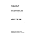
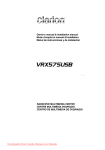
Amplifiers
Amplifiers
2007 Amplifier Line Overview
Clarion amplifiers were designed from the ground
up to compliment one-another in terms of features, performance and design. The 2007 amplifier line takes a three tiered approach to features,
technology and design.
Model
APX2120
APX4240
APX1300
APX2180
APX4360
DPX2250
DPX1800
DPX11500
Class
AB
AB
AB
AB
AB
G
G
G
Description
2-Channel
4-Channel
Mono
2-Channel
4-Channel
2-Channel
Mono
Mono
Power
2 x 60W
4 x 60W
1 x 300W
2 x 90W
4 x 90W
2 x 125W
1 x 800W
1 x 1500W
The entry-level amplifiers offer increased power
production over previous models, as well as featuring a cosmetic theme that integrates with the
top two amp series. The feature set on our entry
level amplifiers was designed to allow installers to
get these amps installed into a vehicle quickly and
tune them without the need for complex instruction manuals. These features allow for elaborate
system design and configuration.
The top two series of amplifiers (Illuminated
and Class G) are designed around a set of features that allow for more accurate installations,
class leading transparency, dynamics, musicality
and efficiency. The APX2180 and APX4360 offer
benchmark sonic transparency, frequency and
phase response and installation / configuration
features. The new DPX amplifiers feature stateof-the-art Class G designs that offer the ultimate
mix of sound quality and efficiency, minimizing
the load on a vehicle's electrical system.
Precise Frequency Selector Electronic
Crossover
The inclusion of an electronic
crossover in an amplifier allows
for efficient setup and configuration of an audio
system. It also allows that amplifier to be used
with factory or after market source units that do
not have electronic crossovers in them. Finally,
the electronic crossover can be used to maximise the performance of the speaker(s) it is powering.
One drawback of a conventional electronic crossover is that it can be difficult to precisely set the
crossover frequency because the potentiometer is
nearly infinitely adjustable. Many crossover controls are only labelled at the top and bottom of its
frequency range, making selecting something in
the middle even more difficult.
Clarion provides a simple and elegant solution
for accurately setting crossover points with our
PFS (Precise Frequency Selector) crossover
adjustment. The potentiometer on the APX2180,
APX4360, DPX2250, DPX1800 and DPX11500
amplifiers has 41 detented positions. Using the
supplied charts, you can select a specific crossover frequency, then to set it, turn the adjustment
potentiometer the according number of clicks,
and you are done.
One of the many benefits of this feature surfaces
when you are building a multi-amp system. With
conventional crossover controls, you could end
up setting a subwoofer amp to 70Hz when you
were aiming for 85Hz and end up at 100Hz on
the mids and highs amp. The result would be a
system that lacks dynamics and sounds muddy.
PFS makes accidental under- or over-lapping of
crossovers a thing of the past.
Input Voltage Selector Gain Control
Conventional gain adjustment
systems have inherent limitations. Because users want a wide sensitivity range
(0.2V to 8.0V for example), a conventional gain
control causes large differences in left and right
64
Amplifiers – Technologies
output - called channel imbalance. This is due to
variances and tolerance limitations on the potentiometer used to make the adjustment.
IVS dramatically reduces channel imbalance by
implementing three gain ranges, 0-0.6v, 0.6-2v, 28v. The result is a reduction in maximum potential
channel imbalance, better imaging and a more
accurate soundstage.
This graph shows the amount of channel imbalance from two identical amplifiers, one with IVS
and one without, The curve with the large bump
is the amplifier without IVS and reaches a maximum channel imbalance of 0.75dB at 0.25% of
maximum gain. The two overlapping curves show
the channel imbalance of an IVS-equipped amp
at the 0.6-2V and 2V-8V settings. The maximum
imbalance is only 0.45dB - half of the non-IVS
amplifier.
what a Clarion customer demands.
The operation of a Class G amplifier is very simple.
Traditional amplifiers use a Class AB output
device topology. Essentially, there are a set of
switching devices (transistors) for the positive half
of the waveform and another set for the negative
half of the waveform. These devices operate
linearly, passing more current through them as
more signal is sent to them. The drawback with
a Class AB topology is that the output devices
operate in their resistive region, rarely fully on
or off. This results in a great deal of heat being
generated and energy wasted. Around a decade
ago, the introduction of Class D amplifiers to the
car audio market showed a marked improvement
in amplifier efficiency at the expense of sound
quality and control. Class D amplifiers operate
by cycling the output devices fully on and off
very quickly, and adjusting the on vs off time to
effect a change in output level. One of the many
drawbacks of Class D amplifiers is that they
require large filtering networks after the output
stage to clean up the signal and remove high
frequency switching noise. Class D amplifiers can
Why not individual gain controls? While individual
gain controls can offer very accurate sensitivity
settings, an installer MUST use an oscilloscope or
voltmeter to properly set these controls for accurate channel to channel output. Clarion has made
every effort possible to reduce installation time
and complexity.
Class G Amplifiers
Amplifier efficiency has never been more important
than it is in today's modern vehicles. Alternators,
batteries and factory wiring are smaller than ever
to produce the lightest and most fuel efficient
vehicles possible at the lowest cost.
Clarion Class G amplifiers are the results of years
of design and testing to offer the optimum balance of sound quality and efficiency - exactly
Class G Amplifier
Red (outside) - Power Supply Voltage
Blue (Sine Wave) - Output Waveform
cause significant electrical interference that can
affect radio reception.
A Class G amplifier is truly the best of both
worlds. Clarion’s Class G DPX amplifiers use
a Class AB audio path with a hybrid Class G
65
Amplifiers – Technologies
multi-voltage power supply. The result is tight,
controlled, dynamic power output with excellent
amplifier efficiency.
How does Class G work? Think of the new
Dodge Hemi or Cadillac Northstar engines. These
engines have the ability to shut down a number
of cylinders to reduce fuel comsumption and
heat generation under light loads. The power
supply of a Class G amplifiers works in exactly
the same way. When you aren’t cranking on the
amp, the power supply rail voltage turns down.
The effect, less current is passed through the
output devices, dramatically reducing wasted
power.
The graph below compares the efficiency of a conventional Class AB 1500W amp to our DPX11500
Strappable Power
The DPX1800 and DPX11500 amplifiers are both
strappable. This means, a pair of amplifiers can be
used on a single voice coil to provide additional
power production for extreme SPL levels. A pair
of DPX1800 amplifiers would produce 1,600W
into a 2 or 4 Ohm load, and a pair of DPX11500
would produce 3,000W into a 2 or 4 Ohm load.
Remote Bass Control
The Clarion DPX1800 and
DPX11500 amplifiers include the
option to connect a Remote Bass Control module. This allows you to install a subwoofer level
control in the front of your vehicle and control the
low frequency system even when connected to a
source unit (factory or aftermarket) that does not
include a subwoofer output level control.
Adjustable Subsonic Filter
Clarion’s new DPX1800 and
DPX11500 amplifiers feature an
adjustable subsonic filter. This filter is adjustable
from 10Hz to 80Hz using a potentiometer on the
end panel of the amplifier.
1500W amplifier. You can see that around 350W
DPX11500 is ~65% efficient, whereas the conventional Class AB is merely 25% efficient. This
means, that the DPX11500 is drawing only 37A
of current, where the Class AB amp would be
drawing closer to 97A of current.
Automatic Impedance Matching
The Clarion DPX1800 and DPX11500 amplifiers
feature an automatic impedance sensing circuit
that allows the amp to produce full power into 1
or 2 Ohm loads. This allows a retailer to sell this
amp to a customer with almost any combination
of speaker impedances, and know that they will
get full power from the amplifier.
This new impedance matching circuit operates
invisibly to the installer. No switches need to be
set, no adjustments need to be made. Connect
the speakers and go.
66
When using subwoofers in vented cabinets with
high tuning frequencies (above 35Hz), physical power handling of the driver may easily be
exceeded. The use of a subsonic filter will limit the
amount of ultra-low frequency information being
passed through to the speaker, as well as reduce
the amount of power the amplifier consumes in
amplifying those low frequencies.
Mixed-Mode Operation
Clarion amplifiers use an inverting circuit that
allows a single 2-channel amplifier to drive multiple satellite speakers in stereo and a subwoofer in
a bridged-mono configuration.
When used in conjunction with passive crossover
components, a Clarion amplifier is capable of
mixed mode operation that can power an entire
audio system.
Amplifiers – Technologies
Multi-Channel Amplifiers
Gold-Plated RCA Connectors
Clarion’s multi-channel amplifiers provide four
channels of amplification from one chassis and
are equipped with on-board high-pass/low-pass
electronic crossovers. This configuration provides maximum system flexibility. For example,
the front channels can drive full-range speakers
with front crossovers off, while rear channels are
set to low-pass and bridged to drive a single
subwoofer. Or the front channels can be set to
high-pass to drive a pair of satellites, and rear
channels set to low-pass to drive a pair of woofers.
Superior conductivity is achieved by using goldplated RCA terminals to minimize the contact
resistance and reduce noise. Moreover, since nonmagnetic gold is not affected by external magnetic
fields, magnetic distortion is also prevented.
The use of a four channel amplifier and their
active crossovers provides quicker setup times
and better efficiency. Passive crossover networks
typically reduce the power arriving at the speakers by 2-4dB.
Amplifier Circuit Information
All of Clarion’s amplifiers contain complex circuitry in both the input and output sections for
noise suppression, fast transient response and
minimum distortion. These circuits include highimpedance differential input stages, and premium
devices with very high slew rates.
Specifications
Clarion has spent a significant amount of time
ensuring that our amplifiers provide the best possible sonic performance. A look at the specifications associated with any of our amplifiers quickly
demonstrates this dedication to purist performance.
Frequency Response
Clarion takes great pride in the fact that our
amplifiers offer frequency response well beyond
the audible spectrum. This ensures perfectly
linear output with no emphasis in any region.
It also moves the phase shift commonly associated with high frequency roll-off out of the
audible range. The APX4360 and APX2180 feature 10Hz-50kHz frequency response within 1dB
- not the usual 3dB rating lesser products use.
High-impedance differential input stages separate the input signal ground from the common
chassis ground. This creates a very effective
ground-loop isolation circuit that reduces the
possibility of charging system noise from entering the signal path. The circuit then compares
the signal information on the shield to that of the
center conductor and eliminates any common
signal (noise), leaving only clear and detailed
music.
This advanced circuit topology ensures that
Clarion amplifiers will accurately reproduce all the
dynamics and subtleties found in today’s digital
recordings. At the same time, noise suppression
circuits work to effectively to eliminate induced
electrical system noise, contributing to maximum
dynamic range.
67
PFS Crossover Charts
Please use the following charts to set the crossover frequency on the APX2180, APX4360 and
DPX2250 amplifiers.
Please use the following charts to set the crossover frequency on the DPX1800 and DPX11500
amplifiers.
Position
Position
Crossover Frequency
1....................................49
2....................................49
3....................................50
4....................................50
5....................................51
6....................................52
7....................................52
8....................................55
9....................................60
10..................................65
11..................................80
12..................................85
13..................................90
14..................................100
15..................................125
16..................................140
17..................................155
18..................................165
19..................................175
20..................................178
21..................................180
22..................................200
23..................................210
24..................................220
25..................................230
26..................................250
27..................................280
28..................................300
29..................................325
31..................................410
32..................................420
33..................................455
34..................................475
35..................................495
36..................................500
37..................................510
38..................................520
39..................................530
40..................................540
41..................................550
68
Crossover Frequency
1..................................24
2..................................24
3..................................24
4..................................24
5..................................24
6..................................25
7..................................27
8..................................30
9..................................33
10................................35
11................................40
12................................43
13................................50
14................................55
15................................60
16................................65
17................................70
18................................75
19................................77
20................................82
21................................86
22................................90
23................................95
24................................100
25................................110
26................................120
27................................125
28................................130
29................................150
30................................155
31................................160
32................................165
33................................175
34................................175
35................................180
36................................180
37................................185
38................................190
39................................195
40................................200
41................................200
DPX Amplifier Error Codes
The APX2180, APX4360, DPX1800 and DPX11500 amplifiers feature computer controlled on-board diagnostics. The chart below outlines the error message and the cause of the message.
Amp Illumination
Red End Panel LED
Blue End Panel LED Cause
ON
OFF
ON
FLASHING
SLOW FLASH
FLASH OUT OF SYNC
FAST FLASH
FLASH IN SYNC
OFF
Short Circuit Detection
3 FLASHES
THREE FLASHES
OFF
Repeated Short Circuit
OFF
FLASHING
OFF
Amplifier Operating Normally
Thermal Protection
Input Voltage Overload
Problem:
Amp is in thermal protection mode
Solution:
- Shut off system and let amp cool down.
- Check speaker load on amp, make sure it does not exceed specification
- Ensure adequate air space around the amplifier
- Ensure end panels (DPX amps) are not obstructed and limiting air flow
Problem:
Input Voltage Overload
Solution:
- Service vehicle electrical system (alternator and voltage regulator)
Problem:
Short Circuit Detection
Solution:
- Check speaker load on amp, make sure it does not exceed specification
- Check all speaker wires for short circuits
- Check all speaker wires for shorts to ground
- Replace speakers with known good units
Problem:
Repeated Short Circuit
Solution:
Resolve Short Circuit problem, disconnect amp for 15 minutes to reset.
69
Amplifiers - Specifications
DPX11500
DPX1800
1 CHANNEL CLASS G MONO AMPLIFIER
1 CHANNEL CLASS G MONO AMPLIFIER
• Input Voltage Selector Input Stage
• Precise Frequency Selector Crossover
• Adjustable High/Low-Pass Crossover
(30Hz to 250Hz, 12 dB/octave)
• Adjustable Subsonic Filter (10Hz to 50Hz)
• Variable Bass Boost Control (0 to 15dB, 30-125Hz)
• Strappable
• Auto Impedance Selection (full power at 1 or 2 Ohms)
• MOSFET Power Supply
• Speaker Level Inputs
• Double Sided FR4PC Board
• On-Board Diagnostics
• Gold-Plated RCA/Speaker/Power Connectors
• Illuminated Amplifier Shroud
Specifications
Number of Channels
Frequency Response (±1.0dB)
Signal-to-Noise Ratio (CEA-2006)
THD@ Rated Output
Input Sensitivity
Specifications
Number of Channels
Frequency Response (±1.0bB)
Signal-to-Noise Ratio (CEA-2006)
THD@ Rated Output
Input Sensitivity
High Level Input Sensitivity
Bass Boost
Power Output @ 1 Ohm (CEA-2006)
Power Output @ 2 Ohms (CEA-2006)
Power Output @ 4 Ohm (CEA-2006)
Dimensions (l x w x h)
70
1
16 Hz to 150Hz
72 dB
<0.1 %
0.2 to 0.6 V
0.6 to 2.0V
2 to 8V
0.4v to 1.2V
1.2 to 4V
4 to 16V
0 -15dB @ 45Hz
1500W
1500W
800W
21-1/4" x 12" x 2 -7/8"
High Level Input Sensitivity
Bass Boost
Power Output @ 1 Ohm (CEA-2006)
Power Output @ 2 Ohms (CEA-2006)
Power Output @ 4 Ohm (CEA-2006)
Dimensions (l x w x h)
1
16 Hz to 150Hz
> 79 dB
<0.1 %
0.2 to 0.6 V
0.6 to 2.0V
2 to 8V
0.4v to 1.2V
1.2 to 4V
4 to 16V
0 -15dB @ 45Hz
800W
700W
450W
19-1/4" x 12" x 2 -7/8"
Amplifiers - Specifications
DPX2250
APX4360
2/1 CHANNEL CLASS G AMPLIFIER
4/3/2 CHANNEL AMPLIFIER
• Input Voltage Selector Input Stage
• Precise Frequency Selector Crossover
• Adjustable High/Low-Pass Crossover
(50Hz to 550Hz, 12 dB/octave)
• Variable Bass Boost Control (0 to 15dB @ 50Hz)
• Bridgeable
• MOSFET Power Supply
• Speaker Level Inputs
• Double Sided FR4PC Board
• Gold-Plated RCA/Speaker/Power Connectors
• Illuminated Amplifier Shroud
• Input Voltage Selector Input Stage
• Precise Frequency Selector Crossover
• Independant Adjustable Front and Rear High/Low-Pass Crossover
(55Hz to 5.5 kHz, 12 dB/octave with Crossover Frequency
Multiplier)
• Variable Bass Boost Control (0 to 15dB @ 50Hz)
• Bridgeable
• MOSFET Power Supply
• F/R input select switch
• Speaker Level Inputs
• Double Sided FR4PC Board
• Gold-Plated RCA/Speaker/Power Connectors
• Illuminated Amplifier Shroud
Specifications
Number of Channels
Frequency Response (±1.0dB)
Signal-to-Noise Ratio (CEA-2006)
THD@ Rated Output
Input Sensitivity
2
18 Hz to 30kHz
> 80 dB
0.1 %
0.2 to 0.6 V
0.6 to 2.0V
2 to 8V
High Level Input Sensitivity
0.4v to 1.2V
1.2 to 4V
4 to 16V
Bass Boost
0 -15dB @ 45Hz
Power Output @ 4 Ohm Stereo (CEA-2006)
125W x 2
Power Output @ 2 Ohms Stereo (CEA-2006)
200W x 2
Power Output @ 4 Ohm Mono (CEA-2006)
400W x 1
Dimensions (l x w x h)
13-1/4" x 12" x 2 -7/8"
Specifications
Number of Channels
Frequency Response (±.3dB)
Signal-to-Noise Ratio (CEA-2006)
THD@ Rated Output
Input Sensitivity
4
10 Hz to 50kHz
> 93 dB
0.05 %
0.2 to 0.6 V
0.6 to 2.0V
2 to 8V
High Level Input Sensitivity
0.4v to 1.2V
1.2 to 4V
4 to 16V
Bass Boost
0 -15dB @ 50Hz
Power Output @ 4 Ohm Stereo (CEA-2006)
90W x 4
Power Output @ 2 Ohms Stereo (CEA-2006)
160W x 4
Power Output @ 4 Ohm Mono (CEA-2006)
300W x 2
Dimensions (l x w x h)
16" x 12" x 2 -7/8"
71
Amplifiers -Specifications
APX2180
2/1 CHANNEL AMPLIFIER
• Input Voltage Selector Input Stage
• Precise Frequency Selector Crossover
• Adjustable High/Low-Pass Crossover (55Hz to 5.5 kHz, 12 dB/
octave with Crossover Frequency Multiplier)
• Variable Bass Boost Control (0 to 15dB @ 50Hz)
• Bridgeable
• MOSFET Power Supply
• Speaker Level Inputs
• Double Sided FR4PC Board
• Gold-Plated RCA/Speaker/Power Connectors
• Illuminated Amplifier Shroud
Specifications
Number of Channels
Frequency Response (±.3dB)
Signal-to-Noise Ratio (CEA-2006)
THD@ Rated Output
Input Sensitivity
2
10 Hz to 50kHz
> 93 dB
0.05 %
0.2 to 0.6 V
0.6 to 2.0V
2 to 8V
High Level Input Sensitivity
0.4v to 1.2V
1.2 to 4V
4 to 16V
Bass Boost
0 -15dB @ 50Hz
Power Output @ 4 Ohm Stereo (CEA-2006)
90W x 2
Power Output @ 2 Ohms Stereo (CEA-2006)
150W x 4
Power Output @ 4 Ohm Mono (CEA-2006)
300W x 2
Dimensions (l x w x h)
12" x 12" x 2 -7/8"
72
APX1300
1 CHANNEL MONO AMPLIFIER
• Adjustable Low-Pass Crossover
(50Hz to 300Hz, 12 dB/octave)
• Selectable Bass Boost (0dB, 6dB, 12dB)
• MOSFET Power Supply
• Speaker Level Inputs
• Double Sided FR4PC Board
• Gold-Plated RCA/Speaker Connectors
Specifications
Number of Channels
Frequency Response (±.3dB)
Signal-to-Noise Ratio (CEA-2006)
THD@ Rated Output
Input Sensitivity
High Level Input Sensitivity
Bass Boost
Power Output @ 2 Ohm (CEA-2006)
Power Output @ 4 Ohms (CEA-2006)
Dimensions (l x w x h)
1
10 Hz to 300Hz
> 85 dB
<0.1 %
0.2V to 5.5V
2 to 16V
0, 6dB, 12dB
500W x 1
300W x 1
13" x 10-7/8" x 2 -3/4"
Amplifiers - Specifications
APX4240
APX2120
4/3/2 CHANNEL AMPLIFIER
2/1 CHANNEL AMPLIFIER
• Independantly Adjustable Front and Rear High/Low-Pass
Crossovers (50Hz to 300Hz, 12 dB/octave)
• Selectable Bass Boost (0dB, 6dB, 12dB)
• MOSFET Power Supply
• Speaker Level Inputs
• Double Sided FR4PC Board
• Gold-Plated RCA/Speaker Connectors
• Adjustable High/Low-Pass Crossovers (50Hz to 300Hz, 12 dB/
octave)
• Selectable Bass Boost (0dB, 6dB, 12dB)
• MOSFET Power Supply
• Speaker Level Inputs
• Double Sided FR4PC Board
• Gold-Plated RCA/Speaker Connectors
Specifications
Number of Channels
4
Frequency Response (±.3dB)
20 Hz to 30kHz
Signal-to-Noise Ratio (CEA-2006)
> 80 dB
THD@ Rated Output
<0.1 %
Input Sensitivity
0.2V to 5.5V
High Level Input Sensitivity
2 to 16V
Bass Boost
0, 6dB or 12dB
Power Output @ 4 Ohms Stereo (CEA-2006)
60W x 4
Power Output @ 2 Ohms Stereo (CEA-2006)
90W x 4
Power Output @ 4 Ohms Mono (CEA-2006)
200W x 2
Dimensions (l x w x h)
13" x 10-7/8" x 2 -3/4"
Specifications
Number of Channels
2
Frequency Response (±.3dB)
20 Hz to 30kHz
Signal-to-Noise Ratio (CEA-2006)
> 85 dB
THD@ Rated Output
<0.1 %
Input Sensitivity
0.2V to 5.5V
High Level Input Sensitivity
2 to 16V
Bass Boost
0, 6dB or 12dB
Power Output @ 4 Ohms Stereo (CEA-2006)
60W x 2
Power Output @ 2 Ohms Stereo (CEA-2006)
100W x 4
Power Output @ 4 Ohms Mono (CEA-2006)
200W x 2
Dimensions (l x w x h)
10-5/8" x 10-7/8" x 2 -3/4"
73
Processors - EQS746 / MCD360
EQS746
MCD360
1/2-DIN GRAPHIC EQUALIZER/CROSSOVER
3-WAY ELECTRONIC CROSSOVER
• 7-Band Graphic Equalizer
• Front panel selectable Main/Auxiliary Inputs
• Front/Rear output with fader and subwoofer output with subwoofer level control
• Selectable Subwoofer Low-Pass Frequency at 60 or 90 Hz
• 6-Channel/7-Volt RCA Line-Level Output
• Auxiliary input sensitivity
• Blue Illumination
•
•
•
•
•
•
•
•
Specifications
Frequency Response
Signal-to-Noise Ratio
Output Voltage
Center Frequencies
Specifications
Frequency Response
Signal-to-Noise Ratio
High-Pass Frequency Range
Dimensions (w x h x d)
74
10 Hz to 50 kHz
100 dB
7.0 Vrms
50Hz, 125Hz, 125Hz,
315Hz, 750Hz, 2.2kHz,
6kHz, 16kHz
7" x 1-1/8" x 4-1/16"
18 dB/Octave Slope-Variable Crossovers
Front, Rear and Subwoofer Outputs with Level Controls
Built-in Bass EQ
Super-Flexible Design
Remote Subwoofer Level Control
Crossover-Frequency Multiplier Switch
2/4/6 Channels of Input
Separate Front and Rear Crossover Points
10 Hz to 50 kHz
100 dB
32 Hz to 8 kHz, Front
32 to 400 Hz, Rear
Subwoofer Equalizer Center Frequency 25 to 100 Hz
Subwoofer Equalizer Boost
0 to 18 dB
Dimensions (w x h x d)
5-1/2" x 1-3/4" x 5 -1/2"