1
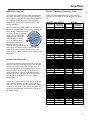
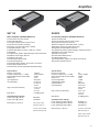
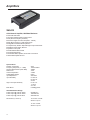
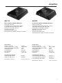
Amplifiers Amplifiers 2010 Amplifier Line Overview With a heritage of power, performance, and quality that spans many decades, Clarion proudly introduces our most sophisticated amplifier line ever. The entire line offers the kind of power and performance that today’s customers demand. Clarion does not ignore the need for an amplifier to look cool, but we put sound quality and performance at the top of our list. We will not for go musical transparency and control for size or a cosmetic feature. Instead, we embrace the latest in power supply technologies to make our amplifiers simultaneously musical, efficient, and compact. Clarion amplifiers are developed to compliment one-another in terms of features, performance, and design. These features exist to help installers complete the integration of these amplifiers into a vehicle faster and more accurately. Likewise, these features also help to improve the performance of the amplifier. XH Series Amplifiers Model XH7110 XH5210 XH5410 Class GH AB AB Class AB AB AB Power @ 4 Ohms 450 Watts X 1 90 Watts X 2 90 Watts X 4 Description Mono 2/1 Channel 4/3/2 Channel Power @ 4 Ohms 300 Watts X 1 60 Watts X 2 60 Watts X 4 2010 Amplifier Technologies Precise Frequency Selector Electronic Crossover PFS The inclusion of an electronic crossover in an amplifier allows the speaker to receive Precise Frequency Selector the musical information that it can produce properly. This means that sound quality from the speaker is improved and power handling in smaller speakers is increased dramatically. One drawback of an electronic crossover which allows the crossover frequency to be adjusted through the use of a potentiometer is that it can be difficult to precisely set the crossover frequency. This is because 64 Clarion provides a simple and elegant solution for accurately setting crossover points with our PFS (Precise Frequency Selector) crossover. The potentiometer on the XH7110, XH5210, and XH5410 amplifiers have 41 detented positions. Using the supplied charts, you can select a specific crossover frequency, then to set it, turn the adjustment potentiometer according number of clicks, and you’re done. One of the many benefits of this feature surfaces when you are building a multiple amplifier system. With conventional (non PFS) crossover controls, you could end up setting a subwoofer amp set to 70Hz when you were aiming for 85Hz and end up at 100Hz on the mids and highs amplifier. The result would be a system that lacks mid-bass dynamics and makes the bass frequencies sound disconnected from the mids and highs. PFS makes under/over-lapping of crossovers history. Input Voltage Selector Gain Control Description Mono 2/1 Channel 4/3/2 Channel XR Series Amplifiers Model XR2110 XR2210 XR2410 the potentiometer is nearly infinitely adjustable. Many crossover controls are only labelled at the top and bottom of their frequency range, making selecting a frequency in the middle of the adjustment range nearly impossible. IVS Conventional amplifier gain (or sensitivity) adjustment systems have inherent limitations. These Input Voltage Selector controls utilize ganged or stacked potentiometers to allow you to match the power production capabilities of the amplifier to the signal strength of the source unit that is feeding it. To allow an amplifier to be used with as many different sources as possible, the sensitivity range should be as wide as possible. Because the gain control uses several potentiometers that are connected together (ganged), the exact resistance of each of these devices may not match the next one. The result is one channel of the amplifier will be louder than the other. This is called channel imbalance. To combat channel imbalance, Clarion has implemented IVS (Input Voltage Selector) technology on the XH7110, XH5210, and XH5410 ampliifers. IVS dramatically reduces channel imbalance by implementing a switch that controls the gain range: 0-0.6v, 0.6-2v, 2-8v. This switch is used in conjunction with a narrow-range adjustable potentiometer for fine tuning. The result is a reduction in maximum potential channel imbalance, improved imaging, and a more accurate soundstage. Amplifiers You might be asking yourself: Why not individual gain controls? While individual gain controls can offer very accurate sensitivity settings, an installer MUST use an oscilloscope or voltmeter to properly set these controls for accurate channel to channel output. At the very least, the installer could tune the system by ear, but this will require many trips from the listening position back to the amplifier. The decision to implement IVS offers the same results but saves the installer time when setting gains, because fewer tools are required. have the ability to shut down a number of cylinders to reduce fuel consumption and heat generation when under light loads. The power supply of a Hybrid Class GH amplifier works in the same way. A micro controller (computer) inside the amplifier controls the output voltage of the power supply. It keeps the voltage just above the output level necessary to reproduce the audio signal. This means that although the output devices are operated linearly, they are almost fully on - it’s the power supply voltage that changes. The result is a significant improvement in efficiency without any effect on the amplifier’s sound quality. Hybrid Class GH Power Supplies Amplifier efficiency has never been more important than it is in today’s modern vehicles. Alternators, batteries, and factory wiring are smaller than ever to produce the lightest and most fuel efficient vehicles possible at the lowest costs. Clarion’s XH7110 amplifier features a Hybrid Class GH power supply. This technology is the result of years of design and testing to offer the optimum balance of sound quality and efficiency - exactly what a Clarion customer demands. The operation of a Hybrid Class GH amplifier is very simple. Traditional amplifiers use a Class AB output device topology. Essentially, there are a set of switching devices (transistors) for the positive half of the waveform and another set for the negative half of the waveform. These devices operate linearly, passing more current through them as more signal is sent to them. The drawback with Class AB topology is that the output devices operate in their resistive region, rarely fully on or off. This results in a great deal of heat being generated and energy wasted. Around a decade ago, the introduction of Class D amplifiers to the car audio market offered a significant improvement in amplifier efficiency at the expense of sound quality and control. Class D amplifiers operate by cycling the output devices fully on and off very quickly. Adjusting the on versus off time effects a change in output level. One of the many drawbacks of Class D amplifiers is that they require large filtering networks after the output stage to clean up the signal and remove high frequency switching noise. Class D amplifiers can cause significant electrical interference that can affect radio reception. Clarion’s Hybrid Class GH technology is truly the best of both worlds. Clarion’s XH7110 amplifier uses a fully analog Class AB audio path. This means tight, controlled, dynamic power output. How does Hybrid Class GH work to improve efficiency if the audio path is all analog? This of the new Dodge Hemi or Cadillac Northstar engines. These engines Strappable Power The XH7110 amplifier is designed and engineered to allow a pair of XH7110 amplifiers to be used on a single voice coil subwoofer to provide additional power production for extreme SPL levels. This is type of interconnection of amplifiers and subwoofer is referred to as “strapping”. Remote Bass Control RBC The Clarion XH7110 amplifier has the provisions to connect an optional Remote Remote Bass Control Bass Control module call the BC2. This allows you to control the amplifiers output level from the front of the vehicle. Unlike some competitors products, this is not a bass boost control. This done for optimum sound quality and performance across the entire frequency range, rather than making the bass sound boomy. Adjustable Subsonic Filter Clarion’s XH7110 amplifier features an adjustable subsonic filter. This filter is adjustable from 10Hz to 80Hz using a potentiometer on the end panel of the amplifier. When using subwoofers in vented cabinets with high tuning frequencies (above 35Hz), physical power handling of the subwoofer may easily be exceeded. The proper use of a subsonic filter will limit the amount of ulta-low frequency information being passed through to the speaker, as well as reduce the amount of power the amplifier consumes in amplifying those low frequencies. 65 Amplifiers Forced Induction Cooling High Impedance Inputs Clarion’s XH-series amplifiers feature forced induction cooling. This is a two-part technology. First, the heatsink design of the amplifier maximizes air flow across the switching devices to hit them with a blast of cool air. Air is then ingested into the core of the amplifier and expelled through the ends of the amp. The second part of Forced Induction Cooling is the computer controlled cooling fan. A thermal sensor connected to the heat sink of the amp combined with programming logic in the amplifiers core decides the appropriate speed for the fan to maximize cooling while minimizing noise. Clarion amplifiers feature high impedance RCA input stages. This allows source unit with low quality high impedance preamp outputs to provide the best possible frequency and phase response while limiting the effect of interconnect reactances on the amplifiers frequency response. Mixed-Mode Operation Clarion 2 and 4 channel amplifiers use an inverting circuit that allows a pair of channels to simultaneously drive multiple satellite speakers in stereo and a subwoofer in a bridged-mono configuration. When used in conjunction with passive crossover components, a Clarion amplifier is capable of mixed mode operation that can power an entire audio system. Differential Inputs High impedance differential input stages separate the input signal ground from the common chassis ground. This creates a very effective ground-loop isolation circuit that reduces the possibility of charging system noise entering the signal path. The circuit also compares the signal information on the shield to that of the center conductor and eliminates any common signal (noise), leaving only clear and detailed music. This advanced circuit topology ensures that Clarion amplifiers will accurately reproduce all the dynamics and subtleties found in today’s digital recordings. At the same time, noise suppression circuits work to effectively to eliminate induced electrical system noise, contributing to maximum dynamic range. Clarion recommends the use of twisted-pair RCA interconnects with our amplifiers. 66 High impedance inputs also allow you to drive multiple amplifiers from a single set of preamp outputs using Y-cables without as dramatic an effect on signal quality. Amplifier Circuit Components Any product is only as good as its weakest link. When Clarion decided to reduce the physical size of the XH and XR series of amplifiers, we knew that this could not be done at the expense of sound quality, performance or reliability. The decision was make to design these amplifiers for the use of surface mount technology (SMT) devices. SMT devices offer improved tolerances as compared to through-hole devices, and better resist electrical interference from RF or EMI noise. The result is an amplifier that costs a little more to produce, but sounds better. Multi-Channel Amplifiers Clarion’s multi-channel amplifiers provide four channels of amplification from one chassis. Each amplifier is equipped with front and rear gain controls and high-/lowpass electronic crossovers. This configuration provides maximum flexibility. A four channel amplifier is the perfect starting point in terms of an amplifier upgrade. This amplifier is most flexible in terms of system expansion. It can be used to drive four full-range speakers, four full-range speakers and a subwoofer, a mid and tweeter set or more. A four channel amp rarely needs to be replaced as a customers system expands over the years, adding value to the purchase. Amplifiers CEA-2006 Compliant Precise Frequency Crossover Chart The Consumer Electronics Association developed the CEA-2006 standard to provide a level playing field in which amplifier power and S/N Ratio specifications can be compared equally. All Clarion power amplifier specifications adhere to the guidelines of the CEA2006 specification. Please use the following charts to set the crossover frequency on the XH5210, XH510, and XH7110 amplifiers. The CEA-2006 specification outlines the following test criteria for amplifier power output testing. Rated power output testing. Rated power shall be measured with all channels driven into a specified load impedance with a distortion level that does not exceed 1%. The amplifier shall produce this power across a specified frequency range (common 20Hz to 20kHz) and be powered by a DC power supply of 14.4V. The S/N Ratio specification is measured with respect to an output equal to 1 Watt, commonly 2V in a mobile audio application. Product Specifications Clarion has invested a significant amount of time and expense ensuring that our amplifiers provide the best possible sonic performance and excellent value. A look at the specifications associated with any of our amplifiers quickly demonstrates this dedication to purist performance. From the extended frequency response to the low S/N Ratios and distortion specifications, Clarion amplifiers provide class leading performance. Clarion takes great pride in the fact that our amplifiers offer frequency response well beyond the audible spectrum. This ensures perfectly linear output with no emphasis in any region. It also moves the phase shift commonly associated with high frequency roll-off out the audible range. XH5210 and XH5410 Position 1 2 3 4 5 6 7 8 9 10 11 12 13 14 15 16 17 18 19 20 21 22 23 24 25 26 27 28 29 30 31 32 33 34 35 36 37 38 39 40 41 Crossover Frequency 49 49 50 50 51 52 52 55 60 65 80 85 90 100 125 140 155 165 175 178 180 200 210 220 230 250 280 300 325 369 410 410 420 455 475 495 510 520 530 540 550 XH7110 Position 1 2 3 4 5 6 7 8 9 10 11 12 13 14 15 16 17 18 19 20 21 22 23 24 25 26 27 28 29 30 31 32 33 34 35 36 37 38 39 40 41 Crossover Frequency 24 24 24 24 24 25 27 30 33 35 40 43 50 55 60 65 70 75 77 82 86 90 95 100 110 120 125 130 150 155 160 165 175 175 180 180 185 190 195 200 200 67 Amplifiers XH-Series Amplifier On-Board Diagnostics The XH7110, XH5210, and XH5410 amplifiers feature a computer controlled on-board diagnostics. This chart below outlines the error messages and the causes of the messages. Amp Illumination ON ON SLOW FLASH FAST FLASH THREE FLASHES Red End Panel LED OFF FLASHING FLASHING OUT OF SYNC FLASH IN SYNC THREE FLASHES Blue End Panel LED OFF FLASHING OFF OFF OFF Cause Amplifier Operating Normal Thermal Protection Mode Input Voltage Overload Short Circuit Detection Repeated Short Circuit Problem: Amplifier is in thermal protection mode. Solution: - Shut off the system and allow the amplfier(s) to cool down. - Check speaker load on amplifier(s), make sure it does not exceed the specifications - Ensure there is adequate air space around the amplifier. - Ensure the end panels are not obstructed and limiting the air flow. Problem: Input Voltage Overload Solution: - Service the vehicle’s electrical system (alternator, voltage regulator, and battery). Problem: Short Circuit Detection Solutiion: - Check speaker load on amplifier, make sure it does not exceed specifications. - Check all speaker wires for short circuits. - Check all speaker wires for shorts to ground. - Replace speakers with known good speakers. Problem: Repeated Short Circuit Solution: - Resolve short circuit problems, disconnect the amplifier(s) for 15 minutes to reset. 68 Amplifers XH7110 XH5210 Mono Amplifier, 850 Watts Maximum 2/1 Channel Amplifier, 340 Watts Maximum Hybrid Class GH Power Supply AB Audio Path IVS (Input Voltage Selector) Gain Control PFS (Precise Frequency Selector) Electronic Low Pass Filter (30Hz - 250Hz) Adjustable Subsonic Filter Variable Bass Boost Control (0 -15dB, 30 - 125Hz) Strappable Complimentary Sanken Triple Darlington Output Transistors MOSFET Power Supply Devices Speaker Level Inputs Double Sided FR4PC Board On-Board Diagnostics Gold-Plated RCA, Speaker, and Power Connections Illuminated Amplifier Shroud Remote Bass Control Ready (BC2 Sold Separately) Class Class IVS Specifications Number of Channels Frequency Response (+/- 1.0dB) Signal to Noise Ration (CEA-2006) Noise Floor Input Impedance Input Sensitivity Specifications Number of Channels Frequency Response (+/- 1.0dB) Signal to Noise Ration (CEA-2006) Noise Floor Channel Separation THD@ Rated Output Input Impedance Input Sensitivity Bass Boost 1 (Mono) 10Hz to 230Hz >63dB <1mV 22k Ohms 0.2 to 6.0V 0.6 to 2.0V 2 to 8V 0.4 to 1.2V 1.2 to 4V 4 to 16V 0-15dB @ 45Hz CEA-2006 Power Ratings: Power Output @ 2 Ohms Power Output @ 4 Ohms 850 Watts 460 Watts Dimensions (L X W X H) 16” X 9” X 2 5/8” High Level Input Sensitivity AB Audio Path (Input Voltage Selector) Gain Control PFS (Precise Frequency Selector) Electronic High/Low Pass Filter (50Hz - 5.5kHz) Bass Boost Control (0 -15dB, 45Hz Fixed) Bridgeable and Mixed Mode Operation Complimentary Sanken Triple Darlington Output Transistors MOSFET Power Supply Devices Speaker Level Inputs Double Sided FR4PC Board On-Board Diagnostics Gold-Plated RCA, Speaker, and Power Connections Illuminated Amplifier Shroud Bass Boost 2/1 10Hz to 230Hz >86dB <2mV >70dB 0.05% 33k Ohms 0.2 to 6.0V 0.6 to 2.0V 2 to 8V 0.4 to 1.2V 1.2 to 4V 4 to 16V 0-15dB @ 45Hz With End Caps On CEA-2006 Power Ratings: Power Output @ 4 Ohms Stereo Power Output @ 2 Ohms Stereo Power Output @ 4 Ohms Mono 90 Watts X 2 160 Watts X 2 320 Watts X 1 13 1/4” X 9” X 2 5/8” Dimensions (L X W X H) Without End Caps Off High Level Input Sensitivity 12 1/2” X 9” X 2 5/8” With End Caps On 9 3/4” X 9” X 2 5/8” With End Caps Off 69 Amplifiers XH5410 4/3/2 Channel Amplifier, 680 Watts Maximum Class AB Audio Path (Input Voltage Selector) Gain Control PFS (Precise Frequency Selector) Electronic High/Low Pass Filter (50Hz - 5.5kHz) Bass Boost Control (0 -15dB, 45Hz Fixed) Bridgeable and Mixed Mode Operation Complimentary Sanken Triple Darlington Output Transistors MOSFET Power Supply Devices Speaker Level Inputs Double Sided FR4PC Board On-Board Diagnostics Gold-Plated RCA, Speaker, and Power Connections Illuminated Amplifier Shroud IVS Specifications Number of Channels Frequency Response (+/- 1.0dB) Signal to Noise Ration (CEA-2006) Noise Floor Channel Separation THD@ Rated Output Input Impedance Input Sensitivity Bass Boost 4/3/2 10Hz to 230Hz >86dB <2mV >70dB 0.05% 33k Ohms 0.2 to 6.0V 0.6 to 2.0V 2 to 8V 0.4 to 1.2V 1.2 to 4V 4 to 16V 0-15dB @ 45Hz CEA-2006 Power Ratings: Power Output @ 4 Ohms Stereo Power Output @ 2 Ohms Stereo Power Output @ 4 Ohms Mono 90 Watts X 4 160 Watts X 4 320 Watts X 2 High Level Input Sensitivity Dimensions (L X W X H) 14 3/4” X 9” X 2 5/8” With End Caps On 12” X 9” X 2 5/8” With End Caps Off 70 Amplifers XR2110 XR2210 Mono Amplifier, 400 Watts Maximum 2/1 Channel Amplifier, 200 Watts Maximum Class AB Audio Path Low Pass Filter (30Hz to 300Hz) Selectable Bass Boost (0dB, 6dB, 12dB) MOSFET Power Supply Devices Speaker Level Inputs Double Sided FR4PC Board Gold Plated RCA, Speaker, and Power Connections Class Adjustable Adjustable Specifications Number of Channels Frequency Response (+/- 1.0dB) Signal to Noise Ration (CEA-2006) THD@ Rated Output Input Impedance Input Sensitivity Bass Boost 1 (Mono) 10Hz to 300Hz >70dB <0.1% 22k Ohms 0.2 to 5.5V 0, 6dB, 12dB Specifications Number of Channels Frequency Response (+/- 1.0dB) Signal to Noise Ration (CEA-2006) THD @ Rated Output Input Impedance Input Sensitivity Bass Boost 2/1 20Hz to 30kHz >85dB <0.1% 22k Ohms 0.2 to 5.5V 0, 6dB, 12dB CEA-2006 Power Ratings: Power Output @ 2 Ohms Power Output @ 4 Ohms 400 Watts 300 Watts CEA-2006 Power Ratings: Power Output @ 4 Ohms Stereo Power Output @ 2 Ohms Stereo Power Output @ 4 Ohms Mono 60 Watts X 2 80 Watts X 2 180 Watts X 1 Dimensions (L X W X H) 12 1/2” X 11” X 2 1/4” Dimensions (L X W X H) 7 3/4” X 11” X 2 1/4” AB Audio Path High/Low Pass Filter (30Hz - 300Hz) Selectable Bass Boost (0dB, 6dB, 12dB) Bridgeable and Mixed Mode Operation MOSFET Power Supply Devices Speaker Level Inputs Double Sided FR4PC Board Gold-Plated RCA, Speaker, and Power Connections 71 Amplifiers XR2410 4/3/2 Channel Amplifier, 400 Watts Maximum Class AB Audio Path High/Low Pass Filter (30Hz - 300Hz) Selectable Bass Boost (0dB, 6dB, 12dB) Bridgeable and Mixed Mode Operation MOSFET Power Supply Devices Speaker Level Inputs Double Sided FR4PC Board Gold-Plated RCA, Speaker, and Power Connections Adjustable Specifications Number of Channels Frequency Response (+/- 1.0dB) Signal to Noise Ration (CEA-2006) Input Impedance Input Sensitivity Bass Boost 4/3/2 20Hz to 30kHz >85dB 22k Ohms 0.2 to 5.5V 0, 6dB, 12dB CEA-2006 Power Ratings: Power Output @ 4 Ohms Stereo Power Output @ 2 Ohms Stereo Power Output @ 4 Ohms Mono 60 Watts X 4 800 Watts X 4 180 Watts X 2 Dimensions (L X W X H) 12 1/2” X 9” X 2 5/8” 72 Amplifers EQS746 MCD360 1/2-DIN Graphic Equalizer with Crossover 3-Way Electronic Crossover 7-Band Graphic Equalizer Panel Selectable Main/Auxiliary Inputs Front/Rear Outputs with Fader and Subwoofer Output with Subwoofer Level Control Selectable Subwoofer Low-Pass Frequency at 60 or 90Hz 6-Channel/7 Volt RCA Line Level Output Auxiliary Input Sensitivity Blue Illumination 18dB/Octave Front Front, Specifications Power Source Frequency Response Signal to Noise Ratio Output Voltage Center Frequencies Specifications Power Source Frequency Response Signal to Noise Ratio Separation High Pass Frequency Range Dimensions (L X W X H) 14.4V DC 10Hz to 50k Hz >100dB 7.0V RMS 50Hz, 125Hz, 315Hz, 750Hz, 2.2k Hz, 6k Hz, 16k Hz 7” X 1 1/8” X 4 1/16” Slope-Variable Crossovers Rear, and Subwoofer Outputs with Level Controls Built-in Bass Equalizer Super-Flexible Design Remote Subwoofer Level Control Crossover-Frequency Multiplier Switch 2/4/6 Channel Inputs Separate Front and Rear Crossover Points Subwoofer Equalizer Center Freq. Subwoofer Equalizer Boost Output Voltage Output Impedance Input Impedance Crossover Slope Rate Crossover Characteristics Output Gain Distortion 14.4V DC 10Hz to 50k Hz >100dB 60dB 32Hz to 8k Hz, Front 32Hz to 400Hz, Rear 25Hz to 100Hz 0 - 18dB 5.0V RMS 100 Ohms 20k Ohms 18dB/Octave Butterworth 1:2 (+6dB) 0.001% THD @ 1V Dimensions (L X W X H) 5 1/2” X 1 3/4” X 5 1/2” 73