1
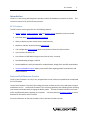
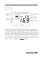
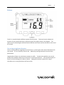
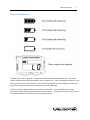
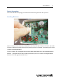
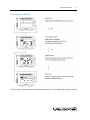
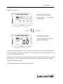
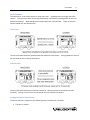
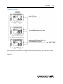
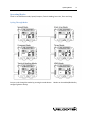
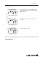
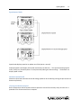
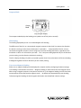
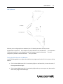
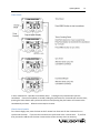
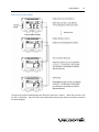
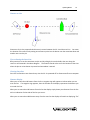
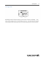
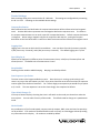
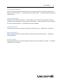
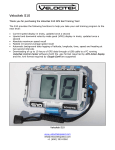
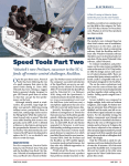
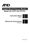
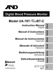
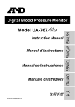
SC-1 Reference Manual
Firmware Version 2.5F (Full Functionality)
SC-1 Features
1
Contents
INTRODUCTION
3
SC-1 FEATURES
BASIC AND FULL FIRMWARE VERSION
3
3
DEVICE OVERVIEW
4
DISPLAYS
BUTTONS
TIPS ON IMPROVING BUTTON RESPONSE
BATTERY LIFE INDICATOR
GPS DATA STORAGE
4
5
5
6
7
DEVICE OPERATION
8
INSERTING BATTERIES
TURNING POWER ON/OFF
SIGNAL ACQUISITION
LOCK FEATURE
SPEED LOCK
TIMEOUT LOCK
LOCKING RELATED TO TIMER EVENTS
CONFIGURING LOCK BEHAVIOR
UNLOCKING PROCEDURE
OPERATING MODES
CYCLING THROUGH MODES
UPPER DISPLAY SELECTION
SPEEDOMETER MODE
COMPASS MODE
TACTICAL COMPASS MODE
VMG MODE
TIMER MODE
START-LINE PROXIMITY MODE
DATA LOGGER MODE
DEVICE SETTINGS
8
9
10
11
11
11
11
12
13
14
14
15
16
17
18
21
23
25
28
29
SC-1 Features
2
UPDATING FIRMWARE
31
PC SOFTWARE PACKAGES
31
CONTROL CENTER
SPEEDPLAY
31
31
MAINTENANCE
32
CONTACT
33
INDEX
34
SC-1 Features
3
Introduction
The SC-1 is a sail training tool designed to provide you with the feedback you need to sail faster. This
instruction manual is for the full firmware version.
SC-1 Features
The full firmware version gives the SC-1 the following features:
•
Speed, compass, tactical compass, VMG and distance to line updated at 2 times a second
•
Start timer with user configurable start sequence
•
Ability to display any two measurements simultaneously
•
Maximum and best 10 second average speed recall
•
User configurable device settings allow customization of select SC1 functionalities
•
Up to 20 hours of battery life
•
Over 20 hours of GPS data storage at record rate of every 2 seconds
•
Data downloading through a USB link
•
Downloaded data is easily formatted for use with Kattack, Google Earth and GPS Action Replay
•
Internet updatable firmware allows you to benefit from ongoing product improvements and
feature additions
Basic and Full Firmware Version
The SC-1 basic firmware is an easy to use, stripped down version of the more powerful but complicated
SC-1 full firmware.
Use the basic firmware if you don't like reading instruction manuals and you only need speed, compass
and distance to line. Use the basic firmware if you are having problems with splashing water unlocking
your buttons and inadvertently changing the display mode. The basic firmware minimizes user input
and is less affected by water splashing on its buttons. You must perform a firmware update to switch
between full firmware to basic firmware.
For more information on the basic firmware refer to the basic firmware manual.
Displays
4
Device Overview
Displays
The upper and lower displays can both be used to display speed, heading, tactical heading, VMG, start
line proximity or timer information. The information shown on each display is made clear by a mode
indicator immediately to the left of the numerical display area. There is no “TIMER” indicator on the
upper display. Timer mode on the upper display is indicated simply by the presence of a colon between
the minutes and seconds. Additionally there is no start line proximity mode indicator in both upper and
lower display. No mode indicators will be displayed in either screen when the device is in start line
mode. Tactical compass mode is indicated by presence of both "COMPASS" and "VMG" indicators.
The first decimal point on the upper display is used as an unlock indicator if any of the lock features are
enabled. The indicator is not displayed if all lock features are disabled.
Buttons
5
Buttons
The SC-1 is controlled by four different capacitive touch sensors. These touch sensors detect the
presence of your thumbs when they are placed on top of the regions shown in the diagram. The
captions on the above diagram indicate how the different touch sensors will be referred to in the rest of
this manual.
Tips on Improving Button Response
If you are having difficulty triggering the touch sensors, try covering the entire area of the button with
your thumb. It is not necessary to press hard. Maximizing coverage improves the touch sensor
performance.
Large droplets of water can cause button response to suffer. To prevent this problem, you can rub
paraffin wax (standard candle wax) on the exterior surfaces of the buttons. This prevents droplets of
water from accumulating on the button surfaces. Wiping off the button surfaces with a rag or
shirtsleeve prior to using the buttons will help as well.
Battery Life Indicator
6
Battery Life Indicator
The battery life of 20 hrs apply for rechargeable nickel metal hydride (NiMH) batteries. Disposable
alkaline batteries will provide approximately 10 hrs of battery life. Also with disposable batteries, there
will be a tendency for the life indicator to remain fully illuminated for most of the battery life and only
drop down to the lower levels when the batteries are nearly exhausted.
The SC-1 will slowly deplete batteries even when it is turned off. Fully charged batteries will be
exhausted in about 100 days when the device is left turned off. For long term storage, remove any one
of the three batteries from the device to prevent this slow drain.
GPS Data Storage
7
GPS Data Storage
Whenever the SC-1 is on and has a GPS signal it records GPS information. GPS information recorded is
longitude, latitude, speed, heading and time.
The SC-1 has room for 20 hours worth of GPS data at a logging rate of 2 seconds. At a logging rate of 4
seconds it can record 40 hours of data and at a logging rate of every 1 second it can record 10 hours of
data.
When the SC1's memory becomes full, the oldest data on the device are automatically deleted to free up
space for new ones. At any point in time, the SC-1 will contain a record of your last several days of
sailing.
Inserting Batteries
8
Device Operation
This section describes everything you need to know before hitting the water with your SC-1.
Inserting Batteries
Open the waterproof case and insert 3 AA batteries into the metal clips on the circuit board. Be careful
to orient the batteries according to the polarity markings on the circuit board. These markings are circled
in red on the photograph above.
The SC-1 will work with rechargeable nickel metal hydride (NiMH) batteries or standard disposable AA
batteries. Disposable batteries will provide approximately 10 hours of life while rechargeable NiMH
batteries will last for approximately 20 hours.
Turning Power On/Off
9
Turning Power On/Off
The SC-1 Power can be turned on and off without opening the case by following the above procedure.
Signal Acquisition
10
Signal Acquisition
The operation of the Velocitek SC-1 relies on low-power radio signals from GPS satellites that orbit the
earth at an altitude of approximately 20,000 km. As a result, the SC-1 must be outdoors with a clear
view of the sky to function properly.
When the SC-1 is first turned on, it must download information from GPS satellites before it can acquire
a GPS solution. The data download process normally takes 1-2 minutes or up to 5 minutes if fresh
batteries have just been installed.
The illustration depicts the GPS signal acquisition process.
Lock Feature
11
Lock Feature
The Velocitek SC-1 uses touch sensors to accept user input. Splashing water can trigger the touch
sensors. To prevent the device from being inadvertently controlled by splashing water the user can
enable lock features. When the device is locked, buttons are non-functional. There are two lock
features Speed Lock and Timeout Lock.
Speed Lock
The unit locks when the device speed exceeds the speed lock value (knots). During speed lock, the unit
will not allow the user to unlock the buttons.
Timeout Lock
The unit locks when the buttons have been inactive for a time period over the timeout lock value
(seconds). During a timeout lock, the unit allows the user to unlock the buttons.
Locking Related to Timer Events
The device will lock in response to the following events if timeout lock is enabled:
•
The timer is started
Lock Feature
•
12
The timer is synchronized
Configuring Lock Behavior
Lock behavior can be customized by configuring device settings.
be configured independently.
The speed lock and timeout lock can
Lock Feature
13
Unlocking Procedure
When the device is in timeout lock the device can be unlocked by pressing plus, minus then the plus
button quickly as shown in the above diagram. When the device is in speed lock the device cannot be
unlocked.
Operating Modes
14
Operating Modes
The SC-1 has 6 different modes, Speed, Compass, Tactical Heading, Start-Line, Timer and Vmg.
Cycling Through Modes
You can cycle through the modes by pressing the mode button. Modes can be enabled/disabled by
configuring device settings.
Operating Modes
15
Upper Display Selection
Speed, heading, tactical heading, distance to line, start timer and VMG can all be displayed in the upper
display. The upper display can be selected by changing the lower display to the desired mode and
pressing the up button.
Operating Modes
16
Speedometer Mode
Speed mode displays speed at an update rate of 2Hz (twice a second).
Displayed speed is the Doppler shift speed measured by the GPS unit. The speed can be displayed in
knots, miles/hour, kilometers/hour or meter/second by editing the device settings. The default is to
display speed in knots.
Maximum Speed Recall
Maximum speed and maximum 10 second average speed can be recalled by pressing the plus and minus
buttons respectively.
Clearing the Maximum Speed
Both instantaneous and 10 second maximum speeds are cleared from memory every time the SC-1 is
powered off or disconnected from a computer.
Operating Modes
17
Compass Mode
The compass mode displays the heading at an update rate of 2Hz (twice a second).
GPS Heading
The heading displayed by the SC-1 is the GPS Doppler shift heading.
The difference of the SC-1 to a conventional magnetic compass is that the SC-1 measures the direction
the device is moving in rather than the direction it is pointed in. A major benefit of the SC-1 over a
conventional magnetic compass is that it will give you accurate heading information, regardless of the
orientation in which it is mounted on your boat. SC-1's compass reading depends only on the direction
you are moving, not the direction the device is pointing.
The SC-1 displays heading only when your speed is greater than 1 knot, otherwise it will show a heading
of 0 degrees regardless of which direction you are actually moving.
True versus Magnetic Heading
Either true or magnetic heading can be displayed in compass mode by configuring the device settings.
True heading is referenced to true north. Magnetic heading is referenced to the local magnetic north.
When using a magnetic compass in conjunction with the SC-1, the magnetic heading is useful since both
measurements will be referenced to magnetic north. By default the compass displays true heading.
To display magnetic heading the local magnetic declination must be defined in device settings.
Operating Modes
18
Tactical Compass Mode
In Tactical Compass mode, the SC-1 displays your heading relative the wind direction stored on the SC-1.
To adjust the wind direction to increase the tactical heading, hold the PLUS button. To adjust the wind
direction to decrease the tactical heading, hold the MINUS button.
Operating Modes
19
Tactical Heading Explained
Tactical heading is the heading relative the wind direction. When sailing by the tell-tales the tactical
heading should be equivalent angles on both tacks.
This makes wind shifts easy to identify. If you're trimming by your telltales and you start seeing smaller
numbers on the tactical compass display you know that you have been lifted, regardless of which tack
you are on.
Once you have identified a wind shift using the SC-1's tactical compass mode, you can adjust the
reference wind direction to account for the shift without leaving the tactical compass mode.
Defining the Wind Direction in Tactical Compass Mode
The reference wind direction stored on the SC-1 is used as a basis for calculating heading to wind in
tactical compass mode as well as VMG in VMG mode.
The wind direction can be defined in tactical compass mode by sailing upwind and tacking several times
while making adjustments to the indicated heading to wind until the same number is seen on both tacks.
Operating Modes
20
Using the Tactical Compass to Identify Wind Shifts
The above sequence shows how you would use the SC-1 to identify a lift while sailing upwind on port
tack. The boat in the example sails at 40° to the wind when trimmed using telltales.
1
Imagine the wind clocking 25° to the left, lifting you on port tack and causing your leeward jib
telltale to flutter. While real wind direction has changed by 25° the reference wind direction
stored on the SC-1 remains unchanged.
2
Re-trim according to your tell-tales. In doing this you will head up until your boats real heading to
wind is 40°, the same as it was before the wind shift. At this point your indicated heading to wind
will only be 15° though because the reference wind direction stored on the SC-1 will still be aligned
with the pre-shift wind direction.
3
Increase your indicated heading back to its pre-shift value. In doing so you will be realigning the
reference wind direction stored on the SC-1 with the actual wind direction. This will prepare you
to spot the next wind shift.
Operating Modes
21
VMG Mode
In VMG Mode the SC-1 shows your Velocity Made Good based on a wind direction you have defined.
The display is updated at 2Hz (twice a second). The wind direction is defined by pressing the plus and
minus buttons in VMG mode. Holding the plus button increases the angle and holding the minus
button decreases the angle. Release the button to define the displayed direction as the new wind
direction.
Determining Wind Direction
Easiest way to determine wind direction is by sailing straight downwind and reading the compass reading
on the SC-1 then adding 180 degrees. You can also sail to irons and read the heading. The VMG
reading will provide you with meaningful information even if you are off by a few degrees.
Operating Modes
22
VMG Explained
Whether you are sailing upwind or downwind, the SC-1 breaks your boat's velocity into two
perpendicular components. One component is perpendicular to the wind direction. This component
is effectively wasted as it is not helping you make any progress upwind or downwind. The other
component is parallel to the wind direction. This is your VMG.
Tuning the Wind Direction in VMG Mode
Use the following guidelines to adjust the wind direction programmed on the SC-1 when you are sailing
upwind:
•
If the indicated VMG seems like it's consistently higher on starboard tack, increase the value of
the programmed wind angle.
•
If the indicated VMG seems like it's consistently higher when you are on port tack, decrease the
value of the programmed wind angle.
Operating Modes
23
Timer Mode
In timer mode the SC-1 provides a countdown timer. Pressing the minus button will start the
countdown. Once the countdown is started, holding the plus button for 3 seconds will reset the timer,
pressing the minus button will synchronize the timer and pressing the plus button will increment the
countdown by a minute. When the timer expires it resets.
Classic Start Scenario
For a classic dinghy start, start the timer at the 5 minute horn then wait for the 4 minutes horn to
synchronize the timer. If you miss the 4 minute horn synchronize at the 1 minute horn. If you find
that you need to add time to the timer increment the minute as many times as necessary.
Operating Modes
24
Button Locking
In timer mode when the timer is started or synchronized the buttons lock, if the timeout lock is enabled.
This is to prevent unintentional button pressing after the timer has started or been synchronized. You
must follow the unlock procedure to unlock the buttons to use the button after these events.
Configuring Countdown
The start sequence can be configured by selecting sync points in device settings. For example, a classic
dinghy start with a start horn at 5 minutes followed by horns at 4, and 1 minutes is defined by selecting
5, 4, 1 sync points. The timer will start from and reset to the highest sync point. Then the timer will
synchronize to subsequent sync points. The classic dinghy start sequence will start from and reset to
5:00 and will synchronize to 4:00 and 1:00.
Beeping
The device beeps multiple times before each minute mark during the countdown. The number of
beeps before each minute mark corresponds to the minute remaining. For example, when there are
three minutes remaining, the SC-1 will beep three times and when there are two minutes remaining the
SC-1 will beep twice.
The unit will beep one long followed by 3 short beeps at 1 minute 30 seconds remaining. 3 short beeps
at 30 seconds and 2 short beeps at 20 seconds.
Beginning when there are 10 seconds remaining in the countdown, the SC-1 will beep once every
second. Beginning when there are five seconds remaining in the countdown, the SC-1 will beep twice
every second. When the timer expires the device will beep continuously for three seconds.
Operating Modes
25
Start-Line Proximity Mode
The start-line proximity mode displays the distance to start-line in meters. When the start-line is not
set “SEt” is displayed. Start-line ends can be defined by using the plus and minus buttons as shown in
the above diagram.
Operating Modes
26
Distance to Line
Distance to line is the perpendicular distance in meters between the SC-1 and the start-line. You enter
the location of the start-line by setting one reference point into the device near the committee boat and
another one near the pin.
Tips on Setting the Start-Line
Best practice is to set the committee and pin end by sailing by the marks before the race along the
start-line as illustrated in the above diagram. The location stored as the end is the location at the time
when the plus or minus button is pressed and countdown is started.
Clearing Start-line
Start-line end locations are cleared every time the SC-1 is powered off or disconnected from a computer.
Distance Display
When you are less than 100 meters from the line a negative sign will appear to indicate when you are
over the line. If no negative sign appears, then the number on the display represents the distance you
are under the line.
When you are more than 100 meters from the line the display simply shows your distance from the line
with no indication of what side of the line you are on.
When you are more than 1000 meters away from the start line the display will switch to displaying “Far”.
Operating Modes
27
Accuracy
The accuracy of the start distance to line provided by the Velocitek SC-1 varies from 0.75 to 3 meters
depending on the number of GPS satellites in view and the location of those satellites in the sky.
Operating Modes
Data Logger Mode
By disabling all modes in the device settings, you can use the SC-1 strictly as a data logger. In this
mode, the device displays “OFF” in the lower display at all times. This mode allows you to log GPS
tracks during races while conforming to any class rules that prohibit electronic or GPS instruments.
28
Device Operation
29
Device Settings
Device settings allow you to customize the SC-1 behavior. The settings are configurable by connecting
the SC-1 to a PC. Following are the available device settings.
Compass Declination
When defined to the local declination the compass measurement will be referenced to local magnetic
north. Positive declination represents west and negative declination represents east. To reference
the compass measurement to true north, input 0 for compass declination. Default compass declination
is 0 degrees. When using a magnetic compass in conjunction with the SC-1, setting the compass
declination to the local declination is useful since both instruments will be referenced to magnetic north.
Logging Rate
Logging rate is the rate at which the SC1 records data. User can select from 1Hz (once every second),
1/2Hz (once every 2 seconds), and 1/4Hz (once every 4 seconds). The default logging rate is 1/2Hz
Speed Display In
Speed can be displayed in 4 different units of measurement, knots, miles/hour, kilometers/hour and
meters/second. The default unit of measurement is knots.
Beep Enabled
Checking the box enables audible beeping. Beeping is enabled by default.
Start Sequence Sync Points
The timer resets to the largest enabled sync point. Once the timer is running, synchronizing it will
cause it to jump to the next lowest sync point. Sync points should be set at the times when you expect to
receive signals from the Race Committee. For a classic dinghy start sequence you would set sync points
at 5, 4 and 1. The start sequence is set to the classic dinghy start sequence be default.
Timer Mode Changes To
If the top or bottom display is showing the timer it will switch to the mode you choose here when the
timer expires. You can select from any of the modes. The default mode to change to is speedometer
mode.
Modes Enable
Any combination of the 5 modes speed, compass, tactical compass, VMG, timer and start line proximity
can be enabled. If all modes are disabled the device will act strictly as a data-logger without providing
any information on the display. All modes are enabled by default.
Device Operation
30
Start line Mode Changes To
If the top or bottom display is showing the start line mode it will switch to the mode you choose here
when the start timer expires. You can select from any of the modes. The default mode to change to is
compass mode.
Timeout Lock Enabled
Checking the box enables timeout lock. When enabled, the SC-1 locks when the buttons have been
inactive for a time period over the timeout lock value (seconds). During a timeout lock, the unit allows
the user to unlock the buttons. By default timeout lock is disabled.
Timeout Lock Value
Time without any user input required in seconds for the device to lock. Default value is 20 seconds.
Speed Lock Enabled
When enabled, the buttons lock when the device speed is above the speed lock value. Speed lock is
enabled by default.
Speed Lock Value
The threshold speed in knots at which the device buttons will lock if speed lock is enabled. The default
speed lock value is 2.0 knots.
Updating Firmware
31
Updating Firmware
Firmware is the program that runs on the SC-1’s microprocessor to control how it operates.
Periodically Velocitek releases new versions of firmware to add functionality to the SC-1. These
updates are designed to either improve your device's performance or to tailor its functionality towards a
specialized application. To perform firmware updates you must connect your SC-1 to a PC with
Velocitek Software Package. To switch between Basic to Full firmware a firmware update is required.
PC Software Packages
There are two PC software packages available from Velocitek. To download GPS data, configure device
settings and update firmware you must install a Velocitek software package and connect the SC-1 to a
PC. To find out more on PC software packages, please visit the following websites and refer to the
corresponding manuals.
Control Center
Control Center allows the user to download GPS data, customize device functionality and perform
firmware updates on the GPS devices. The software is compatible with the S10, SC-1 and SpeedPuck.
GPS Action Replay, a GPS data replay software, is also bundled with the software which can be launched
to replay your sessions.
The Control Center has all the basic features required to deal with a single Velocitek device. If you
organize weekly races with multiple Velocitek devices, we strongly recommend trying out SpeedPlay
which was designed to facilitate GPS data download from multiple devices.
http://www.velocitek.com/products/controlcenter
SpeedPlay
Our customers told us that they love watching GPS replays of their races... but they hate the hassle of
downloading GPS data from a bunch of GPS devices one by one and then spending hours fiddling around
trying to format the data into a coherent race replay.
Velocitek SpeedPlay is our response. This software is designed from the ground-up to make the whole
process of downloading data from a group of GPS devices, formatting the data into a race replay and
then watching the replay as fast and pain free as possible.
http://www.velocitek.com/products/speedplay
Maintenance
32
Maintenance
To ensure your SC-1's enclosure remains watertight and the electronics are not destroyed by corrosion,
please take the following precautions:
Store your SC-1 with the latches undone and the enclosure partially open. This leaves the gasket
decompressed and allows it to expand. This ensures that it will fit tightly when the enclosure is latched
and fully closed.
If you ever see signs that water is leaking inside the SC-1's enclosure please contact Velocitek
immediately at (800)-693-1610 or [email protected] to arrange for your device to be repaired and
made watertight again. If ignored for an extended period of time, a leaky enclosure will wreck your
SC-1
Contact
Contact
Mail:
Velocitek, LLC
271 B Kahiko St.
Paia, HI 96779
USA
Fax:
+1-650-618-2679
Phone:
Calls will be answered 9AM ~ 6PM, Hawaiian Standard Time (GMT-10)
US and Canada:
+1-800-693-1610
International:
+1-650-362-0499
Email:
[email protected]
Website:
http://www.velocitek.com
Forum:
http://www.velocitek.com/forums/
Support:
http://www.velocitek.com/support
33
Index
34
Index
B
O
Battery Life .......................................................................... 6
Beep Enabled .................................................................... 29
Buttons ................................................................................ 5
Operating Modes .............................................................. 14
C
PC Software Packages ....................................................... 31
Clearing Start-line .............................................................. 26
Clearing the Maximum Speed ........................................... 16
Compass Declination ......................................................... 29
Compass Mode .................................................................. 17
Contact .............................................................................. 33
Control Center ................................................................... 31
Cycling Through Modes ..................................................... 14
S
D
Data Logger Mode ............................................................. 28
Device Settings .................................................................. 29
Displays ............................................................................... 4
Distance to Line ................................................................. 26
G
GPS Data Storage ................................................................ 7
GPS Heading ...................................................................... 17
I
Inserting Batteries ............................................................... 8
L
P
Signal Acquisition .............................................................. 10
Speed Display In ................................................................ 29
Speed Lock ........................................................................ 11
Speed Lock Enabled ........................................................... 30
Speed Lock Value .............................................................. 30
Speedometer Mode .......................................................... 16
SpeedPlay .......................................................................... 31
Start line Mode Changes To .............................................. 30
Start Sequence Sync Points ............................................... 29
Start-Line Proximity Mode ................................................ 25
T
Tactical Compass Mode..................................................... 18
Tactical Heading Explained ................................................ 19
Timeout Lock ..................................................................... 11
Timeout Lock Enabled ....................................................... 30
Timeout Lock Value ........................................................... 30
Timer Mode ....................................................................... 23
Timer Mode Changes To ................................................... 29
Tips on Improving Button Response.................................... 5
True versus Magnetic Heading .......................................... 17
Turning Power On/Off ......................................................... 9
Lock Feature ...................................................................... 11
Logging Rate ...................................................................... 29
U
M
Unlocking Procedure ......................................................... 13
Updating Firmware ........................................................... 31
Upper Display Mode Selection .......................................... 15
Maintenance ..................................................................... 32
Maximum Speed Recall ..................................................... 16
Modes Enable .................................................................... 29
V
VMG Explained .................................................................. 22
VMG Mode ........................................................................ 21