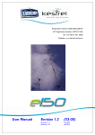
1
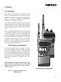
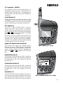
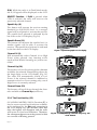
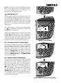
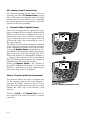
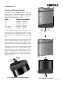
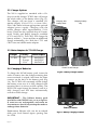
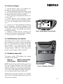
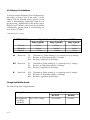
M A X I M I Z I N G
Y O U R
P E R F O R M A N C E
A T
S E A
Instruction Manual
M
A
N
U
A
L
Simrad Axis
Handheld VHF Radio
III
© 2004 Simrad Ltd
The technical data, information and illustrations contained in this publication were to the best of our knowledge correct at the time of going to print. We
reserve the right to change specifications, equipment, installation and maintenance instructions without notice as part of our policy of continuous development and improvement.
No part of this publication may be reproduced, stored in a retrieval system or transmitted in any form, electronic or otherwise without prior permission
from Simrad Ltd.
No liability can be accepted for any inaccuracies or omissions in the publication, although every care has been taken to make it as complete and accurate
as possible.
IV
Part No. E02066 Issue 4.0 12/05/04 CR
CONTENTS
1. GENERAL
1.1
1.2
1.3
Introduction
Technical Specification
Licensing
2. OPERATION
2.1
2.2
2.3
Location of Controls
Operation - 150
Operation - 200/250
2.3.1 The Function Key
3. BATTERY USE
3.1
3.2
3.3
3.4
3.5
3.6
3.7
3.8
Removal, Fitting & Options
Charger Options
Mains Adaptors for Drop-In Chargers
Charging of Batteries
Notes on Charging
200/250 Battery Level Indicator
150 Battery Status LED
Battery Life Guidelines
4. ANTENNA & ACCESSORY SOCKET
4.1
4.2
Antenna
Accessory Socket (150 & 250 only)
5.1
5.2
5.3
5.4
5.5
Spares & Accessories
Transmission Range
Frequency of Channels
Troubleshooting
Service & Warranty
5. APPENDIX
V
1 GENERAL
1.1 Introduction
The Simrad Axis waterproof handheld VHF
radio is manufactured in our modern factory
facilities in the UK. The radio was designed to
meet or exceed stringent International
Regulations including EN301 178.
In addition Simrad GMDSS specification
radios conform to Pan European specification
ETS300 225 for the use of radios for Safety at
Sea, including waterproofing to IP67/68 standard.
Please note that regulations vary from country
to country. Simrad sets are also approved
specifically by the countries in which they are
sold. Consequently, there may be differences in
the programming of sets bought in different
countries, and therefore in their associated
manuals. If using outside the country of purchase, it is vital to check that the set conforms
to local regulations before use.
HI LO
Thank you for choosing Simrad.
HI LO
BAT VOL SQ SIG
LO
Simrad operate a policy of continual development and reserve the right to alter and
improve the specification of their products
without notice.
VOL
SIG
Rx
VOL
D/W
M+
D/W
16SQ
SQ
M+
SQ
CHF
MS
AS
CH
F
AXIS200
AS
AXIS200
If you are pleased with your radio, we hope
you will be interested in our range of marine
electronic equipment, which is manufactured
to the same high standards as Axis. Please contact your nearest Simrad Agent for a catalogue
showing our increasing range of high-tech navigational instruments, autopilots and VHF
radio sets.
Simrad waterproof handheld VHF
Axis® is a registered trademark of
Simrad Ltd.
Page 7
1.2 Technical Specification
Electrical
Channel Capability (Axis200)
55 international channels 1–28, 60–88.
UK : includes M (previously 37) and M2.
USA : includes 0, 29, 89, 75, 76, Wx1–10 receive only.
Scandinavia : leisure or fishing channels as appropriate.
Canada : Canadian and USA channels.
(250)
As 200 plus up to 16 private channels may be
programmed.*
(150)
16 channel capability – channels 06, 16 and 67 are
programmed as standard. Remaining channel spaces may be
programmed with further international or private channels as
specified. The standard channels may also be changed as
required.*
(GMDSS Versions) GMDSS sets are shipped with only simplex channels fitted.
150 GMDSS :
06, 08, 10–17, 67, 69, 71–74
250 GMDSS :
06, 08–17, 67–69, 71–77
Frequency Range
Operating Temperature Range
Output Power
Harmonic and Spurious Emissions
Sensitivity
Selectivity
Intermodulation
Channel Spacing
Blocking
Spurious Response
Audio Output Power
Current Consumption
Weight
155–165Mhz (can be extended to suit market requirements)*.
-20ºC to +60ºC
2 levels, maximum 5 Watts (1 & 5 Watts standard)*.
<.25µW Tx, <1nW Rx
0.5µV for 20 dB SINAD
75 dB (±25 kHz)
75 dB
25kHz (12.5 khz also possible)*
90dB
80dB
Max 1 Watt
Squelched <25mA
Receive
typically 125mA
Transmit
5 Watts
1.4A
1 Watt
0.8A
600g (approx)
* Contact local Simrad Service Agent for further details of channel programming, etc.
Environmental
Waterproof
Drop Resistance
Hermetically Sealed
Ergonomics
Page 8
To a depth of 1m fully submersed, including a 45ºC thermal
shock.
Will withstand a drop from 1M on to a hard surface on any
face.
Will withstand petrol, diesel and other fuel oils.
Is designed to fit comfortably into the hand and be
operated with ease in the worst weather conditions.
1.3 Licensing
Prior to use check the national licensing requirements for operators.
In the UK licence applications and queries should be made to the following authority:
Ship Radio Licensing
Radio Licencing Centre
The Post Office
PO Box 1495
Bristol
BS99 3QS
Website: www.radiolicencecentre.co.uk/rlc
A set may only be operated by or under the supervision of the holder of a Marine Radio
Operator’s Certificate of Competence and Authority to Operate. This is awarded on completion of
the Marine Short Range Certificate course administered by the Royal Yachting Association:
Royal Yachting Association
RYA House
Ensign Way
Hamble
Southampton
SO31 4YA
Website: www.rya.org.uk
Tel. 0845 345 0400
Holders of the Restricted Certificate of Competence in Radio-telephony (which covers MF/HF
SSB, etc.) do not need a separate VHF certificate.
In the USA licence applications should be made to:
Federal Communications Commission
Gettysburg
Washington DC 20554
PA17325
Website: www.fcc.gov
In Canada licence applications should be made to the regional or district offices of:
Spectrum Direct®
Industry Canada
Website: http://sd.ic.gc.ca/engdoc/main.jsp
In all other countries, please contact your regional authority for information.
Page 9
2 OPERATION
2.1 Location of Controls
The location of the controls for the 150 and
200/250 are shown in Figures 2.1 and 2.2:
150 –
1
2
3
4
5
6
7
8
9
10
11
On/Off Button
PTT Button
(Accessory Socket)
High/Low Transmit Power Button
Autosquelch On/Off Button
Backlight On/Off (Channel Display)
Channel Selection Knob
Audio Volume Control Knob
(Tx Status LED)
(Battery Status LED)
(Rx Status LED)
200/250 –
1
2
3
4
5
6
7
8
9
10
11
12
13
7
3
On/Off Button
PTT Button
(LCD Screen)
High/Low Transmit Power Button
Audio Volume Up
Audio Volume Down
Dual Watch (D/W)
Squelch Up/Enter Memory
Channel 16
Channel Up/Memory Scan
Squelch Down/Scan Inhibit
Function*/LCD Backlighting
Channel Down/All Scan
* Scanning models only. All functions listed in
italics are secondary functions accessed by
pressing the FUNCTION (F) key first.
8
1
4
2
5
6
9 10 11
AS
Fig 2.1 - 150 schematic
1
4
2
5
3
7
8
6
9
11 12
10
13
AS
Fig 2.2 - 200/250 schematic
Page 10
2.2 Operation – 150
Anti-clockwise
The operation of any of the push buttons or
the channel selector knob is confirmed by an
audible beep from the unit. The operation of
the controls for the 150 and 150 GMDSS is as
follows:
On/Off Button (1)
Pressing this button will turn the radio on and
off. To turn the radio off it is necessary to hold
the button in for two seconds. This prevents the
radio being accidentally switched off.
TURN RADIO OFF
PTT Button (2)
The PTT, or Press-To-Talk, button is used to
switch the radio from receive to transmit.
Unlike other keys, the radio will not beep if this
key is pressed, but the Rx LED (11) will go off
and the Tx LED (9) will illuminate.
If the radio will not transmit when the PTT button is pressed, this may be because the selected
channel is not valid for transmission.
HI LO
TX
BAT
RX
High/Low Transmit Power Button (4)
This button will toggle the transmit power
between the preset maximum level (normally 5
Watts) and low power (normally 1 Watt).
Autosquelch On/Off Button
When pressed, this button will open the
squelch to incoming signals. The squelch setting is preset at the factory to cope with most
operating conditions. If, however, it is found
necessary to change this setting, the following
procedure should be followed :
1. With the radio on, turn the volume control
(8) fully anti-clockwise (Fig 2.3).
2. Turn the radio off.
3. Without adjusting the rotary controls, hold
in the squelch button and turn the radio on.
4. A triple beep will be heard. This will be followed by a series of beeps indicating the
squelch level being set.
5. The setting is from 1 to 8 beeps, with 8 being
fully squelched. When the correct setting is
reached, release the squelch button. The setting
is now stored in the radio.
TURN RADIO ON
HI LO
TX
BAT
RX
RELEASE BUTTON
WHEN CORRECT SETTING IS SELECTED
Fig 2.3 - Setting Autosquelch
Page 11
Backlighting On/Off (6)
This button will illuminate the channel selection window for a period of ten seconds. The
window will re-illuminate for a further ten seconds if a key is subsequently pressed, thus preserving battery life. Pressing this button again
will switch the backlighting off.
Channel Selection Knob (7)
This is a sixteen-position rotary switch used to
select the channels programmed into the radio.
The channel selected is shown in the channel
selection window next to the knob, with each
programmed channel selection being confirmed by a beep. This first position (normally
channel 16) is indicated by a long beep. NB,
although there are sixteen channel locations,
not all of these may have a channel programmed into them.
HI LO
TX
BAT
RX
Fig 2.4 - Tx LED: transmitting on high power
Audio Volume Control Knob (8)
Turn the knob clockwise to increase volume
and anticlockwise to reduce volume.
Tx Status LED (9)
This LED indicates the transmit power status
of the radio:
HI LO
LED
LED
LED
LED
Blinking Receive, high power selected.
Off
Receive, low power selected.
Flashing Transmit, low power selected.
On
Transmit, high power selected
(Fig 2.4).
TX
BAT
RX
Battery Status LED (10)
This shows the charge status of the battery LED Off
LED Blinking
Battery charge okay.
Battery level low (Fig 2.5).
Fig 2.5 - Rx LED: receiving, fully squelched
Rx Status LED (11)
This displays the squelch status of the radio as
follows:
LED Blinking
LED On
Page 12
Fully squelched (Fig 2.5).
Squelch open.
2.3 Operation – 200/250
The operation of any of the push buttons, or
the channel selector knob is confirmed by an
audible beep from the unit. The operation of
the controls for the 200, 250 and 250 GMDSS is
as follows On/Off Button (1)
Pressing this button will turn the radio on and
off (Fig 2.6). To turn the radio off it is necessary
to hold the button in for two seconds, preventing the radio being accidentally switched off.
PTT Button (2)
The PTT, or Press-To-Talk, button is used to
switch the radio from receive to transmit.
Unlike other keys, the radio will not beep if this
key is pressed, but the LCD legend will change
from Rx to Tx , and the bar graph will display
the current battery strength.
HI LO
VOL
VOL
If the radio will not transmit when the PTT button is pressed, this may be because the selected
channel is not valid for transmission. NOTE transmit is also inhibited when the Dual Watch
or Scanning functions are activated.
D/W
16
SQ
CH
M+
MS
SQ
CH
F
AS
High/Low Transmit Power Button (4)
This button will toggle the transmit power
between the preset maximum level (normally
5 Watts) and low power (normally 1 Watt). The
power setting selected will be indicated by
either the HI or LO legend on the LCD display.
Fig 2.6 - Switching On and Off
Audio Volume Up (5)
This button will increase the audio volume in
graduated increments. The volume setting will
be indicated on the LCD display by the bar
graph (Fig 2.7).
HI LO
Rx
Audio Volume Down (6)
This button will decrease the audio volume in
graduated decrements. The volume setting will
be indicated on the LCD display by the bar
graph.
VOL
VOL
VOL
VOL
D/W
16
SQ
M+
SQ
CH
MS
CH
F
AS
Dual Watch (7)
The Dual Watch function enables the radio to
scan between the selected channel and the priority channel (normally channel 16). To activate
Dual Watch mode, select the channel and press
Fig 2.7 - Volume bargraph on LCD display
Page 13
D/W. While the radio is in Dual Watch mode,
the D/W legend will be displayed on the LCD.
REVERT Function - If D/W is pressed when
CH16 is selected, the radio will revert to the
previously selected channel.
HI LO
Squelch Up (8)
This button will increase the receiver muting
threshold (or SQUELCH) level, i.e a stronger
signal will be required to activate the receiver.
The squelch level selected is indicated by the
bar chart on the LCD display (Fig 2.8).
VOL
SQ
Rx
VOL
D/W
16
SQ
M+
Squelch Down (11)
This button will decrease the squelch level, i.e
weaker signals will be able to activate the
receiver. The squelch level selected is indicated
by the bar chart on the LCD display.
SQ
CH
MS
CH
F
AS
Fig 2.8 - Squelch bargraph on LCD display
Channel 16 (9)
Will automatically select Channel 16 on High
Power when pressed. Any function active
(such as Dual Watch, Scanning, etc) will be cancelled.
Channel Up (10)
This button will scroll up through the channels
available, the selected channel being shown by
the large digits on the LCD display (Fig 2.9).
The radio will automatically switch to Low
Power if the selected channel is inhibited to
transmit on the Low Power setting only, even if
High Power is currently selected.
VOL
SIG
Rx
VOL
D/W
16
SQ
M+
SQ
CH
MS
CH
F
AS
Channel Down (13)
This button will scroll down through the channels available as Channel Up (see above).
SIG
VOL
Rx
VOL
2.3.1 The Function Key (12)
(SCANNING MODELS ONLY) Function (F) is
used to access second level functions available,
and is indicated by the F legend appearing in
the LCD display for two seconds. After this
time, the legend will disappear and the radio
will revert to first level functions. Therefore,
the subsequent buttons must be pressed within
two seconds of F being pressed.
Page 14
SIG
VOL
Rx
VOL
Fig 2.9 - Scrolling through channels using CH▲ and
CH▼ buttons
NOTE - Second level functions are only available on scanning versions of the 200 and 250.
On non-scanning versions, the F key is replaced with a backlighting key.
D/W
16
SQ
CH
M+
SQ
MS
CH
F
AS
- Backlighting (F-F)
On scanning models of the 200 and 250, the
LCD display backlighting can be switched on
by pressing F and F again within two seconds.
By keeping F depressed, the radio will step
through the six levels of illumination available
(Fig 2.10). A second press will turn the backlighting off.
HI LO
While the backlighting is activated, the lamp
legend
will be shown on the LCD display.
On all versions, the backlighting will automatically switch off if no button is pressed for ten
seconds or longer. The backlighting will re-illuminate if a button is subsequently pressed.
VOL
SIG
On non-scanning versions, the backlighting
key
– which replaces the F key – must only
be pressed and held once.
Rx
VOL
D/W
16
SQ
M+
SQ
CH
MS
CH
F
AS
Fig 2.10 - LCD backlighting
AS - All Channel Scan (F-Channel Down)
This function enables the radio to scan through
each channel sequentially until a signal is
detected which is above the squelch level set.
Once the signal ends or drops below the
squelch level, the radio will continue scanning.
Pressing Channel Up will step to the next
channel regardless of the signal strength.
Pressing Channel Down or F-Channel Down
will exit Scan mode.
M+ - Memory Enter (F-Squelch Up)
This function will add the currently selected
channel into the Scan Memory. The LCD display will show ‘ENT’ indicating that the channel has been entered into the Scan Memory.
When that channel is subsequently selected, a
legend will be shown on the bottom line of
the LCD display indicating that the channel is
in the Scan Memory (Fig 2.11). Pressing FSquelch Up if the channel is already in the
Scan Memory will remove it from the memory
- indicated by ‘DEL’ appearing on the bottom
line of the LCD display.
VOL
SIG
Rx
VOL
D/W
16
SQ
M+
SQ
CH
MS
CH
F
AS
VOL
SIG
Rx
VOL
D/W
16
SQ
M+
SQ
CH
MS
CH
F
AS
Fig 2.11 - Entering channel into Scan Memory
MS - Memory Scan (F-Channel Up)
This function operates in the same way as the
Scanning function (F-Channel Down), except
that it will only scan channels that have been
entered into the Scan Memory. If no channels
have been entered into the memory, then this
function will not be available.
- Channel Inhibit (F-Squelch Down)
Since the Scanning function operates by stopping on channels where a signal is detected, the
function will lock onto a channel with a lot of
interference noise, or if a channel is transmitting a continuous carrier wave signal. This will
prevent the radio from continuing its scan of
the other channels.
The Inhibit function allows unwanted channels
to be removed from the Scanning function
while remaining available for use on the radio.
Pressing F-Squelch Down will inhibit the current channel – indicated by ‘INH’ appearing on
the bottom line of the LCD display (Fig 2.12).
When that channel is subsequently selected, a
legend will be shown on the bottom line of
the LCD display indicating that the channel is
inhibited from the Scanning function.
Pressing F-Squelch Down if the channel is
already in inhibited will restore it to the Scan
function – indicated by ‘SCAN’ appearing on
the bottom line of the LCD display.
VOL
D/W
16
SQ
M+
SQ
CH
MS
CH
F
AS
VOL
SIG
Rx
VOL
D/W
16
SQ
M+
Mem (F-Channel Up held for two seconds)
VOL
SIG
Rx
SQ
CH
MS
CH
F
AS
This function allows the radio to operate only
on the channels held in the Scan Memory indicated by ‘MEM’ shown on the LCD display. If the Scanning function is selected, it will
operate the same way as the Memory Scan
function.
Pressing CH16 or F-Channel Up held for
two seconds will return the radio to normal
operation.
Page 16
Fig 2.12 - Inhibiting channel from Scan
3 BATTERY USE
SQ
CH
F
AS
The radio comes equipped with a 700- or
850mA-hour NiCad battery pack as standard
(depending on model). All battery types are
housed in an identical enclosure.
Model
Battery Pack Supplied
200
150
250
150 GMDSS
250 GMDSS
NCB700 - 700mAh
NCB850 - 850mAh
NCB850 - 850mAh
NCB850 - 850mAh
NCB850 - 850mAh
AXIS 200
3.1 Removal, Fitting and Options
To remove the battery, lift the release lever situated at the base of the battery pack to the vertical position. Turn this through 180º, and pull
the release lever to withdraw the battery (Fig
3.1).
Although the set is fully waterproof even with
the battery removed, it is recommended that
any moisture on the top of the battery or in the
battery compartment is wiped clear prior to
insertion to prevent the water creating a conductive path between the contacts and reducing battery life.
Fig 3.2 - Release lever in ‘unlocked’ position
SQ
CH
F
AS
AXIS 200
Before inserting a battery, check that the release
lever is in the ‘unlocked’ position (Fig 3.2), i.e.
the textured side of the lever is pointing away
from the recess on the base of the battery pack.
Fig 3.1 - Battery pack removal
Page 17
3.2 Charger Options
The 200 is supplied as standard with a 12v
drop-in trickle charger TCH12 that will accept
the whole radio, or the battery alone (Fig 3.3).
This charger will run from a standard 12v
marine supply (12.6v–15.5v), or from 110v/
220v/240v mains with an appropriate optional
adapter/power supply. Charging with the
trickle charger takes approximately 12–16
hours. There are also optional drop-in Commercial Trickle and Rapid chargers available
(CTC1 and CRC1). The CRC1 will charge the
battery within 11/2 hours and has an additional
charge maintaining slot. Both the CTC1 and
CRC1 have an inbuilt mains adapter.
Charging with
battery fitted
Charging battery
only
HI LO
VOL
VOL
D/W
16
SQ
M+
SQ
CH
MS
CH
F
3.3 Mains Adapters for TCH12 Charger
Charger
TCH12
Country
UK
Europe
USA
Mains Adapter
MAD230:U
MAD230:E
MAD115:A
3.4 Charging of Batteries
To charge the NiCad battery pack, insert the
radio or battery into the charger ensuring that
excess moisture is wiped clear from the three
contacts on the back of the battery pack (Fig
3.4). The TCH12 will constantly trickle charge
the battery even once it is fully charged, thus
ensuring that it is always at full capacity. The
RCH1 will rapid charge the battery until it is
fully charged and will then automatically
switch to trickle charge.
IMPORTANT – The lithium battery pack
(available with GMDSS sets, or as an optional extra) are not rechargeable, and under no
circumstances should any attempt be made to
recharge these batteries.
Replacement lithium cells can be re-ordered
from your local Simrad Agent, quoting Part
No. LTB1.
Page 18
AXIS200
AS
TCH12 Trickle Charger
Fig 3.3 - Battery Charger Options
Battery Contacts
Contacts
Battery
Fig 3.4 - Battery Charging Contacts
3.5 Notes on Charging
1. NiCad battery packs are supplied uncharged and need charging before use.
2. Charge the battery up to full charge when
not in use, although it may lose a proportion of
its charge after some months of storage.
3. Do not charge at temperatures below 0ºC
or above 40ºC.
4. Check battery level indicator during
switch on to determine remaining battery life.
5. Turn off if charging battery while fitted to
Axis.
6. Always try to fully discharge the battery
before recharging – repeated recharging of the
battery while it is partly discharged may create
a ‘memory effect’, preventing the battery
reaching full charge.
7. Dispose of used batteries carefully. The
contents of the batteries are harmful to wildlife.
8. Never expose to a naked flame.
BAT
Tx
Fig 3.5 - 200/250 Battery Level Indicator
3.6 200/250 Battery Level Indicator
The battery level is shown when the radio is
first switched on, and also when transmitting
(Fig 3.5). This indicates the voltage at the battery terminals, not necessarily the charge
stored. Seven or eight bars represent a fully
charged battery, whilst four bars represent a
battery whose charge is almost drained.
HI LO
TX
BAT
RX
3.7 150 Battery Status LED
The battery status LED displays the current
condition of the battery.
LED off :
LED blinking :
Battery level nominal.
Battery level low.
NOTE - When using a lithium battery pack, the
low level battery indicator may flash under
transmit conditions. This does not necessarily
reflect the charge level remaining in the battery,
as it is due to the different voltage characteristics of a lithium battery pack under load.
Fig 3.6 - 150 Battery Status LED
Replacement and spare batteries are available
from your local Simrad Agent. Please quote the
relevant part number.
Page 19
3.8 Battery Life Guidelines
To a large extent, the battery life will depend on
the usage, or Duty Cycle of the radio – i.e the
battery will be drained much quicker, if the
radio is transmitting continually than if it is
just receiving. Additionally, if the radio is set to
High Power (5 Watts*), the power drain will be
considerably greater than if transmitting on
Low Power (1 Watt*).
* Standard power settings
BATTERY PACK
Typical Life of a fully charged pack at 25°C
Duty Cycle Ai
700mAh
850 mAh
Lithium
5.6 hrs
8.0 hrs
> 15 hrs
Duty Cycle Aii
Duty Cycle B
6.7 hrs
9.4 hrs
> 18 hrs
3.2 hrs
4.6 hrs
>8 hrs
Ai
Based on -
5% Transmit at 5 Watts setting of r.f. output power (1.4Amp)
5% Receive at 250mWatts Audio (.25Amp)
90% Receiver squelched (0.025Amp)
Aii
Based on -
5% Transmit at 1Watt setting of r.f. output power (1.1Amp)
5% Receive at 250mWatts Audio (.25Amp)
90% Receiver squelched (0.025Amp)
B
Based on -
10% Transmit at 5Watt setting of r.f. output power (1.4Amp)
10% Receiver at 250mWatts Audio (.25Amp)
80% Receiver squelched (0.025Amp)
Charge Held While Stored
The following data is approximate:
Battery Pack
NiCad Battery
(NCB700/
NCB850)
Page 20
Duration
Up to 50% Charge
At 25 ºC
At 45ºC
4–6 months
4 weeks
4 ANTENNA & ACCESSORY SOCKET
4.1 Antenna
The antenna for the radio is fitted to the unit
via a robust screw fitting to an M8 threaded
socket on the top of the radio (Fig 4.1). This system is more rugged than a traditional BNC
connector, so the radio’s drop-proof integrity is
not compromised by the antenna fixing.
While the radio is drop-proof and very robust,
damage to the antenna such as bending or
kinking may adversely affect the transmission
efficiency of the unit, which may lead to overloading of the power module. Damaged antennae should be replaced immediately.
Replacement antennae can be purchased from
authorised Simrad Service Agents. A full list is
supplied with this unit. Please refer to section
5.1 for more details on spare parts and accessories available.
4.2 Accessory Socket (150 & 250 only)
Fig 4.1 - Antenna fixing
Commercial and GMDSS versions of the radio
(150, 250) have an accessory socket fitted
behind the antenna housing (Fig 4.2). This
socket will accept approved accessories such as
waterproof fistmikes and headsets.
The accessory socket is waterproof, but it has
an additional splash cover to protect the electrical contacts from prolonged exposure to
moisture. Always replace the cover when the
socket is not in use. A coating of silicone or
Teflon grease to the socket is recommended to
assist in protecting the contacts from moisture.
Splash Cover
Always turn the radio off before plugging any
accessory into the socket. It is recommended
that any excess moisture is wiped away to
avoid any problems caused by water shorting
out adjacent contacts.
NOTE - The use of unapproved accessories
with the accessory socket may damage the
radio and invalidate the warranty.
Fig 4.2 - Accessory socket (150/250 only)
Page 21
5 APPENDIX
5.1 Spares & Accessories
NCB700
The following spares and accessories are
available from authorised Simrad Dealers.
A list of dealers is included with this unit.
Please quote the appropriate part number
when ordering.
Spare NiCad Battery
Pack (700mAh)
LTB1
NCB850
Spare Lithium
Battery Pack
Spare NiCad Battery
Pack (850mAh)
ANT1
Spare Antenna
Charging Accessories
TCH12
12v Trickle
Charger
MAD230:U (UK)
MAD230:E (Europe)
MAD115:A (USA)
Mains Adapters for
TCH12
3M
(10 Ft)
HI LO
VOL
BAT VOL SQ SIG
CTC1
LO
Rx
Tx
VOL
D/W
16
SQ
M+
SQ
CH
MS
CH
F
Commercial Trickle
Charger
AS
AXIS200
CRC1
Commercial Rapid
Charger
off
on
Page 22
rear
charge
Battery Charger
CRC
status
charge
Carrying Accessories
HS1
Handstrap
BMT1
LC1
Bulkhead
Mount Plate
Leather
Carrying
Case
BCP1
Leather Belt
Clip c/w
Adapter Plate
ADP1
LYD1
Lanyard
ADP1
Adapter Plate
WB1
SS1
Shoulder
Strap
Aluminium Wall
Mount Bracket
(For use with
TCH12)
FLT1
Flotation Strap
WPSM1:GY
Waterproof Speaker
Mike - Grey
WPSM1:Y
Waterproof Speaker
Mike - Yellow
2.5M coiled cable
Page 23
5.2 Transmission Range
Because VHF signals travel in a straight line
and are not reflected back off the ionosphere as
lower frequency signals are, the range of VHF
signals is limited to ‘line of sight’, beyond
which the other vessel passes behind the curve
of the Earth. Therefore, the range will increase
greatly the higher above sea level the antenna
is, as Figure 5.1 illustrates (assuming maximum transmission power is used):
Fig 5.1 - VHF transmission range
Therefore, the typical range of a handheld
radio such as this one used at sea level will be
approx. 8 km (5 miles). This will increase as
height above sea level increases, or if the other
radio user’s antenna is at a greater height –
note, that the range between the yacht with the
antenna mounted on a 9 m (30 ft) mast and the
handheld user increases to 13–16 km (8–10
miles).
Page 24
5.3 Frequency of Channels
In the UK channels 0 and 00 will only be made available to Coastguard users with written
authorisation.
Page 25
5.4 Troubleshooting
Symptom
Possible Cause
Remedy
Unit will not switch on
* Battery not charged
* Battery not secured correctly
in radio
* Re-charge battery
* Ensure battery is fully
locked in (see section 3.1)
Scan or Memory Scan is
locking on a channel
without a signal
* Noise on the channel is
holding the scan
* Increase squelch level
* Inhibit channel from scan
- 200/250 (see section 2.3)
Dual Watch not being
entered
* Priority channel selected
(normally CH16)
* Select a working channel
Cannot change channel
* Dual Watch (D/W) engaged
* Exit Dual Watch
Certain channel numbers
are not obtainable
* Some channels are restricted
and programmed out depending on country of purchase
* Consult your national
authority for permitted
channels in your region
Will not transmit
* Scanning or D/W function active
* Exit D/W or Scan
Will not transmit on 5W
but OK on 1W
* Low voltage when full transmitting current is drawn
* Some channels are restricted to
low power transmission only
* Battery charge low recharge the battery
* Consult your national
authority
Transmissions persistently
weak
* Damaged antenna
* Replace antenna
These simple checks should be carried out before seeking technical assistance and may save time
and expense.
Before contacting your servicing agent please obtain the radio’s serial number. On 200 & 250 models the software iteration should also be quoted. This is shown in the large digits on the display
for 2 seconds after the radio is turned on.
5.5 Service & Warranty
Your radio should seldom need servicing, although it will benefit from an application of silicone
or Teflon grease to the battery contacts and accessory socket each season. If it is necessary to have
the unit repaired, the warranty card supplied with the unit should have been filled in and sent to
Simrad when the unit was purchased. Please refer to the Warranty Card booklet for more details.
IMPORTANT – The radio is a sealed waterproof unit. To create and maintain its waterproof
integrity it was assembled in a controlled environment using special equipment. The radio is
not a user maintainable unit, and UNDER NO CIRCUMSTANCES should the unit be opened,
except by authorised Simrad Service Agents. Unauthorised opening of the unit will invalidate
the warranty.
Page 26
E02066 Issue 4.0
www.simrad.com
M A X I M I Z I N G
Y O U R
P E R F O R M A N C E
A T
S E A