1
ATAVRMC100
..............................................................................................
Hardware User Guide
Section 1
Introduction ........................................................................................... 1-1
Section 2
Getting Started...................................................................................... 2-4
Section 3
Hardware Description ........................................................................... 3-7
Section 4
Programming ATAVRMC100.............................................................. 4-14
Section 5
Basic Test Program ............................................................................ 5-18
Section 6
Troubleshooting Guide ....................................................................... 6-22
Section 7
Technical Specifications ..................................................................... 7-23
Section 8
Technical Support ............................................................................... 8-24
Section 9
Complete Schematics......................................................................... 9-25
ATAVRMC100 User Manual User Guide
1
7551B–AVR–02/06
Section 1
Introduction
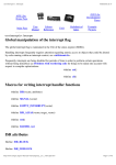
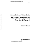
Congratulations on your purchase of the AVR® ATAVRMC100 evaluation kit. This document describes the board included in the ATAVRMC100 starter kit dedicated to
AT90PWM3.
1.1
Overview
The ATAVRMC100 is an evaluation kit dedicated to brushless DC motor control, for
both Hall effect sensor control and sensorless control using Back ElectroMotive Force.
The kit includes an evaluation board, a 3-phase BLDC motor and a demonstration software. It allows users to quickly evaluate the capability of the AVR® microcontroller
AT90PWM3 to control high speed brushless DC motor applications.
The kit can also serve as a development platform. Low cost AVR development tools
make debugging easier, and source codes, written in C, can be easily re-used by developers for their own motor control applications.
ATAVRMC100 User Manual
1
7551B –AVR–02/06
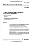
Figure 1-1 . ATAVRMC100
1.2
ATAVRMC100 Features
The ATAVRMC100 provides the following features:
AT90PWM3-16SQ SO32 device (2.7 - 5.5V)
On Board LIN Transceiver Atmel ATA6661
Power bridge for BLDC Motors
Hall Sensor or Sensorless Configuration
Zero Crossing Voltage Detection
Hardware Overcurrent DeteCtion
Motor Supply Voltage Measurement
On-board Voltage Regulator (5V)
AVR Studio® Software Interface(1)
Power-supply Flagged by Green LED
ISP Connector for on-chip In-System-Programming
ISP Connector for Debug Wire
System Clock: Internal RC Oscillator Only
Numerous Access Points for Test
Recommended Voltage Operation from 12V to 16V DC (4A)
ATAVRMC100 User Manual
2
7551B–AVR–02/06
Operating Temperature Range from 0°C to 70°C
Dimension: 75 mm x 55 mm
Notes:
ATAVRMC100 User Manual
1. The AT90PWM3 is supported by AVR Studio®, version 4.11 Service Pack 3 or higher.
For up-to-date information on this and other AVR tool products, please consult our
web site. The newest version of AVR Studio®, AVR tools and this User Guide can be
found in the AVR section of the Atmel web site, http://www.atmel.com.
3
7551B–AVR–02/06
Section 2
Getting Started
2.1
Unpacking the System
Kit contents:
1 ATAVRMC100 evaluation board with AT90PWM3.
1 Brushless DC motor ref : FL42BLS01-001 (3 phases, 8 poles, 12VDC)
1 Getting started note
1 Atmel Motor control CD-ROM with datasheets and demonstrations software
1 AVR CD-ROM software and technical library
2.2
System Requirements
ATAVRMC100 is a stand alone board. For AVR software tools, the minimum hardware
and software PC requirements are:
486 processor (Pentium® is recommended)
16 MB RAM
15 MB free hard disk space (AVR Studio)
Windows® 95/98/2000/ME/XP and Windows NT® 4.0 or higher
ATAVRMC100 User Manual
4
7551B –AVR–02/06
2.3
Quick Start
The evaluation board is shipped with a AT90PWM3 microcontroller. The AT90PWM3 is
already programmed with demonstration code. The default jumper settings will allow the
microcontroller to execute a basic program that runs the BLDC motor of the kit. The
demonstration program in the AT90PWM3 is described in Section “Basic Test Program”, page 19.
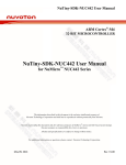
Connect the motor as indicated below, motor phases (3 thick wires on pin 1,2 & 3) and
Hall sensors (5 thin wires on pin 4 to 8) .
Figure 2-1 . Motor Connection on Evaluation Board
Pin 1
3 Thick wires from motor phases
5 Thin wires from Hall sensors
Table 2-1 . J5 Pin Numbers vs Motor Wires
ATAVRMC100 User Manual
Pin number
Motor Wire
Remark
Signals names on
Schematics
1
Yellow
Thick wire
PH_A
2
Red
Thick wire
PH_B
3
Black
Thick wire
PH_C
4
Red
Thin Wire
VCC5V
5
Blue
Thin Wire
HALL_A
6
Green
Thin Wire
HALL_B
7
White
Thin Wire
HALL_C
8
Black
Thin Wire
GND
5
7551B–AVR–02/06
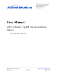
Connect the ATAVRMC100 to an external 9 DC - 16V DC power supply as indicated
below. The power supply must be able to deliver up to 4 amps of power.
Figure 2-2 . Supply Connection on ATAVRMC100 Development Board
J1 Power Connector
Pin 1
Power Supply (12V -16 VDC- 4A)
Ground
Table 2-2 . J1 Pin number vs Supply Connection
Pin number
Signal
Remark
1
Positive Input
12V to 16 VDC
2
NC
3
Ground
The green D6 LED is lit when power is on. At power up, it runs the demonstration program stored in the AT90PWM3. It makes the motor run in hall sensor mode.
The Hall sensor jumpers must be set as below on the ATAVRMC100.
Figure 2-3 . Default Hall sensor jumper configuration
ATAVRMC100 User Manual
6
7551B–AVR–02/06
Section 3
Hardware Description
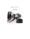
3.1
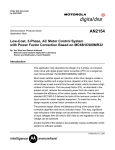
Block Diagram
Figure 3-1. ATAVRMC100 Block Diagram
IO for users Lin network
Power
Supply
12V to 16V DC
IO
LIN
NMOS FETs
(3 Half Bridges)
x3
Supply Measurement
NMOS FET
drivers
Isp (Avr Studio)
ISP
Connector
BLDC
Motor
Zero
Crossing Detection
AT90PWM3
Low Level Tests
Test points
Current Measurement
&
Over Current
Detection
Hall sensor
connector
3.2
Power Supply
3.2.1
Power Supply
The power supply source must be beetween 12V DC to 16V DC with 4 amps. See Getting Started chapter for power ATAVRMC100 power supply connection
Note:
ATAVRMC100 User Manual
WARNING : There is no protection against inverting power supply polarity.
The “VCC-ON“ D6 LED is always lit when power is applied to ATAVRMC100 .
7
7551B –AVR–02/06
Figure 3-2 . “VCC-ON” D6 LED Position
D6 - Led
3.3
ISP Connector
ATAVRMC100 has a six pin ISP connector (J2) allowing to reprogram the part with new
code using standard AVR ISP tools
Figure 3-3 . J2 - ISP Connector Position
ISP Connector
ATAVRMC100 User Manual
8
7551B–AVR–02/06
Pins number
Signals
1
MISO
2
VCC 5V
3
SCK
4
MOSI
5
/ Reset
6
Ground
For details informations about programming tools using ISP connector, refer to programming chapter.
3.4
EXT DRV Connector
J3 connector is available to connect standart AVR product to power interface of
ATAVRMC100. The following signals are connected to J3.
Pins number
Notes:
ATAVRMC100 User Manual
Signal
1
H_A
2
L_A
3
H_B
4
L_B
5
H_C
6
L_C
7
V shunt +
8
V shunt -
9
VMOT Half
10
Overcurrent
1. AT90PWM3 part should be erased to avoid conflict when using any external AVR
product.
2. PSC0RB, PSC1RB and PSC2RB fuse bits must be unprogrammed (=1) to avoid I/O
conflict.
9
7551B–AVR–02/06
3.5
IO Connector
J4 connector is available for ATAVRMC100 users.
The following signals are connected to J4.
Pins number
Signal
1
PB3 / AMP0M
2
PB4 / AMP0P
3
PC1 / OC1B / PSCIN1
4
PC2 / TO / PSCOUT22
5
PB5 / ADC6 / INT2
6
PE1 / OCB0 / XTAL1
7
PD3 / LIN TXD-RXD / TXD DALI / OCO / SS / MISO
8
PD4 / ADC1 / RXD DALI / ICP1A / SCK
9
GROUND
10
5V VCC
Figure 3-4 . J4 IO Connector Position
J4 IO Connector
ATAVRMC100 User Manual
10
7551B–AVR–02/06
3.6
LIN network
AT90PWM3 may support a software LIN implementation. The ATAVRMC100 implemesnt an Atmel LIN transceiver (ATA6661). A 3-pin connector assumes the LIN bus
connections. This connector is also the power supply connector.
Figure 3-5 . LIN 3-pin Connector
J1 Power Connector
Pin 1
Power Supply (12V-16 VDC- 4A)
Lin Network
Ground
3.7
Pin number
Signal
Remark
1
Positive Input
12V to 16 VDC
2
LIN Network
3
Ground
Hall sensor
The ATAVRMC100 board allows to control motors with or without Hall sensors.
When using Hall sensors, jumpers must be connected as below.
Figure 3-6 . Hall Sensors Jumper Configuration
ATAVRMC100 User Manual
11
7551B–AVR–02/06
In sensorless mode jumpers have to be set as shown below
Figure 3-7 . Sensorless Mode Jumper Configuration
ATAVRMC100 User Manual
12
7551B–AVR–02/06
3.8
Test Points
ATAVRMC100 board has test points for debug and engineering development.
The following table summarises all test points, please refer to schematics for detailed
informations.
Test Point Number
ATAVRMC100 User Manual
Signal Name
Schematic page Number
TP1
PH_C
Page 2/4
TP2
Hall_C
Page 2/4
TP3
Hall_B
Page 2/4
TP4
Hall_A
Page 2/4
TP5
PH_B
Page 2/4
TP6
V_Shunt +
Page 2/4
TP7
V_Shunt +
Page 2/4
TP8
Over_current
Page 2/4
TP9
PH_A
Page 2/4
TP10
Ground
Page 3/4
TP11
BEMF_C
Page 4/4
TP12
BEMF_B
Page 4/4
TP13
BEMF_A
Page 4/4
TP14
Current_Detection
Page 2/4
13
7551B–AVR–02/06
Figure 3-8 . ATAVRMC100 Test Points Position
ATAVRMC100 User Manual
14
7551B–AVR–02/06
Section 4
Programming ATAVRMC100
4.1
In-System Programming
The AT90PWM3 can be programmed using specific SPI serial links. This section
explains how to connect the programmer.
The Flash, EEPROM memory (and all Fuse and Lock Bit options ISP-programmable)
can be programmed individually or with the sequential automatic programming option.
WARNING: If debugWire fuse is enabled, AVR ISP can’t be used. If debugWire
fuse is disabled, JTAGICE mkII have to be used in ISP mode to enabled debugWire fuse.
4.1.1
Programming with AVR ISP Programmer
The AVR ISP programmer is a compact and easy-to-use In-System Programming tool
for developing applications with AT90PWM3. Due to the small size, it is also an excellent tool for field upgrades of existing applications. It is powered by the ATAVRMC100
and an additional power supply is thus not required.
The AVR ISP programming interface is integrated in AVR Studio.
To program the device using AVR ISP programmer, connect the 6-wire cable on the ISP
connector of the ATAVRMC100 as shown in Figure 4-1.
Note:
ATAVRMC100 User Manual
See AVR Studio on-line Help for information.
15
7551B –AVR–02/06
Figure 4-1 . Programming from AVR ISP programmer
MISO
SCK
RESET
1 2
3 4
5 6
VCC
MOSI
GND
ISP CON
4.1.2
Programming with STK500
The AT90PWM3 can be programmed using the serial programming mode in the AVR
Studio STK500 software. The software interface (In-System Programming of an external
target system) is integrated in AVR Studio.
To program the device using ISP from STK500, connect the 6-wire cable between the
ISP6PIN connector of the STK500 board and the ISP connector of the ATAVRMC100
as shown in Figure 4-2.
Note:
ATAVRMC100 User Manual
See AVR Studio on-line Help for information.
16
7551B–AVR–02/06
Figure 4-2 . Programming from STK500
The Flash, EEPROM memory (and all Fuse and Lock Bit options ISP-programmable)
can be programmed individually or with the sequential automatic programming option.
4.1.3
Programming using JTAGICE mkII
The AT90PWM3 can also be programmed using the JTAGICE mkII emulator in debug
Wire mode. In this mode, AT90PWM3 starts running code only when JTAGICE is disconnected. All software is available in AVR Studio.
ATAVRMC100 User Manual
17
7551B–AVR–02/06
Figure 4-3 . Programming from JTAGICE mkII
4.2
Debugging
AT90PWM3 has embedded On-chip debugWire that allows emulation with
ATAVRMC1OO using JTAGICE mkII only.
WARNING: If debugWire fuse is enabled, AVR ISP can’t be used. If debugWire
fuse is disabled, JTAGICE MKII have to be used in ISP mode to enabled debugWire fuse.
ATAVRMC100 User Manual
18
7551B–AVR–02/06
Section 5
Basic Test Program
The program below is the example of the main routine loaded into
AT90PWM3 on the ATAVRMC100 kit, it allow motor to turn at low speed.
/*********************************************************************
* @file main.c
*
* Copyright (c) 2005 Atmel.
*
* @brief This module provide services to show a simple program for
* AT90PWM3 Only
* @version 1.0 (CVS revision : $Revision: 1.15 $)
* @date $Date: 2005/06/30 09:17:19 $
* @author $Author: gallain $
**********************************************************************/
#include "config.h"
#include
#include
#include
#include
"mc_lib.h"
"mc_control.h"
"mc_drv.h"
"serial.h"
#include "adc\adc_drv.h"
#include <stdio.h>
#include "mc_test_procedure.h"
U16 g_regulation_period = 0;
U16 motor_speed = 0;
extern Bool g_tic;
//!< Define the sampling period
//!< User Speed Order
//see mc_drv.c Use for sampling time
//! Main user routine.
//! The main user routine provides an UART control for the motor.
//! The mc_regulation_loop() function is launched every 80ms.
//! '0,1,2,3' are used to set the speed of the motor.
//! '&,é,",(' are used to select the regulation loop (Open loop, speed,
//!current, position).
//! Press 'r' key to start the motor.
//! Press 's' key to stop the motor.
//! Press 'f' and 'b' keys to choose between CW and CCW rotation
//!direction.
//! Press 'v' key to print all motor parameters.
//! Press 'i' key to initialize the motor after Over current detection.
//! Press '-' and '+' keys to decrease or increase motor speed value.
void main(void)
{
// init motor
ATAVRMC100 User Manual
19
7551B –AVR–02/06
mc_motor_init();
// launch initialization of the motor
// init UART
init_uart();
// If PB5 == 1 : Launch the test function.(Only use for Board test)
if(Get_EXT3() == 0)mc_Board_test();
// UART print screen - uncomment for UART use
/*putstring("\033[2J"); // CLS, VT100 ANSI sequence
putstring("ATMEL BLDC Motor Control.");
putstring("\n\r");
sendchar(':');*/
// Start the motor
mc_set_motor_speed(50);
mc_motor_run();
while(1)
{
// UART IHM
// The code below provide an UART control for the motor
// uncomment for UART use
/*if(tstrx()==TRUE)
{
char answ = '\0';
answ = recchar();
sendchar(answ);
putstring("\n\r\0");
switch(answ)
{
case 'r' : // launch the motor
putstring("Run\n\r\0");
mc_set_motor_speed(motor_speed);
mc_reset_Num_Turn();
mc_motor_run();
break;
case 's' : // stop the motor
putstring("Stop\n\r\0");
mc_motor_stop();
break;
case 'f' : // Select forward direction
putstring("CW\n\r\0");
mc_motor_stop();
mc_set_motor_direction(CW);
mc_motor_run();
break;
case 'b' : // Select backward direction
putstring("CCW\n\r\0");
mc_motor_stop();
mc_set_motor_direction(CCW);
mc_motor_run();
break;
case 'v' : // print motor information
putstring("Cmd :");
putint(mc_get_motor_speed());
putstring("\n\r");
putstring("Speed:");
putint(mc_get_motor_measured_speed());
putstring("\n\r");
putstring("Current:");
putint(mc_get_measured_current());
putstring("\n\r");
putstring("Turns:");
ATAVRMC100 User Manual
20
7551B–AVR–02/06
putint(mc_get_Num_Turn());
putstring("\n\r");
break;
case '0' : // No regulation (Open Loop)
motor_speed = 50;
break;
case '1' : // Set speed regulation
motor_speed = 100;
break;
case '2' : // Set current regulation
motor_speed = 150;
break;
case '3' : // Set position regulation
motor_speed = 255;
break;
case '&' : // No regulation (Open Loop)
mc_set_Open_Loop();
break;
case 'é' : // Set speed regulation
mc_set_Speed_Loop();
break;
case '"' : // Set current regulation
mc_set_Current_Loop();
break;
case '(' : // Set position regulation
mc_reset_Num_Turn();
mc_set_Position_Loop();
break;
case '+' : // Set current regulation
motor_speed ++;
break;
case '-' : // Set position regulation
motor_speed --;
break;
case 'i' : // Init PSC, Restart PSC after Over_Current detection
PSC0_Init(255,0,1,0);
PSC1_Init(255,0,1,0);
PSC2_Init(255,0,1,0);
break;
default :
putstring("Unknown command\n\r\0"); // Unknow Command
try again
}
sendchar(':');
}*/
// Show PSC state according to the Over Current information
if(PCTL2 & (1<<PRUN2)) switch_OFF_LED();// PSC ON
else switch_ON_LED();//PSC OFF => Over_Current
// Launch regulation loop
// Timer 1 generate an IT (g_tic) all 250us
// Sampling period = n * 250us
if (g_tic == TRUE)
{
g_tic = FALSE;
// Get Current and potentiometer value
mc_ADC_Scheduler();
g_regulation_period += 1;
if ( g_regulation_period >= 320 ) //n * 250us = Te
{
g_regulation_period = 0;
//mc_set_motor_speed(motor_speed); // Set User Speed Command for
an UART control
ATAVRMC100 User Manual
21
7551B–AVR–02/06
mc_set_motor_speed(mc_get_potentiometer_value()); // Set User
Speed Command with potentiometer
mc_regulation_loop(); // launch regulation loop
}
}
}
}
ATAVRMC100 User Manual
22
7551B–AVR–02/06
Section 6
Troubleshooting Guide
Table 6-1 . Troubleshooting Guide
Problem Description
ATAVRMC100 User Manual
Reason
Solution
ATAVRMC100 does not work
and D6 led is off
No power supply
Check the power supply
source
BLDC Motor does not turn
Hall sensor disabled
Check Hall sensor jumper
configuration
BLDC Motor turns slowly or
does not turn
Current of the supply is not
enought important
Check current of your supply
4A is the correct value
BLDC Motor starts and stop
immediatly at power up with
D1 led ON
In rush currrent is to high
regarding overcurrent
detection
limit the current of the supply
to bypass inrush current
23
7551B –AVR–02/06
Section 7
Technical Specifications
System Unit
– Physical Dimensions (Board only) ..............................L=75 x W=55 x H=15 mm
– Weight (Board only) ......................................................................................29 g
Operating Conditions
– Voltage Supply ......................................................................12V to 16VDC (4A)
– Operating Temperature range ................................................. From 0°C to 70°C
Motor unit
– Physical Dimensions ...............................................L=63.1 x W=42 x H=42 mm
– Weight ........................................................................................................250 g
ATAVRMC100 User Manual
24
7551B –AVR–02/06
Section 8
Technical Support
For Technical support, please contact [email protected]. When requesting technical support, please include the following information:
Version number of AVR Studio. This can be found in the AVR Studio help menu.
Hardware revision of ATAVRMC100 board (found on PCB).
PC operating system and version/build
PC processor type and speed
A detailed description of the problem
ATAVRMC100 User Manual
25
7551B –AVR–02/06
Section 9
Complete Schematics
On the next pages, the following documents of ATAVRMC100 revision ATAVRMC100B
are shown:
Complete schematics
Assembly drawing
Silkscreen
Bill of materials
ATAVRMC100 User Manual
26
7551B –AVR–02/06
ATAVRMC100 User Manual
A
B
C
D
D1
7
EXT3
C1
EXT6
L_C
H_C
5
EXT7/MOSI/LIN_TxD/TxD
EXT1
EXT3
EXT4
EXT1
EXT3
EXT5
EXT7/MOSI/LIN_TxD/TxD
MISO/EXT10
EXT8/SCK/LIN_RxD/RxD/POT
NRES/EXT9
R3
100K
1
3
5
7
9
EXT2
EXT4
EXT6
EXT8
VCC
PORT_COM
CON 2x5
EXT1
EXT3
EXT5
EXT7
GND
J4
4
VCC
MOSI
GND
JTAG ISP
MISO
SCK
RST
J2
2
4
6
AT90PWM3
PD7/ACMP0
PB2/ADC5/INT1
PC4/ADC8/AMP1M
PC5/ADC9/AMP1P
AVCC
AGND
AREF
PC6/ADC10/ACMP1
PB3/AMP0M
PB4/AMP0P
PC7/D2A
PB5/ADC6/INT2
32
17
18
19
20
21
22
23
24
25
26
27
28
29
30
31
3
1
3
5
7
9
L_A
L_B
L_C
VOCur
STK500_CON
J3
1uF
100nF
EXT1
EXT2
2
4
6
8
10
DAC_OUT
EXT5
L_B
L_A
BEMF_B
HallB
1
2
3
JP2
BEMF_A
HallA
1
2
3
JP1
L_A
L_B
L_C
V_ShuntOver_Current
L_A
L_B
L_C
V_ShuntOver_Current
Sel_Sensor_Sensorless_C
Sel_Sensor_Sensorless_A
JP3
HallC
1
HallC
2
BEMF_C
3
BEMF_C
BEMF_A
HallA
Sel_Sensor_Sensorless_B
BEMF_B
HallB
1
2
Date: 5 sept 2005
A4
Document Number
Sheet
1
1
of
4
Rev
1.7
ATAVRMC100 (MicroController)
Size
EXT2
EXT4
Title
EXT6
EXT8/SCK/LIN_RxD/RxD/POT
H_A
H_B
H_C
V_Shunt+
VMOT_Half
C4
H_A
H_B
H_C
V+
Vmot
VMOT_Half
VMOT
V_Shunt-
C3
100nF
C2
V_Shunt+
R1
10
VCC5V
2
EXT7/MOSI/LIN_TxD/TxD
VMOT_Half
VMOT
V_Shunt-
V_Shunt+
AGND
EXT1
EXT2
DAC_OUT
EXT5
L_B
L_A
H_A
H_B
H_C
V_Shunt+
VMOT_Half
EXT7/MOSI/LIN_TxD/TxD
VCC5V
PD5/ADC2/ACMP2
PD6/ADC3/ACMPM/INT0
EXT2
EXT2
EXT6
EXT8/SCK/LIN_RxD/RxD/POT
VCC5V
2
4
6
8
10
1
3
5
PB7/ADC4/PSCOUT01/SCK
3
PB6/ADC7/PSCOUT11/ICP1B
PD4/ADC1/RXD/DALI/ICP1A/SCK_A
PE2/ADC0/XTAL2
PE1/OCB0/XTAL1
PB1/MOSI/PSCOUT21
PB0/MISO/PSCOUT20
PC3/T1/PSCOUT23
PC2/T0/PSCOUT22
GND
VCC
PC1/PSCIN1/OC1B
PD3/TXD/DALI/OC0/SS/MISO_A
PD2/PSCIN2/OC1A/MISO_A
PD1/PSCIN0/CLKO
PE0/RESET/OCD
PC0/INT3/PSCOUT10
PD0/PSCOUT00/XCK/SS_A
U1
4
MISO/EXT10
EXT8/SCK/LIN_RxD/RxD/POT
NRES/EXT9
VCC5V
16
15
14
13
12
11
LIN_NSLP
9
10
EXT4
R47 1K
6
EXT7/MOSI/LIN_TxD/TxD
100nF
5
MISO/EXT10
8
4
EXT8/SCK/LIN_RxD/RxD/POT
EXT6
L_C
H_C
LIN_NSLP
EXT4
EXT3
3
2
1
Over_Current
R46 1K
R45 1K
NRES/EXT9
H_B
H_A
EXT8/SCK/LIN_RxD/RxD/POT
LED_Green
R2
4.7K
VCC5V
10
VCC5V R48
EXT7/MOSI/LIN_TxD/TxD
MISO/EXT10
Over_Current
NRES/EXT9
H_B
H_A
5
A
B
C
D
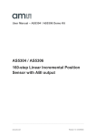
Figure 9-1 . Schematics, 1 of 4
27
7551B–AVR–02/06
A
B
C
H_A
L_A
H_B
L_B
H_C
L_C
H_A
L_A
H_B
L_B
H_C
L_C
5
R22
10K
10K
10K
10K
R21
R14
10K
10K
R16
R9
R4
4
2
3
4
2
3
4
2
3
IR2101S
HO
VS
COM LO
HIN VCC
LIN
VB
U4
IR2101S
HO
VS
COM LO
HIN VCC
LIN
VB
U3
IR2101S
HO
VS
COM LO
HIN VCC
LIN
VB
U2
100nF
C7
100nF
C12
7
6
5
1
8
100nF
C17
100nF
VIR2101
C14
7
6
5
1
8
100nF
C8
VIR2101
7
6
5
1
8
100nF
4
TP1
TP5
TP9
22
R24
22
R23
D4
BAS21
22
R19
22
R15
D3
BAS21
22
R10
22
R5
D2
BAS21
PH_A
PH_B
PH_C
VBUS
3
Q6
SUD35N05-26L
PH_A
Q5
SUD35N05-26L
Q4
SUD35N05-26L
PH_B
Q3
SUD35N05-26L
Q2
SUD35N05-26L
PH_C
Q1
SUD35N05-26L
VCC5V
10nF
R20 15K
4
3
TP7
TP6
PH_C
PH_B
PH_A
100
100
100
U5
Over_Cur
Over_Current
LMV7219M5
1
100nF
PH_C
PH_B
PH_A
HS_C
HS_B
HS_A
TP8
V_ShuntV_Shunt-
C13
1nF
V_Shunt+
V_Shunt+
VCC5V C15
Cur_Dtc
TP14
R18
R_Shunt
R17 4.7K
R13
R12
R11
8
7
6
5
4
3
2
1
BLDC Con
J5
Over_Current
V_Shunt-
V_Shunt+
100nF
C6
VCC5V
1
Document Number
2
Sheet
2
1
of
4
Rev
1.7
ATAVRMC100 (POWER BRIDGE)
C16
HallC
HallB
HallA
Date: 5 sept 2005
A4
Size
Title
DAC_OUT
HallC
HallB
HallA
TP2 TP3 TP4
HallB
C5
HallC
D
D7
HallA
SMBJ18
4.7K
R6
VIR2101
2
C10 1nF
C9 1nF
3
4.7K
R7
10
4
4.7K
R8
C11 1nF
VIR2101
5
2
R49
5
-
ATAVRMC100 User Manual
+
VBUS_D
A
B
C
D
Figure 9-2 . Schematics, 2 of 4
28
7551B–AVR–02/06
ATAVRMC100 User Manual
A
B
C
D
VMOT_Half
C24
2.2nF
VMOT
5
V measurement
R32
22K
R31
22K
R28
100K
R27
15K
VBUS_D
5
LL4001
D5
C27
100nF
VMOT_Half
VMOT
POWER
VBUS
R25 10
C19
47uF
4
LIN
EXT7/MOSI/LIN_TxD/TxD
LIN_NWAKE
LIN_NSLP
EXT8/SCK/LIN_RxD/RxD/POT
100nF
C18
VBUS_D
VOUT
4
EXT7/MOSI/LIN_TxD/TxD
3
3
LIN_NWAKE
2
LIN_NSLP
10K
R29
10nF
C21
5
6
7
8
C22
C23
10uF
C25
100nF
R30
33
VBUS_D
100nF
C26
220pF
LIN
VBUS
J1
GND
TP10
VCC5V
LIN Connector
1
2
3
1
Document Number
2
Sheet
3
1
of
4
ATAVRMC100 (POWER + LIN)
GND
LIN
BAT
INH
D6
LED_Green
R26
4.7K
2
Date: 5 sept 2005
A4
Size
Title
ATA6661
TxD
NWAKE
NSLP
RxD
U7
2
MC78M05CDT
VBUS_D
VIN
U6
1
1
EXT8/SCK/LIN_RxD/RxD/POT
100nF
C20
3
GND
3
4
Rev
1.7
A
B
C
D
Figure 9-3 . Schematics, 3 of 4
29
7551B–AVR–02/06
ATAVRMC100 User Manual
A
B
C
D
5
5
PH_A
PH_B
PH_C
PH_A
PH_B
PH_C
4
15K
R42
15K
R37
15K
R33
4
100K
R43
BEMF_A
100K
R38
BEMF_B
100K
R34
BEMF_C
R44
22K
R41
22K
BEMF_A
TP13
R40
22K
R39
22K
BEMF_B
TP12
R36
22K
R35
22K
BEMF_C
TP11
100pF
C32
BEMF_A
100pF
C30
3
470pF (Not Mounted)
C33
470pF (Not Mounted)
C31
470pf (Not Mounted)
100pF
BEMF_B
C29
C28
BEMF_C
3
1
Document Number
2
Sheet
4
1
of
4
Rev
1.7
ATAVRMC100 (ZCD Detection)
Date: 5 sept 2005
A4
Size
Title
2
A
B
C
D
Figure 9-4 . Schematics, 4 of 4 ATAVR MC100
30
7551B–AVR–02/06
Figure 9-5 . Assembly drawings component side
Figure 9-6 . Assembly drawings solder side
ATAVRMC100 User Manual
31
7551B–AVR–02/06
Figure 9-7 . Silk Screen Component Side 1
Figure 9-8 . Silkscreen Component Side 2
ATAVRMC100 User Manual
32
7551B–AVR–02/06
9.1
Bill of Materials
Reference
Part
Part Description
Package
C1,C2,C3,C5,
100nF
50V-5% Ceramic Capacitor
CASE 0805
C4
1uF
16V -20/+80%
CASE 0805
C9,C10,C11,C13
1nF
50V-5% Ceramic Capacitor
CASE 0805
C16,C21
10nF
50V-5% Ceramic Capacitor
CASE 0805
C19
47uF
25V
C23
10uF
6,3V
C24
2.2nF
50V-5% Ceramic Capacitor
CASE 0805
C26
220pF
50V-5% Ceramic Capacitor
CASE 0805
C28,C30,C32
100pF
50V-5% Ceramic Capacitor
CASE 0805
C29,C31,C33
470pF (Not Mounted)
50V-5% Ceramic Capacitor
D1,D6
LED_Green
TOPLED LP M670
PLCC-2
BAV21
Rectifier Diode 0,1mA
SOT23
D5
LL4001
Rectifier Diode MELF 1A
RMELF
JP1
Sel_Sensor_Sensorless
_A
Right male bars Step2,54 * 3
JP2
Sel_Sensor_Sensorless
_B
Right male bars Step2,54 * 3
JP3
Sel_Sensor_Sensorless
_C
Right male bars Step2,54 * 3
J1
LIN Connector
Connector block Step3,81 3 Pins
J2
CON 2x3
Right male bars Step2,54 * 3 *2
J3,J4
CON 2x5
Male connector with "detrompeur" 2X5
J5
BLDC Con
Connector block Step3,81 8 Pins
C6,C7,C8,C12,
C14,C15,C17,C18,
C20,C22,C25,C27
ATAVRMC100 User Manual
.
33
7551B–AVR–02/06
Reference
Part
Part Description
Package
Q1,Q2,Q3,Q4,Q5,Q6
SUD35N05-26L
Power MOSFET CMS
TO-252 (D-pak)
R1,R25, R48
10
1/16W-5% Resistor SMD
CASE 0805
R2,R6,R7,R8,R17,R26
4.7K
1/16W-5% Resistor SMD
CASE 0805
R3,R28,R34,R38,R43
100K
1/16W-5% Resistor SMD
CASE 0805
R4,R9,R14,R16,R21,R22,
10K
1/16W-5% Resistor SMD
CASE 0805
R5,R10,R15,R19,R23,R2
4
22
1/16W-5% Resistor SMD
CASE 0805
R11,R12,R13
100
1/16W-5% Resistor SMD
CASE 0805
R18
R_Shunt
CMS POWER resistor 0,1ohm 3W
CASE 2512
R20,R27,R33,R37,R42
15K
1/16W-5% Resistor SMD
CASE 0805
R30
33
1/16W-5% Resistor SMD
CASE 0805
R31,R32,R35,R36,R39,R
40,
22K
1/16W-5% Resistor SMD
CASE 0805
T_POINT
Test Point Step2,54
U1
AT90PWM3
ATMEL Microcontroller
SO32
U2,U3,U4
IR2101S
Power Drivers MOSFET/IGBT
SOIC8
U5
LMV7219M5
Comparator 7ns rail to rail
SOT23-5
U6
MC78M05CDT
Regulator SMD Positif FIX 5V
SMD DPAK
U7
ATA6661
LIN Transceiver
R-SO8
R45, R46, R47
1K
1/16W-5% Resistor SMD
CASE 0805
D7
SMBJ18
R49
10
R29
R41,R44
TP1,TP2,TP3,TP4,TP5,T
P6,
TP7,TP8,TP9,TP10,TP11
TP12,TP13,TP14
ATAVRMC100 User Manual
CASE 1206
34
7551B–AVR–02/06
Atmel Corporation
2325 Orchard Parkway
San Jose, CA 95131
Tel: 1(408) 441-0311
Fax: 1(408) 487-2600
Regional Headquarters
Europe
Atmel Sarl
Route des Arsenaux 41
Case Postale 80
CH-1705 Fribourg
Switzerland
Tel: (41) 26-426-5555
Fax: (41) 26-426-5500
Asia
Room 1219
Chinachem Golden Plaza
77 Mody Road Tsimshatsui
East Kowloon
Hong Kong
Tel: (852) 2721-9778
Fax: (852) 2722-1369
Japan
9F, Tonetsu Shinkawa Bldg.
1-24-8 Shinkawa
Chuo-ku, Tokyo 104-0033
Japan
Tel: (81) 3-3523-3551
Fax: (81) 3-3523-7581
Atmel Operations
Memory
2325 Orchard Parkway
San Jose, CA 95131
Tel: 1(408) 441-0311
Fax: 1(408) 436-4314
RF/Automotive
Theresienstrasse 2
Postfach 3535
74025 Heilbronn, Germany
Tel: (49) 71-31-67-0
Fax: (49) 71-31-67-2340
Microcontrollers
2325 Orchard Parkway
San Jose, CA 95131
Tel: 1(408) 441-0311
Fax: 1(408) 436-4314
La Chantrerie
BP 70602
44306 Nantes Cedex 3, France
Tel: (33) 2-40-18-18-18
Fax: (33) 2-40-18-19-60
ASIC/ASSP/Smart Cards
1150 East Cheyenne Mtn. Blvd.
Colorado Springs, CO 80906
Tel: 1(719) 576-3300
Fax: 1(719) 540-1759
Biometrics/Imaging/Hi-Rel MPU/
High Speed Converters/RF Datacom
Avenue de Rochepleine
BP 123
38521 Saint-Egreve Cedex, France
Tel: (33) 4-76-58-30-00
Fax: (33) 4-76-58-34-80
Zone Industrielle
13106 Rousset Cedex, France
Tel: (33) 4-42-53-60-00
Fax: (33) 4-42-53-60-01
1150 East Cheyenne Mtn. Blvd.
Colorado Springs, CO 80906
Tel: 1(719) 576-3300
Fax: 1(719) 540-1759
Scottish Enterprise Technology Park
Maxwell Building
East Kilbride G75 0QR, Scotland
Tel: (44) 1355-803-000
Fax: (44) 1355-242-743
e-mail
[email protected]
Web Site
http://www.atmel.com
Disclaimer: The information in this document is provided in connection with Atmel products. No license, express or implied, by estoppel or otherwise,to anyintellectualproperty right is granted by this document or in connection with the sale of Atmel products. EXCEPT AS SET FORTH IN ATMEL’S TERMS AND CONDI-TIONS OF
SALE LOCATED ON ATMEL’S WEB SITE, ATMEL ASSUMES NO LIABILITY WHATSOEVER AND DISCLAIMS ANY EXPRESS, IMPLIED OR STATUTORYWARRANTY RELATING TO ITS PRODUCTS INCLUDING, BUT NOT LIMITED TO, THE IMPLIED WARRANTY OF MERCHANTABILITY, FITNESS FOR A PARTICULARPURPOSE, OR NON-INFRINGEMENT. IN NO EVENT SHALL ATMEL BE LIABLE FOR ANY DIRECT, INDIRECT, CONSEQUENTIAL, PUNITIVE, SPECIAL
OR INCIDEN-TAL DAMAGES (INCLUDING, WITHOUT LIMITATION, DAMAGES FOR LOSS OF PROFITS, BUSINESS INTERRUPTION, OR LOSS OF INFORMATION) ARISING OUTOF THE USE OR INABILITY TO USE THIS DOCUMENT, EVEN IF ATMEL HAS BEEN ADVISED OF THE POSSIBILITY OF SUCH DAMAGES. Atmel makes norepresentationsor warranties with respect to the accuracy or completeness of the contents of this document and reserves the right to make
changes to specificationsand product descriptions at any time without notice. Atmel does not make any commitment to update the information contained herein.
Unless specifically provided otherwise, Atmel products are not suitable for, and shall not be used in, automotive applications. Atmel’s products are not intended,
authorized, or warranted for useas components in applications intended to support or sustainlife.
© Atmel Corporation 2006. All rights reserved. Atmel®, logo and combinations thereof, are registered trademarks, and Everywhere You Are SM
are the trademarks of Atmel Corporation or its subsidiaries. Other terms and product names may be trademarks of others.
7551B –AVR–02/06
/xM