1
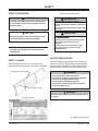
WESTERN PRODUCTS, P.O. BOX 245038, MILWAUKEE, WI 53224-9538
Lit. No. 63617
September 13, 2002
DODGE DAKOTA and DURANGO
2000 & LATER
INSTALLATION INSTRUCTIONS
Model No. 3915
Mount Assembly Box No. 63620
Hydraulics Box No. 56365
Headlamp Kits Selection
2001 Model Year and Later
Without DRL’s Harness Kit No. 61185, 63412
Headlamp Kit No. 61540-1
With DRL’s Harness Kit No. 61185, 63412, 61584
Headlamp Kit No. 61540-1
2000 Model Year
Without DRL’s Harness Kit No. 63396, 61185
Headlamp Kit No. 61540-1
With DRL’s Harness Kit No. 61185, 63404, 61584
Headlamp Kit No. 61550-1
CAUTION
Read this document before installing the snowplow.
CAUTION
See your WESTERN outlet for application
recommendations. The Selection List has specific
vehicle and snowplow requirements.
®
A DIVISION OF DOUGLAS DYNAMICS, L.L.C.
TABLE OF CONTENTS
SAFETY . . . . . . . . . . . . . . . . . . . . . . . . . . . . . . . . . . . 1
Safety Definitions . . . . . . . . . . . . . . . . . . . . . . . . . 1
Safety Labels . . . . . . . . . . . . . . . . . . . . . . . . . . . . 1
Safety Precautions . . . . . . . . . . . . . . . . . . . . . . . 1
Personal Safety . . . . . . . . . . . . . . . . . . . . . . . . . . 2
Fire and Explosion . . . . . . . . . . . . . . . . . . . . . . . . 2
Ventilation . . . . . . . . . . . . . . . . . . . . . . . . . . . . . . 2
Battery Safety . . . . . . . . . . . . . . . . . . . . . . . . . . . 3
Hydraulic Safety . . . . . . . . . . . . . . . . . . . . . . . . . 3
Torque Chart . . . . . . . . . . . . . . . . . . . . . . . . . . . . 3
MOUNT INSTALLATION . . . . . . . . . . . . . . . . . . . . . . 4
Fog Lamps . . . . . . . . . . . . . . . . . . . . . . . . . . . . . 4
Mount Frame . . . . . . . . . . . . . . . . . . . . . . . . . . . . 4
Thrust Arms . . . . . . . . . . . . . . . . . . . . . . . . . . . . . 5
Link Arms . . . . . . . . . . . . . . . . . . . . . . . . . . . . . . 5
Bumper . . . . . . . . . . . . . . . . . . . . . . . . . . . . . . . . 5
Harness Kit Selection . . . . . . . . . . . . . . . . . . . . . 5
SOLENOID CONTROL INSTALLATION . . . . . . . . . . 6
Solenoid Control - Floor Mounted Installation
Instructions . . . . . . . . . . . . . . . . . . . . . . . . . . . . 6
Lit. No. 63617
UNDERHOOD INSTALLATION . . . . . . . . . . . . . . . . . 7
Vehicle Harness and Motor Relay . . . . . . . . . . . . 7
PLUG-IN HARNESS AND HEADLAMP RELAY
INSTALLATION . . . . . . . . . . . . . . . . . . . . . . . . . 10
Plug-In Harness and Headlamp Installation . . . . 10
OPERATIONAL TESTS AND ADJUSTMENTS . . . . 11
Filling Hydraulic Unit . . . . . . . . . . . . . . . . . . . . . 11
Blade Drop Speed Adjustment . . . . . . . . . . . . . . 12
Final Hydraulic Inspection . . . . . . . . . . . . . . . . . 12
Coupling Lug Height Check . . . . . . . . . . . . . . . . 12
Vehicle Lighting Check . . . . . . . . . . . . . . . . . . . 13
RELAY CONNECTIONS DIAGRAMS . . . . . . . . . . . . 14
2001 and Later Dakota with Dual HB-5
63412 Harness Kit – 9-Pin Headlamps . . . . . 14
2000 Dakota Dual HB-5
63396 Harness Kit – 9-Pin Headlmaps . . . . . 15
Dakota Dual HB-5 with DRL’s
63404 Harness Kit – 12-Pin Headlamps . . . . 16
ASSEMBLY DIAGRAM . . . . . . . . . . . . . . . . . . . . . . 17
September 13, 2002
SAFETY
SAFETY DEFINITIONS
Warning and Caution Label
WARNING
WARNING
Indicates a potentially hazardous situation that,
if not avoided, could result in death or serious
personal injury.
LOWER BLADE WHEN VEHICLE IS PARKED.
REMOVE BLADE ASSEMBLY BEFORE PLACING VEHICLE
ON HOIST.
DO NOT EXCEED GVWR OR GAWR INCLUDING BLADE
AND BALLAST.
CAUTION
CAUTION
Indicates a situation that, if not avoided, could
result in damage to product or property.
READ
SERVICING SNOWPLOW.
BEFORE OPERATING OR
TRANSPORT SPEED SHOULD NOT EXCEED 45 MPH.
REDUCE SPEED UNDER ADVERSE TRAVEL
CONDITIONS.
PLOWING SPEED SHOULD NOT EXCEED 10 MPH.
NOTE: Identifies tips, helpful hints and
maintenance information the owner/operator
should know.
SEE YOUR SALES OUTLET FOR APPLICATION
RECOMMENDATIONS.
59900
SAFETY PRECAUTIONS
SAFETY LABELS
Improper installation and operation could cause personal injury, and/or equipment and property damage.
Read and understand labels and the Owner’s Manual
before installing, operating, or making adjustments.
Become familiar with and inform users about the
warning and instruction labels on the back of the blade.
Warning and Caution Label
WARNING
Lower blade when vehicle is parked.
Temperature changes could change hydraulic
pressure, causing the blade to drop
unexpectedly or damaging hydraulic
components. Failure to do this can result in
serious personal injury.
Instruction Label
WARNING
Remove blade assembly before placing vehicle
on hoist.
Instruction Label
(Continued on next page.)
Lit. No. 63617
1
September 13, 2002
SAFETY
SAFETY PRECAUTIONS (CONTINUED)
PERSONAL SAFETY
• Wear only snug-fitting clothing while working on
WARNING
•
The driver shall keep bystanders clear of the
blade when it is being raised, lowered or angled.
Do not stand between the vehicle and the blade
or within 8 feet of a moving blade. A moving or
falling blade could cause personal injury.
•
•
•
your vehicle or snowplow.
Do not wear jewelry or a necktie, and secure long
hair.
Wear safety goggles to protect your eyes from
battery acid, gasoline, dirt and dust.
Avoid touching hot surfaces such as the engine,
radiator, hoses and exhaust pipes.
Always have a fire extinguisher rated BC handy, for
flammable liquids and electrical fires.
WARNING
Do not exceed GVWR or GAWR including blade
and ballast. The rating label is found on driverside vehicle door cornerpost.
FIRE AND EXPLOSION
WARNING
Gasoline is highly flammable and gasoline
vapor is explosive. Never smoke while working
on vehicle. Keep all open flames away from
gasoline tank and lines. Wipe up any spilled
gasoline immediately.
CAUTION
Refer to the current selection list for minimum
vehicle recommendations and ballast
requirements.
Be careful when using gasoline. Do not use gasoline to
clean parts. Store only in approved containers away
from sources of heat or flame.
CAUTION
To prevent accidental movement of the blade,
always turn the ON/OFF switch to OFF
whenever the snowplow is not in use. The
control indicator light will turn off.
VENTILATION
WARNING
Vehicle exhaust contains deadly carbon
monoxide (CO) gas. Breathing this gas, even in
low concentrations, could cause death. Never
operate a vehicle in an enclosed area without
venting exhaust to the outside.
Lit. No. 63617
2
September 13, 2002
SAFETY
TORQUE CHART
BATTERY SAFETY
CAUTION
CAUTION
Read instructions before assembling. Fasteners
should be finger tight until instructed to tighten
according to the torque chart. Use standard
methods and practices when attaching
snowplow including proper safety equipment.
Batteries normally produce explosive gases
which can cause personal injury. Therefore, do
not allow flames, sparks or lit tobacco to come
near the battery. When charging or working
near a battery, always cover your face and
protect your eyes, and also provide ventilation.
Batteries contain sulfuric acid which burns skin,
eyes and clothing.
Disconnect the battery before removing or
replacing any electrical components.
Recommended Fastener Torque
Chart (Ft.-Lb.)
CAUTION
Always disconnect the battery before removing
or replacing electrical components such as a
motor relay or battery cable.
Size
SAE
Grade 2
SAE
Grade 5
1/4-20
5/16-18
3/8-16
3/8-24
7/16-14
1/2-13
9/16-12
5/8-11
3/4-10
6
11
19
24
30
45
66
93
150
9
18
31
46
50
75
110
150
250
SAE
Grade 8
13
28
46
68
75
115
165
225
370
Metric Grade 8.8 (Ft.-Lb.)
HYDRAULIC SAFETY
Size
Torque
Size
M6
M8
M 10
7
17
35
M 12
M 14
M 16
Torque
60
95
155
These torque values apply to fasteners
except those noted in the instruction.
WARNING
Hydraulic oil under pressure could cause skin
injection injury. If you are injured by hydraulic
oil, get medical attention immediately.
• Always inspect hydraulic components and hoses
•
before using. Replace any damaged or worn parts
immediately.
If you suspect a hose leak, DO NOT use your
hand to locate it. Use a piece of cardboard or
wood.
Lit. No. 63617
3
September 13, 2002
MOUNT INSTALLATION
FOG LAMPS
3. Remove two bumper bracket nuts at front of frame
horns. Clamp bumper bracket to frame and use a
hammer and chisel under the head to drive out
M12 serrated button head screw. Remove clamp.
Repeat for other side. Retain parts for reinstallation
if mount is removed from vehicle.
1. Disconnect fog lamp harness from bumper lamps
if equipped.
MOUNT FRAME
4. Place mount frame onto vehicle frame horns. Align
slots in mount with slots in frame and holes in
bumper brackets. Fasten with 1/2"-13 x 1-1/2"
bolts, lock nuts, and washers. (Place nuts and
washers inside frame toward slots and outside of
vehicle.) Angle piece welded to side of spreader
must be against bottom of frame.
1. Open vehicle hood and remove four bumper bolts
from the top of bumper bracket. Remove two outer
bumper bracket bolts from side of frame. Remove
bumper with brackets. Cut off rubber portion of air
deflector attached to air dam and discard.
2. Remove snap fasteners and fan air deflector.
As Viewed From Driver Side
Typical Bumper
Bracket End View
Mount Frame
Lengthen Slot
1/4" to Inside
1/2" x 1-1/2" Bolt
Must be against
bottom of frame
1/2" x 1-1/4" Bolt
Chamfered side of
link arm holes
towards the center
of the vehicle
1/2" Dia. Drill
3/4" x 3-1/4"
Rivet
1/2" x 1-1/2"
U-Bolt
Link Arm
Link Arm
Lug
Thrust Frame
Notch
9-1/2" to 10-1/2"
Plow attached and
resting on ground
Coupling Lug
1/2" x 1-1/2" Bolt
Road
See Page 12
Lit. No. 63617
4
September 13, 2002
MOUNT INSTALLATION
THRUST ARMS
4. Reinstall fan air deflector behind radiator. It may be
necessary to cut away a portion from the right
angle area forward on the passenger side only.
1. Position driver side thrust arm to vehicle frame and
crossmember on driver side. Align hole in angle
with hole in mount frame. Fasten with 1/2" x 1-1/2"
bolt and lock nut. (Place lock nut toward outside of
vehicle.)
5. Reattach fog lamp wire harness plug if so
equipped.
2. Position thrust arm tightly into corner of vehicle
frame and crossmember. Clamp in place. Using
hole in thrust frame as a template, drill 1/2" hole
into both bottom of frame and lower hole in front
face of crossmember. Fasten with 1/2" x 1-1/4" bolt
with top flange lock nut on inside of frame and
U-bolt placed through top hole in crossmember.
Tighten all bolts to corresponding torque chart
values.
NOTE: During electrical installation, THE LONG
BATTERY GROUND CABLE (no stripe) MUST BE
GROUNDED TO THE NEGATIVE BATTERY
TERMINAL.
(Assembly tip: Tape lock nut to box end wrench
and assemble through front of frame. Use rubber
band provided to hold U-bolt in place when
attaching 1/2" locking nuts.)
HARNESS KIT SELECTION
3. Repeat steps 1 and 2 for passenger side.
LINK ARMS
All model years require the use of 61185 Park/Turn
Harness Kit in parklamp circuit. (Furnished in the Mount
Box.)
Assemble a link arm (chamfered side of holes towards
center of vehicle) between each pair of link arm lugs
with a 3/4" x 3-1/4" Grade 5 rivet and cotter pin.
DRL equiped vehicles require the installation of a 61584
DRL Kit. (Not included in any kits.)
For Dual replaceable bulb type HB-5
BUMPER
• 2001 Vehicle Model Year
Without DRL’s:
Box No. 61540-1 Headlamp Kit 9-pin
and 63412 Harness Kit HB-5 9-pin -G
1. Remove brackets from bumper and lengthen slots
1/4" to inside as shown on page 4. Reinstall
brackets to bumper, positioning each bracket 1/4"
closer together.
With DRL’s:
Box No. 61540-1 Headlamp Kit 9-pin
and 63412 Harness Kit HB-5 9-pin -G
2. Position bumper on vehicle aligning brackets and
frame brackets. Center bumper on vehicle. Mark
location of link arm lugs and spreader frame sides
on air dam. Remove bumper and notch air dam for
clearance. Lug arm clearance should be 3" wide by
5" deep per side. Spreader side clearance should
be 1" wide by 3" deep per side when viewed from
the bottom of the bumper.
• 2000 Vehicle Model year
Without DRL’s:
Box No. 61540-1 Headlamp Kit 9-pin
and 63396 Harness Kit HB-5/HB-1 9-pin -F
With DRL’s:
Box No. 61550-1 Headlamp Kit 12-pin
and 63404 Harness Kit HB-5/HB-1 12-pin -F
3. Reinstall bumper and corner brackets to vehicle
with existing hardware.
Lit. No. 63617
NOTE: After 5 to 10 hours of snowplow usage,
retorque all mount assembly fasteners.
5
September 13, 2002
SOLENOID CONTROL INSTALLATION
SOLENOID CONTROL - FLOOR MOUNTED
INSTALLATION INSTRUCTIONS
5. Remove control bracket from dash bracket.
1. Align dash bracket hole shown in diagram to end
hole of control bracket.
6. Place dash bracket in marked location. Use dash
bracket as a template to drill four 1/8’’ holes in
tunnel.
NOTE: Top flange of control bracket may be
reversed in dash bracket from position shown
in diagram. Attach with one #8 x 3/8" hex head
thread cutting screw and lock washer on each
side.
NOTE: Before drilling any holes, check both
sides of the material for any wires, fuel lines,
fuel tanks, etc. that may be damaged by drilling.
2. Use top holes in dash bracket (see diagram) as a
template to drill a 9/64" hole in each side of control
bracket. Secure dash bracket to control bracket
with a second screw and lock washer in each side.
7. Secure dash bracket to tunnel with four #10 x 1"
sheet metal screws and lock washers.
8. Reassemble control bracket to dash bracket. Bend
top flange of control bracket to desired position.
3. Secure solenoid control to control bracket with two
#8 x 5/8" hex head tapping screws.
9. Secure harness to control bracket with cable clamp
and one #8 x 3/8" hex head thread cutting screw.
4. Move seat forward. Locate control and bracket
assembly on floor tunnel so that it does not
interfere with the operation of vehicle controls.
Mark this location.
Solenoid Control
Control Bracket
Cable Clamp
#8 x 5/8" Hex Head
Tapping Screws
#8-32 x 3/8"
Thread Cutting
Tapping Screw
#10 x 1" Sheet
Metal Screws
#10 Lock Washers
Dash Bracket Hole
See Step 1
Dash Bracket Hole
See Step 2
Dash Bracket
#8-32 x 3/8" Hex Head
Thread Cutting Screw
#8 Spring Lock Washer
Lit. No. 63617
6
September 13, 2002
UNDERHOOD INSTALLATION
VEHICLE HARNESS AND MOTOR RELAY
2. Remove NEGATIVE battery cable from battery.
CAUTION
Except as noted, parts to be installed are found in the
hydraulics box.
Batteries normally produce explosive gases,
which can cause personal injury. Therefore, do
not allow flames, sparks or lit tobacco to come
near the battery. When charging or working
near a battery, always cover your face and
protect your eyes, and also provide ventilation.
NOTE: Use dielectric grease on all electrical
connections to prevent corrosion. Fill
receptacles and lightly coat ring terminals and
blades before assembling.
Batteries contain sulfuric acid that burns skin,
eyes and clothing.
1. Identify wires for the parking lamp on the driver side
and the turn signals on both sides of the vehicle.
Attach a black self-stripping bullet receptacle
connector (found in harness kit) to each of these
three wires.
Disconnect the battery before removing or
replacing any electrical components.
(continued on next page)
HARNESS, SOLENOID CONTROL AND MOTOR RELAY INSTALLATION DIAGRAM
Lit. No. 63617
7
September 13, 2002
UNDERHOOD INSTALLATION
VEHICLE HARNESS AND MOTOR RELAY
At the positive battery terminal clamp,
replace the original equipment battery clamp cap
screw with the blue chromate finished cap screw,
one 3/16" plain washer and 6mm nut listed below.
Use two 3/16" plain washers and a second 6mm
nut as shown in diagram to attach the 22" red
battery cable end to the battery clamp.
(continued)
3. Find a location for the motor relay where it will be
protected from road splash and will be within 18" of
the vehicle primary battery.
NOTE: Motor relay terminals must be up or
horizontal.
Vehicle
Positive
Battery
Cables
3/16
Plain
Washer
Using the motor relay mounting plate as a
template, drill two 9/32" holes, and mount motor
relay to holes using 1/4" x 3/4" bolts, plain
washers, and lock nuts.
Existing
M6 Nut
3/16 Plain Washer
Furnished
M6-1.00 x 25 mm
Cap Screw
Battery
Terminal
Battery Clamp
4. Route 22" red battery cable between a large motor
relay terminal and the POSITIVE battery terminal
taking care to avoid sharp edges, and hot or
moving parts.
Part No.
At the motor relay large terminal,
Attach in the following order:
• (2000 model year only) Ring terminal from the
fuse holder assembly found in the harness kit
(See picture below.)
Qty.
Description
91055
2
M6-1.00X25 HXW CS G8.8
91056
91119
2
6
M6-1.00 HX NUT
3/16 PLAIN WASHER
5. Stretch rectangular openings of plug cover straps
(found in harness kit) over harness connector ends
of long battery cable assembly (found in hydraulics
box) and vehicle harness (found in harness kit).
Place plug covers over molds on harnesses.
• Red wire ring terminal from the park/turn lamp
harness kit found in the mount box
• 22" red battery cable end
Harness Connector
• Secure all terminals with a lock washer and
5/16"-24 jam nut
Plug Cover
Both the fuse holder assembly and the park/turn
lamp harness will be routed to the headlamp relays.
6. Find a location in the vehicle grill or bumper
openings on the battery side for the battery cable
harness connector. The best location is at least
10-1/2" from the center of the grill and at a
convenient height for connecting the plow plugs.
Fuse Holder Assembly
(2000 Model Year Only)
Fuse
Holders
22" Red
Battery Cable
Furnished
M6 Nut
Allow harness connector of each harness to hang
out in front of grill. Allow enough cable so it is easy
to mate and remove connector. Secure with long
cable ties (found in mount box).
To Motor
Relay
Battery
Terminal
7. Route battery cable through the grill at the selected
location and through or around the radiator
bulkhead to motor relay taking care to avoiding
sharp edges, and hot or moving parts.
To
Relays
8. Attach cable with red stripe to the unused large
terminal on the motor relay, and secure it with a
lock washer and 5/16"-24 jam nut.
(continued on next page)
Lit. No. 63617
8
September 13, 2002
UNDERHOOD INSTALLATION
VEHICLE HARNESS AND MOTOR RELAY
13. Route the orange/black wire with 3/8" ring terminal
to NEGATIVE battery terminal. DO NOT attach
wire to battery at this time.
(continued)
9. Route the battery cable without a stripe directly to
the NEGATIVE battery terminal (carefully separate
the two cables as needed to reach battery). DO
NOT attach cable to battery at this time.
14. Inside the cab, route vehicle harness connector to
solenoid or CabCommand control and couple the
connectors together.
10. Find a location in grill or bumper openings on
driver-side for the vehicle harness connector
(similar position to battery cable mount). See Steps
6 & 7 on previous page for how to mount. Route
vehicle harness through grill and around, or
through radiator bulkhead (drill 5/8" hole if needed)
into engine compartment.
15. Replace the NEGATIVE battery terminal clamp cap
screw following the procedure shown in Step 4, on
previous page. Reconnect vehicle ground cable to
NEGATIVE battery terminal. Attach the hydraulic
unit black battery cable, the black wire ring terminal
from the Park/Turn Harness, and orange/black
wire ring terminal to the negative clamp cap screw.
11. Route the wires that break out of the vehicle
harness to the area behind the driver-side
headlamp. Route rest of harness to the firewall.
Drill a 5/8" hole through the firewall in a convenient
location away from hot or moving engine parts.
16. Locate an accessory wire capable of carrying 7
amps in addition to existing circuit loads and
controlled by the ignition (key) switch. Route the
vehicle harness SFE-6* fuse holder red wire to this
location and trim off any excess length of wire
(keep fuse holder in system). If used, DRL pink
wire requires .4 amps.
NOTE: All vehicles with DRL’s — insert fuse holder
on pink wire of DRL Adapter Kit (P.N. 61584)
through firewall first. Route end of pink wire with
receptacles to area of driver-side headlamp.
Open blue self stripping connector and place the
end of the red wire against the inner groove stop
(end of wire must not extend from the closed
connector), and the accessory wire in the outer
groove. Close connector over the wires using a
pliers and snap the locking tab in place. Repeat
with DRL pink wire.
Feed vehicle harness fuse holder through hole and
then feed the plastic connector and harness
through to the cab. Disassembly of the fuse holder
may make it easier to pass through 5/8" hole.
*Early style harnesses have a 10 amp fuse which must be replaced
with a SFE-6 fuse for CabCommand control.
12. Route brown/red and orange/black wire loom to
motor relay.
NOTE: Use dielectric grease to prevent corrosion
on all connections. Fill receptacles and lightly
coat ring terminals and blades before assembling.
Attach the brown/red and orange/black wires small
ring terminals to separate small terminals on motor
relay using a lock washer and #10-32 nut for each
connection.
DIELECTRIC GREASE P.N. 56099
Lit. No. 63617
9
September 13, 2002
PLUG-IN HARNESS AND HEADLAMP RELAY INSTALLATION
PLUG-IN HARNESS AND HEADLAMP
RELAY INSTALLATION
NOTE: Use dielectric grease to prevent corrosion
on all connections. Fill receptacles and lightly coat
ring terminals and blades before assembly.
5. At the passenger-side headlamp, remove the
headlamp connector and mate with the 3 wire male
plug. Mate the 3-wire headlamp connector from the
plug-in harness to the vehicle headlamp terminals.
NOTE: (2000 model year only) This installation
uses the vehicle headlamp circuits to activate
relays, which allow the plow headlamps to be
powered directly off the battery.
6. On the passenger-side, insert purple wire bullet
from plug-in harness into vehicle turn signal black
bullet connector installed in step one of previous
section.
1. Route the fuse holder assembly (2000 model year
only) and the park/turn lamp harness to the area
behind the driver-side headlamp. The park/turn
harness purple wire bullet should be connected to
the park/turn harness purple wire receptacle.
Bundle and tie the purple wire as it is not used on
this installation.
7. At the driver-side headlamp, insert the purple wire
bullet from the vehicle harness into the purple wire
receptacle on the plug-in harness.
8. At the driver-side headlamp, remove the headlamp
connector and mate it with the 3 wire male plug.
Mate the 3-wire headlamp connector from the plugin harness to the headlamp terminals.
2. Make the following connections behind the driverside headlamp by inserting bullets from vehicle
harness and park/turn harness into receptacles.
•
Vehicle harness Brown wire to park/turn
harness gray receptacle.
•
Park/turn harness Gray wire bullet to vehicle
park lamp wire black receptacle previously
installed.
•
Vehicle harness Gray wire bullet to vehicle turn
signal wire black receptacle previously
installed.
NOTE: Tape the four headlamp relays together
with electrical tape to ease wire installation.
9. Attach wires from the vehicle harness and the plugin harness to the four relays as shown in the
diagrams on:
• Page 14 for 2001 and later vehicles with/without
DRL’s
• Page 15 for 2000 model year vehicles without DRL’s
• Page 16 for 2000 model year vehicles with DRL’s
10. Place a grommet around vehicle harness and insert
into firewall hole (also put a grommet in the radiator
bulkhead hole if one was drilled). Use cable ties
(found in harness kit) to secure harnesses, relays
and wire away from sharp edges, and hot or moving
engine parts to prevent accidental grounding of
connections.
3. (2000 model year only) On each end of the plug-in
harness, found in the harness kit, locate the blue
connector with two wires and the black connector
with two wires. Plug these two connectors together.
They are not used in this installation.
4. Locate the end of the plug-in harness with the
short purple wire with a receptacle on it. Place this
end behind the driver-side headlamp. Route the
other end of the harness along the radiator
bulkhead or over the radiator shroud to the
passenger-side headlamp.
Lit. No. 63617
11. Lubricate terminal cavities of both harness
connectors located at the grill/bumper area.
10
September 13, 2002
OPERATIONAL TESTS AND ADJUSTMENTS
FILLING HYDRAULIC UNIT
5. Turn ignition (key) switch to the ON or
ACCESSORY position.
NOTE: Mount plow assembly to vehicle. (See
label on back of blade or Owner’s Manual for
mounting instructions.)
6. Turn the control ON/OFF switch to the ON position.
7. Move control lever to angle left and angle right
several times to remove air from rams.
CAUTION
Remove fluid level plug slowly to allow any
residual pressure in the reservoir to bleed off.
CAUTION
DO NOT raise blade as this may cause pump
cavitation.
1. Push lift channel all the way down.
2. Remove fill plug and fluid level plug.
8. Refill unit with fluid following the procedure in steps
1-4 of this section.
Fill Plug
9. Move the control lever as indicated on label to
control the plow. Raise and lower plow several
times to remove air. Place control lever in float
position. Push lift channel all the way down.
Recheck fluid level according to steps 1-4 of this
section.
Fluid Level Plug
FLUID CAPACITY
3. Fill unit through fill plug hole until fluid runs out of
fluid level plug hole.
Solenoid ISARMATIC® Mark IIIa reservoir 1-3/4 quarts
Equipped with 10" rams 2-3/8 quarts
4. Replace both plugs.
CAUTION
CAUTION
Do not mix different types of hydraulic fluid.
Some fluids are not compatible and may cause
performance problems and product damage.
To prevent accidental movement of the blade,
always turn the ON/OFF switch to OFF
whenever the snowplow is not in use. The
control indicator light will turn off.
USE
• WESTERN High Performance Fluid
®
to -25° F (-32° C)
• Automatic transmission fluid (ATF) DEXTRON® III
to -10° F (-23° C)
• Texaco 1537 Aircraft Hydraulic Oil for
temperatures below -25° F (-32° C)
Lit. No. 63617
DEXTRON is a trademark of General Motors Corporation.
11
September 13, 2002
OPERATIONAL TESTS AND ADJUSTMENTS
COUPLING LUG HEIGHT CHECK
BLADE DROP SPEED ADJUSTMENT
1. Mount plow to vehicle. (See label on back of blade
or Owner’s Manual for mounting instructions.) Add
recommended ballast as found in Selection List.
NOTE: The quill on the top rear of the valve
manifold (see diagram) adjusts blade drop
speed. Turning quill too far in can slow raise
time.
2. Lift blade and move vehicle a minimum of 10 feet.
Lower blade.
• Turn quill IN (clockwise) to decrease drop speed.
3. With the blade on a level surface, slack in lift chain
and rear ballast located behind rear wheels, the
center of the coupling holes (hitch pin shaft) to level
surface should measure 9-1/2" to 10-1/2".
• Turn quill OUT (counterclockwise) to increase
drop speed.
• To obtain height, adjust torsion bar suspension.
Alternate driver and passenger side torsion bar
adjustments for uniform height change. After
each series of adjustments, repeat steps 2 and 3.
Quill
FINAL HYDRAULIC INSPECTION
1. Make sure all fasteners and hydraulic and
electrical connections are tight.
2. Check ram packing nuts for oil leakage. If any
leakage is observed, tighten the packing nut 1/4
turn after you feel the nut contact the packing.
NOTE: Coupling height must be 9-1/2" minimum
to allow stand to be pinned to lift frame.
NOTE: Do not over tighten packing nuts. Over
tightening affects cylinder operation and
shortens the life of the packing. A short period
of normal operation will allow chevron packings
to become saturated, and leakage will normally
stop. A small amount of leakage is necessary to
properly lubricate the cylinder rod.
Lit. No. 63617
4. Adjust chain slack with plow mounted to vehicle,
and lift channel pushed all the way down. To
adjust, remove chain from hook, straighten chain
and pull tight. Rehook it to the lift channel. After it is
hooked, it will have the correct amount of slack for
blade “float”. DO NOT remove chain from lift
channel when removing plow from vehicle.
12
September 13, 2002
OPERATIONAL TESTS AND ADJUSTMENTS
VEHICLE LIGHTING CHECK
2. Connect plow plug to vehicle harness connector.
Raise plow and aim plow headlamps according to
SAE J599 Lighting Inspection Code (See Service
Bulletin SP 608) and any state or local
regulations.
1. Check the operation of vehicle and plow lights with
plow mounted to vehicle and all harnesses
connected.
Turn signals and parking lamps
3. Check aim of vehicle headlamps with plow removed.
Parking lamps ON
• Both vehicle and plow parking lamps should be
on at the same time.
4. When plow is removed from the vehicle, install plug
covers on vehicle harness connectors and insert the
plow plugs into the boot on the hydraulic unit.
Right turn signal ON
• Both vehicle and plow right turn signal lamps
should flash at the same time.
NOTE: After using the snowplow for 5-10 hours,
retorque all mount assembly fasteners.
Left turn signal ON
• Both vehicle and plow left turn signal lamps
should flash at the same time.
Headlamps
Move vehicle headlamp switch to the ON position.
Connecting and disconnecting the 9-pin or 12-pin
plow plug from the vehicle harness connector should
switch between vehicle and plow headlamps as
follows:
9-pin or 12-pin plow plug DISCONNECTED
• Vehicle headlamps should be on.
• Plow headlamps should be off.
9-pin or 12-pin plow plug CONNECTED
• Plow headlamps should be on.
• Vehicle headlamps should be off.
Dimmer switch should dim whichever headlamps are
operating. The high beam indicator on the dash
should light when either set of headlamps is on high
beam.
Solenoid Control or CabCommand Control
9-pin or 12-pin vehicle harness revision 10 and later
or 9-pin or 12-pin vehicle harnesses - earlier
revisions modified for CabCommand Control
• The control indicator light should light whenever
the control ON/OFF switch and the ignition
(key) switches are both turned ON. The plow
plugs do not need to be connected to the
vehicle harness connectors.
Lit. No. 63617
13
September 13, 2002
S
PASSENGER SIDE
RED/WHT
E
M
PARK/TURN HARNESS ASSY.
BLK
PARK/TURN HARNESS ASSY.
RED
"NEG" BATTERY TERMINAL
RED
"BAT" SIDE OF MOTOR RELAY
DK BLU
YEL/WHT
TAN
(JUMPER)
PNK
RED/WHT
ORN/WHT
YEL/WHT
RED/WHT
14
GRN/WHT
PUR
DK BLU
(J TAN
UM
PE
R)
GRN/WHT
PUR
DK BLU
PUR
DS LOW
BEAM RELAY
TAN
NOT USED
(JUMPER)
86
ORN
UM TA
PE N
R)
87 GRN
30
(J
87a 85
YEL
YEL
BLK
TAN
BR
N
(JUMPER)
BRN
RED
86
RED
30
87a
GRN
85
DS HIGH
BEAM RELAY
87GRN
GRN
WHT
September 13, 2002
HB-5 (9007)
GRN
DK BLU
DK BLU
ORN
YEL
TO PARK LAMP
BULLET CONNECTOR
WHT
BLK/ORN
BLK/ORN
BRN
RED
(JUMPER)
PUR
ORN
63413 Plug-In Harness Revision 3 and
Later harnesses have a Dark Blue Wire
terminated with a male blade terminal
which is not used in 9-Pin headlamp
applications.
(J TA
N
U
M
PE
R
)
YEL/WHT
RED/WHT
RELAY PIN OUT
(VIEWED FROM THE BOTTOM)
85 - COIL CONNECTION
86 - COIL CONNECTION
30 COMMON
87a - NC (NORMALLY CLOSED)
87 - NO (NORMALLY OPEN)
(JUMPER)
TAN (to BLACK)
ORN/WHT
PS HIGH
BEAM RELAY
TAN
THE RELAY SHOWN
IS NOT ENERGIZED
TAN (to WHITE)
87GRN
GRN/WHT
87a 85
COIL
30
85
GRN/WHT
(JUMPER)
RED/WHT
TAN (to BLACK)
(JUMPER)
87
86
(J TA
N
U
M
PE
R
)
(JUMPER)
COM
30
(JUMPER)
BRN
BRN
GRY
GRY
GRY
RED
BLK
DRIVER SIDE
PARK/TURN
TO TURN SIGNAL
BULLET CONNECTOR
GRY
BRN
RELAYS
PUR
PART OF
9-PIN VEHICLE
HARNESS
RELAY CONNECTIONS DIAGRAM
(J TA
N
U
M
PE
R
)
TAN
PLUG-IN HARNESS
TAN (to BLACK)
86
COIL
30
NO
87a 85
YEL/WHT
87 GRN
YEL/WHT
87a
86
PUR
TO TURN SIGNAL
BULLET CONNECTOR
NC
PS LOW
BEAM RELAY
ORN/WHT
ORN/WHT
TAN (to WHITE)
ORN/WHT
(JUMPER)
DK BLU
TAN (to WHITE)
HB-5 (9007)
T
®
BLK
GRN/WHT
S
TAN
(JUMPER)
DRL's - Replace brown
wire connections at
relays with DRL Kit
pink connectors.
Y
(JUMPER)
Lit. No. 63617
2001 and Later DAKOTA and DURANGO with DUAL HB-5
63412 HARNESS KIT
9-PIN HEADLAMPS
S
RED
HB-5 (9007)
DK BLU
ORN
Y
S
T
E
M
®
NOTE: The white jumper wire contains a diode and must be installed correctly.
Connect the white wire receptacle without the heat shrink to terminal 87 of the
vehicle high beam relay. The white wire receptacle with the heat shrink
covered diode connects to terminal 86 of the plow high beam relay.
PARK/TURN HARNESS ASSY.
PARK/TURN HARNESS ASSY.
"NEG" BATTERY TERMINAL
RED
GRN
"BAT" SIDE OF MOTOR RELAY
DK BLU
FUSE HOLDER ASSY.
YEL
RED
LT BLU
BLK
RED
"BAT" SIDE OF MOTOR RELAY
15 AMP
FUSE
HOLDER
15 AMP
FUSE
HOLDER
LT BLU/ORN
RED
BLK
BLK
DK BLU
DK BLU
87
BLK
TWO WIRE HB-1(9004)
CONNECTORS NOT USED
CONNECT TOGETHER
RED
RED
86
TAN
87a
85
30
WHT
PLOW
LOW BEAM
RELAY
WHT
PLUG-IN HARNESS
PUR
NC
87a
86
RED
COM
87a
RED
30
NO
TAN
85
HEAT SRINK
TUBING OVER DIODE
PUR
TAN
PLOW
HIGH BEAM
RELAY
30
87
PUR
PUR
COIL
85
LT BLU/ORN
THE RELAY SHOWN
IS NOT ENERGIZED
LT BLU/ORN
NOT USED
RELAY PIN OUT
(VIEWED FROM THE BOTTOM)
85 - COIL CONNECTION
86 - COIL CONNECTION
30 COMMON
87a - NC (NORMALLY CLOSED)
87 - NO (NORMALLY OPEN)
LT BLU
TAN
(JUMPER)
LT BLU
BLK
NOT USED
ORN
ORN
BLK/
ORN
YEL
TAN
87
86
87a
YEL
85
VEHICLE
LOW
BEAM
RELAY
30
BLK/
TWO WIRE HB-1(9004)
CONNECTORS NOT USED
CONNECT TOGETHER
ORN
WHT
RED
RED
BRN
87
GRN
GRN
86
87a
September 13, 2002
DK BLU
DK BLU
TO PARK LAMP
BULLET CONNECTOR
ORN
LT BLU/ORN
BLK/
30
LT BLU
TAN
86
(JUMPER)
15
COIL
87
WHT
TAN
(JUMPER)
TO TURN SIGNAL
BULLET CONNECTOR
BRN
85
VEHICLE
HIGH BEAM
RELAY
BLK/ORN
BRN
GRY
GRY
GRY
RED
HB-5 (9007)
RED
GRN
DK BLU
DK BLU
ORN
YEL
DRIVER SIDE
BRN
BLK
PARK/TURN
HARNESS ASSY.
TO TURN SIGNAL
BULLET CONNECTOR
GRY
PUR
PART OF
9-PIN VEHICLE
HARNESS
RELAY CONNECTIONS DIAGRAM
RED
TAN
(JUMPER)
Lit. No. 63617
2000 DAKOTA and DURANGO DUAL HB-5
without DRL's
63396 HARNESS KIT
PASSENGER SIDE
9-PIN HEADLAMPS
S
RED
HB-5 (9007)
DK BLU
ORN
LT BLU
Y
S
T
E
M
®
PARK/TURN HARNESS ASSY.
BLK
"NEG" BATTERY TERMINAL
PARK/TURN HARNESS ASSY.
RED
FUSE HOLDER ASSY.
RED
"BAT" SIDE OF MOTOR RELAY
"BAT" SIDE OF MOTOR RELAY
GRN
RED
DK BLU
RED
15 AMP
FUSE
HOLDER
YEL
15 AMP
FUSE
HOLDER
PNK
PNK
DK BLU/ORN
LT BLU/ORN
RED
PN K
87
RED
86
TAN
87a
85
30
DRIVER SIDE
PLOW POWER
RELAY
PUR
87a
PN K
PN K
RED
COM
87
86
87a
85
RED
30
BLK/ORN
30
NO
LT BLU/ORN
LT BLU/ORN
PLUG-IN HARNESS
TO TURN SIGNAL
BULLET CONNECTOR
NC
DK BLU/ORN
87
16
PUR
COIL
PUR
PUR
COIL
86
85
THE RELAY SHOWN
IS NOT ENERGIZED
LT BLU/ORN
LT BLU/ORN
NOT USED
RELAY PIN OUT
(VIEWED FROM THE BOTTOM)
85 - COIL CONNECTION
86 - COIL CONNECTION
30 COMMON
87a - NC (NORMALLY CLOSED)
87 - NO (NORMALLY OPEN)
LT BLU
BLK
BLK
BLK/WHT
BLK/WHT
LT BLU
NOT USED
ORN
ORN
86
YEL
87a
85
RED
30
WHT
VEHICLE
LOW
BEAM
RELAY
WHT
BLK/ORN
TAN
YEL
(JUMPER)
TWO WIRE HB-1(9004)
CONNECTORS NOT USED
CONNECT TOGETHER
BLK/
ORN
87 YEL
PNK
RED
87 GRN
86
GRN
87a
GRN
30
LT BLU
LT BLU/ORN
DK BLU
DK BLU
BRN
BLK/ORN
85
VEHICLE
HIGH BEAM
RELAY
BRN
September 13, 2002
NOT USED
BRN
GRY
GRY
TO PARK LAMP
BULLET CONNECTOR
GRY
RED
HB-5 (9007)
GRN
RED
DK BLU
DK BLU
BLK
ORN
YEL
DRIVER SIDE
BRN
PARK/TURN
HARNESS ASSY.
TO TURN SIGNAL
BULLET CONNECTOR
GRY
PUR
PART OF
12-PIN VEHICLE
HARNESS
RELAY CONNECTIONS DIAGRAM
PN K
TWO WIRE HB-1(9004)
CONNECTORS NOT USED
CONNECT TOGETHER
TO KEYED
POWER
SOURCE
PASSINGER
SIDE PLOW
POWER RELAY
RED
DK BLU
DK BLU
PNK
TAN
(JUMPER)
Lit. No. 63617
2000 DAKOTA and DURANGO DUAL HB-5
with DRL'S
63404 HARNESS KIT
12-PIN HEADLAMPS
PASSENGER SIDE
ASSEMBLY DIAGRAM
41
32
31
33
36
44
34
45
35
46
37
61
38
63
62
42
2000 and Later
See Parts List furnished with Harness Kit for DRL’s or
Non-DRL’s.
43
40
85
54
53
50
55
90
56
52
43
57
51
58
ITEM PART NO. QTY. DESCRIPTION
Found in Hydraulics Box No. 56365
31
56369
1
SOLENOID CONTROL (Style 2)
32
. 56283
1
SHIELD
33
. 49286
1
BODY W/LABEL & LENS (Style 2)
34
. 49287
1
LEVER, SPRING & ACTUATOR KIT
35
. 55923
1
SPRING - CONICAL
36
. 49283
1
PC BOARD ASSY MOLEX (Style 2)
W/LEVER, SPRING & ACTUATOR KIT
37
. 56199
1
BASE
38
. 93153
2
#6-19X3/8 SL HXW TFTS HILO
40
93154
2
#8-18X5/8 SL HXW TFTS HILO BPO
41
56308
1
CONTROL BRACKET
42
90388
4
#10X1 PH PN TFTS TY AB BZP
43
91242
4
#10 SP LK WASHER BPO
44
55381
1
CABLE CLAMP
45
93157
5
#8-32X3/8 SL HXW TCTS TY T BP
46
91231
4
#8 SP LK WASHER BP
50
61169
1
CABLE ASSEMBLY - VEHICLE
51
56134K
1
RELAY-SOLENOID HYDRAULIC SYS
43
. 91242
2
#10 SP LK WASHER BPO
52
. 91402
2
#10-32 HX NUT ZP
53
. 91202
2
5/16 SP LK WASHER ZP
54
. 92842
2
5/16-24 HX JAM NUT
55
22511
1
BATTERY CABLE 22’’ RED
56
90002
2
1/4-20X3/4 HX CS G2 ZP
57
91101
2
1/4 PLAIN WASHER TY A STD ZP
58
91331
1
21/4-20 PT HX LK NUT NYIS ZP
61
56099
1
DIELECTRIC GREASE TUBE
62
66130
2
RUBBER GROMMET
63
59114
1
SELF STRIP WIRE CONNECTOR
Lit. No. 63617
17
ITEM PART NO.
QTY. DESCRIPTION
Parts listed above may be found in one of these assemblies
56368
. 56367
. . 56358
1
1
1
CARTON ASSY LOOSE PARTS U
BOLT BAG ASSY LARGE U
BOLT BAG SMALL U
Found in Mount Box No. 63620
85
61536
4 CABLE TIE - LONG
90
56080
1 DASH BRACKET
Abbreviations
ASSY
BP
BPO
BZP
CS
G
HX
HXW
LK
NYIS
PH
PN
Assembly
Black Phosphate
Black Phosphate & Oil
Black Zink Plate
Cap Screw
Grade
Hex
Hex Washer
Lock
Nylon Insert
Phillips Head
Pan
PT
SL
SP
STD
SYS
TCTS
TFTS
TY
U
W/
ZP
Prevailing Torque
Slotted
Spring
Standard
System
Thread Cutting Tapping Screw
Thread Forming Tapping Screw
Type
UniMount® System
With
Zinc Plate
September 13, 2002
WESTERN PRODUCTS
P.O. BOX 245038
MILWAUKEE, WI 53224-9538
A DIVISION OF DOUGLAS DYNAMICS, L.L.C.
Western Products reserves the right under its Product Improvement Policy to change construction or design details and furnish equipment
when so altered without reference to illustrations or specifications used herein. Western Products and the vehicle manufacturer may require
and/or recommend optional equipment for snow removal. Western Products offers a limited warranty on the snowplows and accessories. See
separately printed page for this important information. The following are registered® and unregistered™ trademarks of Douglas Dynamics,
L.L.C.: ISARMATIC®, UniMount®, and WESTERN®.
Lit. No. 63617
Printed in U.S.A.
September 13, 2002