1
Roadie HD+35K
USER MANUAL
020-100340-02
Roadie HD+35K
USER MANUAL
020-100340-02
NOTICES
COPYRIGHT AND TRADEMARKS
© 2010 Christie Digital Systems USA, Inc. All rights reserved.
All brand names and product names are trademarks, registered trademarks or trade names of their respective holders.
REGULATORY
The product has been tested and found to comply with the limits for a Class A digital device, pursuant to Part 15 of the FCC Rules. These limits are
designed to provide reasonable protection against harmful interference when the product is operated in a commercial environment. The product
generates, uses, and can radiate radio frequency energy and, if not installed and used in accordance with the instruction manual, may cause harmful
interference to radio communications. Operation of the product in a residential area is likely to cause harmful interference in which case the user will
be required to correct the interference at the user’s own expense.
This Class A digital apparatus complies with Canadian ICES-003.
Cet appareil numérique de la classe A est conforme à la norme NMB-003 du Canada.
이 기기는 업무용 (A 급 ) 으로 전자파적합등록을 한 기기이오니 판매자 또는 사용자는 이점을 주의하시기 바라며 , 가정 외의 지역에서 사용하는 것을 목적
으로 합니다 .
GENERAL
Every effort has been made to ensure accuracy, however in some cases changes in the products or availability could occur which may not be reflected
in this document. Christie reserves the right to make changes to specifications at any time without notice. Performance specifications are typical, but
may vary depending on conditions beyond Christie's control such as maintenance of the product in proper working conditions. Performance
specifications are based on information available at the time of printing. Christie makes no warranty of any kind with regard to this material, including,
but not limited to, implied warranties of fitness for a particular purpose. Christie will not be liable for errors contained herein or for incidental or
consequential damages in connection with the performance or use of this material.
The product is designed and manufactured with high-quality materials and components that can be recycled and reused. This symbol
means
that electrical and electronic equipment, at their end-of-life, should be disposed of separately from regular waste. Please dispose of the product
appropriately and according to local regulations. In the European Union, there are separate collection systems for used electrical and electronic
products. Please help us to conserve the environment we live in!
Canadian manufacturing facility is ISO 9001 and 14001 certified.
WARRANTY
For complete information about Christie’s limited warranty, please contact your Christie dealer. In addition to the other limitations that may be
specified in Christie’s limited warranty, the warranty does not cover:
(a) Damage occurring during shipment, in either direction.
(b) Projector lamps (See Christie’s separate lamp program policy).
(c) Damage caused by use of a projector lamp beyond the recommended lamp life, or use of a lamp supplied by a supplier other than
Christie.
(d) Problems caused by combination of the product with non-Christie equipment, such as distribution systems, cameras, video tape
recorders, etc., or use of the product with any non-Christie interface device.
(e) Damage caused by misuse, improper power source, accident, fire, flood, lightening, earthquake or other natural disaster.
(f) Damage caused by improper installation/alignment, or by product modification, if by other than a Christie authorized repair service
provider.
(g) For LCD projectors, the warranty period specified applies only where the LCD projector is in “normal use.” “Normal use” means the LCD
projector is not used more than 8 hours a day, 5 days a week. For any LCD projector where “normal use” is exceeded, warranty coverage
under this warranty terminates after 6000 hours of operation.
(h) Failure due to normal wear and tear.
PREVENTATIVE MAINTENANCE
Preventative maintenance is an important part of the continued and proper operation of your product. Please see the Maintenance section for specific
maintenance items as they relate to your product. Failure to perform maintenance as required, and in accordance with the maintenance schedule
specified by Christie, will void the warranty.
Table of Contents
1: Introduction
1.1 Using this Manual........................................................................................................................1-1
1.1.1 Labels and Marking .............................................................................................................1-2
1.1.2 35K Typographical Notations..............................................................................................1-2
1.2 Purchase Record and Service Contacts .......................................................................................1-2
1.3 Projector Overview......................................................................................................................1-3
1.3.1 How the Projector Works ....................................................................................................1-3
1.3.2 List of Components..............................................................................................................1-4
1.3.3 Key Features ........................................................................................................................1-4
2: Installation and Setup
2.1 Projector Quick Setup and Installation ........................................................................................2-1
2.1.1 Quick Setup..........................................................................................................................2-1
2.2 Installation Considerations ..........................................................................................................2-6
2.2.1 Screen Type .........................................................................................................................2-6
2.2.2 Screen Size...........................................................................................................................2-7
2.2.3 Screen Aspect Ratio.............................................................................................................2-7
2.2.4 Ambient Lighting.................................................................................................................2-11
2.2.5 Other Considerations ...........................................................................................................2-11
2.3 Projector Position and Mounting.................................................................................................2-12
2.3.1 Throw Distance....................................................................................................................2-12
2.3.2 Vertical & Horizontal Position ............................................................................................2-13
2.3.3 Floor Mounting and Leveling ..............................................................................................2-15
2.3.4 Tilting and Special Orientations ..........................................................................................2-16
2.3.5 Hoisting and Stacking..........................................................................................................2-17
2.4 Installing Lens, Lamp, and Cooling ............................................................................................2-20
2.4.1 Lens Installation...................................................................................................................2-20
2.4.2 Install First Lamp.................................................................................................................2-22
2.5 Connecting Sources .....................................................................................................................2-23
2.5.1 RGB Signals ........................................................................................................................2-25
2.5.2 YPbPr Signals (Component Video).............................................................................................2-26
2.5.3 Composite Video .................................................................................................................2-26
2.5.4 Dual SD/HD-SDI.................................................................................................................2-27
2.5.5 Extra Video ..........................................................................................................................2-28
2.5.6 Optional Inputs ....................................................................................................................2-28
2.6 Connecting Communications ......................................................................................................2-28
2.6.1 Standard IR Remotes ...........................................................................................................2-29
2.6.2 Other Controllers .................................................................................................................2-30
2.7 Connecting Multiple Projectors...................................................................................................2-32
2.7.1 Serial Links ..........................................................................................................................2-33
2.7.2 Ethernet Networks ...............................................................................................................2-34
2.7.3 Separating or Joining Serial Networks ................................................................................2-36
2.7.4 Communicating to All Ports ................................................................................................2-38
2.7.5 Communicating to Certain Ports..........................................................................................2-39
2.7.6 Projector Numbers ...............................................................................................................2-40
Roadie HD+35K User Manual
020-100340-02 Rev. 1 (01-2010)
i
Table of Contents
2.8 Connecting the Ballast .................................................................................................................2-40
2.8.1 Configuring the Ballast for Incoming AC............................................................................2-40
2.8.2 Connect to Projector.............................................................................................................2-41
2.9 Initial Switch On ..........................................................................................................................2-41
2.9.1 Set Lamp Type .....................................................................................................................2-41
2.9.2 Turning ON the Projector ....................................................................................................2-42
2.9.3 Set Cable Length..................................................................................................................2-42
2.10 Maximizing Light Output ..........................................................................................................2-42
2.11 Basic Image Adjustment ............................................................................................................2-42
2.12 Boresight Adjustment ................................................................................................................2-43
2.12.1 Adjust Offset .....................................................................................................................2-43
2.12.2 Adjust Left/Right Boresight..............................................................................................2-44
2.12.3 Adjust Top/Bottom Boresight ...........................................................................................2-44
2.12.4 Add Anamorphic Lens ......................................................................................................2-45
2.13 Internal Optical Adjustments .....................................................................................................2-45
2.13.1 Contrast Ratio Adjustment................................................................................................2-45
2.13.2 Color Gamut Adjustment ..................................................................................................2-46
2.13.3 Maximizing Brightness .....................................................................................................2-46
2.13.4 DMD Convergence ...........................................................................................................2-46
2.13.5 Fold Mirror Adjustment ....................................................................................................2-46
2.14 IR Remote Protocols and Adjustment .......................................................................................2-47
2.14.1 Standard IR Remote Protocols ..........................................................................................2-48
2.14.2 Converting a Remote .........................................................................................................2-49
3: Operation
3.1 Projector Basics ...........................................................................................................................3-1
3.1.1 Air Filter...............................................................................................................................3-1
3.1.2 Ballast Breaker/Power Switch (ON/OFF)............................................................................3-2
3.1.3 Control Panel (Rear of Projector) ........................................................................................3-2
3.1.4 Handles.................................................................................................................................3-3
3.1.5 Channels for FredFrame™...................................................................................................3-3
3.1.6 Lens Mount & Anamorphic Lens Mount.............................................................................3-3
3.1.7 Lens Mount and Projection Lenses ......................................................................................3-3
3.1.8 Input Panel ...........................................................................................................................3-3
3.1.9 Lamp ....................................................................................................................................3-4
3.1.10 Leveling Feet......................................................................................................................3-4
3.1.11 DC Power Cables ...............................................................................................................3-4
3.1.12 Projection Head..................................................................................................................3-4
3.1.13 Rear Connection Panel.......................................................................................................3-4
3.1.14 Security Locks....................................................................................................................3-6
3.2 Using the Built-In Keypad or Remotes........................................................................................3-6
3.2.1 Built-in Keypad....................................................................................................................3-6
3.2.2 Standard IR Remote and Transmission................................................................................3-7
3.2.3 Wired IR Remote .................................................................................................................3-7
3.2.4 The Lite Remote (Optional) .................................................................................................3-8
3.2.5 Guide to Keypads.................................................................................................................3-9
ii
Roadie HD+35K User Manual
020-100340-02 Rev. 1 (01-2010)
Table of Contents
3.2.6 Keypad and Standard IR Remote Functions........................................................................3-9
3.3 Power-up Procedure/Checklist ....................................................................................................3-15
3.4 Power-down Procedure................................................................................................................3-16
3.5 Navigating through the Menu System .........................................................................................3-16
3.5.1 On-line Help ........................................................................................................................3-17
3.5.2 Time-outs .............................................................................................................................3-18
3.5.3 The Global Icon ..................................................................................................................3-18
3.5.4 The PIP Icon .......................................................................................................................3-18
3.5.5 Using Slidebars and Other Controls ....................................................................................3-18
3.5.6 Editing Text .........................................................................................................................3-19
3.5.7 Editing Numerical Values....................................................................................................3-20
3.6 Adjusting the Image.....................................................................................................................3-21
3.6.1 Before You Begin ................................................................................................................3-21
3.6.2 Size and Position Menu .......................................................................................................3-21
3.6.3 Image Settings Menu ...........................................................................................................3-27
3.7 Using Inputs and Channels ..........................................................................................................3-35
3.7.1 Do I Select an Input or a Channel? ......................................................................................3-35
3.7.2 Creating a New Channel ......................................................................................................3-37
3.7.3 Selecting a Channel .............................................................................................................3-37
3.7.4 Available Channels in the Channel Setup Menu .................................................................3-38
3.7.5 Copying a Channel...............................................................................................................3-39
3.7.6 Deleting One or More Channels ..........................................................................................3-40
3.7.7 Editing a Channel Setup ......................................................................................................3-41
3.8 Adjusting System Parameters and Advanced Controls ...............................................................3-42
3.8.1 System Configuration (General Settings) ............................................................................3-42
3.8.2 System Configuration (Communication).............................................................................3-44
3.8.3 System Configuration (Geometry & Color) ........................................................................3-48
3.8.4 System Configuration (Diagnostics / Calibration)...............................................................3-51
3.8.5 System Configuration (Optional Input Modules) ................................................................3-54
3.9 Working with PIP ........................................................................................................................3-54
3.9.1 Controlling Your PIP Image ................................................................................................3-55
3.10 Working with the Lamp.............................................................................................................3-57
3.10.1 Which Lamp is Installed? ..................................................................................................3-57
3.10.2 Lamp Cable Lengths..........................................................................................................3-58
3.10.3 Turning the Lamp ON/OFF ...............................................................................................3-59
3.10.4 If the Lamp Will Not Turn On...........................................................................................3-60
3.10.5 Lamp Menu........................................................................................................................3-60
3.10.6 Adjusting Lamp Position (LampLOC™) ..........................................................................3-63
3.10.7 Stand-by Mode...................................................................................................................3-64
3.10.8 How Old is My Lamp? .....................................................................................................3-65
3.10.9 When to Replace the Lamp................................................................................................3-65
3.11 Status Menu ...............................................................................................................................3-65
3.12 Using Multiple Projectors..........................................................................................................3-65
3.12.1 Matching Colors In Multiple Screens................................................................................3-66
3.12.2 Achieving Brightness Uniformity......................................................................................3-69
3.12.3 Edge Blending....................................................................................................................3-72
Roadie HD+35K User Manual
020-100340-02 Rev. 1 (01-2010)
iii
Table of Contents
3.13 Remote Control of the Projector ................................................................................................3-76
3.14 Working with the Lenses ...........................................................................................................3-77
3.14.1 Anamorphic Lens ...............................................................................................................3-78
3.15 Error Conditions ........................................................................................................................3-78
3.15.1 System Warnings/Errors ....................................................................................................3-79
4: Maintenance
4.1 Safety Warnings and Guidelines..................................................................................................4-1
4.1.1 General Precautions .............................................................................................................4-1
4.1.2 AC / Power Precautions .......................................................................................................4-1
4.1.3 Lamp Precautions.................................................................................................................4-2
4.2 Maintaining Proper Cooling ........................................................................................................4-2
4.2.1 Ventilation............................................................................................................................4-3
4.2.2 Air Filter...............................................................................................................................4-3
4.2.3 Liquid Cooler .......................................................................................................................4-3
4.3 Maintenance and Cleaning...........................................................................................................4-3
4.3.1 Electrical ..............................................................................................................................4-3
4.3.2 Optical ..................................................................................................................................4-3
4.3.3 Other Components ...............................................................................................................4-5
4.4 Replacing the Lamp & Filter .......................................................................................................4-5
4.4.1 Lamp Replacement Procedure .............................................................................................4-5
4.4.2 Filter Replacement Procedure ..............................................................................................4-9
4.5 Replacing a Lens..........................................................................................................................4-10
5: Troubleshooting
5.1 Power ...........................................................................................................................................5-1
5.1.1 Projector Does Not Power ON.............................................................................................5-1
5.2 Lamp ............................................................................................................................................5-1
5.2.1 Lamp Does Not Ignite..........................................................................................................5-1
5.2.2 Lamp Suddenly Goes OFF...................................................................................................5-1
5.2.3 Flicker, Shadows Or Dimness..............................................................................................5-2
5.2.4 LampLOC™ Does Not Seem to Work ................................................................................5-2
5.2.5 LiteLOC™ Does Not Seem to Work ...................................................................................5-2
5.3 Calibrating the Lens Mount .........................................................................................................5-3
5.4 Built In Keypad............................................................................................................................5-3
5.4.1 Projector ON, but No Backlight on Built-In Keypad...........................................................5-3
5.5 Image Displays ............................................................................................................................5-3
5.5.1 Blank Screen, No Display of Image.....................................................................................5-3
5.5.2 Severe Motion Artifacts .......................................................................................................5-3
5.5.3 Image Appears Vertically Stretched or ‘Squeezed’ into Center of Screen..........................5-4
5.5.4 The Projector is ON, but There is No Display .....................................................................5-4
5.5.5 The Display is Jittery or Unstable........................................................................................5-4
5.5.6 The Display is Faint .............................................................................................................5-4
5.5.7 The Upper Portion of the Display is Waving, Tearing or Jittering......................................5-4
5.5.8 Portions of the Display are Cut OFF or Warped to the Opposite edge................................5-4
iv
Roadie HD+35K User Manual
020-100340-02 Rev. 1 (01-2010)
Table of Contents
5.5.9 Display Appears Compressed (Vertically Stretched) ..........................................................5-5
5.5.10 Data is Cropped from Edges ..............................................................................................5-5
5.5.11 Display Quality Appears to Drift from Good to Bad, Bad to Good ..................................5-5
5.5.12 Display has Suddenly Froze ..............................................................................................5-5
5.5.13 Colors in the Display are Inaccurate.................................................................................5-5
5.5.14 Display is Not Rectangular ...............................................................................................5-5
5.5.15 Display is “Noisy” ............................................................................................................5-5
6: Specifications
6.1 Display.........................................................................................................................................6-1
6.1.1 Panel Resolution and Refresh Rate......................................................................................6-1
6.1.2 Achievable Brightness .........................................................................................................6-1
6.1.3 Achievable Contrast Ratio ...................................................................................................6-1
6.1.4 Colors and Gray Scale .........................................................................................................6-1
6.1.5 Gamma.................................................................................................................................6-1
6.2 Lenses ..........................................................................................................................................6-2
6.3 Inputs ...........................................................................................................................................6-2
6.3.1 Analog: RGB / YPbPr (5 BNCs at INPUT 1) .....................................................................6-2
6.3.2 Analog: Video (INPUTS 3 and 4) .......................................................................................6-2
6.3.3 Analog: Sync (Interlaced or Progressive Scan Format).......................................................6-3
6.3.4 DVI-I (INPUT 2) .................................................................................................................6-3
6.3.5 Dual SD/HD-SDI (INPUT 5 or 6, Standard with Projector) ..............................................6-3
6.4 Control .........................................................................................................................................6-4
6.4.1 Wired Remote (Converted from IR Remote) ....................................................................6-4
6.4.2 IR Remote ............................................................................................................................6-4
6.4.3 Ethernet................................................................................................................................6-4
6.4.4 RS-232 Serial Input .............................................................................................................6-4
6.4.5 RS-422 Serial Input .............................................................................................................6-4
6.4.6 GPIO Input..........................................................................................................................6-5
6.4.7 Control Port (From Ballast) .................................................................................................6-5
6.4.8 Ballast Ports .........................................................................................................................6-5
6.5 Power ...........................................................................................................................................6-5
6.5.1 Projection head ....................................................................................................................6-5
6.5.2 7 kW 3-Phase Ballast (38-814001-51).................................................................................6-6
6.6 Lamps ..........................................................................................................................................6-6
6.7 Reflectors.....................................................................................................................................6-7
6.8 Audible Noise ..............................................................................................................................6-7
6.9 Safety ...........................................................................................................................................6-7
6.10 EMC Emissions .........................................................................................................................6-7
6.11 EMC Immunity..........................................................................................................................6-7
6.12 Operating Environment .............................................................................................................6-7
6.12.1 Non-Operating Environment .............................................................................................6-7
6.12.2 Weight & Size....................................................................................................................6-8
6.13 Standard and Optional Components ..........................................................................................6-9
6.13.1 Standard (Sold with Product).............................................................................................6-9
6.13.2 Optional (Sold Separately).................................................................................................6-9
Roadie HD+35K User Manual
020-100340-02 Rev. 1 (01-2010)
v
Table of Contents
A: Serial Communication Cables
A.1 Serial Links to Projector .............................................................................................................A-1
A.1.1 General Communications....................................................................................................A-1
A.1.2 Software Downloads ...........................................................................................................A-1
A.1.3 RS-422 Connections............................................................................................................A-1
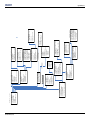
B: Menu Tree
B.1 OnScreen Menu Tree ..................................................................................................................B-1
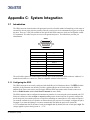
C: System Integration
C.1 Introduction .................................................................................................................................C-1
C.1.1 Configuring the GPIO .........................................................................................................C-1
C.1.2 Query Command .................................................................................................................C-2
C.1.3 Real Time Event ..................................................................................................................C-2
D: Optional Input Modules
D.1 DVI Input Module.......................................................................................................................D-1
D.2 Dual SD/HD-SDI Module...........................................................................................................D-1
vi
Roadie HD+35K User Manual
020-100340-02 Rev. 1 (01-2010)
1 Introduction
Every effort has been made to ensure the information in this document is accurate and reliable; however, due to
constant research, the information in this document is subject to change without notice.
1.1
Using this Manual
USERS/OPERATORS: This manual is intended for trained users authorized to operate professional high-
brightness projection systems, located in restricted areas, such as projection rooms in theatres. Such users may
also be trained to replace the lamp and air filter, but cannot install the projector or perform any other functions
inside the projector.
NOTE: Only personnel trained specifically by Christie on lamp replacement and lamp safety may handle the
lamp.
SERVICE: Only Christie accredited service technicians knowledgeable about all potential hazards associated
with high voltage, ultraviolet exposure, and high temperatures generated by the lamp and associated circuits
are authorized to 1) assemble/install the projector and 2) perform service functions inside the projector.
This manual contains the following sections:
•
•
•
•
•
•
•
•
•
•
Section 1 Introduction
Section 2 Installation and Setup
Section 3 Operation
Section 4 Maintenance
Section 5 Troubleshooting
Section 6 Specifications
Section Appendix A: Serial Communication Cables
Section Appendix B: Menu Tree
Section Appendix C: System Integration
Section Appendix D: Optional Input Modules
Disclaimer: Every effort has been made to ensure the information in this document is accurate and reliable.
However, due to constant research, the information in this document is subject to change without
notice. Christie Digital Systems assumes no responsibility for omissions or inaccuracies. Updates to
this document are published regularly, as required. Please contact Christie Digital Systems for
availability.
Roadie HD+35K User Manual
020-100340-02 Rev. 1 (01-2010)
1-1
Section 1: Introduction
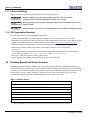
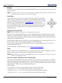
1.1.1 Labels and Marking
Observe and follow any warnings and instructions marked on the projector.
Danger symbols are used to alert situations where the user will become
seriously injured if they do not follow the advice in this section.
Warning symbols are used to alert situations where there is a situation where a user
may be injured.
Caution symbols are used to convey information where equipment damage will occur.
1.1.2 35K Typographical Notations
The following notations are used throughout this manual:
• Keypad commands and PC keystrokes appear in bold small caps, such as POWER, INPUT, ENTER etc.
• References to specific areas of the document appear italicized and underlined. When viewed online, the text
appears in blue indicating a direct link to that section. For example, Section 2 Installation and Setup.
• References to other documents appear italicized and bold, such as Service Manual.
• References to software menus and available options appear italicized, such as Main menu,
Preferences.
• User input or messages that appear on screen, in status display units or other control modules appear in
Courier font. For example. “No Signal Present”, Login: christiedigital.
• Error codes, LED status appear in bold, e.g. LP, A1, etc.
• Operational states of modules appear capitalized, such as switch ON/OFF.
1.2
Purchase Record and Service Contacts
Whether the projector is under warranty or the warranty has expired, Christie’s highly trained and extensive
factory and dealer service network is always available to quickly diagnose and correct projector malfunctions.
Complete service manuals and updates are available for all projectors. Should a problem be encountered with
any part of the projector, contact your dealer. In most cases, servicing is performed on site. If you have
purchased the projector, fill out the information below and keep with your records.
Table 1.1 Purchase Record
Dealer:
Dealer or Christie Sales/Service Contact Phone Number:
Projection Head Serial Number*:
First Lamp Serial Number:
Lens Serial Number:
Lamp Ballast Serial Number:
Purchase Date:
Installation Date:
*
1-2
The serial number can be found on the license label located on the back of the projector.
Roadie HD+35K User Manual
020-100340-02 Rev. 1 (01-2010)
Section 1: Introduction
At manufacture, the following Ethernet settings were defined in the projector:
Table 1.2 Ethernet Settings
Default Gateway
N/A
DNS Server
N/A
Projector DLP Address
1.3
Projector Mgmt IP Address
0.0.0.0 (ENABLES USE OF DHCP SERVER FOR IP ADDRESS)
Subnet Mask
255.255.255.0 (FIXED)
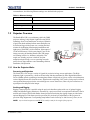
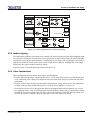
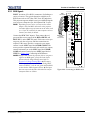
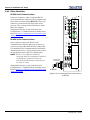
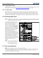
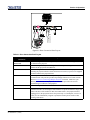
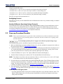
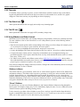
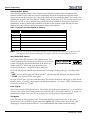
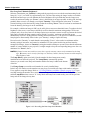
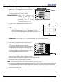
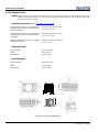
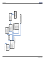
Projector Overview
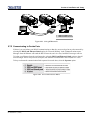
The Roadie HD+35K is a revolutionary split-body DMD
projector utilizing 3-chip Digital Light Processing (DLP)
technology from Texas Instruments. Its unique separation
of projection head and lamp ballast means both parts can
be flown and rigged with greater ease, creating the ideal
solution for challenging rental/staging installations and
tight spaces. With 2048 x 1080 resolution, light output of
32,500 ANSI lumens (35,000 centre lumens), and 10-bit
image processing all standard, Roadie HD+35K images
are stunning in their size, brilliance and quality. This
tough, user-friendly projector is built for frequent
transport and quick setup, even on sprawling networksperfect for any large audience venue demanding effortless
installation, and operation.
Up to 100 ft. Cables
Lamp Ballast (7kW)
1.3.1 How the Projector Works
Processing and Projection
The Roadie HD+35K accepts a variety of signals for projection in large screen applications. The High
brightness light is generated by a short-arc Xenon lamp, and then modulated by three Digital Micromirror
Device (DMDs) panels responding to incoming data streams of digitized red, green, or blue color information.
As these digital streams flow from the source, light from the responding "ON" pixels of each panel is reflected,
converged and then projected to the screen through one or more front lenses, where all pixel reflections are
superimposed in sharp full-color images.
Stacking and Rigging
Rigging a single projector is possible using the projector's handles together with a set of optional rigging
clamps and standard rigging techniques. Alternatively, a projector secured in an optional FredFrame™ can be
stacked and if desired, flown with another framed projection head using the rigging clamps provided in the
optional Rigging Kit. Each frame provides precision roll, pitch and yaw adjustments of the projector for
precision image alignments. Corresponding lamp ballasts can be locked up to 100 feet away, flown, or not.
NOTE: Any overhead suspension used MUST be suitably rated for the weight of the projector.
Roadie HD+35K User Manual
020-100340-02 Rev. 1 (01-2010)
1-3
Section 1: Introduction
1.3.2 List of Components
The following components make up a complete Roadie HD+35K system (refer to Figure 3-1):
• Projection Head. Includes:
• Line cord
• Standard IR remote (includes batteries for IR use, and 25’ cable for wired use)
• Security keys for lamp and Igniter service access, plus assorted Allen keys
• Lamp Ballast (7 kW)
• Cable kit (includes 2 lamp power cables and 2 communication/control cables)
• Choice of lamp kit (includes protective gear)
• Choice of lens (Anamorphic lens and mount are also both optional)
1.3.3 Key Features
General
•
•
•
•
•
3-chip electronics with true 2048 x 1080 native resolution
Split-projector design; ballast is separate from projection head
Versatile electronic and optical scaling to automatically maximize the display
10-bit digital processing (8-bit for interlaced high-definition video)
Can be rigged, flown and/or stacked with optional FredFrame™ hardware
Lamps / Light Output
•
•
•
•
•
•
•
Choice of four Xenon bubble lamp sizes and ratings
Light output of 32,500 ANSI lumens (35,000 centre lumens) (6kW lamp)
Standard achievable contrast ratio 500:1 ANSI, up to 2800:1 full field ON/OFF
LampLOC™ motorized lamp alignment (auto or custom adjustment)
LiteLOC™ for maintaining brightness over time
Internal electromechanical shutter for quick picture mute and black stand-by
Optional internal optical components for improved contrast ratio and/or wider color gamut
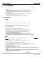
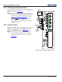
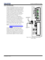
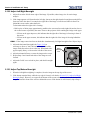
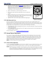
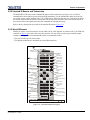
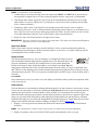
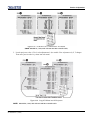
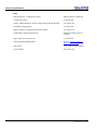
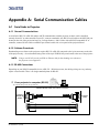
Inputs
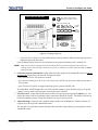
There are two different types of input face plate configurations (model dependant). Refer to Figure 1-1 and
Figure 1-2. These configurations may include the following inputs:
•
•
•
•
•
•
•
•
One analog RGBHV/YPbPr input with 5 BNCs
One DVI-I input for either digital RGB/YCrCb or analog RGB/YPbPr signals
One analog composite-video input, one analog S-video input
Built-in multi-standard decoder (NTSC, NTSC 4.43, PAL, PALM, PALN, PAL60, SECAM)
One Dual SD/HD-SDI input (installed in one of two optional input slots)
Up to 220 MHz pixel rate
Compatible with all current HDTV formats
Motion adaptive de-interlacing of 50 fps- and 60 fps-originated standard and high-definition interlaced
sources
• Inverse telecine de-interlacing of film-originated standard and high-definition interlaced material with 3:2
drop-down (60 fps) or 2:2 drop-down (50 fps).
For simplicity, this manual refers to the configuration shown in Figure 1-1 only.
1-4
Roadie HD+35K User Manual
020-100340-02 Rev. 1 (01-2010)
Section 1: Introduction
RS422
RS232
IN
Vert
Input 1
Sync
Hor /
Comp
Blue
Green
Red
Input 2
DVI
Input 3
Video
Input 4
S-Video
Ethernet
GPIO
Remote
RS232
OUT
Input 5
(Opt. 1)
Input 6
(Opt. 2)
Figure 1-1
In p u t 2
DVI
G P IO
E th e rn e t
RS422
R S 232
OUT
R e m o te
RS232
IN
In p u t 5
(O p t. 1 )
In p u t 6
(O p t. 2 )
Figure 1-2
Lenses
•
•
•
•
•
Choice of standard high-brightness zoom lenses (ranging from 0.8:1 up to 8.5:1)
Adjustable zoom, focus, and horizontal and vertical offsets
Optional lens mount for 1.26x anamorphic lens producing 2.39:1 "scope" images
Motorized Lens Mount to set focus, zoom, and horizontal and vertical offsets
Motorized Zoom kit (optional lens accessory) is available for lens upgrade
Special Display Functions (Selected Functionality)
•
•
•
•
Auto setup
Picture-in-Picture (PIP)
Electronic brightness uniformity, whitelevel edge blending and color matching
Optional image warping/blending for unusual angles and/or screens (Christie TWIST)
Roadie HD+35K User Manual
020-100340-02 Rev. 1 (01-2010)
1-5
Section 1: Introduction
Communications and Diagnostics
•
•
•
•
•
•
•
1-6
Built-in keypad and convertible IR-to-wired remote
Front and rear IR sensors
Ethernet, RS232, RS422, and GPIO control ports
Built-in ChristieNET™ connectivity and control
LED for two-digit error codes, plus LCD for text-based status display
Large status light for long-distance alerts
Double voltmeters: one for lamp ballast, one for projection head
Roadie HD+35K User Manual
020-100340-02 Rev. 1 (01-2010)
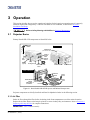
2 Installation and Setup
This section explains how to install, connect and optimize the projector for delivery of superior image quality.
Illustrations are graphical representations only and are provided to enhance the understanding of the written
material.
2.1
Projector Quick Setup and Installation
Follow these steps for quick setup of the projector in a basic front-mount position. Refer to the remaining
subsections for detailed setup instructions.
Always power down the projector and disconnect all power sources before servicing
or cleaning.
Refer to Section 4.1 Safety Warnings and Guidelines.
2.1.1 Quick Setup
1. Position the Projection Head.
Locate the projection head at an appropriate throw distance (projector-to-screen distance) and vertical
position. Refer to Section 2.3 Projector Position and Mounting and the Christie website for Throw
Distance calculations. Refer to Section 6.2 Lenses. Make sure that the projector is level from side-to-side,
and is not inverted. The projector’s front-to-back and side-to-side tilt can be no more than 15 degrees from
horizontal. Position the lamp ballast so that its four cables can reach the rear of the projection head.
2. Install the Lamp and Lens.
Refer to Section 2.4 Installing Lens, Lamp, and Cooling for installation instructions.
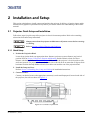
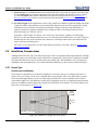
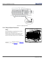
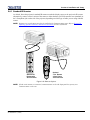
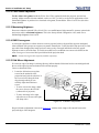
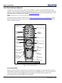
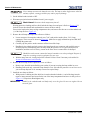
3. Connect a Source.
Connect your desired source to the appropriate connector(s) on the main Input panel, located on the side of
the projector (lens side) as shown in Figure 2-1.
Figure 2-1 Connect to Input Panel
Roadie HD+35K User Manual
020-100340-02 Rev. 1 (01-2010)
2-1
Section 2: Installation and Setup
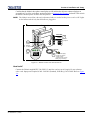
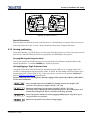
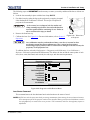
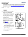
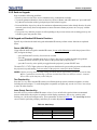
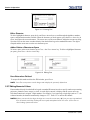
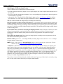
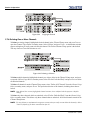
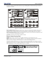
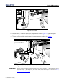
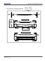
4. Connect to Lamp Ballast and Power.
1) Connect all four cables to the projection head prior to switching the ballast’s
breaker/power switch ON. 2) Follow all labeling exactly.
Head to Ballast
Connect all four ballast cables. There are two DC power cables, and two communication/control cables
between the projector rear and lamp ballast as shown in Figure 2-2.
Projector Rear
Figure 2-2 Connect Head to Ballast
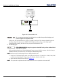
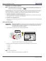
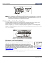
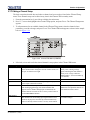
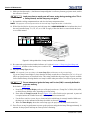
Ballast to AC
Refer to Figure 2-3.
NOTE: Before connecting the ballast to the AC supply, a Christie accredited service technician must make sure the
ballast's plug type and Input Power Range Switch match the line voltage available at the site. Remove the
lamp ballast cover to access the switch and determine it's setting-toggle LEFT for 200 VAC supplies,
toggle RIGHT for 400 VAC supplies (factory default=200 VAC). Change the plug type as necessary as a
delta load with safety ground has no neutral.
Connect the ballast's integral three-phase 30-amp line cord to your AC supply. You may have to change the
plug type for your site.
2-2
Roadie HD+35K User Manual
020-100340-02 Rev. 1 (01-2010)
Section 2: Installation and Setup
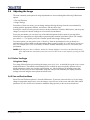
Confirm that the ballast's three-phase status lights are ON and that the adjacent voltmeter displays an
acceptable AC level for your ballast, and region. Refer to Section 6 Specifications for details. Then switch
the ballast’s breaker/power switch to the ON position.
NOTE: The ballast's internal fan is the only indication whether or not the breaker/power switch is ON. Lights
on the ballast indicate only that the ballast is plugged in.
NOTE: Internal Incoming Line Voltage switch setting must match AC available at the site.
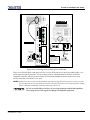
Interlocks
Control
+ DC
4.
1.
Connect
to projector
– DC
Breaker/Power
Switch in ON position
3.
3-phase
Check
status
Voltmeter (400V)
6’ line cord
2.
Connect to AC supply:
• 200 VAC in N. America
• 208 VAC in Japan
• 380/400/415 VAC in Europe
(Modify plug as necessary)
Figure 2-3 Ballast Connection and Switch On
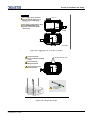
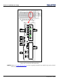
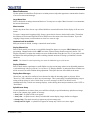
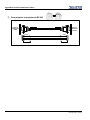
Head-to-AC
Connect the Christie-supplied IEC 320 (220V) 15-amp line cord to your AC supply. Do not substitute
other cords. Input power required is 200 - 240 VAC (nominal), 50/60 Hz @ 3A for 208V. Refer to Figure
2-4.
Roadie HD+35K User Manual
020-100340-02 Rev. 1 (01-2010)
2-3
Section 2: Installation and Setup
Projector Rear
To AC
200-240 VAC
Figure 2-4 Connect Head to AC
Do not attempt operation if the AC level is not within the specified voltage, and
power range for the projection head.
At this point, the projection head is in a type of "standby" mode only. The voltmeter should display the
incoming voltage, the adjacent main PROJ. STATUS light should be yellow, and the light engine
compartment fans running, but the rest of the projection head should be OFF.
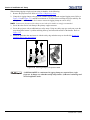
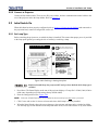
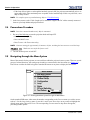
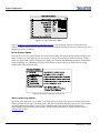
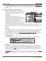
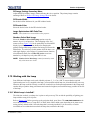
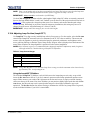
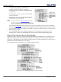
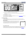
5. Set the lamp type.
EXPLOSION HAZARD. Keep the projection head OFF until you have defined which
lamp type is installed.
Before switching the projector ON and igniting the lamp, you must define in memory which size lamp is
installed; otherwise, you risk severely over driving or under driving a lamp.
NOTE: Ensure that you record the lamp size on the "Lamp Installed" label.
a. Press MENU. The Status Display at the rear of the projector shows a "Lamp Size" of 2000, 3000, 4500
or 6000 watts, depending on its last setting. The Factory default is 6000 watts.
b. Enter either the Lamp Password. Refer to Figure 2-5.
NOTE: The password is required unless the "Enable Password" service option has been turned OFF.
2-4
Roadie HD+35K User Manual
020-100340-02 Rev. 1 (01-2010)
Section 2: Installation and Setup
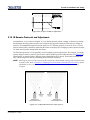
HOW TO SET THE LAMP SIZE:
1.
2.
Menu
Press “Menu” before power up.
Screen below displays lamp size.
Enter Lamp Password:
Input 3
1
Input 4
1
7
0
on built-in
keypad
or
1
3.
4
on the
standard
IR remote
Lamp Size
6000
Select installed lamp size:
2000
3000
4500
6000
Or standard Christie service password.
on built-in
keypad
or
on the
standard
IR remote
Figure 2-5 Setting Lamp Size
c. Use the UP/DOWN ARROWS to select which lamp is currently installed. Make sure the lamp type is also
indicated on the lamp door label.
Once the Status Display shows the correct lamp type, the projector and lamp can be switched ON.
NOTE: Lamp size can also be changed in the Service menu (Service password required) if the projector is
running, but it will not take effect until the next power-up. Whenever possible, define the lamp size before
igniting the lamp.
6. Switch the projector and lamp ON. Using either the built-in keypad or the standard IR remote, do one of
the following to switch the projector ON, and ignite the lamp:
• press and hold POWER for at least two seconds
• press POWER and then press the UP or DOWN Arrow key (useful if you are unsure of the present state of
the projector)
• press POWER twice quickly to toggle from the projector’s present ON/OFF state
The main PROJ. STATUS light at the rear of the projector should be green when the projector is up-andrunning. For best results, let the projector warm up for about 5 minutes.
7. Select the source. Using either the IR remote or built-in keypad, press the appropriate Input key (1-6) to
display the image for the corresponding source connected as described in Step 3. The display will resize as
needed, producing an image as large as possible for the type of source present.
8. Adjust the Image. Adjust the more common image settings, such as Brightness, Contract, Gamma, etc.
using the keys directly on the standard IR remote.
You can also access the Menu system and adjust these and other image settings by pressing MENU on the
standard IR remote.
Roadie HD+35K User Manual
020-100340-02 Rev. 1 (01-2010)
2-5
Section 2: Installation and Setup
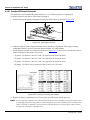
9. Adjust the lens. Use the Focus button on the standard IR remote or the built-in keypad to focus the image.
Use the Zoom buttons to increase or decrease image size (not available with fixed 0.8:1 and 1:1 lenses).
Use the Lens Shift button, and the ARROW keys to shift the image location. Refer to Section 3.14
Working with the Lenses on how to use the motorized lens mount and Section 2.4.1 Lens Installation for
instructions.
10. Set Cable Length. In the Lamp menu, set the "Cable Length (m)" slidebar to match the length of the highvoltage DC cables connected between your lamp ballast and projection head. This regulates the voltage
drop that occurs over distance, and ensures that adequate voltage reaches the lamp. Particularly in
projectors rented for temporary installations, this setting may have to be changed from its last use.
Adjustment range is 2-30m (6½-100 ft.).
Setting the "Cable Length" also allows you to achieve the same lumens, regardless of cable length.
However, to drive the lamp at maximum power, even with the shorter ballast cables, set "Cable Length" to
maximum power. Due to the resistance losses that occur with longer ballast cables, the ballast does not
achieve the same maximum power.
Press AUTO SETUP and/or MENU to refine other display parameters as necessary. Refer to Section 3.6.3
Image Settings Menu.
2.2
Installation Considerations
Although the Roadie HD+35K is carefully engineered to deliver exceptional quality, high brightness, and high
resolution output, your final display results could still be compromised if the projector is improperly installed.
This subsection discusses issues to consider before proceeding with a final installation. Even for temporary
installations, this information helps you to better understand what may be done to ensure optimized images.
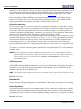
2.2.1 Screen Type
Front Screen Installations
This projector is intended for use with flat or slightly curved screens, front or rear, ranging from about 1.5
meters (5 ft.) to 45 meters (150 ft.) wide. Although flat screens generally offer a low gain similar to a matte
white wall paint-approximately 1 with a viewing angle just under 180°- and are considered most effective
when ambient light is low, this difference in gain may be negligible given the very high light output from this
projector. In addition, incident light reflects equally in all directions so the audience can see the display from
more acute viewing angles. See Figure 2-6.
Flat
Screen
(gain 1)
Viewing
Angle
Audience Coverage
Figure 2-6 Audience Coverage with a Flat Screen
2-6
Roadie HD+35K User Manual
020-100340-02 Rev. 1 (01-2010)
Section 2: Installation and Setup
NOTE: Roadie HD+35K lenses are designed primarily for use with flat screens, but the projector's depth-of-field
range allows the lens to be focused on mildly curved screens as well. While focus remains sharp in the
corners, there may be significant pincushion distortion, primarily at the top of the screen.
Rear Screen Installations
There are two basic types of rear screens: diffused and optical. A diffused rear screen has a surface that spreads
the light striking it. Purely diffused screens have a gain of less than 1. The main advantage of the diffused
screen is its wide viewing angle, similar to that of a flat screen for front screen projection. Optical rear screens
take light from the projector and redirect it to increase the light intensity at the front of the screen. This reduces
it in other areas, and creates a viewing cone similar to that of a curved front screen installation.
To summarize, optical screens are better suited for brightly lit rooms where the audience is situated within the
viewing cone. Diffused screens may be better suited when a wide viewing angle is required, but there is low
ambient room lighting.
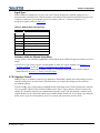
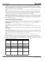
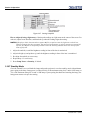
2.2.2 Screen Size
Screen size (image size) may be up to 150 feet across, depending on your lens and ambient light level. Choose
a screen size appropriate for your lens and application. Keep in mind that if the projector will be used to
display much text information, the image size must allow the audience to recognize all text clearly. The eye
usually sees a letter clearly if eye-to-text distance is less than 150 times the height of the letter. In other words,
small text that is simply located too far from the eye will be illegible no matter how sharply and clearly it is
displayed.
NOTE: Screens with aspect ratios (proportion) of 4:3 are typically specified by diagonal size, but screens having
other aspect ratios, such as the 2048 x 1080 of the Roadie HD+35K, are usually specified by their
horizontal width. See Table 2.1 below:
Table 2.1 Matching Lens to Screen Size
Lens Type
Screen Width(< - >)
0.8:1 fixed
5 - 3 ft.
1:1 fixed
14 - 150 ft.
1.25 - 1.45:1 zoom
10 - 121 ft.
1.45 - 1.8:1 zoom
8 - 102 ft.
1.8 - 2.4:1 zoom
6 -83 ft.
2.2 - 3.0:1 zoom
5 - 66 ft.
3.0 4.3:1 zoom
3 - 49 ft.
4.3 - 6.0:1 zoom
2.5 - 35 ft.
5.5 -8.5:1 zoom
2 - 27 ft.
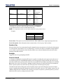
2.2.3 Screen Aspect Ratio
Aspect ratio describes the proportion of the display and is expressed as the ratio of width to height, such as
"5:4" or "16:9". Typical aspect ratios range from 1.25 to 2.35, the higher the value, the wider or "less square"
the image. Refer to Table 2.2 below.
Roadie HD+35K User Manual
020-100340-02 Rev. 1 (01-2010)
2-7
Section 2: Installation and Setup
Table 2.2 Typical Aspect Ratios
Application
Aspect Ratio
SXGA
1.25 (5:4)
35mm filmstrip
1.32 (4:3)
NTSC Video/XGA
1.33 (4:3)
PAL Video/XGA
1.33 (4:3)
HDTV Video
1.78 (16:9)
Letterbox Video/”Flat”
1.85 (2048 x 1080)
Roadie Native Resolution
1.89 (2048 x 1080)
Cinemascope
2.35
Although image size and aspect ratio can be adjusted using projector software, it is still ideal to use a screen
with an aspect ratio that closely matches your likely source material. You can then more easily fill the screen
with the image without restricting either image size or content. For example, standard video from a VCR has a
4:3 ratio (approximately) and can fill a 4:3 screen without side-to-side stretching, whereas a high-definition
signal with a 16:9 aspect is largest on a 16:9 screen.
Image edge
Screen edge
5:4 image
Screen edge
16:9 image
on
on
16:9 screen
5:4 screen
Image edge
Figure 2-7 Aspect Ratios: Image vs. Screens
As shown in Figure 2-7, an obvious mismatch between source material and screen is characterized by "black
bars" on both sides of the image (if the screen is wider than the source material) or above and below the image
(if the source material is wider-typically called a letterbox display).
Alternatively, if the area of unused pixels is considered minimal, you may prefer to use the projector's software
control to slightly stretch the image either horizontally or vertically-enough to utilize the remaining pixels
while not noticeably distorting the image.
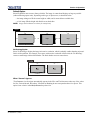
Using a Cinema "Flat" Screen (1.85 aspect ratio)
By default, source signals closely matching the projector's 2048 x 1080 display area will fill this area
accordingly. Signals with lower aspect ratios will automatically scale to be as large as possible while
maintaining their original aspect ratio. For details on resizing behavior, refer to Section 3.6.3 Image Settings
Menu.
2-8
Roadie HD+35K User Manual
020-100340-02 Rev. 1 (01-2010)
Section 2: Installation and Setup
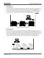
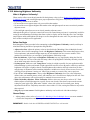
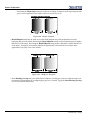
Displaying both “Flat" and "Scope"
As an example, two standard types of displays (flat and scope) differ in their width-to-height aspect ratio as
shown below:
“Flat” Image
Aspect ratio = 1.85
“Scope” Image
Aspect ratio = 2.39
Figure 2-8 Typical Wide Formats
Achieving either of these displays from a variety of incoming source material (that may or may not be in the
same format) depends on proper settings in the projector as well as certain room conditions.
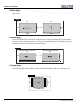
Projector Variables: Electronic and Anamorphic Resizing
The native resolution of the projector (1.89) closely matches the aspect ratio of "flat" source material (1.85).
Wider scope material, however, may be "squeezed" electronically that is, it is distorted into a narrower area
(characterized by unusually thin people) so that its pixels can then be stretched horizontally through the
anamorphic lens to regain the full and properly proportioned 2.39 display. This optical widening can stretch the
image by approximately 25%. See Figure 2-9.
Normal “Scope” Image
ph
or
am
An
Unused pixels
Screen edge
Figure 2-9 Typical Method for Achieving “Scope”
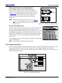
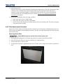
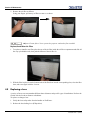
Masking Options
In order to conveniently present different types of incoming data-for example, flat vs. scope-on a single screen,
you can use physical masking to cover the unused edge(s) of the screen. These movable panels are most
commonly installed along the top edge of the screen, changing the height of the screen, but not its width, and
are most frequently used in permanent installations.
The screen shown in Figure 2-10 also has a bottom mask:
• Add masks for "scope" displays
• Remove masks for "flat" displays
Roadie HD+35K User Manual
020-100340-02 Rev. 1 (01-2010)
2-9
Section 2: Installation and Setup
TOP-MASKING SCREEN
(1.85 screens)
2.39 image
Top/bottom masking
to hide screen edges
1.85 image
Masking moved
aside
Figure 2-10 Top Masking for Scope Images
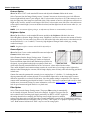
Alternatively, masks may be installed at each side of the screen in order to change the width of the screen, but
not its height.
• Add masks for "flat" displays
• Remove masks for "scope" displays
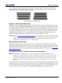
In some cases, the room will have both side and top/bottom masking installed. This arrangement is the most
flexible of all.
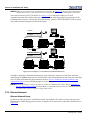
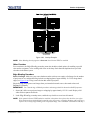
Refer to Figure 2-12 for a summary of the basic factors affecting wide displays in a variety of rooms.
SIDE-MASKING SCREEN
(2.39 screens)
Side masking to hide screen edges
1.85 image
2.39 image
Masking moved aside
Figure 2-11 Side Masking for Flat
2-10
Roadie HD+35K User Manual
020-100340-02 Rev. 1 (01-2010)
Section 2: Installation and Setup
Screen Type
SIDE-MASKING SCREEN
(2.39 screens)
“All the Pixels All the Time”
Masking
Quickest Scope --> Flat
ph
or
am
An
Flat
Masking
Flat
(1700 across)
ph
or
am
An
ph
or
am
An
Scope
Scope
(2048 across)
TOP-MASKING SCREEN
(1.85 screens)
Flat
ph
or
am
An
Masking
Flat
Scope
Re-size electronically with TPC
source & screen settings
Scope
NOTE: Example shows vertical offset
EXTRA SHORT THROW
and
1280 -->1700 (approx.)
M
FIXED SIDE MASKING
Z OO
out
(1700 across,
approx.)
1280 --> 2048
(Masking)
Top and/or bottom masks present
ZOOinM
ph
or
am
An
Flat
ph
or
am
An
Scope
Figure 2-12 Switching between Flat and Scope Displays
2.2.4 Ambient Lighting
The extraordinary brilliance of this projector is certainly well suited for locations where ambient lighting might
be considered less than ideal for projection. Even a typical room or large auditorium fully lit with ceiling lights
and windows rarely requires special attention. Contrast ratio in your images will be noticeably reduced only if
light directly strikes the screen, such as when a shaft of light from a window or floodlight falls on the image.
Images may then appear washed out and less vibrant.
In general, avoid or eliminate light sources directed at the screen.
2.2.5 Other Considerations
Other considerations and tips that can help improve your installation:
• Keep the ambient temperature constant and below 35°C (95°F). Keep the projector away from heating and/
or air conditioning vents. Changes in temperature may cause drifts in the projector circuitry that may affect
performance.
• Keep the projector away from devices that radiate electromagnetic energy such as motors and transformers.
Common sources of these include slide projectors, speakers, power amplifiers, elevators, etc.
• Choose the best screen size for the application. Since more magnification reduces brightness, use a screen
size appropriate for the venue, but not larger than required. Installing a large screen in a small room is similar
to watching television at a close range; too large a screen can overpower a room and interfere with the overall effect. A good rule of thumb is to be no closer than 1.5 times the width of the screen.
Roadie HD+35K User Manual
020-100340-02 Rev. 1 (01-2010)
2-11
Section 2: Installation and Setup
2.3
Projector Position and Mounting
Installation type, the available screen, and ambient lighting all affect where the projector should be positioned.
In addition, both throw distance (the distance between the projector and screen) and vertical position (the
height of the projector in relation to the screen) must be determined for every new installation. Both depend on
the screen size and lens type you are using. Make sure that the room can accommodate the required location of
the projector for the chosen screen size.
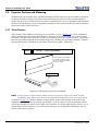
2.3.1 Throw Distance
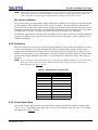
Throw distance is the distance between the projector and the screen (see Figure 2-13). For any installation,
placing the projector at an accurate throw distance is necessary in order for the image size to closely match
your screen. The farther the projector is from the screen, the larger the image. With zoom lenses, you'll want to
know the approximate minimum and maximum image sizes possible from a given throw distance so that the
most appropriate lens is installed at the site (throw distance/screen width = throw ratio).
Screen
x
Lens Type = Approx. Throw Distance
In this example, a throw distance of
18.75 feet will project an image
approx. 13-15 ft wide, depending
on the zoom setting.
1.25-1.45 zoom lens
Figure 2-13 Estimating Throw Distance: Example
NOTE: If your projector is slightly tilted in relation to the screen, typical for large venues and/or elevated
installations, throw distance still represents the smallest measurement between the screen and projector.
As shown in Figure 2-13, the throw distance is approximately equal to the horizontal width of the screen
multiplied by the type of lens you are using. For example, if you are using a 1:1 lens, proper throw distance
will be approximately the same as screen width. Once you know your screen width and type of lens, you can
estimate throw distance needed. Or, if you know throw distance, you can determine what images sizes are
possible with a given zoom lens.
2-12
Roadie HD+35K User Manual
020-100340-02 Rev. 1 (01-2010)
Section 2: Installation and Setup
IMPORTANT! For proper placement in any installation, use the lens and screen size to calculate the precise
throw distance using the tables provided in the Dealer Section of the Christie Website, PN 020100395-xx. In addition, please keep in mind that due to lens manufacturing tolerances for lens
focal length, actual throw distance can vary ±5% or more between lenses described as having the
same throw ratio.
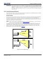
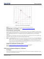
2.3.2 Vertical & Horizontal Position
Refer to the offsets shown in this section to help determine how high or low to install the projector in relation
to the center of the screen, and/or how far off to one side.
Vertical Position
Describes the elevation of the projector in relation to the screen. For many typical rental/staging installations,
the projector is mounted above screen center. An ideal vertical position helps to ensure that images are
accurately rectangular in shape rather than distorted into a keystoned shape with non-parallel sides, that both
image focus, and brightness remains optimized.
NOTE: Proper vertical position is recommended, although vertically keystoned images (i.e., those with sloping
sides) can be corrected in software. Refer to Section 3 Operation.
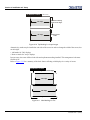
The image can be offset vertically (shifted above or below lens center) by using the built-in keypad or the
standard IR remote. Starting with no offset, the 2048 x 1080 image from this projector can be moved by a
distance of up to ±100% of the image height (depending on the lens), resulting in the entire image being
displayed above or below lens center. Refer to Figure 2-12.
Figure 2-14 Vertical Offset Range
Roadie HD+35K User Manual
020-100340-02 Rev. 1 (01-2010)
2-13
Section 2: Installation and Setup
NOTES: 1) Assumes full 2048 x 1080 display. 2) Recommended offset range can sometimes be exceeded, however
this may affect image quality. 3) Due to manufacturing tolerances, an offset range can vary ±5% or more
between lenses described as having the same throw ratio, between projectors, and with any lens/projector
combination. 4) Simultaneous horizontal and vertical offset can limit the adjustment range of each, as can
long throw distances.
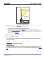
ALTERNATIVE METHOD OF DESCRIBING VERTICAL OFFSET
Offset can also be specified as the distance traveled from lens center (such as 270 pixels) and expressed as
a percentage (270 pixels=50%) of half of the image height. This concept of image movement is illustrated
in the example below:
50% Offset
Image moved by a distance of
50% of half the image height
75%
of image
lens center
25%
of image
Figure 2-15 Example of Alternative Offset Specification
For any projector, if you find that you cannot raise or lower the image enough using mechanical vertical
offset, try adjusting V-Position in the Size and Position menu when displaying at less than the minimum
size (see Section 3.6.3 Image Settings Menu). If images remain keystoned or exhibit uneven brightness, the
projector may simply be too high or low in relation to the screen. Relocate for optimized performance.
Horizontal Position
The image can be offset horizontally (shifted left or right of lens center) by using the built-in keypad or the
standard IR remote. Starting with no offset, the 2048 x 1080 image from this projector can be moved by a
distance of up to ±35% of the image width (depending on the lens).
2-14
Roadie HD+35K User Manual
020-100340-02 Rev. 1 (01-2010)
Section 2: Installation and Setup
70% Offset
15%
85%
Image moved by
a distance of 70%
of half the image
width
NOTE: Not possible
with this projector.
Figure 2-16 Horizontal Offset Range
NOTE: The positioning shown in Figure 2-16 is often mistakenly referenced as "70% offset", but it is not-it is 40%
offset derived as 432/1080 x 100. A 70% offset is explained below.
ALTERNATIVE METHOD OF DESCRIBING HORIZONTAL OFFSET
Horizontal offset can also be specified as the distance traveled from lens center and expressed as a
percentage of half of the image width. For example, an offset spec of 70% means a centered image can be
moved by a distance of 540 pixels, resulting in 85% of the image projected to one side of lens center and
15% on the other. See Figure 2-16.
NOTE: Example only. Beyond range for this projector.
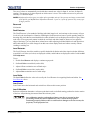
2.3.3 Floor Mounting and Leveling
For front projection without suspending, mount the projector on a strong supporting structure or cart. Take
special care if using a mobile cart-avoid sudden stops, force and uneven surfaces that may cause the top-heavy
cart to lurch and overturn.
Make sure your mounting structure is reasonably level, and then adjust one or more projector feet as necessary
to fine-tune.
Do not invert this projector.
Adjusting the Feet
For installations on a floor or suitable supporting structure, a single projection head should rest firmly on its
feet. To adjust the height and level of the projector, extend or retract the feet by rotating them. Refer to Figure
2-17.
Roadie HD+35K User Manual
020-100340-02 Rev. 1 (01-2010)
2-15
Section 2: Installation and Setup
Figure 2-17 Adjusting the Feet
2.3.4 Tilting and Special Orientations
± 15° max.
Tilting
For any installation, you can tilt the front end of the
projector up or down as much as 15°.
Likewise, side-to-side tilt must not exceed 15° (see ).
This limit ensures safe lamp operation and proper
position of the liquid cooling reservoir in the projector.
± 15° max.
Tilt only as shown in Figure 2-18
and Figure 2-19.
2-16
Figure 2-18 Front End Tilt
Roadie HD+35K User Manual
020-100340-02 Rev. 1 (01-2010)
Section 2: Installation and Setup
Max.
±15°
Figure 2-19 Side to Side Tilt
Special Orientations
Since this projector cannot be inverted or tilted beyond 15°, all installations are typically front-mount or rearmount and require the "Front" or “Rear” Image Orientation setting in the Configuration menu.
2.3.5 Hoisting and Stacking
For most installations, you will likely have to safely lift or hoist this projector-or a stack of two projectors-into
place. Keep in mind the following critical safety guidelines for all handling of the projector.
Carrying/Moving the Projection Head
Four or more people can lift and hand-carry one projection head a short distance using the handles or the
optional FredFrame™ , if installed. NEVER carry a stack of projectors.
Hoisting/Rigging a Single Projection Head
A single projection head can be hoisted and/or suspended using its handles, a set of rigging clamps (#113102101-xx), and appropriate rigging and safety cables. If desired, the lamp ballast can also be flown from its
integral rigging bars. To hoist, stack or "fly" a stack of projectors you must use the optional FredFrame™.
Refer to Using the FredFrame™ described below.
Read the following safety warning before hoisting/ rigging ONE projection head. Refer to 020-100133XX for more information.
Any overhead suspension used MUST be suitably rated for the weight of the
projector. The projector’s weight is 435 lb / 197.3 kg.
Maximum load rating of the projector's handles is 435 lb / 197.3 kg.
Use straps and/or cabling with load capacity adequate for the total projector and
handles when lifting/hoist. Never exceed the load rating specified.
Use the projector’s handles for hoisting/rigging ONE projector only. Never try to
carry more than one projector.
Remove the projection lens before hoisting/rigging.
Roadie HD+35K User Manual
020-100340-02 Rev. 1 (01-2010)
2-17
Section 2: Installation and Setup
When hoisting/rigging a single projector using its handles, do the following:
1. Remove the projection lens. Refer to Section 4.5 Replacing a Lens.
2. Clamp the 4 rigging clamps to the projector's handles staying within the assigned rigging zones. Refer to
Figure 2-20 and Figure 2-21, and allow a minimum of 12 inches between clamps for proper stability. Do
not tighten the cross bolt of the clevis arms to ensure the rigging clamp can swivel freely.
NOTE: Symmetrical placement of the clamps on each side of the handles is strongly recommended.
3. Secure the other end of each clamp to the primary support structure.
4. Secure the projector with an additional two safety straps. Using one safety strap per crossbeam, route the
strap through the bottom 2 eyebolts and bring them up, and around the outside of the handles. Refer to
Figure 2-21.
5. Install the projection lens and secure it with the safety ring and tether strap as described in Section 2.4
Installing Lens, Lamp, and Cooling.
Clevis
Maintain
swivel
Figure 2-20 Securing Clamps to Projection Head
1) CRITICAL SAFETY is a minimum of 4 rigging clamps are required for a single
projector. 2) Always use redundant safety straps/cables. 3) Observe load ratings and
all local applicable codes.
2-18
Roadie HD+35K User Manual
020-100340-02 Rev. 1 (01-2010)
Section 2: Installation and Setup
Rigging Zones
Use of 4 rigging clamps, positioned
within the assigned rigging zones, is
mandatory when hoisting/rigging.
= rigging zone
Allow at least 12 inches between clamps
to ensure stable hoisting/rigging.
Symmetrical placement of clamps
recommended.
TOP VIEW
12” min.
12” min.
between clamps
BOTTOM VIEW
Figure 2-21 Rigging Zones on Projector Handles
Use two safety straps one per crossbeam for additional
security.
Use 4 bottom eyebolts to secure
an additional two safety straps.
Route safety straps
though both eyebolts
Route safety strap around
outside of handles.
BOTTOM VIEW
Route a safety strap
through both eyebolts
on crossbeam.
Figure 2-22 Using Safety Straps
Roadie HD+35K User Manual
020-100340-02 Rev. 1 (01-2010)
2-19
Section 2: Installation and Setup
Using the FredFrame™
To hoist, stack and/or "fly" projectors using the optional FredFrame™ (PN 38-814007-xx), you must first
remove the handles and properly secure each projection head within a FredFrame™. Then using appropriate
rigging clamps (PN 38-814007-51), you can raise and/or suspend the projector assembly. If desired, the lamp
ballast can also be hoisted and flown from its integral rigging bars. Follow the instructions provided with the
FredFrame™ kit.
1) Use straps and/or cabling with load capacity adequate for the total projection
head and frame weight. 2) Remove the lens before hoisting. 3) Critical safety means
to never exceed the Load Rating specified in the FredFrame™ Stacking & Rigging Kit
instructions.
Refer to the complete instructions for using the FredFrame™. These include all installation instructions as well
as mechanical adjustment procedures for proper image alignment.
Using a Fork Lift
Do not attempt to use a forklift without first installing the forklift rails on the bottom
of the FredFrame™, otherwise the base of the projector may crush and damage
internal components.
Strong extruded rails that mount to the bottom of the FredFrame™ accommodate forks from a forklift, and are
mandatory for this method of transport. Do not lift the projection head with equipment unless the FredFrame™
and forklift rails are installed. The projector's handles must be removed when installing the FredFrame™.
Follow the instructions provided with the FredFrame™ kit.
Stacking
To stack two projection heads together, you must first secure each head within a FredFrame™, and then secure
all corners of the frames together using 4 stacking pins (provided). Do not stack more than 2 projection heads
together, and do not attempt to move stacked projectors without proper transport equipment. Refer to the
instruction provided with the FredFrame™ Kit for stacking.
2.4
Installing Lens, Lamp, and Cooling
It is recommended that the lens and lamp installation be handled at the last possible moment to ensure that no
damage is done to the projector due to movement.
2.4.1 Lens Installation
Primary Lens
1. Remove the rear lens cap from the lens.
2. Rotate the lens clamp to the OPEN position.
3. Orient your primary lens with its UP label at the top and fully insert the assembly straight into the lens
mount opening all the way back, without turning.
NOTES: 1) Ensure that the Zoom connector is fully engaged. 2) When installing the lens, ensure that the lens is
NOT inserted at an angle, as this can cause damage. 3) Ensure that the lens is fully back to seat
properly within the lens mount.
2-20
Roadie HD+35K User Manual
020-100340-02 Rev. 1 (01-2010)
Section 2: Installation and Setup
The following steps are IMPORTANT! and necessary to ensure your safety and that of the lens so it does not
fall out.
4. Lock the lens assembly in place with the lens clamp DOWN.
5. For added security, tether the lens to the projector by wrapping it around
either the handle or FredFrame™ if flown. This step is not required if
projector is floor-mounted.
In the event a lens is dropped, the lens tether and
clamp assembly may become stressed, and therefore
must be replaced before continuing its use. Failure to
do so could result in injury or death.
6. Remove the front lens cap.
7. Calibrate the lens. See Figure 2-24. For more information, refer to Section 3
Operation.
Figure 2-23 Tether Lens
to Projector
Lens calibration must be performed each time a new lens is inserted or after
performing manual lens mount adjustments. This is critical to the projector
functioning properly. Failure to do so could result in damage to the lens mount, the
projector, or the projection lens.
To calibrate the lens, select the Configuration > Diagnostics and Calibration > Lens Calibration >
Reference Calibration option from the Main menu. This allows the lens to find the center points of each
axis (focus, zoom, horizontal, and vertical), the end stops, and other motion parameters.
1.
2.
3.
4.
5.
6.
7.
8.
9.
0.
Diagnostics and Calibration
Test Pattern
Grid
Grey Level
512
Freeze Image
Color Enable
White
Odd Pixel Adjustment
Reserved
Peak Detector
Level Detector
Level Value
512
Aspect Ratio Overlay
Lens Center
Reference Calibration
ILS Calibration
Figure 2-24 Diagnostic and Calibration Menu
Lens Center Command
This command moves the lens horizontal and vertical motion to the center of travel.
NOTES: 1) The lens seals the projection head, preventing contaminants from entering the area of main electronics.
Never attempt to operate the projector without a lens installed. During transport and installation, install a
lens plug. 2) Always re-install a lens in its previous "UP" orientation, otherwise boresight may require readjustment.
Roadie HD+35K User Manual
020-100340-02 Rev. 1 (01-2010)
2-21
Section 2: Installation and Setup
Anamorphic Lens Installation (Optional)
NOTE: The optional anamorphic lens mount is required for use of the 1.26x anamorphic lens, producing 2.39:1
"scope" images. However, the lens mount cover must be removed when installing the anamorphic lens
mount and in order to the use the MALM.
If the anamorphic lens is used, it is recommended that you add the lens and its mount before final leveling or
making any adjustments (i.e. boresight, etc.). Install only for those installations requiring full-size 2.39:1
"scope" display (mostly side-masking screens) obtained by optically stretching a pre-squeezed image.
1. Install the Anamorphic Lens Mount on the Projector.
At the front of the projector, install the anamorphic lens mount hardware as described in the instructions
provided with Christie's Anamorphic Lens Mount Kit.
2. Install the 1:26x Anamorphic Lens.
Clamp the 1.26x anamorphic lens mount in place, following the instructions provided with the anamorphic
lens mount kit.
2.4.2 Install First Lamp
Explosion Hazard. Wear authorized protective clothing whenever the lamp door is
open. Never apply a twisting or bending force to the quart lamp body. A Christie
accredited service technician is required.
1. Open the lamp door and remove lamp cooling compartment door.
Open lamp door
with Key
Lamp Cooling Compartment Door
Reflector
Figure 2-25 Open Lamp Door and Cooling Compartment
2. Install one of the following lamps in the projection head, depending on your model and site:
• 2.0 kW*
• 3.0 kW*
• 4.5kW*
• 6.0 kW*
NOTE: 3-phase Ballast Required.
* Available as CDXL (maximum performance) or original CXL.
2-22
Roadie HD+35K User Manual
020-100340-02 Rev. 1 (01-2010)
Section 2: Installation and Setup
Refer to Section 6 Specifications.
1. Check lamp cradle (Anode end) location for your
lamp.
• For 4.5 or 6.0 kW lamps, the lamp cradle should use
the holes farthest from the reflector (factory
default).
Anode
Connector
Reflector
• For 2.0 or 3.0 kW lamps, use the holes closest to the
reflector.
2. Install lamp.
Lamp
Cradle
Refer to Section 4.4 Replacing the Lamp & Filter,
Steps 7-11 for installation instructions.
NOTES: 1) Observe all warnings, and wear protective
clothing and shielding. 2) Do Not forget to properly
mark the "Lamp Installed" label on the lamp door
to indicate current lamp size.
Liquid Cooling
During operation, a closed loop of flexible tubing
circulates liquid coolant from a small reservoir to critical
electronic components located near the front of the
Figure 2-26 Move cradle back for 2.0 or 3.0
projection head. The coolant (a 50/50 mix of distilled
water and ethylene glycol) should fill slightly more than
half of the reservoir to ensure adequate circulation. The reservoir, which is located in the Igniter compartment,
is factory-filled and does not require draining for transit. Check regularly.
2.5
Connecting Sources
Sources connect to the Input Panel located on side of the projector closest to the lens. Refer to Figure 2-27.
The upper left corner (INPUT 1) typically accepts an RGB signal from an external analog RGB source, or it
can also be used for YPbPr signals. Just beneath these BNCs, the DVI-I connector (INPUT 2) accepts digital
or analog display signals from a computer. An HDMI to DVI adapter cable accepts digital signals from a BluRay or DVD player. Connect analog composite video at INPUT 3 or S-video at INPUT 4 from devices such as
VCRs or DVD players. At INPUT 5, connect serial digital YCbCr (4:2:2) or compatible SMPTE signals (note
this module can be moved to INPUT 6. if desired).
There are also several optional interfaces available for connecting other sources, these interfaces slide into
either Input 5 or Input 6, and can be removed or installed while the projector is running.
NOTE: Some Input options are not available with some projector models.
Roadie HD+35K User Manual
020-100340-02 Rev. 1 (01-2010)
2-23
Section 2: Installation and Setup
Input 1
Vert
D
Sync
B
OUTPUT
A
Blue
INPUT 5
Serial Digital
C
INPUT 1
Analog Graphics
or
Component Video
FROM
Hor /
Comp
Green
B
Input 5
(Opt. 1)
INPUT 3
Composite Video
includes decoder
INPUT 4
INPUT
Dual SD HD-SDI 38-804656
Input 2
DVI
SIGNAL
INPUT 2
Analog or Digital
DVI
A
ACTIVE
Red
Input 3
Video
Input 4
S-Video
S-Video
includes decoder
Ethernet
INPUT 6
Various
(see Appendix)
Remote
RS422
GPIO
RS232
IN
RS232
OUT
Input 6
(Opt. 2)
Control
ports
Figure 2-27 Roadie HD+35K Input Panel
NOTES: 1) Refer to Section 6 Specifications for details regarding compatible inputs. 2) Use high quality shielded
cables only for all connections.
2-24
Roadie HD+35K User Manual
020-100340-02 Rev. 1 (01-2010)
Section 2: Installation and Setup
2.5.1 RGB Signals
BNC
connectors
Input 1
Vert
OUTPUT
B
A
FROM
Hor /
Comp
Blue
C
NOTE: Depending on your source, you may need a custom
Green
Input 5
(Opt. 1)
B
adapter cable with BNC connectors at the projector
end and a different type of connector at the other (such
as a 15-pin "D" connector for some computer sources).
Contact your dealer for details.
Input 2
DVI
RGB and Sync
signals
from source
INPUT
SIGNAL
ACTIVE
Red
Dual SD HD-SDI 38-804656
Connect the SYNC BNC input(s). Then connect the red,
green and blue source outputs to the RED, GREEN, and
BLUE BNCs on the INPUT 1 panel. If the source uses syncon-green, only the red, green, and blue connections are
required. If the source provides a composite sync output,
connect it to the SYNC input labeled HOR/COMP. If the
source provides separate horizontal and vertical sync outputs,
connect horizontal sync to the SYNC input labeled HOR/
COMP and connect vertical sync to SYNC input labeled
VERT. See Figure 2-28. Connecting an RGB Source.
D
Sync
A
INPUT 1 consists of five BNCs (connectors) for linking to a
variety of sources. The typical connection would be to an
RGB source such as a PC, Mac, DEC, Sun, SGI and others.
This projector supports multiple sync types with RGB signals:
sync-on-green, composite sync, and separate H & V syncs.
Input 3
Video
Input 4
S-Video
Ethernet
Remote
RS422
GPIO
RS232
IN
RS232
OUT
Input 6
(Opt. 2)
NOTES: 1) If for some reason the projector fails to recognize a
signal as an RGB signal, specify this Color Space
option within the Image Settings menu. Refer to
Section 3.6.3 Image Settings Menu. 2) To connect
YPbPr signals-such as from DVDs or analog HDTV
sources-to INPUT 1, use the red, green and blue BNCs
as described in YPbPr Signals (below). 3) This Input
does not route to the decoder and cannot be used for
Composite Video or S-Video.
Roadie HD+35K User Manual
020-100340-02 Rev. 1 (01-2010)
Figure 2-28 Connecting an RGB Source
2-25
Section 2: Installation and Setup
2.5.2 YPbPr Signals (Component Video).
NOTE: Unlike previous Christie projectors, composite
D
B
OUTPUT
Pb
A
FROM
Hor /
Comp
C
Blue
Green
Input 5
(Opt. 1)
B
Y
29-pin DVI-I
Connector
Input 2
DVI
INPUT
Red
Pr
Dual SD HD-SDI 38-804656
INPUT 3 and INPUT 4 provide simultaneous connection
of both a composite video source (INPUT 3 and an SVideo source (INPUT 4). Refer to Figure 2-30.
Vert
Sync
SIGNAL
2.5.3 Composite Video
Input 1
ACTIVE
recognize a YPbPr signal, specify this Color Space
option within the Image Settings menu. Refer to
Section 3.6.3 Image Settings Menu. 2) Do not
connect digital component signals (known as
YCbCr) to INPUT 1 or INPUT 2. Use the
appropriate optional digital interface installed in
INPUT 5 or 6 only.
A.k.a.:
• Component
• YUV
• Y, R-Y, B-Y
A
NOTES: 1) If, for some reason, the projector fails to
Signals
from YPbPr
source
BNC
connectors
Connect a YPbPr signal (component video) to INPUT 1 or
INPUT 2 as shown in Figure 2-29.
Input 3
Video
To YPbPr
source
Input 4
S-Video
video and S-Video cannot connect to any other
locations on the Input panel. Connect as shown in
Figure 2-30.
Ethernet
Remote
RS422
GPIO
RS232
IN
RS232
OUT
Input 6
(Opt. 2)
Figure 2-29 Connecting a YPbPr Source
2-26
Roadie HD+35K User Manual
020-100340-02 Rev. 1 (01-2010)
Section 2: Installation and Setup
2.5.4 Dual SD/HD-SDI
Christie's Dual SD/HD-SDI module is standard with
this projector and factory-installed in the first option
slot (labeled INPUT 5). Its loop-through capability
enables incoming serial digital data (HD format) to
be tiled across multiple screens, creating vast "mega
resolution" displays. Alternatively, the multiple
outputs can be overlapped for extra-bright displays,
or simply distributed to additional projectors for
multiple screens of the same image.
Vert
Connect a compatible SMPTE 292M or SMPTE
259M-C source(s) to one or both of the inputs
located on the left side of the module. The module
automatically detects the standard at each input and
configure itself accordingly for correct termination
of the signal. The module also detects and supports
dual link 292M for SMPTE 372M video standards.
B
OUTPUT
A
FROM
Hor /
Comp
C
Blue
Green
B
Input 5
(Opt. 1)
Dual SD HD-SDI 38-804656
Input 2
DVI
INPUT
From Composite
Video Source
SIGNAL
ACTIVE
Red
Input 3
Video
Input 4
S-Video
NOTE: Selection of these inputs is described in
Section 3.2 Using the Built-In Keypad or
Remotes.
D
Sync
A
The module accepts one or two independent
standard- or high-definition serial digital inputs,
decodes them for processing in the main electronics
of the projector, and outputs 10-bit RGB/YCbCr
4:2:2 video. Either input can be set as the active
primary or secondary part of a Picture-in-Picture
(PIP) display, and either input can be looped through
to one (or both) of the module's BNC outputs.
Input 1
Ethernet
From S-Video
Source
Remote
RS422
GPIO
RS232
IN
RS232
OUT
Input 6
(Opt. 2)
Figure 2-30 Connecting Composite Video
and/or S-Video
Roadie HD+35K User Manual
020-100340-02 Rev. 1 (01-2010)
2-27
Section 2: Installation and Setup
2.5.5 Extra Video
Input 1
From S-Video
Source
Vert
D
Sync
Green
B
Input 5
(Opt. 1)
INPUT
Dual SD HD-SDI 38-804656
Input 2
DVI
SIGNAL
ACTIVE
Red
Optional Input modules allow you to increase
your total number of inputs and/or accommodate
different signal types, whether analog or digital.
Install in the areas labeled INPUT 6 or (if
available) INPUT 5. These interfaces include:
For even more sources, connect a third-party
switcher to the RS-232 IN port, or, if RS-422compatible, to any of the two RS-422 ports.
OUTPUT
C
Blue
2.5.6 Optional Inputs
• DVI Input Module
• Dual SD/HD-SDI Module (supplied as standard in this projector)
B
FROM
Composite and S-video to INPUT 1. 2)
You can switch between video sources
connected at INPUT 1 and INPUT 3 or
INPUT 4.
A
Hor /
Comp
NOTES: 1) Do not simultaneously connect
A
If you want to use an extra video source in
addition to the video source(s) connected at
INPUT 3 or INPUT 4 connect either a
Composite or S-video source to INPUT 1 as
shown.
CONNECT COMPOSITE
OR S-VIDEO TO
INPUT 1 - NOT BOTH
From
Composite
Video
Source
Input 3
Video
Input 4
S-Video
Ethernet
Remote
RS422
GPIO
RS232
IN
RS232
OUT
Input 6
(Opt. 2)
Older Input cards not listed may be supported by
the Roadie HD+35K.
NOTES: 1) Connect analog HDTV signals directly
to INPUT 1 or to any other "RBG" Input
module installed-the optional HDTV Input
Figure 2-31 Connect Extra Video
Module used in earlier projectors is not
needed or recommended. 2) See Section 2
Installation and Setup for a brief description of each interface.
2.6
Connecting Communications
As an alternative to the projector's built-in keypad or standard IR remote, you may wish to communicate with
the projector using a PC or other controller. Such a device sends commands and receives feedback via serial
links (two types), Ethernet or GPIO communications, all described below.
2-28
Roadie HD+35K User Manual
020-100340-02 Rev. 1 (01-2010)
Section 2: Installation and Setup
2.6.1 Standard IR Remotes
As desired, direct the projector's standard IR remote towards the display screen or the projector's IR sensors.
Alternatively, connect a wired version of the remote to either the three-pin XLR connector rear (standard) or
the 3.5mm phono jack on the side of the projector, depending on which type of cable you are using with this
remote.
NOTE: Response to a wired remote must also be enabled in the Communications menu. Refer to Section 3.8
Adjusting System Parameters and Advanced Controls for more information.
Optional
“Lite” Remote
3.5mm Phono
Jack Connector
Standard IR
Remote with
XLR Connector
Figure 2-32 Remote Options
NOTE: If both wired remotes are connected, communications via the side Input panel has priority over
communications via the rear.
Roadie HD+35K User Manual
020-100340-02 Rev. 1 (01-2010)
2-29
Section 2: Installation and Setup
2.6.2 Other Controllers
RS-232 Serial Communications
From most computers, connect a standard RS-232
serial communication cable between the computer, and
the projector serial port labeled RS232 IN. This 9-pin
connector is located on the side Input panel of the
projector. Then set the projector's baud rate to match
that of the computer.
Input 1
Vert
OUTPUT
B
C
Blue
Green
B
Input 5
(Opt. 1)
Some computers can provide RS-422 serial
communications (often through a plug-in adapter or
external converter) rather than the more common RS232 standard. RS-422 communication has differential
"transmits-and-receives", and is generally better suited
for long distances than is RS-232 communication.
INPUT
Dual SD HD-SDI 38-804656
A
Input 2
DVI
SIGNAL
ACTIVE
Red
RS-422 Serial Communications
Input 3
Video
Input 4
S-Video
Ethernet
Remote
NOTE: RS-422 is not compatible with RS-232-
Changing the baud rate is done in the projector's
Configuration > Communications secondary menu.
Refer to Section 3.8 Adjusting System Parameters and
Advanced Controls.
A
FROM
Hor /
Comp
Changing the baud rate is done in the projector's
Configuration > Communications secondary menu.
Refer to Section 3.8 Adjusting System Parameters and
Advanced Controls.
connecting an RS-232-compatible PC to RS-422
can damage the equipment at either end.
Consult the documentation provided with your
PC if you are unsure.
D
Sync
9-pin D-style
Connector
RS422
GPIO
RS232
IN
RS232
OUT
Input 6
(Opt. 2)
To computer
Figure 2-33 Connecting Serial Communications
via RS-232
2-30
Roadie HD+35K User Manual
020-100340-02 Rev. 1 (01-2010)
Section 2: Installation and Setup
Input 1
Vert
D
Sync
OUTPUT
B
A
FROM
Hor /
Comp
C
Blue
Input 5
(Opt. 1)
B
Green
INPUT
SIGNAL
Dual SD HD-SDI 38-804656
Input 2
DVI
Side Input Panel
A
ACTIVE
Red
Input 3
Video
Input 4
S-Video
Ethernet
9-pin D-style
Connector
6-pin XLR
Connector
Remote
RS422
GPIO
Input 6
(Opt. 2)
IMPORTANT!
RS232
IN
To computer,
2-Way Controller,
or previous proj.
RS232
OUT
Use an RS-422 port ONLY if
your system supports RS422 serial communications.
Connecting to the RS-422
port with incompatible
equipment may DAMAGE
the equipment.
Use either
or both
From computer,
Two-Way Controller
or previous projector
NOTE: Not for s/w downloads
Figure 2-34 Connecting Serial Communications via RS-422
There are two RS-422 ports on the projector. One is a 6-pin XLR port (rear of projector) and the other is a 9pin D-connector (side of projector). Use any of these ports for communications to and from an RS-422compatible controller, and/or as in-and-out ports for networking multiple projectors together on a serial
network (note there is no RS-422 "out" port).
NOTES: 1) Do not use the rear ports for downloading main software upgrades to the projector-use the 9-pin side
port only. 2) Upon power-up of an RS-422 network, wait until all projectors are initialized before sending
further commands. Commands sent during initializing will be lost.
Do not use an RS-422 port unless you are using equipment with RS-422 capability.
The voltage levels of this signal can damage incompatible equipment.
Roadie HD+35K User Manual
020-100340-02 Rev. 1 (01-2010)
2-31
Section 2: Installation and Setup
Ethernet Communications
To add the projector to an existing Ethernet network with other
equipment such as controllers and other projectors, connect
standard CAT5 Ethernet cable between your Ethernet controller (or
hub) and the Ethernet port on the side of the projector.
Input 1
Vert
OUTPUT
B
Blue
C
directly to a PC only.
Green
Input 5
(Opt. 1)
B
Upon connection to an Ethernet network, the projector's factory
default IP address of 0.0.0.0 automatically enables the DHCP server
function (if a DHCP server is available on the network). For
example, the projector obtains a new IP address that is valid and
unique for that network from the DHCP server. Or, if there is no
DHCP server present (or if a specific static IP address for the
projector is preferred or required), you can set the address in the
Ethernet Settings menu or via an ASCII serial command.
INPUT
Dual SD HD-SDI 38-804656
Input 2
DVI
A
ACTIVE
SIGNAL
Red
Input 3
Video
Input 4
S-Video
NOTE: Ensure that the projector is connected to the network before
attempting to change its IP address.
Connecting to an Ethernet Network
A
FROM
Hor /
Comp
NOTE: An Ethernet crossover cable is required when connecting
Regardless of how it is assigned, once a projector has a valid and
unique address, it responds to commands sent to this address after
the next power-up. To determine the projector's current IP address,
consult the Status or Communications menus.
D
Sync
Ethernet
Remote
RS422
GPIO
RS232
IN
RS232
OUT
Input 6
(Opt. 2)
Refer to Section 3.7 Adjusting System Parameters and Advanced
Controls for further information about setting up and using a
projector connected via Ethernet.
To Ethernet
hub/switch
or PC
The GPIO Port
The General Purpose In-Out (GPIO) port enables integration of the
projector within an established control system so that other devices
connected via the GPIO can operate in tandem with the projector, or
vice versa. ASCII commands sent via standard serial ports can be
stored in projector memory, where they can then trigger a sequence
of events in response to incoming or outgoing signals at the GPIO
port, depending on your programming of the GPIO pins. For
example, you can automatically dim the room lighting when the
projector is turned on, or automatically turn the projector off when
the lights are raised.
(To other
network
devices)
Figure 2-35 Connecting to an
Ethernet Network
IMPORTANT! Use a serial cable that is compatible with the external device.
For more information, refer to Appendix A: Serial Communication Cables.
2.7
Connecting Multiple Projectors
You may wish to link two or more projectors together so that commands and communications to and from a
controller are relayed between projectors. Choose a hardware configuration that best suits your desired
communication method.
2-32
Roadie HD+35K User Manual
020-100340-02 Rev. 1 (01-2010)
Section 2: Installation and Setup
2.7.1 Serial Links
RS-232 Network
To control multiple projectors with a computer/controller having an RS-232 interface, first set all projectors to
the same baud rate as the controller, then chain the projectors together by connecting the RS232 OUT
connector of the first projector (already connected to the computer/controller) to the RS232 IN connector of
the next projector in the chain. Continue connecting projectors in this manner until you've reached the last
projector in the chain, so that only the last projector has an unused RS232 OUT port. See Figure 2-36.
RS-232
PROJ 1
PROJ 2
PROJ 3
RS-232
RS-232
Figure 2-36 Typical RS-232 Network
RS-422 Network
To control multiple projectors with a computer/controller having an RS-422 interface, first set them all to the
same baud rate as the controller, then chain the projectors together by connecting an RS-422 port of the first
projector (already connected to the computer/controller) to an RS-422 port on the next projector in the chain.
Use any of the two RS-422 ports available on the projector. One is located at the rear (6-pin XLRs) and one is
on the side Input panel (9-pin D-connector). Continue connecting projectors in this manner until you've
reached the last projector in the chain, and so that only the last projector has one unused RS-422 port.
Connect to any RS422 port
RS-422
PROJ 1
PROJ 2
RS-422
PROJ 3
RS-422
Figure 2-37 Typical RS-422 Network
Roadie HD+35K User Manual
020-100340-02 Rev. 1 (01-2010)
2-33
Section 2: Installation and Setup
NOTES: 1)You can only connect up to a maximum of 32 projectors. 2) Figure 2-37 depicts a typical input/output
configuration, however, since RS-422 ports are bi-directional, other various combinations are possible.
You can also connect by RS-232 or RS-422 (see Figure 2-38), in which case either type of serial
communication must also reach the other type of port. You must enable this joining of network ports in the
Communications menu by selecting the "Network Routing" option to "RS232 and RS422 joined" option.
This enables all Serial messages to reach all serial ports.
1.
2.
3.
4.
Separate
RS232 and RS422 joined
RS232 and Ethernet joined
All joined
PROJ 3
RS-232
PROJ 2
PROJ 1
RS-232
RS-422
1.
2.
3.
4.
Separate
RS232 and RS422 joined
RS232 and Ethernet joined
All joined
PROJ 3
RS-422
PROJ 2
PROJ 1
RS-232
RS-422
Figure 2-38 Examples of Joined RS-232 and RS-422 Networks
It should be noted that Communication parameters, such as baud rate, must be set to match the particular
controlling device before connecting as a network. Refer to the documentation that came with your controlling
device in order to determine the proper baud rate. Refer to Section 3.8 Adjusting System Parameters and
Advanced Controls if you need help changing the projector baud rate.
NOTES: 1) To avoid damage, connect only properly wired serial communication cables. Refer to Appendix A:
Serial Communication Cables for details. 2) It is recommended that each RS-232 communication cable
be no more than 25 feet in length. Use high quality cables.
2.7.2 Ethernet Networks
Ethernet Network Setup
To add one or more projectors to an Ethernet network, use standard CAT5 cable to connect each projector's
Ethernet port to a hub belonging to the network. A controller or PC must also be connected to the hub. Refer to
Figure 2-39.
2-34
Roadie HD+35K User Manual
020-100340-02 Rev. 1 (01-2010)
Section 2: Installation and Setup
Use Ethernet cables to
connect to all Ethernet
devices
Figure 2-39 Typical Ethernet Network
Setting the Projector’s IP Address
Upon connection to most Ethernet networks, each projector's factory default IP address of 0.0.0.0 triggers the
network's DHCP (Dynamic Host Configuration Protocol) server to automatically assign an IP address that is
valid and unique for use on that network. Depending on the network, this DHCP-assigned IP address usually
remains stable for the current session, but may change with subsequent power-ups, and log ins. On some
networks, the address even remains stable from session to session. In all cases, the projector's IP address and
port appear in the Status menu, as well as, the Ethernet Settings secondary menu.
Figure 2-40 Setting the Projector's IP Address
It should be noted that if a networked projector's IP address is anything other than the default of 0.0.0.0 (shown
as 000.000.000.000 in the Ethernet Settings menu), or if a DHCP server is not available, the automatic DHCP
server function for supplying a valid and unique IP address is disabled. Instead, you must define a specific and
static IP address by entering the new address in the Ethernet Settings secondary menu, or by sending one to
the projector via a serial command. The projector then responds to commands sent to this address after the next
power-up, after which the IP address remains in projector memory until you enter a new one, or until the
DHCP check box is selected.
Roadie HD+35K User Manual
020-100340-02 Rev. 1 (01-2010)
2-35
Section 2: Installation and Setup
Changing the Port #
On some Ethernet networks, firewall restrictions may require that the port number of the projector be changed
from its default of 3002. If so, enter a new port number in the Ethernet Settings menu or include the new
port# in an XIP serial command sent to the projector. It is highly recommended not to use a port# below 1024,
as these ports are typically reserved by common IP applications.
Subnet Mask and Default Gateway
The Subnet Mask and Default Gateway are automatically assigned when DHCP is enabled. If a static IP is
being used, it must be assigned before the subnet mask. The Default Gateway is an optional router device used
to send and receive data outside the subnet.
ArtNet Interface Settings
Refer to Section 3.8 Adjusting System Parameters and Advanced Controls for additional information about
ArtNet settings.
2.7.3 Separating or Joining Serial Networks
NOTES: 1) A separate "redundant" network requires double serial links-RS-232 and RS-422-between all
projectors. 2) Set each projector's Broadcast Key to OFF. 3) Remotes cannot broadcast when networks are
separate-use controller(s) instead. 4) Do not use a split network when downloading new projector
software.
By default, communications originating from one type of serial controller-RS-232 vs. RS-422-stay on the
corresponding network path rather than being broadcast to the other network. This separation is sometimes
known as a split network and is indicated by the Separate setting for the "Network Routing" in the
Communications menu, as shown in Figure 2-41.
1.
2.
3.
4.
Separate
RS232 and RS422 Joined
RS232 and Ethernet Joined
All Joined
Figure 2-41 Keeping Networks Separate (default)
Keeping networks separate maximizes the efficiency of data transmission. In addition, separate paths means
that one path can be considered a redundant "back-up", available if a failed projector (or controller) prevents
communication via the first path. With a split network, each projector receives and sends either type of
message depending on which controller initiates the commands-should one path fail, the second "back-up"
network path can be used. Only one network should be active at a given time, as determined by the controller
type (i.e. whether it is RS-232 or RS-422).
NOTE: The "Broadcast Key" option must be OFF.
2-36
Roadie HD+35K User Manual
020-100340-02 Rev. 1 (01-2010)
Section 2: Installation and Setup
Two Different Serial "Splits"
There are two different split serial network configurations possible (refer to Figure 2-42). Set up according to
one of the following options as to which one best suits your application needs:
A. Split Network with One Controller. If you have a single controller and want a back-up serial link, connect
one controller standard (e.g., RS-232) to one physical end of the network and the other controller standard
(e.g., RS-422) at the other physical end of the network. Make sure the Separate option is selected for the
"Network Routing" in the Communications menu.
If a projector should then fail anywhere in the network, communication with the remaining projectors can be
resumed in the opposite direction using the other standard.
NOTE: This configuration requires that both standards be available from a single controller, or that you use an
RS-232/RS-422 adapter.
B. Split Network with Two Controllers. If you have two controllers (one RS-232 and one RS-422) and want
one to be a back-up, connect each controller to the appropriate port on the first projector in the network. Then
connect projectors together using both RS-232 and RS-422 ports as shown. Make sure the Separate option is
selected for the "Network Routing" in the Communications menu. Now, if either controller fails, you can
simply switch to the other controller and communicate via the other standard.
For either configuration below, make sure to segregate the networks from one another by selecting the
"Separate" option for "Network Routing" in the Communications menu. Refer to Figure 2-41.
NOTE: When connecting RS-422 to a projector, use either the identical rear ports (6-pin XLR) or the 9-pin
"RS422 IN" port on the side Input panel.
Roadie HD+35K User Manual
020-100340-02 Rev. 1 (01-2010)
2-37
Section 2: Installation and Setup
A
Split Serial Network with One Controller
Controller with both
RS-232 and RS-422
capability
• Connect both network cable types
• Use controller as desired—RS232
messages travel RS232 route only, RS422
messages travel RS422 route only.
• If a projector fails, use the other standard
to communicate with remaining projectors
RS-232
RS-422
PROJ 1
PROJ 2
PROJ 3
RS-232
RS-232
RS-422
RS-422
B Split Serial Network with Two Controllers
• Connect both network cable types
• Use controller desired—RS232 messages
remain RS232 only, RS422 messages
remain RS422 only.
Connect both
NOTE: Programming for the
RS-232 controller must be
compatible with the RS-422
controller. Baud rates must
be the same.
PROJ 1
RS-232
PROJ 2
PROJ 3
RS-232
RS-422
RS-422
RS-422
Figure 2-42 Sample Hardware Setups for Split Networks
IMPORTANT! Whenever downloading new projector software to networks, use a single-route RS-232
network only. DISCONNECT any redundant serial cabling and select "Separate" for
"Network Routing" in each projector.
2.7.4 Communicating to All Ports
To relay messages to all ports (RS-232, RS-422, and Ethernet) regardless of the original source, set the
"Network Routing" option in the Communications menu to "All Joined" for each projector. This
configuration is useful if you have one type of controller available, but must link projectors via the other type.
For example, you may need to use both an RS-422-compatible controller and an Ethernet-connected PC for
working with a network of projectors linked via their RS-232 in/out ports.
In this case, select the All Joined option for "Network Routing" in the Communications menu so that all
messages reach all ports throughout the network.
2-38
Roadie HD+35K User Manual
020-100340-02 Rev. 1 (01-2010)
Section 2: Installation and Setup
RS-232
RS-232
RS-422
1.
2.
3.
4.
Separate
RS232 and RS422 Joined
RS232 and Ethernet Joined
All Joined
Figure 2-43 Joining All Networks
2.7.5 Communicating to Certain Ports
If desired, you can isolate your RS-422 communications so that they are not relayed to any other network by
selecting the RS232 and Ethernet Joined option for "Network Routing" in the Communications menu.
Messages from the Ethernet will reach the RS-232 network, and vice versa, but RS-422 messages will not.
To isolate your Ethernet from the serial networks, select the RS232 and Ethernet Joined option so that all
serial messages will be relayed to all serial ports, but Ethernet communications will not (and vice versa).
To keep each network communication links separate from each other, select the Separate option.
Figure 2-44 Port Communication Menu
Roadie HD+35K User Manual
020-100340-02 Rev. 1 (01-2010)
2-39
Section 2: Installation and Setup
2.7.6 Projector Numbers
It is helpful to define a unique 3-digit projector number to each projector connected in a serial network (for
instance, 001, 002, 003, etc.). These numbers enable you to direct commands to a single projector rather than
always broadcasting to the entire network. For complete information on how to assign and use projector
numbers on a serial network, refer to Section 3.8 Adjusting System Parameters and Advanced Controls.
2.8
Connecting the Ballast
Do not connect the ballast to AC unless the projection head and ballast are already connected to each other.
Connect the ballast to the projector FIRST, and then connect to AC.
2.8.1 Configuring the Ballast for Incoming AC
AC power levels vary from region to region
throughout the world, with 400 VAC common in some
countries (such as those in Europe and Asia), and 200
VAC common elsewhere (such as in North America
and Japan). To accommodate both possibilities, this
ballast includes an internal Input Power Range
Switch for toggling to the level of AC available at the
installation site, i.e. either 200 or 400 VAC. The line
cord plug must also match.
From the factory, the ballast's switch and line cord are
both set for 200 VAC use. Used/rented ballasts
shipped from other installation sites may be set to
either, depending on where they were last used-check
the status of the line cord plug and switch before
attempting to connect to AC. Refer to instructions
shown in Figure 2-45.
A Christie accredited service
technician required.
2.
Remove
ballast
cover.
1.
3.
200
VAC
Plug must match
incoming AC:
200 or 400 VAC
Set switch
to match
incoming AC.
Delta load plus
safety ground.
No neutral.
400
VAC
4.
Attach to Earth Ground
for RF/EMI Reduction
1. A visual inspection of the plug indicates the status
for the 200 or 400 VAC. Modify as necessary for
your site, as a delta load with safety ground, the
plug has no neutral.
2. Remove the ballast cover to access and read the
Input Power Range Switch.
3. Toggle the switch left for use with 200 VAC
supplies, or toggle right for 400 VAC supplies.
Figure 2-45 Setting up the Ballast
4. Attach the ground lug to Earth Ground.
5. Re-install the ballast cover.
2-40
Roadie HD+35K User Manual
020-100340-02 Rev. 1 (01-2010)
Section 2: Installation and Setup
2.8.2 Connect to Projector
Connect all four ballast cables. There are two DC power cables, and two communication/control cables to the
rear of the projector and to the lamp ballast. Refer to Figure 2-2.
2.9
Initial Switch On
When the ballast has been properly configured (refer to Section 2.8 Connecting the Ballast) and connected to
the projection head, connect its integral line cord to AC.
2.9.1 Set Lamp Type
Before switching the projector on, set which size lamp is installed. This ensures that proper power is provided
to the lamp upon ignition, preventing the risk of seriously overdriving a lamp.
HOW TO SET THE LAMP SIZE:
1.
2.
Menu
Press “Menu” before power up.
Screen below displays lamp size.
Enter Lamp Password:
Input 3
1
Input 4
1
7
0
or
1
3.
4
on built-in
keypad
on the
standard
IR remote
Lamp Size
6000
Select installed lamp size:
2000
3000
4500
6000
Or standard Christie service password.
on built-in
keypad
or
on the
standard
IR remote
Figure 2-46 Checking or Setting Lamp Size
Explosion hazard! Keep the projector OFF until you have defined which lamp type is
installed.
1. Press MENU. The Status Display at the rear of the projector displays a "Lamp Size" of 2000, 3000, 4500 or
6000 watts, depending on its last setting (factory default=6000).
2. Enter the Lamp password. See Figure 2-46.
NOTE: Unless the "Enable Password" service option has been turned off, you must enter a password.
3. Click POWER and use the UP ARROW to locate and select which lamp is currently installed.
4. When the Status Display shows the correct lamp type, the projector and lamp can be switched on. Make
sure the lamp type is also indicated on the lamp door label. If not, record with a sticker or dry erase marker.
Roadie HD+35K User Manual
020-100340-02 Rev. 1 (01-2010)
2-41
Section 2: Installation and Setup
2.9.2 Turning ON the Projector
After the breaker/power switch (located on the ballast) has been switched ON, follow the procedure described
for the Roadie HD+35K system in Section 3.3 Power-up Procedure/Checklist, Steps 1 and 2.
2.9.3 Set Cable Length
In the Lamp menu, set the "Cable Length (m)" slidebar to match the length of the high-voltage DC cables
connected between your lamp ballast and projection head. This regulates the voltage drop that occurs over
distance, and ensures that adequate voltage reaches the lamp. Particularly in projectors rented for temporary
installations, this setting may have to be changed from its last use. Adjustment range is 2-30m (6½-100 ft.).
2.10 Maximizing Light Output
NOTE: By default from the manufacturer, this projector is optimized for brightness rather than wider color gamut
or higher contrast ratio-i.e., neither a small-diameter contrast ratio aperture nor the yellow notch filter is
installed in the projector. These are options.
Upon powering up the projector with a
newly-installed/replaced lamp, adjust lamp
position to help ensure optimized
operation as well as peak brightness at the
screen-you do not need an image displayed
yet. Once you have done this LampLOC
adjustment, the lamp will be well-centered
and distanced correctly from the remainder
of the illumination system. It can be readjusted as needed at any time.
For best results in most applications, use
the Do Auto button. The motorized lamp
adjustments begin and, in conjunction with
an internal light sensor, take a minute or
two to position the lamp for optimized
brightness. If desired, you can operate the
motors individually and use the "Intensity"
reading at the top of the menu for
feedback.
NOTE: Lamp must be ON and shutter open
during LampLOC™ adjustment,
however the projector does not
need to be displaying an image.
Figure 2-47 Align the Lamp
2.11 Basic Image Adjustment
NOTE: Assumes a single projector is powered up in its final location.
This initial optical alignment procedure is the foundation for optimizing your displays, ensuring that images
reflected from the DMDs are parallel to and well-centered with both the lens and screen. It should be
completed before adjusting the lens boresight.
2-42
Roadie HD+35K User Manual
020-100340-02 Rev. 1 (01-2010)
Section 2: Installation and Setup
Before you begin:
Properly position the projector relative to the screen (refer back to Section 2.3 Projector Position and
Mounting).
Basic Optical Alignment Procedure
1. Display a test pattern appropriate for analyzing image focus and geometry, such as a single crosshair
centered across the image.
2. Course focus. Do a quick preliminary focus and (if available) zoom adjustment with the primary lens only.
Refer to Section 3.14 Working with the Lenses. Do not worry about consistency across the image at this
point, just center focus.
3. Center the image in the lens. Holding a piece of paper at the lens surface, adjust offsets as necessary until
the image on the paper is centered within the lens perimeter. A full white field works best for this.
4. Re-check side-to-side levelling. With a test pattern on screen, double-check projector leveling (refer to
Section 2.3 Projector Position and Mounting) so that the top edge of the image is parallel to the top edge
of the screen.
2.12 Boresight Adjustment
NOTES: 1) Projector must be installed and powered up in its final location. Install the anamorphic lens if it will be
used at the site. 2) You will need a 3/16" Allen wrench. 3) Boresight may need slight adjustment after
installing a new lens.
To ensure proper offset for your site and
consistently good focus in all areas of the screen, a
primary lens must be installed and its lens mount
precisely adjusted in relation to internal optics as
described below. If desired, an anamorphic lens
can then be added to widen images for "scope"
displays. Once adjusted, boresight should remain
stable until the lens is replaced.
Anchor
Bolt
Horizontal
Boresight
Bolt
Lock/Unlock
Lens
Refer to lens mount components illustrated in
Figure 2-48 for these adjustments.
FOCUS
Vertical Boresight Bolt
Figure 2-48 Adjusting the Lens Mount
2.12.1 Adjust Offset
NOTE: Project an image using the primary lens only. The optional anamorphic lens, if present, can be mounted,
but swung aside.
Prior to boresight adjustment, offset the image as required so that the image is square on screen, but offset is
minimal. For best results, try to minimize offsets by "aiming" the projector lens at the center of the image.
Refer back to Section 2.3 Projector Position and Mounting for offset ranges and method of adjustment.
Roadie HD+35K User Manual
020-100340-02 Rev. 1 (01-2010)
2-43
Section 2: Installation and Setup
2.12.2 Adjust Left/Right Boresight
1. Adjust focus at the far left center edge of the image. If possible, reduce image size for easier image
analysis.
2. If the image appears well-focused on the left edge, but not on the right, then the boresight currently differs
from one side to the other. For example, the right side of the image is well-focused either in front of or
behind the screen surface rather than on it.
To determine where the right-side is focusing:
• Hold a piece of white paper approximately parallel to the screen surface at the right side (and as close to
the vertical center as possible), then move closer to the projector while watching the image on the paper.
• If focus on the paper improves, this indicates that the right side of the image is focusing in front of
the screen.
• If focus on the paper worsens, this indicates that the right side of the image is focusing behind the
screen.
GOAL: If the image comes into focus on both sides simultaneously, left/right boresight is fine. Skip to Step 6.
3. Adjust the horizontal boresight bolt (Figure 2-49) as
necessary to direct or "aim" the lens toward the side of the
image which focused too close to the lens. When both sides
appear equally blurry, re-focus on the left side of the screen.
4. Adjust horizontal offset to re-center the image on the screen.
Lock
Adjust
H Boresight
Bolt
5. Repeat Steps 3 and 4 until both sides of the image are well
focused.
6. Adjust the "hold" screw to lock in place, and check boresight
again.
Figure 2-49 Adjusting Left/Right
2.12.3 Adjust Top/Bottom Boresight
1. When the left/right boresighting is complete, focus the image at the top edge of the screen.
2. If the bottom remains blurry while the top edge is focused, refer back to Section 2.12.2 Adjust Left/Right
Boresight, Step 2. However, use a paper at the bottom of the screen to determine whether the bottom of the
image is focused in front of the screen or behind the screen. If the bottom is well focused, skip to Step 6.
2-44
Roadie HD+35K User Manual
020-100340-02 Rev. 1 (01-2010)
Section 2: Installation and Setup
3. Adjust the vertical boresight bolt (Figure 2-50) using one allen key to hold
the bottom hex screw and another to turn the adjustment bolt above it.
Adjust as necessary to direct or "aim" the lens toward the edge of the image
which focused too close to the lens. When both top and bottom appear
equally blurry, re-focus at the top of the screen.
4. Adjust vertical offset to re-center the image on the screen.
5. Repeat steps 8 and 9 until the top and bottom of screen are both well
focused.
6. Refocus. Although all sides of the image should now be in focus, the center
of the image will be slightly blurry at this point. Refocus at center of image.
The goal is good focus at center and on all sides.
7. Adjust the "lock" screw to lock in place, and check boresight again.
2.12.4 Add Anamorphic Lens
Lock
Adjust
V Boresight
Bolt
Figure 2-50 Adjusting
Top/Bottom Boresight
If present, swing the anamorphic lens in position in front of the primary lens. It should magnify in the
horizontal direction only, stretching the image straight across the screen-this requires that its aperture (visible
within the lens) be vertically aligned with the screen. If the image appears skewed, loosen the locking ring on
the anamorphic lens and rotate the lens as necessary until the wide image is horizontal.
1. Focus primary lens. With the anamorphic lens in place, re-focus the primary lens. The goal is good focus
at center and on all sides.
2. Focus anamorphic lens. If horizontal focus in the image needs improvement, focus the anamorphic lens
too-rotate its barrel, as needed.
For more information, refer to Section 3.14 Working with the Lenses.
2.13 Internal Optical Adjustments
In rare instances, shipping and handling may affect the precise factory alignments of one or more optical
components-as a final step during installation, a trained installer may want to adjust the fold mirror and/or
convergence of the DMDs as described here. In addition, for certain applications and sites you may prefer
images having increased contrast ratio and/or the widest possible color gamut, both of which require the
addition of internal optical components (sold separately) that will slightly reduce brightness.
NOTE: A Christie accredited service technician is required.
2.13.1 Contrast Ratio Adjustment
To achieve increased Contrast Ratio, and if desired, the standard F# Aperture installed at the factory can be
replaced with an optional smaller aperture that improves contrast ratio while slightly limiting brightness.
NOTES: 1) Some lamps may be incompatible with some apertures, and it is therefore advised that you use only the
size(s) recommended for the lamp currently installed in the projector. Follow the installation instructions
provided with the F# Aperture Kit. 2)The size of any smaller aperture is clearly labeled along its top edge.
The factory-installed standard-size aperture (for maximum brightness) is not labeled.
Roadie HD+35K User Manual
020-100340-02 Rev. 1 (01-2010)
2-45
Section 2: Installation and Setup
2.13.2 Color Gamut Adjustment
For the widest color gamut, install the Yellow Notch Filter (optional) inside the projector, near the lens
opening. Adjust to match a known standard, such as x=0.265, y=0.690, or as desired. In applications where
maximum brightness is preferred over increased color gamut, do not add the Yellow Notch Filter (this is the
factory default).
2.13.3 Maximizing Brightness
Do not use either the optional Yellow Notch Filter or a small-diameter high-contrast F# Aperture option in the
projector to achieve maximum brightness. This is the factory-default configuration. Also, make sure a
standard high-brightness lens is used.
2.13.4 DMD Convergence
A convergence problem is evident when one or more projected colors (red/green/blue) appears misaligned
when examined with a proper convergence test pattern. Normally the 3 colors should overlap precisely to form
pure white lines throughout the image and one or more poorly converged individual colors may appear
adjacent to some or all of the lines. A Christie accredited service technician can correct as described on the
color Convergence Instructions label provided inside the projection head.
NOTE: Custom Convergence Kit required (available separately).
2.13.5 Fold Mirror Adjustment
If a corner or edge of an image is missing, this may indicate that the fold mirror has become misaligned with
the rest of the optical system and cannot reflect all data properly.
Correct as described below:
1. Locate the fold mirror access plate
secured to the underside of the
projection head, just below the lens. It
has 2 access holes along the front
edge, through which you can
carefully adjust the fold mirror
screws
• To raise or lower the image, adjust
the screw closest to the left side
(exhaust side of projector).
• To move the image left or right,
adjust the screw closest to the right
side (lamp side).
Fold Mirror Access Plate
3mm
hex
driver
image
image
Figure 2-51 Fold Mirror Adjustment
Proper fold mirror adjustment is shown in Figure 2-51, with the whole image well-centered between the
projected edges of the integrator.
2-46
Roadie HD+35K User Manual
020-100340-02 Rev. 1 (01-2010)
Section 2: Installation and Setup
Figure 2-52 Proper Fold Mirror Adjustment
2.14 IR Remote Protocols and Adjustment
At manufacture, every remote is assigned "A" as its default protocol, which is simply a collection of settings
that determine how the remote operates. Once assigned, this protocol remains in effect until you change its
protocol. The standard IR remote can operate using one of 7 different protocols, or it can be set to a "wired"
protocol when a cable is added for connecting the remote to the projector. Changing a remote's protocol is done
via "hard-wired" jumper settings inside the remote.
The IR remote protocols A-G are generally used for multiple-projector applications. For example, you might
want to change a remote’s protocol if you need to control multiple projectors independently (see Figure 2-53).
When Remote A operates under a different protocol than Remote B (or others), each remote communicates
only with the projector(s) having a matching protocol defined in memory.
NOTE: Matching the protocol on the projector to that of a remote is done through a setting in the Communications
secondary menu. Refer to Section 3.8 Adjusting System Parameters and Advanced Controls for further
information on how to define which protocol the projector's infrared sensors (rear and front) will
recognize.
Figure 2-53 Independent Remotes and Projectors
Roadie HD+35K User Manual
020-100340-02 Rev. 1 (01-2010)
2-47
Section 2: Installation and Setup
2.14.1 Standard IR Remote Protocols
The Roadie HD+35K's standard IR remote can be set to 1 of 7 different protocols (A through G).
To change protocol in the remote, follow Steps 1 through 4:
1. Unlatch and open the battery compartment on the back of the remote as shown in Figure 2-54.
Figure 2-54 Opening the Remote
2. Find the 4 jumpers located along the latching side of the battery compartment. These jumper settings
establish the remote’s protocol so that the remote functions in a certain manner.
3. Set the jumpers to match one of the protocols shown in Figure 2-55. Use tweezers or needle-nose pliers to
remove and replace each jumper as necessary.
• J1 jumper - Set between 1 and 2 or 2 and 3 as required for the desired protocol.
• J2 jumper - Set between 1 and 2 or 2 and 3 as required for the desired protocol.
• J3 jumper - Set between 1 and 2 or 2 and 3 as required for the desired protocol.
• J4 jumper - For IR use, always set between pins 1 and 2 (see A-G below).
Roadie 35K Standard IR Remote
Figure 2-55 Locating and Setting the Jumpers
4. Replace the battery compartment cover. To test, plug wired IR remote into the projector.
NOTE: If you change any remote to a new protocol and the projector stops responding, the projector may be set to
a conflicting protocol. Use the projector's built-in keypad to access the Communications secondary menu.
Under "Front IR" or "Back IR", select the protocol that matches the new protocol of the remote at hand.
The projector should now respond properly.
2-48
Roadie HD+35K User Manual
020-100340-02 Rev. 1 (01-2010)
Section 2: Installation and Setup
Shortcut Method
Unlike earlier Christie projectors and remotes, there is no shortcut method for changing a remote's protocol
through a special sequence of keystrokes. You must change the internal jumper settings.
2.14.2Converting a Remote
If desired, you can convert an IR remote into a wired remote and vice versa. Set the jumpers as shown in
Figure 2-55, and add or delete the cable and batteries as required. The cable with appropriate connector is
supplied with the projection head.
To Change from Infrared to Wired:
1. Remove battery compartment cover from back of remote.
2. Remove batteries.
3. Wait 1-2 minutes.
4. Plug the remote cable (supplied) into the empty battery compartment. Pack with foam as an internal strain
relief. Make sure that the battery cover is notched smoothly to accommodate the cable without pinching it.
5. Set the remote’s protocol to "wired" jumper setting (refer back to Figure 2-55). Make sure to set jumper #4
between pins 2 and 3 as shown in the last example (shaded).
6. Replace battery compartment cover.
7. Plug into the 3-pin XLR port at the rear panel of the projector.
To Change from Wired to Infrared:
1. Unplug the remote’s cable from the projector.
2. Open the remote back and unplug the remote cable.
3. Wait 1-2 minutes.
4. Install batteries. Refer to Section 2.14.1 Standard IR Remote Protocols.
5. Set jumpers according to the desired IR protocol (refer back to Figure 2-55). Make sure to set jumper #4
between pins 1 and 2, as shown for all remote protocols.
6. Replace battery compartment cover.
Roadie HD+35K User Manual
020-100340-02 Rev. 1 (01-2010)
2-49
3 Operation
This section describes how to use the controls and switches for basic projector operation once it is properly
installed, aligned and configured by a Christie accredited service technician, as described in Section 2
Installation and Setup.
Refer to Safety Warning and Guidlines in Section 4 Maintenance.
3.1
Projector Basics
Primary Roadie HD+35K components are identified below:
Wired IR
Remote
Projection Head
Exhaust Hood
(incl. extractor fan )
ON
OFF
Status &
Control
Panel
Rear IR
Sensor
Air
Filter
Handles
(1 piece)
Lamp
Leveling Feet (4)
Line
Rear
Connection Cord
Panel
Inputs
Communications
Front IR Sensor
3-Phase 7 kW Ballast
Interlocks
Control
ON/OFF Breaker
3-Phase
Status LEDs
& Voltmeter
Anode
Lead
Cathode
Lead
Line Cord
Figure 3-1 Basic Roadie HD+35K Projector and Related Components
Projector components are briefly described and listed in alphabetical order in the following section.
3.1.1 Air Filter
Intake air flows through the filter before circulating in the front compartment to cool the main electronics.
Replace the air filter whenever the lamp is replaced-or sooner in dusty/dirty environments. Refer to Section 4.4
Replacing the Lamp & Filter for complete instructions.
IMPORTANT! Check condition monthly.
Roadie HD+35K User Manual
020-100340-02 Rev. 1 (01-2010)
3-1
Section 3: Operation
3.1.2 Ballast Breaker/Power Switch (ON/OFF)
The breaker/power switch located on the lamp ballast serves two purposes:
1) It is a power switch for the Roadie HD+35K ballast.
2) It protects against over-current conditions of 50A or more.
The breaker/power switch must be in the ON position to enable normal Roadie HD+35K system power-up and
operation. If faulty or major excessive AC is detected, the breaker/power switch "trips" to OFF in order to
prevent damage. Try switching the breaker/power switch ON again. If the breaker/power switch continues to
trip OFF, this indicates a major fault, and the AC problem must be resolved. Possible causes might include
shorts, damage to lamp cables, or very excessive AC.
NOTE: You must press POWER on the built-in keypad as the breaker/power switch does not power up the
projector or start the lamp.
The ballast's internal fan is the only indication whether or not the breaker/power switch is ON. Lights on the
ballast indicate only that the ballast is plugged in.
3.1.3 Control Panel (Rear of Projector)
The rear control panel includes the built-in keypad, IR sensor, 2-digit status/error code display window, and the
LCD status display, as described in Table 3.1.
LCD Status Display Window
Status info and error
messages appear here
IR Sensor
On/Off
Focus
Zoom
Auto
Setup
Menu
Input 1
BNC
Input 2
DVI
Lens
Shift
Help
Input 3
Video
Input 4
S-Vid
Shutter
Exit
Input 5
Opt.1
Input 6
Opt. 2
Status/Error Code Display
Built-in Keypad
Figure 3-2 Rear Control Panel
Table 3.1 Rear Projector Control Panel
Control Panel Area
3-2
Description
Built-In Keypad
Provides access to all software controls needed for working with the projector. For
more convenient functionality, you can use a remote, web browser, or a serial messagebased method of control.
IR Sensor
Sensors at the front and rear of the projector detect commands from the standard IR
remote.
Two-Digit Status/Error
Code Window
The code that displays in this window indicates the basic operational state of the
projector. Each code references its corresponding status/error message and displays it
in the LCD Status Display window. Refer to 3.15.1 System Warnings/Errors for the
list of all possible codes and corresponding messages.
LCD Status Display
Full status and error messages appear in this window.
Roadie HD+35K User Manual
020-100340-02 Rev. 1 (01-2010)
Section 3: Operation
3.1.4 Handles
Mounted to the bottom of the projector is the handles assembly, which allows for transportation of the
projector over a short distance. The handles can also be used to hoist a single projector only. Any overhead
suspension used must be suitably rated for the weight of the projector. For rigging purposes, the weight of the
projector will not exceed 435 lbs. (197.3 kg.) including the handles.
Installations which require the stacking of projectors must use the FredFrame™. In this case, the handles
assembly must first be removed to expose the projector's channels and allow for installation of the
FredFrame™.
3.1.5 Channels for FredFrame™
An adjustment mechanism (part of Christie's FredFrame™) that is inserted and secured into the channels
located under the projector, enabling the projector to be hoisted, flown, and/or stacked. Consult complete
installation instructions supplied with the FredFrame™ Kit.
3.1.6 Lens Mount & Anamorphic Lens Mount
The lens mount secures and seals a primary zoom lens within the projector, and provides adjustment of focus,
zoom and offset via the projector's built-in keypad or standard IR remote. An optional anamorphic lens mount
may be added adjacent to the primary mount. This provides a mechanism for positioning a 1.26x anamorphic
lens in front of the primary lens. This type of lens horizontally spreads a pre-squeezed image back into its
wider 2.39:1 "scope" image, and is most typically used in side-masking displays.
3.1.7 Lens Mount and Projection Lenses
The projector is built with a motorized lens mount that allows for easy lens control and adjustment. This
includes such functions as adjusting vertical and horizontal offsets, zoom and focus. The lens mount can be
fitted with any one of the available optional lenses. Refer to Section 6.2 Lenses.
Zoom and Focus
There are two motors that allow for quick motorized adjustment of zoom and focus. Adjust zoom to fit the
displayed image on the screen and adjust focus to improve the clarity of the image.
Lens Offset
Vertical and horitontal offset is performed on the lens mount through the use of stepper motors.
NOTES: 1) The projection lens is shipped separately from the projector. 2) Use the lens caps when transporting the
lens to avoid scratching and damaging the lens, which could affect your displayed image.
3.1.8 Input Panel
Located along the side of the projector, you can connect input sources and a variety of communication cables
here, all described in 2.5 Connecting Sources and 2.6 Connecting Communications. If desired, connect an
optional remote which has a small headphone jack type connector.
Roadie HD+35K User Manual
020-100340-02 Rev. 1 (01-2010)
3-3
Section 3: Operation
3.1.9 Lamp
Use one of the following lamp sizes (3-Phase ballast requirements):
• 2.0 kW
• 3.0 kW
• 4.5 kW
• 6.0 kW
Keep the lamp door closed and locked for all normal operation. Only trained Christie accredited service
technicians can access the lamp via a security key. Complete lamp details are provided in Section 6
Specifications.
3.1.10 Leveling Feet
Turn the four adjustable feet to increase or decrease projector height and/or tilt as needed. For most
installations, the projector is most likely to be slightly inclined to match screen tilt - this reduces the amount of
vertical offset required. Refer to Section 2.3 Projector Position and Mounting. For flown projectors, the feet
can be removed.
3.1.11 DC Power Cables
Heavy-duty DC lamp cables between the ballast and the projection head are 6½ - 100 feet (2-30 meters) in
length. The ballast and projection head include their own North American line cords.
3.1.12 Projection Head
The projection head houses all critical illumination and optical components as well as the DLP processing
technology responsible for combining light and incoming source signals into brilliant high-resolution digital
displays. Source inputs connect to the input panel on the side of the projector. Projector function is controlled
via the built-in keypad, standard IR remote, or another communication link from a controller. The projection
head is closed and locked for normal operation.
3.1.13 Rear Connection Panel
The rear connection panel links the projection head to AC power, to an external RS-422 controller, and to the
other Roadie HD+35K components (ballast, and a wired remote), as described in Table 3.2.
3-4
Roadie HD+35K User Manual
020-100340-02 Rev. 1 (01-2010)
Section 3: Operation
Incoming AC
To AC
200-240 VAC
red
black
Status
Remote
Keypad
Control
(on Ballast)
422
RS
Interlock
Figure 3-3 Rear Connection Panel Layout
Table 3.2 Rear Connection Panel Layout
Rear Connection
Panel Area
Description
CATHODE/ANODE
Connectors
For connecting the ballast's 2 lamp cables (both DC). Note that cable length must also
be defined in the projector.
BALLAST INTERLOCKS
For connecting the safety interlock signals and the Lamp Enable signal between the
ballast and the projection head (RS-232).
BALLAST CONTROL
For connecting the RS-232 control signals between the ballast and the projection head,
enabling the projection head to dictate the amount of current (or power) to be supplied
from the ballast to the projection head.
RS422
Use this port to connect RS-422-compatible equipment, such as a PC, for serial
communication. The port also provides loop-through connection of a serial network.
Refer to Section 2.7 Connecting Multiple Projectors for details. Unlike the 9-pin
RS422 port on the side of the projector, the rear RS422 port cannot be used for
downloading new software to the projector.
REMOTE
For connecting the wired remote.
VOLTMETER
During operation, this window displays the number of AC volts reaching the projector.
Monitor and make sure the display reads within the acceptable nominal AC range (200240) at all times. If the window is dark, this indicates that 1) the projection head is
unplugged or 2) the projection head is not powered up or 3) inadequate, excessive or
faulty AC has automatically "tripped" (opened) the breaker/power switch to OFF,
causing a shut-down.
Roadie HD+35K User Manual
020-100340-02 Rev. 1 (01-2010)
3-5
Section 3: Operation
Table 3.2 Rear Connection Panel Layout
Rear Connection
Panel Area
PROJ. STATUS
Description
This large bright light indicates from a long distance the current operating state of the
projector, such as, if it is turned OFF, running normally, or it has a critical problem that
needs investigation.
OFF = Projection head is unplugged
Yellow = Head is plugged in, but turned off
Green = Normal operation
Red = Error preventing normal operation
AC INPUT
For connecting the projection head line cord to AC. Upon plug-in, the projector is in a
minimal power stand-by mode.
3.1.14 Security Locks
Critical internal components and/or connections are protected by standard medium-security locks. This
safeguard helps ensure access by authorized personnel only. Remaining panels are not removable with standard
tools, or they are blocked by other obstacles that prevent theft or tampering.
3.2
Using the Built-In Keypad or Remotes
The projector is typically controlled using one of the following:
• The built-in keypad (Figure 3-4) located at the rear of the projection head
• The standard IR remote (Figure 3-5) for wired (includes a 100 ft. cable) or wireless control up to 100 feet
away
While the built-in keypad or standard remote provides complete control of the projector, they differ slightly in
their arrangement of keys and in what functions can be accessed directly with a key press, rather than requiring
use of the Menu system. You may find the built-in keypad or the standard IR remote more convenient than
another for your specific installation and application.
3.2.1 Built-in Keypad
To control the projector when signals from a standard IR remote cannot reach the projector, you can use the
projector's built-in keypad, located at the rear of the projector. Two nearby windows provide feedback
indicating current status and activities of the projector. Because the built-in keypad has fewer keys than the
standard IR remote, certain projector functions are accessible only through the Menu system.
Enter key
Power key
Focus
Zoom
Auto
Setup
Menu
Input 1
BNC
Input 2
DVI
Lens
Shift
Help
Input 3
Video
Input 4
S-Vid
Shutter
Exit
Input 5
Opt.1
Input 6
Opt. 2
Figure 3-4 Built-in Keypad at Rear of Projector
3-6
Roadie HD+35K User Manual
020-100340-02 Rev. 1 (01-2010)
Section 3: Operation
3.2.2 Standard IR Remote and Transmission
The Roadie HD+35K comes with a standard IR remote which controls the projector by way of wireless
communication from a battery-powered infrared (IR) transmitter. Use the standard IR remote the same way
you would use any remote supplied with a TV or DVD player. When pressing any key, ensure that you direct
the remote either toward the screen or toward the front or rear of the projector. One of the two IR sensors on
the projector detects the signals and relays the commands for internal processing.
Refer to the key descriptions provided for the standard IR remote (Figure 3-5).
3.2.3 Wired IR Remote
Should you require a wired connection, use the cable (100 ft. cable supplied) to connect to the 3-pin XLR jack
connector (Figure 3-3) located at the rear of the projector. You also need to set the proper internal jumper
settings accordingly. The wired standard IR remote is recommended when:
• The rear built-in keypad is inaccessible
• The lighting conditions are unsuitable for proper IR transmission
Cable
For wired use only
Lens Functions
• requires
motorized lens
• Display from this
source
Contrast
• Adjust difference
between light/dark
Brightness
• Adjust amount
of light in image
• Select ahighlighted
menu item
• Change a value
• Accept a changed
value
Arrow Keys
• Adjust asetting
up/down
• Navigate within menu
Input
• Selecta source
using number keypad
Number Keys
Enter a number,
suchas channel,
input, projector, etc.
(Can be set to select
inputs directly, if desired.)
Shutter*
• Open or close lens
OSD*
• Hide or show menus
Auto
• Optimize image
automatically
PIP
• Turn picture-inpicture on/off
Swap
• Swap PIP images
Gamma
• Adjust mid-range
levels
Menu
• Display menus
(toggle)
Lightbulb
• Illuminate keys
Exit
• Return to previous
menu level
Channel
•Select channel (setup)
Projector
•Select projector
Help
• Display contextsensitive help
(toggle)
Test
• Display a test pattern
Func
• Enter special code
such as color enabling.
Power*
• Turn projector on/off
Press and hold to toggle or press twice to toggle or press and release, followed by
ON or
OFF
Figure 3-5 Standard IR Remote Keypad
Roadie HD+35K User Manual
020-100340-02 Rev. 1 (01-2010)
3-7
Section 3: Operation
3.2.4 The Lite Remote (Optional)
A smaller "lite" remote with a laser pointer is also available as an option. It has a single IR protocol, and
therefore it needs no change in jumper settings, and connects via a 1/8” 3-pin phono jack connector to the input
panel on the side of the projector. Commands from this remote have priority if the standard IR remote is also
connected (to the rear of the projector). Refer to 3.2.3 Wired IR Remote.
NOTE: Both remotes will work at the same time.
To change the jumper settings to "Wired", refer to Section 2.14 IR Remote Protocols and Adjustment. Upon
plug-in to the projector, make sure that you check the "Wired Keypad" check box in the Communications
menu to enable this function.
Shutter
Open or close the shutter
Test
Display a test pattern
Power
Turn projector ON or OFF
Auto
Optimize image automatically
Inputs
Display from this source
Lens Functions
Use and keys to
adjust parameters
NOTE: If PIP is ON, Input
keys affect the PIP window
only.
PIP
Turn picture-in-picture
ON or OFF
OSD
Use to hide or show menus
NOTE: N/A on WU Models.
Menu
Displays menus
Exit
Return to previous menu level
Arrow Keys
Adjust a setting up or down
Navigate within a menu
Enter
Select a highlighted menu item;
change or accept a value
Channel
Select channel (setup)
Projector
Select a projector in multiprojector installations
Laser
Activate laser pointer
at front of keypad
Bright
Adjust amount of
light in image
Gamma
Adjust mid-range levels
Contrast
Adjust difference
between light/dark
Number Keys
Enter a number, such
as channel, value, etc.
Func
Enter special code
such as color enabling
NOTE: Can be set to select
inputs if desired
Help
Display context
sensitive help (toggle)
TOGGLE KEYS=
Press and hold to toggle or press twice to toggle or press and release, followed by
ON or
OFF
Figure 3-6 The “Lite” Remote
Laser functionality
Specific to the "lite" remote, you can use the Laser pointer by pressing the LASER key. This feature is useful
when making presentation by pointing the remote at the screen to highlight an area of your presentation. The
closer you are to the screen, the brighter the laser beam appears. The laser pointer works best in an
environment where the ambient lighting can be controlled.
3-8
Roadie HD+35K User Manual
020-100340-02 Rev. 1 (01-2010)
Section 3: Operation
3.2.5 Guide to Keypads
Keep in mind the following guidelines:
• Press keys one-at-a-time; there are no simultaneous key combinations available.
• To protect against accidental use, there are three keys (Power, Shutter, and OSD) which are "press-and-hold"
keys that do not function with a typical quick press-and-release keypress.
• Press and hold the ARROW keys down for continuous adjustment/movement in the desired direction. In serial
networks, pause briefly between adjustments to ensure that more distant projectors can "keep up" with the
commands.
• If you press a key while the projector is still responding to the previous action, such as during power-up, the
second key press may not take effect.
3.2.6 Keypad and Standard IR Remote Functions
Specific keys related to the built-in keypad and standard IR remote perform various functions as explained
below.
Power (ON/OFF) Key
Using either the built-in keypad or standard IR remote, do one of the following to switch the projector ON or
OFF, and ignite the lamp:
• press and hold the POWER key for at least two seconds
• press the POWER key and then press the UP or DOWN Arrow keys on either the built-in keypad and
standard IR remote (useful if you are unsure of the present state of the projector)
• press the POWER key twice quickly to toggle from the projector’s present ON/OFF state
The main PROJ. STATUS light at the rear of the projector should now be green on the projector to indicate that
the projector is up-and-running. For best results, let the projector warm up for about 5 minutes.
NOTES: 1) After powering down, the lamp cooling fan remains ON for approximately 10 minutes to cool the lamp.
2) It is a good idea to avoid turning a projector back ON until it has been OFF for at least 2-3 minutes.
Hot re-strikes of the lamp may reduce lamp life.
Test Function Key
Press the TEST key on the standard IR remote to scroll through the projector's internal test patterns, in order,
including the current input. To scroll through the test patterns (no input) only, use the LEFT/RIGHT Arrow keys
to move in either direction.
Auto (Setup) Function Key
Press the AUTO key on the standard IR remote or AUTO SETUP on built-in keypad to initiate an automated
process which allows the projector to optimize critical display parameters, such as size, position, pixel
tracking, etc., for the current Input source. These parameters are listed in Table 3.3. The Auto Setup function
can save time in perfecting a display, and allow you to make adjustments as desired.
Table 3.3 Auto Setup
What an “Auto Setup” Does
Roadie HD+35K User Manual
020-100340-02 Rev. 1 (01-2010)
OPTIMIZES:
SETS TO DEFAULT:
Pixel Tracking
Contrast
Pixel Phase
Brightness
3-9
Section 3: Operation
Table 3.3 Auto Setup
What an “Auto Setup” Does
OPTIMIZES:
SETS TO DEFAULT:
Size and Blanking
Auto Input Level (off)
Vertical Stretch
Detail (if video source)
Position
Filter
Input Levels
Luma Delay
NOTE: You must have an unlocked channel present to use AUTO SETUP.
Help Function Key
Press the HELP key (either the built-in keypad and standard IR remote) to display summary information about
the current menu or highlighted menu option. Or, if there is no menu present, press HELP to access a list of
general Help topics. To exit any Help text display, press the HELP key again or press EXIT.
Channel Selection Key
Press the CHAN key to select a specific source setup (channel) already defined and stored in the projector’s
memory. Once you enter a 2-digit channel number (or, if there is a list available, highlight the Channel option,
and press ENTER), the display automatically changes and updates according to the numerous setup parameters
defined for the selected channel. Understand that a new channel is automatically created if you adjust an image
from a new source.
NOTE: The CHAN key behavior during a presentation depends on whether or not the Display Channel List
option is enabled in the Menu Preferences menu. You can choose to use a scrollable list of channels
when you press the CHAN key, or you may prefer to enter the desired Channel number "blind", i.e., without
on-screen feedback. Refer to Menu Preferences later in this section.
Input 1 Key (BNC)
Press the INPUT 1 key to display from the data input source connected to BNCs labeled INPUT 1. If PIP is
enabled, press INPUT 1 to assign it as the PIP source. This option is not available with some models.
Input 2 Key (DVI)
Press the INPUT 2 key to display from the DVI source (analog or digital) connected to INPUT 2. If PIP is
enabled, press INPUT 2 to assign it as the PIP source.
Input 3 Key (VID)
Press the INPUT 3 key to display from the composite video source connected to INPUT 3. If PIP is enabled,
press INPUT 3 to assign it as the PIP source. This option is not available with some models.
Input 4 Key (S-VID)
Press the INPUT 4 key to display from the S-video source connected to INPUT 4. If PIP is enabled, press
INPUT 4 to assign it as the PIP source. This option is not available with some models.
3-10
Roadie HD+35K User Manual
020-100340-02 Rev. 1 (01-2010)
Section 3: Operation
Input 5 Key (OPT.1)
Press the INPUT 5 key to display from the INPUT 5 interface module installed in the Option 1 slot, which
typically is the standard factory-installed Dual SD/HD-SDI Module. If PIP is enabled, press INPUT 5 to
assign it as the PIP source. Note, if there are two inputs connected to this module, the second input (B) is
considered to be INPUT 7 and can be most easily accessed with INPUT 7. Or, if you are using the built-in
keypad or the optional "lite" remote, neither of which have a separate INPUT key, use INPUT 5 to access
INPUT 7 as follows:
• While displaying from INPUT 5, press the INPUT 5 key again. This switches to INPUT 7.
• While displaying from any input other than the Dual SD/HD-SDI Module, press the INPUT 5 key. This
switches to either INPUT 5 or INPUT 7, depending on which of the Dual SD/HD-SDI Module inputs (A or
B) was last used. Press the INPUT 5 key again to display from the other Dual SD/HD-SDI Module input.
Input 6 Key (OPT.2)
Press the INPUT 6 key to display from the INPUT 6 interface module installed in the Option 2 slot. If PIP is
enabled, press INPUT 6 to assign it as the PIP source. If the Dual SD/HD-SDI Module is installed here, and
there are two inputs connected, its second input (B) is considered INPUT 8 and can be most easily accessed
with INPUT 8. Or, if you are using the built-in keypad or the optional "lite" remote, neither of which have a
separate INPUT key, use INPUT 6 to access INPUT 8 as follows:
• While displaying from INPUT 6, press INPUT 6 again to switch to INPUT 8.
• While displaying from any input other than the Dual SD/HD-SDI Module, press INPUT. This switches to
either INPUT 6 or INPUT 8, depending on which of the Dual SD/HD-SDI Module inputs (A or B) was last
used. Press INPUT again to display from the other Dual SD/HD-SDI Module input.
Input Key (Standard IR Remote Only)
Press INPUT + n (where n = 1, 2, 3, 4, 5, or 6; 7 and 8 optional) as an alternative method for selecting which
source to display. Six source locations are identified with input numbers on the projector's input panel. The last
two, 7 and 8, require the Dual SD/HD-SDI Module installed in either of the option slots.
If PIP is enabled, INPUT + n changes the PIP (secondary) image source, and INPUT + PIP + n changes the main
(primary) image source.
NOTE: The INPUT key behavior depends on whether or not the Display Channel List option is selected in the
Menu Preferences menu. You can choose to have on-screen feedback when you press INPUT, or you may
prefer to enter the desired source location "blind", i.e. without on-screen feedback. Refer to Menu
Preferences.
Contrast Key
Press the CONT key on the standard IR remote to change the amount of white in your images. Use the UP
Arrow key or DOWN Arrow key until you reach the desired level of white.
NOTE: For best results, start low and increase so that whites remain bright, but are not distorted or tinted, and
that light areas do not become white (i.e., "crushed"). Conversely, low contrast causes dim images. Refer
to 3.6.3 Image Settings Menu (Image Settings subsection).
Brightness Key
Press the BRIGHT key on the standard IR remote to increase or decrease the amount of black in the image. Use
LEFT and RIGHT Arrow keys until you reach the desired level of black. For best results, start high and decrease
so that dark areas do not become black (i.e., "crushed"). Conversely, overly high brightness changes black to
dark gray, and causes washed-out images. Refer to 3.6.3 Image Settings Menu (Image Settings subsection).
Roadie HD+35K User Manual
020-100340-02 Rev. 1 (01-2010)
3-11
Section 3: Operation
Gamma Key
Press the GAMMA key on the standard IR remote to define the Gamma setting to best suit your environment.
“Gamma” determines what gray shades to display between minimum output (black) and maximum output
(white) for a given signal. The proper setting helps maintain optimized blacks and whites while ensuring a
smooth transition for the "in-between" values utilized in colors. Thus, unlike brightness and contrast setting
controls, the overall tone of your images can be lightened or darkened without changing these two extremes,
and all images become more vibrant yet with good detail in dark areas.
The normal Gamma Table setting of 2.2 is correct for most signals and conditions. If excess ambient light
washes out the image and it becomes difficult or impossible to see details in dark areas, lower the gamma
setting to compensate. Conversely, if the image is washed out and unnatural, with excessive detail in black
areas, increase the Gamma setting. Again, good gamma improves contrast while maintaining good detail for
blacks.
Menu Key
Press the MENU key on either the built-in keypad and standard IR remote to enter or exit the projector's Menu
system.
OSD (On-Screen Display) Key
Press the OSD + the DOWN Arrow key on the standard IR remote to hide the projector's Menu system during
use.
To see the Menu system again, do one of the following:
• Press and hold OSD for a second or two
• Press and release OSD followed immediately by the UP Arrow key
• Press OSD twice quickly
Invisible menus are fully functional, enabling "hidden" access to numbered features and image adjustments by
entering the corresponding sequence of keypresses on the remote.
NOTES: 1) With OSD "ON", you can still hide on-screen error messages and direct slidebars within the Menu
Preferences menu. 2) The state of the on-screen display is shown in the LCD window at the rear of the
projector.
Shutter Key
Press and hold the SHUTTER key on the standard IR remote for a second or two to toggle the internal mechanical
shutter blade closed or open with a single keystroke. Or press and release the SHUTTER key followed
immediately by the UP Arrow key (to close) or DOWN Arrow key (to open) to guarantee the correct toggle.
This is useful if you are unsure of the present state. Alternatively, press the SHUTTER key twice quickly to toggle
from the present ON/OFF state. Close the shutter to blank all display while maintaining access to projector
functions. A closed shutter blanks the display (turns it to black) and reduces lamp power to 60% of the
maximum rating for 4.5 and 6.0 kW lamps (or 75% for 2.0 and 3.0 kW lamps). Opening the shutter restores
lamp power to its previous setting, and restores the image.
NOTES: 1) The status of the shutter is shown in the LCD display window at the rear of the projector as"SH" if
closed. 2) The shutter opens upon power-up.
3-12
Roadie HD+35K User Manual
020-100340-02 Rev. 1 (01-2010)
Section 3: Operation
Function Key
If You are Within a Primary or Secondary Menu
You can use the FUNC key on standard IR remote to perform special tasks within the Menu system. Each task
is discussed within Section 3. For example, you can press FUNC in the Channel Setup menu to enable deletion
or copying of a channel.
If You are Within a Presentation:
Press the FUNC key on standard IR remote followed by a 2-digit
number to enable one or more specific colors in the display (see
right). For example, pressing FUNC + 6 + 4 display only red and
green data,whereas, FUNC + 6 + 7 displays all color data.
Eliminating one or more colors can help with certain diagnostics
and setups, such as when accurately overlaying one image on top of
another from stacked projectors.
Func
6
1
Func
6
2
Func
6
3
Func
6
4
Func
6
5
Func
6
6
NOTE: Color enabling can also be implemented from numerous
Func
6
7
locations within the Menu system.
= Red
= Green
= Blue
= Red & Green
= Green & Blue
= Red & Blue
= All Colors
Defining other uses
Through ASCII messaging on a PC, you can also assign special user functions to keys 1 to 5, 7 to 9, and others.
For example, the FUNC key can be programmed to trigger RTEs (Real Time Events) or to display custom
menus. Refer to the separate Christie Serial Communications publication.
Projector Key
Press the PROJ key on the standard IR remote to access a specific projector within a group of projectors or to
confirm if the local projector is listening. The number in the Enter Number window indicates which projector
is currently listening to commands, and matches the projector number that has been defined in the Menu
Preferences menu.
The "Projector" check box (read-only) shows whether or not the projector physically connected to a remote is
listening to commands from that remote. A check mark means that connected projector is listening; if there is
no check mark, you are communicating with a different projector.
To control a specific projector with the remote, enter the 3-digit number assigned to the projector that you want
to use. If you switch to a projector other than the one you are currently using, the check mark disappears.
To broadcast to multiple projectors, press PROJ twice without entering a projector number.
NOTES: 1) Keypad commands affect all projectors present. 2) There is no method of controlling a group of
projectors within the same wired configuration using the wired IR remote exclusively, since there is only
one wired protocol available.
The "Broadcast Keys" option in the Communications menu must be selected for only one specific projector
in a serial network. The remote in use must be OFF (disabled) for the remaining projectors. Refer to 2.14 IR
Remote Protocols and Adjustment and 3.8 Adjusting System Parameters and Advanced Controls.
Enter Key
Press the ENTER key on either the built-in keypad and standard IR remote to select a highlighted menu/option
item, to toggle a check box, or to accept a parameter adjustment, and return to the previous menu or image.
Roadie HD+35K User Manual
020-100340-02 Rev. 1 (01-2010)
3-13
Section 3: Operation
Exit Key
Press the EXIT key on either the built-in keypad and standard IR remote to return to the previous level, such as
the previous menu.
NOTE: Exiting does not save changes within text editing boxes (including number editing of a slidebar value) or
within drop-down lists. It acts as a "cancel" to all changes.
Arrow Keys
Use the RIGHT and LEFT Arrow keys on either the built-in keypad or the standard IR
remote to change a slidebar value or check box, or to select a different option within a
drop-down list without having to first scroll through the options. These keys also jump
to the next page in long menus. Refer to 3.5.6 Editing Text later in this section.
Use the UP and DOWN Arrow keys to navigate within a menu, drop-down list or text
box. On the standard IR remote, use the ON and OFF keys to force the corresponding
state for POWER, SHUTTER, and OSD keys. See details provided on the back of the
standard IR remote.
PIP (Picture-in-Picture) Key
NOTE: PIP performance may be limited by certain high frame rate sources.
Press the PIP key on the standard IR remote to enable or disable the Picture-in-Picture function. This either
allows or prevents the display of two images at once. Typically, PIP displays a smaller "secondary" image
within a large "primary" background. While using PIP, source image adjustments can be made (location and
resizing) to the secondary image only.
To adjust the main image instead, press the PIP key before the adjustment . For example, press GAMMA + PIP +
the RIGHT and LEFT Arrow keys to change the gamma level of the main image.
To remove the secondary image from the display and return to a single image, press the PIP key while no
menus or slidebars are present.
For more information on PIP functionality, refer to Section 3.9 Working with PIP.
Swap
Press the SWAP key on the standard IR remote to swap the current picture-in-picture relationship so that the
primary image becomes secondary, and the secondary image becomes primary.
NOTES: 1) The SWAP key is available on the standard IR remote only. Alternatively, a swap can be accessed in
the Menu system. 2) Requires PIP.
Lens Focus, Zoom, and Lens H, Lens V Funtion Keys
The motorized lens control keys (FOCUS, ZOOM, and HORTIZONAL and VERTICAL positioning) are available on
both the built-in keypad and the standard IR remote. When adjusting the image for focus, zoom, horizontal,
and vertical positioning, use the Arrow keys (LEFT, RIGHT, UP, and DOWN) related to each function. A small
window appears to indicate the type of adjustment taking place.
Built-in keypad:
• Press the FOCUS UP or DOWN Arrow buttons to improve the focus of the image.
• Press the ZOOM UP or DOWN Arrow buttons to achieve a desired image size.
• Press the LENS SHIFT + LEFT or RIGHT Arrow buttons to position the image horizontally.
• Press the LENS SHIFT + UP or DOWN Arrow buttons to position the image vertically.
3-14
Roadie HD+35K User Manual
020-100340-02 Rev. 1 (01-2010)
Section 3: Operation
Using the standard IR remote:
•
•
•
•
Press the FOCUS + the UP or DOWN Arrow keys to improve the clarity as desired.
Press the ZOOM + the UP or DOWN Arrow keys to achieve a desired image size.
Press the LENS H + the LEFT or RIGHT Arrow keys to position the image horizontally.
Press the LENS V + the UP or DOWN Arrow keys to position the image vertically.
Press EXIT to return to the presentation level.
Backlighting Function
Press the LIGHTBULB key on the standard IR remote to illuminate the remote’s keys without sending a command
to the projector.
Standard IR Remote Operating Settings (Protocols)
The standard IR remote stores an operating setting called Protocol in memory. In some applications, such as
when you want to use multiple IR remotes to control different projectors independently, you may want to
override the default IR remote protocol set at manufacture (which is "A") for one of the IR remotes. Refer to
2.14 IR Remote Protocols and Adjustment for complete instructions.
3.3
Power-up Procedure/Checklist
NOTE: This is a typical manual power-up procedure. Some installations may include an automation system that
controls projector start-up and lamp ignition in conjunction with other variables such as lighting, audio
and other equipment.
Do not attempt operation if the AC supply is not within the specified voltage range.
The following steps provide a checklist of steps for the Power-up procedure:
1. Make sure that ballast is properly configured for the AC at your site, and that it is connected via 4 cables to
the projection head. Refer to 2.8 Connecting the Ballast.
2. Connect the head to AC power. The voltmeter on the back of the projector indicates the incoming level of
AC, and the main PROJ. STATUS light on the rear of the projector should glow a steady yellow. At this
point, the projection head is in stand-by mode with only light engine fans running.
3. Connect the ballast to AC power. The 3-phase LEDs and voltmeter should light up.
4. Turn the ballast’s breaker/power switch to ON. The internal ballast fan should start up.
NOTE: The ballast's internal fan is the only indication whether or not the breaker/power switch is ON. Lights
on the ballast indicate only that the ballast is plugged in.
5. Press the MENU key on either the built-in keypad and standard IR remote. The LCD Status Display window
at the rear of the projector shows a "Lamp Size" of 2000, 3000, 4500 or 6000 watts, depending on its last
setting. The Factory default=6000. Select the lamp that is currently installed, if other than what is shown.
Continue if no change is needed. Refer to Section 2.9.1 Set Lamp Type.
6. Press and hold the POWER button to turn the projection head ON and ignite the lamp. Refer to Power (ON/
OFF) Key. The large PROJ. STATUS light on the rear of the projector should glow a steady green.
If the Lamp Does Not Ignite, check:
• If a safety interlock switch is open (such as when the lamp door is ajar), the lamp cannot be struck. The
PROJ. STATUS light on the rear of the projector should glow red, and an error appears on the status
dislay and LCD window.
Roadie HD+35K User Manual
020-100340-02 Rev. 1 (01-2010)
3-15
Section 3: Operation
• If the lamp fails to ignite even though the interlock system is OK, the projector automatically tries to reignite using 100% of the maximum power acceptable for the installed lamp. If this re-try also fails, a new
lamp is likely needed.
NOTE: For complete power-up troubleshooting, Refer to 5 Troubleshooting.
7. In the Lamp menu, set the "Cable Length (m)" to match the length of the DC cables currently connected
between your lamp ballast and projection head.
3.4
Power-down Procedure
NOTE: Describes a manual shutdown only. May be automated.
1. Do one of the following to turn the projection head and lamp OFF:
• Press POWER twice quickly
• Press and hold POWER
• Press POWER + the DOWN Arrow key
NOTE: Continue running for approximately 10 minutes, all fans, including the heat extractor to cool the lamp.
Make sure to wait for the fans to cool!
2. Turn the breaker/power switch OFF.
3.5
Navigating through the Menu System
Most of the controls for the projector are accessed from within the projector's menu system. There are several
groups of related functions, with each group selectable as a menu item in the Main menu (see Figure 3-7).
Press MENU on either the built-in keypad or standard IR remote at any time to display the Main menu.
Main Menu
menu
1.
2.
3.
4.
5.
6.
7.
8.
Size and Position
Image Settings
Channel Setup
Configuration
Lamp
Status
PIP and Switching
Test Pattern
Off
Figure 3-7 Entering the Menu SystemThrough the Main Menu
On the standard IR Remote, either enter the number corresponding to the Function menu you wish to access,
such as 2 for the Image Settings menu. Or use the UP and DOWN Arrow keys on any remote to highlight the
desired menu option, then press ENTER. The corresponding Function menu or drop-down list appears,
presenting further options.
3-16
Roadie HD+35K User Manual
020-100340-02 Rev. 1 (01-2010)
Section 3: Operation
Within a Function menu, navigate in a similar manner by entering a Menu option number corresponding to a
numbered option, or use the UP and DOWN Arrow keys to highlight the desired option, then press ENTER. Extra
long menus have a scrollbar along the right-hand side. Use the Arrow keys to move up and down within the
menu. Locked items or items that do not pertain to the current action or condition appear grayed out, and
cannot be selected.
NOTES: 1) If there is no signal present, all source-dependent adjustments are disabled. 2) After 15 minutes of
inactivity, the projector saves and leaves the Menu system, and returns to the presentation. 3) The Status
menu is read-only.
When finished with a Function menu, do one of the following:
• Press EXIT to return to the previous screen
• Press MENU on either the built-in keypad and standard IR remote to leave the Menu system, and return to the
presentation
3.5.1 On-line Help
If at any time you are uncertain what to do next or what a particular menu option does, press HELP to display
summary information (Figure 3-8) about the current menu or highlighted option. Press HELP again to exit. If
available, a line of "hint" text is included at the bottom of some menus.
Figure 3-8
Context-Sensetive Help
From the presentation level, press HELP to access general Help Topics (Figure 3-9). Press ENTER to select a
topic. Scroll as necessary within a topic. Press HELP or EXIT to return to your presentation.
Figure 3-9
Roadie HD+35K User Manual
020-100340-02 Rev. 1 (01-2010)
Accessing General Help Topics
3-17
Section 3: Operation
3.5.2 Time-outs
If a slidebar, menu, or message is present, you have limited time in which to make an entry on the built-in
keypad and standard IR remote before the projector returns to its Presentation level, and the HELP graphic
disappears. These time-outs may vary depending on what is displaying.
3.5.3 The Global Icon
Menu options that include this icon apply universally to any incoming signal.
3.5.4 The PIP Icon
Menu options that include this icon apply to PIP (secondary) images only.
3.5.5 Using Slidebars and Other Controls
Most of the Function menus allow you to change settings by using slidebars, check boxes, and drop-down lists.
To select a slidebar, select or clear a check box, or view a drop-down list, do one of the following within a
Function menu:
• Enter the current menu option number corresponding to the setting you wish to change (for example, press
1+3 to select the Vertical Stretch option in the Size & Position menu).
• Move UP or DOWN to highlight the desired option, and press ENTER to select.
• Or move the highlight to the option desired, and press the RIGHT and LEFT Arrow keys to adjust immediately.
• Or bypass the menus entirely, and use a single key to immediately access an adjustment during your
presentation (applies only to options which have their own key on the standard IR remote, such as CONtrast,
BRIGHTness, GAMMA, etc.).
• For "blind" access, hide the entire Menu system (refer to OSD (On-Screen Display) Key, above) and/or
direct slidebarslidebars activated by their own key (such as CONtrast, BRIGHTness, etc.). Control by using the
proper keypress or numerical sequence of key presses.
Once selected, change the setting as desired (see below). Changes take effect immediately and are saved upon
exit from all menus, or after 15 minutes.
Slidebars in Menus
The current value for a given parameter, such as size or vertical stretch, appears to the left of its slidebar icon
(Adjustment window). This number often expresses a percentage, or it may have units associated with it (such
as pixels, degrees Kelvin, etc.), depending on the specific option. Press the RIGHT or LEFT Arrow keys to
gradually adjust the setting up or down-both the number and the length of the bar change accordingly. Hold for
continuous adjustment. Or press ENTER to activate a slidebar text box for a specific number entry via the builtin keypad or standard IR remote, then press ENTER to save (or press EXIT to cancel).
"Direct" Slidebars
For quick access, you can access Gamma, Brightness, and Contrast slidebars without traveling through the
Menu system. For example, simply press CONT to immediately display the same CONTRAST slidebar accessed
with the Contrast option in the Image Settings menu.
Use the Arrow keys to adjust a direct slidebar, or press ENTER and type a specific number from the built-in
keypad or standard IR remote, then press ENTER or the RIGHT or LEFT Arrow keys to save (or EXIT to cancel).
When you are done, press EXIT to save and return to your presentation.
3-18
Roadie HD+35K User Manual
020-100340-02 Rev. 1 (01-2010)
Section 3: Operation
NOTES: 1) You can still adjust a direct slidebar as usual if the display is turned OFF (refer to OSD (On-Screen
Display) Key or the Menu Preferences) except the slidebar is not visible. 2) A direct slidebar disappears
if it is not used within 5 seconds.
Check Boxes
Conditions are present if its adjacent check box contains a check mark. To select or clear a check box, simply
highlight and press ENTER, or highlight and press the RIGHT Arrow key to select or LEFT Arrow key to clear. If a
check box is numbered, simply enter its number to immediately toggle (select or clear) the check box.
Drop-down Lists
To view a drop-down list of options available for a given parameter (labeled with a inverted triangle shaped
icon), you can either highlight the parameter and press ENTER, or enter the Menu option number.
Press the UP and DOWN Arrow keys to navigate within the list. Press ENTER to select a highlighted option from
the list, if desired.
Communications
1. Baud Rate for RS232 115200
2. Baud Rate for RS422 115200
Projector 004
3.
Network Routing Separate
4.
Ethernet Settings
5.
Broadcast Key
6.
Backlight
7.
Front IR Any
8.
Back IR Any
9.
Wired Keypad Off
0.
Figure 3-10
1.
2.
3.
4.
Separate
RS232 and RS422 joined
RS232 and Ethernet joined
All joined
Example of Pull-down List
Or, if you prefer to quickly scroll through an option list without using its drop-down list, you can use the LEFT
and RIGHT Arrow keys to locate and highlight the desired option.
NOTES: 1) Press the RIGHT or LEFT Arrow keys to jump between pages in an extra long drop-down list. 2) Press
EXIT while in a drop-down list to cancel any change(s) and exit.
3.5.6 Editing Text
Activate the Edit Window
To enter or edit text, highlight the desired parameter (such as a Channel name) and press ENTER to activate its
adjacent Edit window. Any previously entered text appears with its first character highlighted in a square
cursor (Figure 3-11), signifying that this character is the starting point for editing.
Navigate Within the Edit Window
Press the RIGHT Arrow key to move the cursor forward or the LEFT Arrow key to move the cursor backwards,
character by character, as desired.
Roadie HD+35K User Manual
020-100340-02 Rev. 1 (01-2010)
3-19
Section 3: Operation
Figure 3-11 Entering Text
Edit a Character
To edit a highlighted character, press the UP and DOWN Arrow keys to scroll through the alphabet, numbers,
spaces, and punctuation marks available. When the character you need appears, press the RIGHT Arrow key to
select, and replace the current character. The cursor moves to the next character within the current text string,
if present. You can also enter a number directly from the built-in keypad or standard IR remote. The digit is
accepted and the cursor moves to the next character space.
Add or Delete a Character or Space
To insert a space at the cursor location, press FUNC + the RIGHT Arrow key. To delete a highlighted character
(or space), press FUNC + the LEFT Arrow key.
Figure 3-12 Editing Text
Press Enter when Finished
To accept all edits made and close the Edit window, press ENTER.
NOTE: Press EXIT at any time to cancel changes and redisplay the previously defined text.
3.5.7 Editing Numerical Values
Enter numbers directly from the built-in keypad or standard IR remote in order to specify numbers representing
projectors, channels (source setups), or slots. As each digit is entered, it displays and the cursor moves on.
Note that Channels are assigned 2-digit numbers. For example, if you enter only a single digit (such as "7") for
a channel number, the channel automatically changes to "07". Enter "07" to utilize this channel.
NOTES: 1) Once you enter the first digit, this digit over-writes the current entry. 2) If you press any non-numbered
keys, the number entered up to that point is accepted, and updated as the new value. 3) Press EXIT to
cancel editing of numerical values.
3-20
Roadie HD+35K User Manual
020-100340-02 Rev. 1 (01-2010)
Section 3: Operation
3.6
Adjusting the Image
The most commonly used options for image adjustments are accessed through the following 2 Main menu
options:
• Size and Position
• Image Settings
From either of these two menus, you can change settings affecting the image from the current channel by
working with the appropriate slidebars, check boxes, and drop-down lists.
Pressing EXIT returns you to the previous menu (or to the presentation, if from the Main menu), and accept any
changes you may have entered. Settings are saved for the current channel.
From your presentation, you can access any of the individual options in these menus by pressing MENU,
followed by the appropriate two-digit number representing their location in the Menu system. For example,
press MENU + 2 + 3 to quickly access the "Gamma" option in the Image Settings menu.
For certain options, you may prefer to use a "direct key" from the presentation level to go directly to a
particular menu option without traveling through the Menu system (available for certain display parameters
only). For example, press CONT to access the "Contrast" slidebar immediately. Press EXIT to return to your
presentation.
NOTES: 1) To hide these "direct" slidebars, disable the" Display Slidebars" check box in the Menu Preferences
menu. 2) To hide the entire Menu system from view, turn OFF the on-screen display by pressing the OSD
key.
3.6.1 Before You Begin
Using Auto Setup
For a most efficient first step in perfecting the image, press AUTO SETUP on the built-in keypad or AUTO on the
standard IR remote. This initiates an automated process in which the projector quickly optimizes critical
display parameters such as size, position, pixel tracking, etc., based on the type of incoming source data
detected. An Auto Setup can save considerable setup time, and you can still modify the display parameter
settings as desired using the menu options described below.
3.6.2 Size and Position Menu
Select Size and Position (option # 1) from the Main menu. To increase or decrease the size of your image,
change its proportion (aspect ratio), move the image to a specific area of the screen, and refine other related
parameters. Use Size and Position controls to match the image precisely to the screen used at the site.
Roadie HD+35K User Manual
020-100340-02 Rev. 1 (01-2010)
3-21
Section 3: Operation
Figure 3-13 Size and Position Menu
Refer to Section 3.5.5 Using Slidebars and Other Controls if you need help using any of the options and
controls. Changes made in the Size and Position menu are applied immediately and are saved when you exit
the menu (press EXIT or MENU).
Resize Presets Option
Select the Resize Presets option from the Size and Position menu. This option quickly displays an image in its
native resolution or to automatically resize an image to closely fill the projector's native resolution of 2048 x
1080, or to optimize the width or height of your display. Size, Position, and Blanking parameters automatically
adjust accordingly. Or, if Blanking is set first, which defines an Active Input Area, Resize Preset, scaling
occurs in this region of interest only.
Figure 3-14 Resize Presets Drop-down List
What is the Resizing Default?
By default, when displaying a new source, your image utilizes as much of the projector's display area (2048 x
1080) as possible for the type of incoming source data, but with minimal changes to aspect ratio. For example,
incoming signals having a more "square" aspect ratio than that of the projector will be maximized to
approximately 1080 pixels from top-to-bottom, with the image centered between black side bars. Refer to
Default Option below.
3-22
Roadie HD+35K User Manual
020-100340-02 Rev. 1 (01-2010)
Section 3: Operation
Default Option
Select Default for most sources (factory default). The image is centered and displays as large as possible
(without affecting aspect ratio), depending on the type of input source, as described below:
• the image enlarges to fill the screen height or width, and is centered between black bars
• a 16:9 image fills the height with black bars on both sides.
NOTE: Images and resolutions are shown for example only.
“Default”
With incoming 2583 x 1030 input
With 1400 X 1050 input
With incoming 16:9 Cinema scope
2048
2048
2048
1080
Image
872
1080
Image
1080
Image
1080
1920
1400
2048
1080
No Resizing Option
Select No Resizing to display the image in its native resolution, which is probably smaller than the projector's
2048 x 1080 resolution. For example, for a source with a native resolution of 800 x 600, the "No Resizing"
centers a small image within a black border. The black border areas are unused areas.
With Most Standard Video Inputs
With 1920 x 1080 input
2048
2048
2048
1080
1080
Variable Borders
1080
1920
When “Custom” Appears
The Custom re-size descriptor automatically appears in the Size and Position menu when any of the values
for Size, Vertical Stretch, H-Position, V-Position or Blanking do not correspond to those for a preset. This
option is not a choice in the Resize Presets drop-down list.
Roadie HD+35K User Manual
020-100340-02 Rev. 1 (01-2010)
3-23
Section 3: Operation
Full Size Option
• Select Full Size to use all pixels (2048 x 1080) for displaying the image, regardless of source or original
aspect ratio.
“Full Size”
With incoming Cinema scope
With 1400 x 1050 input
2048
2048
1080
1080
1080
1080
2048
2048
Full Width Option
• Select Full Width to fill the projector's display from left-to-right without changing the original aspect
ratio of the image. Depending on the source, data at the top and bottom may be discarded (cropped), or
the display may have black borders at the top and bottom.
“Full Width”
With incoming 2583 x 1030 input
With incoming 1920 x 1080 input
2048
2048
cropped
1080
872
1080
1152
cropped
2048
2048
Full Height Option
• Select Full Height to fill the display from top-to-bottom. Depending on the source, this may create
borders.
“Full Height”
With 1400 X 1050 input
2048
1080
Image
1080
1400
3-24
Roadie HD+35K User Manual
020-100340-02 Rev. 1 (01-2010)
Section 3: Operation
Anamorphic Option
• Select Anamorphic to display an incoming Cinema scope signal in a 16:9 aspect ratio without the use of
an anamorphic lens mount. The image fills the screen from top-to-bottom, and be centered between
narrow black bars on each side.
“Anamorphic”
With incoming 16:9 Cinema scope
2048
1080
1080
1920
Size Option
Select the Size option from the Size and Position menu. Size controls both the image width and height in
tandem, maintaining the current aspect ratio (proportion) of the displayed signal data.
Vertical Stretch Option
Select the Vertical Stretch option from the Size and Position menu. Vertical stretch adjusts the height of the
image while keeping the width constant. Use Vertical Stretch to change the aspect ratio of the display.
Pixel Track Option
Select the Pixel Track option from the Size and Position menu. Steady flickering or several soft vertical
stripes or bands across the entire image indicates poor pixel tracking. Proper pixel tracking helps ensure that
the image quality is consistent across the screen, that aspect ratio is maintained, and that pixel phase can be
optimized (described below). Tracking determines the frequency of the pixel-sampling clock, indicated by the
number of incoming pixels per line, so that all pixels generated by a particular source are sampled.
NOTE: By default, the projector samples at the correct frequency for most sources.
For best results, use a good test pattern such as a smooth gray consisting of a clear pattern of black and white
pixels, or a similar "half on, half off" graphic image, such as the Windows shutdown screen. Adjust the
slidebar until the vertical stripes broaden to the point where one large stripe fills the image. If the image still
exhibits some shimmer or noise, adjust the Pixel Phase described next.
Pixel Phase Option
NOTE:
Adjust Pixel Phase after Pixel Tracking.
Select the Pixel Phase option from the Size and Position menu. Adjust pixel phase when the image (usually
from an RGB source) still shows shimmer or "noise" after pixel tracking is optimized. Pixel phase adjusts the
phase of the pixel-sampling clock relative to the incoming signal.
Roadie HD+35K User Manual
020-100340-02 Rev. 1 (01-2010)
3-25
Section 3: Operation
For best results, use a good test pattern such as a smooth gray consisting of a clear pattern of black and white
pixels, or a similar "half on, half off" graphic image, such as the Windows shutdown screen. Adjust the slidebar
until the image stabilizes and each pixel is clearly defined. You may notice that you can stabilize the image at
more than one point-i.e., you may find that the image appearance at "11" is identical to the image appearance at
"38", thus you can use either setting.
If some shimmer from a video or HDTV source persists, use the "Filter" control to remove high-frequency
noise from the signal.
H-Position Option
Select the H-Position option from the Size and Position menu. This option moves the image right or left
within the area of available pixels.
NOTE: The value shown represents where the approximate center of the image lies in relation to the total number
of pixels available horizontally. This varies widely according to the signal-watch the image while
adjusting.
V-Position Option
Select the V-Position option from the Size and Position menu. This option moves the image up or down
within the area of available pixels.
NOTE: The value shown represents where the approximate center of the image lies in relation to the total number
of pixels available vertically. This varies widely according to the signal-watch the image while adjusting.
Advanced Size and Position Secondary Menu
This secondary menu consists of the following options:
Advanced Size & Position
Active Input Window
Top Blank
1.
Bottom Blank
2.
Left Blank
3.
Right Blank
4.
5. Plug & Display <EDID>
720x483
0
0
0
0
Native Resolution 60Hz
Figure 3-15 Advanced Size and Position Secondary Menu
Active Input Window Option
Select the Active Input Window option from the Advanced Size and Position menu. This read-only parameter
indicates the current size (i.e., area) of your displayed data or "region of interest" as defined by the blanking
controls. For example, if you have blanked (cropped) 100 pixels from both the left and right edges of an
incoming source of 2048 x 1080, the remaining active input window is 1848 x 1080. When using a video
source at INPUT 3 or INPUT 4, the default blanking of "0" defines an active input window of 720 x 483for
NTSC video.
3-26
Roadie HD+35K User Manual
020-100340-02 Rev. 1 (01-2010)
Section 3: Operation
Blanking (Top, Bottom, Left, and Right) Options
Select a Blanking option from the Advanced Size and
Position menu. Crop the image as desired so that unwanted
edges are removed from the display (changed to black as shown
in Figure 3-16). Blanking defines the size of the Active Input
window, creating an area of interest. Range of adjustment
depends on the source resolution and other factors for your
application.
Example: incoming image
1080
Image
Blanking
(unused pixels)
2048
Example: With Blanking
1080
NOTE: Blanking a PIP image resembles zoom (refer to Figure 3-
2048
31). For example, left Blanking zooms the right side of the
PIP image; Right Blanking zooms the left side. There are
Figure 3-16 Blanking of a Primary Image
no black bars.
Plug & Display (EDID) Option
Select the Plug & Play option from the Advanced Size and Position
menu. By default, a Plug & Play (EDID) source outputs a signal
according to the EDID information provided by the projector. To override
this information and display in a different format (for example, if your
Plug & Play [EDID] device does not support the projector's resolution
and/or frequency), select the desired Plug & Play (EDID) resolution
from the list.
Any daisy-chained projectors also displays according to the chosen Plug
& Play (EDID) format.
EDID = Extended Display Identification Data standard.
3.6.3 Image Settings Menu
Select the Image Settings (#2 option) from the Main menu. Options in the Image Settings menu alter your
image without affecting its size or position. Changes made to the Image Settings menu are applied
immediately and are saved when you exit the menu. Options not available for the projector model or source are
disabled and appear dim (gray).
Figure 3-17 Image Settings Menu
Roadie HD+35K User Manual
020-100340-02 Rev. 1 (01-2010)
3-27
Section 3: Operation
Contrast Option
Short Cut: Press CONT on the standard IR remote and adjust the Contract slidebar in the menu.
Select Contrast from the Image Settings menu. "Contrast" increases or decreases the perceived difference
between light and dark areas of your image (0-100). For best results, keep close to 50. If the contrast is set too
high, the light parts of the image lose detail and clarity. If the contrast set too low, the light areas will not be as
bright as they could be, and the overall image will be dim. For best results, start with a low value and increase
so that whites remain bright , but are not distorted or tinted, and that light areas do not become white (i.e., are
"crushed").
NOTE: If the environment lighting changes, an adjustment of Gamma is recommended (see below).
Brightness Option
Short Cut: Press BRIGHT on the standard IR remote and adjust the Brightness slidebar in the menu.
Select Brightness from the Image Settings menu. "Brightness" increases or decreases the amount of black in
the image (0-100). For best results, keep close to 50. Start with a high value and decrease so that dark areas do
not become black (i.e., are "crushed"). Conversely, high brightness changes black to dark gray, causing
washed-out images.
NOTE: Brightness affects contrast, and should be adjusted first.
Gamma Option
Short Cut: Press GAMMA on the standard IR remote and adjust the
Gamma slidebar in the menu.
Select Gamma from the Image Settings menu. "Gamma" is a
global setting that determines what gray shades are displayed
between minimum input (black) and maximum input (white) for
all signals. A good gamma setting helps to optimize blacks and
whites while ensuring smooth transitions for the "in-between" values utilized in other colors.
Thus, unlike brightness and contrast settings controls, the overall tone of your images can be lightened or
darkened without changing the extremes, and all images display more vibrantly while still showing good detail
in dark areas.
Gamma fine-tunes the gamma table currently in use, ranging from 1- 3 (default = 2.2, indicating that the
chosen gamma table has not been adjusted). If excess ambient light washes out the image and it becomes
difficult or impossible to see details in dark areas, lower the gamma setting to compensate. This improves
contrast while maintaining good details for blacks. Conversely, if the image is unnatural with excessive detail
in black areas, increase the setting. For more information, refer to the Gamma Table and Figure 3-29. Again,
look for good contrast and good details in very dark areas.
Filter Option
Select Filter from the Image Settings menu. The proper Filter setting is automatically
set for virtually all signals, and rarely needs to be changed. It applies a low pass filter for
noise reduction in the incoming input signal, particularly for HDTV or SDTV. Applied in
the analog domain before sampling, this filtering removes high frequencies and thus
reduces pixel phase noise (note this also reduces signal bandwidth). Override only if standard pixel tracking
and phase adjustments do not adequately clear up a "noisy" video signal, or if a graphics signal appears overly
"soft". Both instances indicate that "Filter" may be set to the wrong option.
3-28
Roadie HD+35K User Manual
020-100340-02 Rev. 1 (01-2010)
Section 3: Operation
Detail Option
Select Detail from the Image Settings menu. "Detail" adjusts the sharpness of a video image so that edges
remain clearly defined. It can be particularly useful if a significant "Noise Reduction" adjustment has caused
the image to appear too soft. Adjust until the display is as sharp as desired, keeping in mind that because
"Detail" adds some high frequencies back into the image, it can also re-introduce a certain degree of noise.
Noise Reduction Option
Select Noise Reduction from the Image Settings menu. Noise reduction is similar to the "Filter" control, but
operates in the post-sampling digital domain with a more subtle effect. Higher settings are most useful for
clearing up noisy RGB images such as those from a PC. Adjust as desired, keeping in mind that reducing noise
(which reduces high frequencies) may also soften the image.
Color Space Option
Select Color Space from the Image Settings menu. "Color Space" determines how the
color components of an analog input signal or certain digital signals connected to
INPUT 1, INPUT 2, INPUT 5, or INPUT 6 are decoded for accurate color in the
display. Although color space for these analog signals is automatically determined by
the projector, in some circumstances you may wish to override this and manually set a
specific color space.
NOTE: For most digital signals or for signals connected to INPUT 3 or INPUT 4, the color space function is
entirely automatic and the drop-down list disabled.
The current color space appears in the Image Settings menu. Press ENTER to select a different option:
• Select RGB unless you are using component video at INPUT 1, 2, 5, or 6.
• Select YPbPr (Video) with a standard definition televised signal (SDTV)
• Select YPbPr (HDTV) with a high definition televised signal (HDTV).
NOTE: When certain RGB signals are first connected, the projector may not initially recognize them as RGB and
incorrectly decodes their color information as YPbPr (video). These signals can include:
• RGB signals in NTSC, PAL, SECAM frequency ranges
• Scan-doubled sync-on-green
• Scan-quadrupled sync-on-green
For these signals, change the Color Space to RGB, then define a new channel for future use.
Video Options Secondary Menu
Select Video Options from the Image Settings menu. This secondary menu is used with video sources only
(Inputs 3 or 4).
NOTE: Best results are obtained with defined channels. Otherwise, switching from one video source to another
can sometimes cause slight disturbances in the display, indicating that the Auto function is struggling.
Recover by briefly selecting a different video standard, then going back.
Enable Decoder AGC Option
Select Enable Decoder AGC from the Video Options menu. Automatic Gain Control (AGC) affects
decoded video images only. Enter a check mark (default) in most instances to activate the decoder's AGC
circuit and ensure properly bright images. Delete the check mark if a decoded video image exhibits strange
color artifacts such as stripes in highly saturated colors, indicating an incompatibility between this source and
the AGC.
Roadie HD+35K User Manual
020-100340-02 Rev. 1 (01-2010)
3-29
Section 3: Operation
Video Standard Option
Select Video Staandard from the Video Options menu. With the exception of the more unusual video
standards available in the world, the projector automatically detects the incoming horizontal and vertical
frequencies and sets the projector's processing of this signal to the corresponding standard. The current video
standard name appears in the Video Options secondary menu, and includes an "A" if it has been auto-detected.
Press ENTER to view or select a different video standard from those available to the projector-any that are
disabled have frequency characteristics that differ from those of the incoming signal. Selecting a specific
standard forces the projector to process the signal according to this standard.
Table 3.4 Regions and Video Standards: Summary
Standard
Where Used (SUBJECT-TO-CHANGE)
NTSC
N. America and Japan
NTSC 4.43
A tape-only standard for partially-translated hybrid signals
PAL
Most of Europe, China, Australia, some of S. America, some of Africa
PAL-M
Brazil
PAL-NC
Argentina, Chile, other Latin American countries
PAL 60
Most of Europe
SECAM
France, Eastern Europe, most of Africa
NOTE: Generally, use "Auto" for all instances EXCEPT: 1) a poor quality input signal or 2) a black-and-white
video signal. In order to detect and display such signals, select the relevant standard from the list.
Input Video Black Option
Select Input Video Black from the Video Options menu. This
control compensates for incoming elevated black levels present in
certain video signals, and ensures that blacks in the display are
neither crushed (i.e., where dark grays appear black) nor
excessively elevated (i.e., where blacks appear dark gray).
By default, the projector automatically determines the best setting according to the type of incoming video
signal:
• 0 IRE - Used for DVD output with "enhanced black", SECAM, most PAL standards, and Japanese NTSC.
• 7.5 IRE - Used for most NTSC video signals.
For some types of video, you can override the setting. The control is disabled for other types of video (and all
graphics sources). Generally, if black appears crushed when brightness = 50, choose "0 IRE". If black appears
excessively elevated, use "7.5 IRE".
Color Option
Select Color from the Video Options menu. This slidebar adjusts the color saturation level, i.e. the amount of
color in a video image. Lower settings produce less saturated colors - for example a setting of "0" produces a
black and white image. If the color level is too high, colors will be overpowering and unrealistic.
Tint Option
Select Tint from the Video Options menu. This slidebar adjusts the red/green color hue for true color
reproduction of video and HDTV signals connected to Input 3 or 4. For best results, adjust the tint while
displaying an external test pattern-otherwise, it is recommended that tint remain at its default setting.
3-30
Roadie HD+35K User Manual
020-100340-02 Rev. 1 (01-2010)
Section 3: Operation
Decoder Luma Delay Option
Select Decoder Luma Delay from the Video Options menu. This control affects any incoming composite or
S-video signal, delaying the luma signal (intensity) in relation to the chroma (color). In the image, increasing
the luma delay moves luma (seen as a shadow where colors overlap) to the right slightly, with colors remaining
in place. Decreasing this delay moves the shadow slightly to the left. If necessary for your current source,
adjust so that no shadows occur with adjacent colors.
Input Levels Option Menu
Select Input Levels from the Image Settings menu.
NOTES: 1) Because the projector automatically optimizes input levels for all , but the most unusual of sources, it is
recommended that only experienced users use the Input Levels secondary menu. 2) Before beginning,
check that overall contrast and brightness settings are near 50 and that color temperature is properly set
up on an internal grayscale test pattern. 3) There must be at least 6-12 consecutive white pixels present in
the image for proper "Auto Input Level" function. Leave this control off after use.
Good RGB or input levels (that is, the drives and blacklevels for each of the three colors, red, green and blue)
ensure that images from analog sources, other than decoded video, have maximum contrast without crushing
black or white. By default (and in an "Auto Setup"), the projector automatically determines the best input
levels by monitoring image content and adjusting the controls appropriately. It is not necessarty to make
further adjustments to obtain proper blacks or whites.
NOTE: This automatic adjustment requires at least 6-12 consecutive white pixels in the image. Without these
pixels, input levels may produce skewed colors, particularly in non-video images.
However, for a very unusual source exhibiting one or more overly high blacklevels (typically caused by a
noisy source causing blacklevel spikes), an experienced user may prefer to use the Input Levels menu (shown
above). These adjustments, which together serve as a calibration process compensating for differences in
sources and cabling, enable an experienced user to perfect the source image input levels and eliminate the
"overshoot" and "undershoot".
NOTE: Input Levels are of limited use with digital signals, but do offer some ability to tweak poorly mastered
source materials.
Auto Input Level
Select Auto Input Level from the Input Levels menu. Keep OFF for virtually all sources (default). If you are
an experienced user, you can temporarily select the check box if you have an unusual input source that you
feel needs further color temperature and/or input level adjustment. This compensates for incoming out-ofrange drives (white) and blacklevels (black) that would cause "crushing" of light and dark colors in the image.
Once the six slidebar values stabilize, clear the check box, and EXIT. The Auto Input Level should be
automatically turned OFF (check box cleared) upon exit.
Blacklevels and Drives
To check your image and adjust these controls:
1. Make sure overall Contrast and Brightness are both set to near 50.
• CONT = 50 (approx.)
• BRIGHT = 50 (approx.)
NOTE: Not required for "Auto" adjustment.
2. Check the color temperature setup using an internal grayscale test pattern, making sure to obtain a neutral
grayscale.
Roadie HD+35K User Manual
020-100340-02 Rev. 1 (01-2010)
3-31
Section 3: Operation
NOTE: Not required for "Auto" adjustment.
3. Confirm that you are using an analog source not connected to INPUT 3 or INPUT 4, as input levels are
not applicable for digital sources or sources going through the decoder. A grayscale is recommended.
4. If the blacks and/or whites appear OK, input levels do not need adjustment. If black levels are too high
(and/or whites are too low, which is rare), you likely have a noisy source that is producing skewed input
levels. Continue with Step 5.
5. Temporarily enable "Auto" in the Input Levels secondary menu. Wait for all 6 values to stabilize.
Alternatively, do not use "Auto", but reduce blacklevels manually instead. Judge by eye and change one or
more of the six levels as necessary to obtain proper blacks and whites. You may want to see only a certain
color while adjusting by using the "Auto Color Enable" option (described below).
6. Delete the "Auto" check mark and leave the Input Levels menu.
IMPORTANT! Do not use Input Levels to adjust color temperature. This distorts the Contrast and Brightness
functions, as well as color temperature.
Auto Color Enable
When a check mark is present, selecting a specific blacklevel or drive to adjust automatically enables the
corresponding color in the display. Remove the check mark to see all colors, or to enable a different specific
color through the Color Enable Control.
Clamp Location
This option (formerly known as “sync tip clamping”) can brighten the image produced
from certain high-resolution high-frequency graphic sources. For almost all sources, the
projector automatically selects the best clamp location. Use the normal Back Porch
location if the image is either sufficiently bright or overly bright. Select Sync Tip if the
image appears unusually dim, if there are horizontal streaks across the image, or if there is significant color
drift. This moves the clamping pulse from the normal backporch location (which is likely too short) to the tip
of the horizontal sync pulse. Tri Level is typically recommended for an HDTV source, where the back porch is
also short.
Color Enable
Select which color or colors you want to see in the display, useful while working with color temperature white
levels or input levels.
Peak Detector
The Peak Detector is a fast method for defining individual input levels, and can improve the accuracy of input
levels set by the Auto Input level function. Enabling the Peak Detector activates a special operating mode for
detecting only pixels that are considered black or white; all other levels are displayed as a mid-level gray.
When used with a smooth grayscale pattern in which black and white are known to be at opposite edges of the
image, you can watch these isolated areas while adjusting individual blacklevels and input drives until both
black and white edges are just visible and distinguished from neighboring pixels. Images from this source then
displays correct blacks and whites without crushing or washing out. Refer to Figure 3-18.
1. Display a 16-level grayscale test pattern from the desired external source, and select the Peak Detector
check box.
NOTE: The "Peak Detector" initially renders the grayscale as a uniform gray field before adjustment.
2. Display one primary color (use the Color Enable option to automatically select as you go).
3-32
Roadie HD+35K User Manual
020-100340-02 Rev. 1 (01-2010)
Section 3: Operation
3. For the current color, adjust its corresponding "Blacklevel" slidebar just until a single band of black
appears at one edge of the screen. This band represents the first band of the grayscale pattern, which
should be 100% black. Do not adjust too far.
4. With the same color still active, adjust its corresponding "Input Drive" slidebar just until a single band of
color appears at the opposite edge of the screen. This band represents the last band of the grayscale pattern,
which should be 100% white (or the current color, if a certain color is enabled). Do not adjust too far.
5. It may be advantageous to go back and check the black band. You can adjust the blacklevel using the
slidebar if necessary.
NOTE: Re-adjusting blacklevels at this point affects the gain; only re-adjust if absolutely necessary. Adjust until
both bands are just optimized.
6. Repeat Steps 2-5 with the other two remaining primary colors. When each primary color shows one
optimized black band and white (or colored) band, the input levels for this source are correctly set. Upon
exiting the Input Levels menu, the Peak Detector check box is cleared.
Figure 3-18 Adjusting Input Levels Using the Peak Detector (RED EXAMPLE SHOWN)
Advanced Image Settings
Use the Advanced Image Settings secondary menu to adjust lesser-used options used for more specialized
applications.
Gamma Table
This control applies a default video, graphics or simple gamma table or "curve" to your images, controlling the
intensity of midlevel colors and producing maximum contrast, brightness and color performance.
As shown at right, the graphics curve is a simple power curve while
the video curve has a linear segment near black to compensate for
increased blacklevels typical of video signals. A simple gamma
curve is a value of 2.2 and is correct for most signal conditions.
Although the projector automatically applies either the graphics or
video curve according to what type of incoming signal is detected,
in some cases you may wish to override this default and use
graphics gamma for a video source or video gamma for a graphics
source.
Roadie HD+35K User Manual
020-100340-02 Rev. 1 (01-2010)
3-33
Section 3: Operation
Alternatively, if neither default is ideal, you may prefer to apply the simple (non-optimized) gamma curve or a
user-defined custom gamma curve that has been created externally, named, and downloaded to the projector
(requires separate PC-based Arbitrary Gamma and KoRE Librarian software applications). If any of these
special user curves have been installed, their names appear in the Gamma Table drop-down list.
Keep in mind that any Gamma Table choice sets the related Gamma value (shown in the Image Settings
menu) to a 2.2 default, where it can be fine-tuned as desired. Different values (1-3) here indicate that the
original gamma table has been adjusted with either the Gamma slidebar or direct key.
Select Color Adjustment
In "Select Color Adjustment", choose an overall color performance for all images. The "Max Drives" factory
default simply drives all 3 colors at their maximum level so that they are fully on and cannot be changed. The
two other pre-defined color adjustment choices-SD Video and HD Video-apply a color gamut optimized for
video sources (standard or high-definition). Alternatively, you can specify a color temperature, which enables
the nearby Color Temperature slidebar and applies its current setting (default = 6500K).
If none of the pre-defined "Select Color Adjustment" options or color temperatures suit your application, select
one of four color gamuts previously defined by a user (User 1, 2, 3, 4). A "User" option applies a customized
color performance in which the user has precisely set the hue and intensity of each color component in the
Color Adjustment by X/Y or Color Saturation secondary menus, and is most often needed with multipleprojector applications. Select the color adjustment producing the best color accuracy for your application and
installation.
To configure a "User" color adjustment (gamut), use either the Color Adjustment by X/Y or Color Saturation
secondary menu.
NOTES: 1) "Color Temperature" defaults to 6500K until changed. All four "User" options default to SD Video
unless the user has redefined them. 2) Factory-defined color primaries, which ensure consistent color
gamut from projector-to-projector, can be altered in the Service menu only. If you suspect alteration, the
factory settings can be recovered with selection of Reset to Factory Defaults? in the Service menu
(password-protected).
Color Temperature
Adjust to apply a specific color temperature to all displays. Color temperatures are expressed in degrees Kelvin
(3200-9300K), and utilize different combinations of the projector's original native color primaries to produce a
"coloration" or cast (reddish or bluish) in images-the lower the temperature, the more reddish the cast; the
higher the temperature, the more bluish the cast.
NOTE: The slidebar is only enabled if you have a source connected, and have selected "Color Temperature" in the
adjacent "Select Color Adjustment" drop-down list in the Advanced Image Settings menu.
Reserved. No function.
Simulation 3D
From the Advanced Image Settings menu, use the Simulation 3D secondary menu options to make timing
adjustments for realistic simulation environments.
Frame Delay Monitor
This slidebar monitors the latency between input and output. For best results, the bar width and value should
remain fairly constant, indicating that timing of input and output frames is locked; the Frame Delay Monitor
value should stay within 5-10 lines or so of the Frame Delay setting. If a frame is lost or "dropped", the slidebar
moves suddenly and the values change, indicating that the frame input is no longer equal to the output.
Reserved. No function.
3-34
Roadie HD+35K User Manual
020-100340-02 Rev. 1 (01-2010)
Section 3: Operation
3D Stereo Sync Locking. Not available in this projector. May be shown as "Reserved".
3D Stereo Sync Select. Not available in this projector. May be shown as "Reserved".
3D Stereo Sync Delay. Not available in this projector. May be shown as "Reserved".
Frame Lock Enable. This option allows the projector to control the output frame timing based on the input
signal. The Locked option forces (if possible) the output image to be phase locked to the input frames. Rate
Matched means that the output runs at close to the input frequency , but is not locked to it so the output will
drift in phase relative to the output. Free Run forces the output to run at a 60Hz frame rate.
Warp Latency. Requires optional Christie TWIST module. See Christie TWIST User's Manual provided with
the module.
Advanced Image Settings Secondary Menu
Motion Filter. This control is most useful for smoothing out moving images from interlaced
sources. In most cases the proper Motion Filter setting is automatically determined according
to the type of incoming source signal. However, if your source is noisy and/or inconsistent, you
may wish to "force" a setting to ensure stable processing for this source. If desired, override the
default "Auto" setting by selecting the appropriate motion filter:
1. Auto: The projector automatically uses the correct motion filter according to the incoming signal.
2. Still: For static images with no motion, such as graphics from a CD.
3. Motion: For video images that did not originate from film, or for moving computer-generated images.
4. Film: For video images that originated from film. This will optimize image quality and stability.
Film Mode Threshold. This setting determines how sensitively the projector can detect if an incoming video
signal originated from film or not.
Detail Threshold. Use "Detail Threshold" to define at what frequency level the "Detail" control will begin to
magnify high frequencies, which adds details back into the image. Raise the threshold to ignore more of these
high frequencies, and lower the threshold to magnify more of these frequencies. A setting of "0", for example,
means no noise is ignored and all is magnified. An ideal detail threshold is one in which high frequencies that
are causing objectionable noise are not magnified when using "Detail", but frequencies which can help sharpen
an overly-soft image are magnified when using "Detail".
3.7
Using Inputs and Channels
NOTE: Refer to Section 2 Installation and Setup, for a full explanation of how to connect sources to the
projector.
The projector stores and automatically recalls up to 99 different channels (source setups) for a variety of
inputs. This memory feature allows you to define and conveniently use a wide variety of customized setups
rather than having to repeatedly re-configure the projector for different presentations. Depending on what you
have defined, each physical source connection (i.e., input source to the projector) can have several different
channels associated with it.
3.7.1 Do I Select an Input or a Channel?
An Input is a source physically connected to the projector. Inputs 1 to 6 describes the source signal according
to which input slot (side panel) it is connected.
Roadie HD+35K User Manual
020-100340-02 Rev. 1 (01-2010)
3-35
Section 3: Operation
Switching to a Different Input Source
There are different ways to change between different Inputs:
• Press the appropriate direct key (Inputs 1 to 6) to quickly display one of the 6 inputs connected at the side of
the projector.
• Press INPUT and enter the appropriate number (1 to 6) corresponding to the location of the desired signal (onscreen feedback is provided).
• Alternatively, if the "Numbers Select Main Image" option (refer to 3.9, Working with PIP) is enabled,
press numbers 1 to 6 on the built-in keypad or standard IR remote to select the appropriate Input source.
With any of these methods, the image displays according to the following:
If it is the first time you have used the source/input (or if you used the input, but did not define a channel by
adjusting anything), the projector recognizes the new input signal based on its frequencies and polarities, and
automatically displays an image according to default settings for such a signal. In general, the image from the
new source is as large as possible without losing its aspect ratio. This and other default image settings depend
on the incoming source.
If you used the source once before and changed a display parameter such as Contrast, V-Position, etc., then
a channel is automatically created and still exists in projector memory (see below). Using an INPUT key
automatically recalls this channel (along with all associated setup parameters) and updates the display
accordingly.
If more than one channel exists for the input, the image displays according to the setup parameters for the
first channel with matching characteristics.
If PIP is enabled, press INPUT + n to change the PIP (secondary) image source, and INPUT + PIP + n changes
the main (primary) image source.
NOTE: Inputs 7 and 8 require the Dual SD/HD-SDI module in either of the projector's option slots. For their
selection, refer to Section 3.2 Using the Built-In Keypad or Remotes.
A Channel is a collection of measurements, locations and settings that tailor the display of a signal to your
specific needs. Since source types and applications can vary greatly, you likely want to adjust and define a
wide variety of parameters, such as brightness, contrast, size, etc., in order to customize and optimize the
display from or for a particular source. For example, the display settings you choose for a VCR source may be
very different from those you choose for a high resolution computer source, or one signal may simply vary
from another signal used previously through the same input location. Once you have adjusted a display
parameter, such as pixel tracking or contrast, all current settings are collectively stored in the projector's
memory as a unique 2-digit Channel, such as "09".
You can have numerous distinct channels available for the same input, any of which can be selected by using
the CHAN key on the remote, followed by the 2-digit channel number.
3-36
Roadie HD+35K User Manual
020-100340-02 Rev. 1 (01-2010)
Section 3: Operation
Figure 3-19 Channel List
Shown above is a sample list of channels available when you press the CHAN key. This is typically called the
“Channel list”.
NOTE: The CHAN key may display a channel list or not, depending on what you have defined for "Display
Channel List" (refer to Menu Preferences later in this section).
In order to access channels by using the CHAN key on the remote, you must first create the channels. See
below.
3.7.2 Creating a New Channel
To use a new input source with the projector, a new channel must be added to the projector memory so that the
projector responds properly to an input signal from that source in the future. A new channel can be created
automatically, as described here, or it can be copied from an existing channel, and then edited as necessary (see
Section 3.7.5 Copying a Channel later in this section).
When you select a direct input (Input 1, Input 2, Input 3, Input 4, Input 5, or Input 6), any existing channels
in the projector are searched for matching input and signal parameters. If no match to the incoming input signal
is found in currently-defined channels, a new channel is temporarily created based on factory-defined defaults
for this type of signal. The channel number assigned is the lowest available number from 01-99.
NOTES: 1) An automatic channel is discarded unless one or more of its parameters are changed, and it does not
appear in the channel list (see below). 2) If two channels have the same distinguishing source
characteristics except for the reversal of sync connectors (i.e., H-sync and V-sync, are switched), they are
still defined as distinct channels. 3) You cannot define a new channel without an incoming signal.
If the incoming signal does match an existing channel, the image is set up and displays as usual, according to
the parameters currently defined for that channel.
3.7.3 Selecting a Channel
Using a Channel
You can normally select a channel at any time by pressing CHAN. If you want to prevent a channel from
appearing in this list, you must edit the channel as described in Section 3.7.7 Editing a Channel Setup later in
this section. Such a channel can still be selected by entering its number as shown below.
Roadie HD+35K User Manual
020-100340-02 Rev. 1 (01-2010)
3-37
Section 3: Operation
Figure 3-20 Selecting a Channel
NOTES: 1) The current channel is highlighted upon entering the channel list, or, if this channel is not displayed
here, the first channel in the list is highlighted. 2) Channels created automatically do not appear in the
channel list unless a parameter for the channel has been changed.
3.7.4 Available Channels in the Channel Setup Menu
All available channels are listed in the Channel Setup menu, which describes how each channel can be
accessed and which serves as the gateway for editing, copying, and deleting channels.
From the presentation level, press MENU to display the Main menu. To display the Channel Setup menu,
highlight the Channel Setup option, and press ENTER. The Channel Setup menu appears (see below) with the
active channel highlighted.
Figure 3-21 All Channels Appear in Channel Setup Menu
What Appears in the Channel Setup Menu?
This menu lists all channels currently defined and indicates where they connect on
the projector's side input panel. The far left column lists channel numbers currently
defined. The values in the far right columns indicate horizontal and vertical
frequencies or if someone has defined a name for this channel, it appears here
instead. Remaining columns contain details pertaining to each channel setup, such as
the switcher number (always 0 = projector), slot location (01-06; 7 + 8 with optional SDH), a variety of icons
indicating access to each channel, and an abbreviated description of each signal type. Refer to Section 3.7.7
Editing a Channel Setup for details.
NOTE: If you have more than a handful of channels, use the LEFT and RIGHT Arrow keys to see the remaining
channels not visible in the initial display of channels.
3-38
Roadie HD+35K User Manual
020-100340-02 Rev. 1 (01-2010)
Section 3: Operation
Signal Types
Either Channel list, whether the CHAN key list or the Channel Setup menu, identifies signal types in a
shortened form as defined below. These description codes indicate what signal information the projector uses
to identify a match for a given channel, and are preceded by either an "i" (interlaced signals) or "p"
(progressive signal"). Refer to Figure 3-21.
Table 3.5 Abbreviations for Signal Type
Codes
Signal Type
4WH
Composite (4 wire) on HC input
4WV
Composite (4 wire) on V input
SG
Sync-on-green
5W
Separate H,V
5WR
Separate H,V swapped
SVid
S-Vid
CVid
Composite Video
Dig
Digital
Functions within the Channel Setup Menu
To copy, delete or edit a channel, highlight the desired channel in the Channel Setup menu and do one of two
things:
• Press FUNC if you want to copy the selected channel or delete one or more channels. See Section 3.7.5
Copying a Channel or refer to Section 3.7.6 Deleting One or More Channels.
• Press ENTER if you want to edit a channel’s setup (i.e., non-image related parameters) for the selected
channel. Refer to Section 3.7.7 Editing a Channel Setup.
3.7.5 Copying a Channel
Making a copy of a channel is a quick way to duplicate a channel that contains most of the settings you need
without creating a new one from scratch. This then allows you to adjust the settings specific to the new
presentation required.
To make a Copy of an existing channel, highlight the desired channel in the Channel Setup menu, and press
FUNC to open the Channel Copy/Delete secondary menu. Select "Copy" and press ENTER to create a new
channel. It is identified with the next available channel number (01-99). The new channel is identical to the
original channel, but it is identified with the next available number from 01-99. If you change your mind and
do not want to copy the current channel, press EXIT to cancel and return to the previous menu.
Roadie HD+35K User Manual
020-100340-02 Rev. 1 (01-2010)
3-39
Section 3: Operation
Figure 3-22
Copying A Channel
3.7.6 Deleting One or More Channels
To Delete an existing channel, highlight the desired channel in the Channel Setup menu, and press FUNC to
open the Channel Copy/Delete secondary menu. Select "Delete" and press ENTER. A confirmation window
appears asking that you really want to delete this channel. The Delete Channel Setup option is the default.
You may chose to Cancel the deletion as well.
Figure 3-23 Deleting a Channel
To Delete multiple channels, highlight the channel you wish to delete in the Channel Setup menu, and press
to open the Channel Copy/Delete secondary menu. Select "Delete Unlocked Only" and press ENTER to delete
all unlocked channels.
To Delete all channels from the Channel Setup menu, select "Delete All Channels" from the Channel Copy/
Delete secondary menu, and press ENTER. This performs a deletion of all channels, including those that are
locked.
NOTE: Once deleted, the current (highlighted) channel remains, but is redefined with the projector’s default
settings.
To Delete only those channels which are unlocked, select "Delete Unlocked Only" from the Channel Copy/
Delete secondary menu. This deletes only those channels that are unlocked. All locked channels remain in the
Channel Setup menu.
NOTE: For any deletion, a confirmation box appears to ensure that you really want to delete the channel(s). Select
"Cancel" (default) if you don't want to delete after all.
3-40
Roadie HD+35K User Manual
020-100340-02 Rev. 1 (01-2010)
Section 3: Operation
3.7.7 Editing a Channel Setup
The basic setups that describe how and where a channel can be accessed are listed in the Channel Setup
menu. These channel setups can be edited at any time in the Channel Edit secondary menu.
1. From the presentation level, press MENU to display the main menu.
2. Press "3", or move the highlight to the Channel Setup option, and press ENTER. The Channel Setup menu
appears.
3. To edit parameters for an available channel in the Channel Setup menu, select the channel whose
parameters you wish to change, and press ENTER. The Channel Edit menu appears as shown in the sample
below in Figure 3-24.
Figure 3-24 Channel Edit Menu (SAMPLE)
4. If desired, review and/or edit the selected channel’s setup options in the Channel Edit menu:
Channel Option
Description
Notes
Name
An alpha-numeric label assigned to the current channel which
can be defined and/or changed as desired. Channel names can
be upto 12 characters in length.
1) If you enter a channel number that
already exists, a dialog message
appears indicating that this number is
already in use. Assign a different
channel number. 2) You can define up
to 99 channels
Number
A 2-digit channel number.
Input
Enter a numeric value (1 to 8) corresponding to the projector's
source input connection’s location.
In Menu
If checked (default, except for automatically defined channels
with unchanged parameters), this defined channel then
appears in the Channel Setup menu. If unchecked, the
channel must be accessed via the CHAN key on the remote or
via the Auto Source function.
On-screen display (OSD) of the
channel list is an option that must be set
in the Menu Preferences menu.
Auto Source
If checked, (default), the projector can automatically locate
this channel when an incoming input signal matches. If not
checked, the projector can locate the selected channel only
when it is directly selected via the CHAN key on the remote.
A change in input signal does not result
in a channel change.
Roadie HD+35K User Manual
020-100340-02 Rev. 1 (01-2010)
3-41
Section 3: Operation
Channel Option
Description
Locked
If checked, all of the image settings for this channel are
disabled (locked). If unchecked (default), all available image
settings can be adjusted as desired.
Previous Channel
Select this option to return to the previous channel in the
Channel Setup list and view or change its Channel Edit
settings.
Next Channel
Select this option to move to the next channel in the Channel
Setup list and view or change its Channel Edit settings.
3.8
Notes
You cannot use Auto Setup with a
locked channel.
Adjusting System Parameters and Advanced Controls
Use the Configuration menu to define general
operating parameters and communications with
other projectors and equipment, and to access other
advanced processing and image adjustments
affecting overall performance. In addition, the
Configuration menu provides access to diagnostics,
calibration tools and the Service secondary menu
(password-protected).
Keep in mind that settings in the Configuration
menu (and its secondary menus) are typically
"global" settings applied regardless of the type of
source your are using. This characteristic is
identified with the Globe icon alongside the option.
NOTE: The Configuration menu is recommended for experienced users/technicians only.
3.8.1 System Configuration (General Settings)
The first six “General” options in the Configuration menu are explained below:
Language
Choose from available languages to use in the projector's menus. The change takes effect immediately.
Image Orientation
Set the orientation of the image according to the orientation of your projector. If the setting is incorrect,
projected images are reversed and/or upside down.
NOTE: While the projector’s image orientation can be changed, the projector itself cannot be inverted.
Auto Power-up
Enter a check mark to enable the projector to automatically power up after losing power due to a power failure
or due to unplugging the projector during operation.
NOTE:
Unsaved display adjustments may be lost.
Set Date & Time
Enter/read the current year-month-day and hour-minute-second. Changes here reset the projector's real-time
clock.
3-42
Roadie HD+35K User Manual
020-100340-02 Rev. 1 (01-2010)
Section 3: Operation
Menu Preferences
Use the options from the Menu Preferences secondary menu to adjust the appearance, content and/or location
of on-screen menus and messages.
Large Menu Font
Enter a check mark to enlarge menus and their text. You may have to adjust "Menu Location" to accommodate
the increased menu area.
Menu Location
Use the drop-down list to choose a pre-defined default or customized location for the display of all on-screen
menus.
To create a custom menu location quickly, choose a preset that is closest to the desired location. Then adjust
the slidebars of Horizontal Shift and Vertical Shift to move the menu to the desired location. To prevent
cropping of larger menus, avoid locations too close to a corner or edge.
Horizontal and Vertical Shift
Shift your menus as desired, creating a customized menu location.
Display Channel List
Enter a check mark if you want to see a scrollable channel list whenever you press CHAN button from your
presentation. Channels marked with a LIST icon in the Channel Setup menu then appear in the list. The
Display Channel List option also enables on-screen feedback when using the INPUT key. If you prefer to hide
the channel list and input dialog box while switching channels and sources during a presentation, clear the
check box.
NOTE: The Channel List and input dialog box cannot be hidden during use of the menus.
Display Sliderbars
Enter a check mark to superimpose a small slidebar over the current image whenever an adjustable parameter
is selected directly with a key such as CONT or BRIGHT. If "Display slidebars" is unchecked, these slidebars can
still be accessed, but will be hidden during adjustment. This option does not affect slidebars in menus.
Display Error Messages
Choose how you want to be notified of errors detected in either the incoming signal or projector. Select
"Screen" or "All" (default) to see brief on-screen messages. This is particularly recommended during setup or
testing of the projector. Or select "Serial Ports" to receive messages via RS-232 or RS-422 serial
communication only. To hide error message displays, such as during shows and presentations, select "OFF" or
"Serial Ports".
Splash Screen Setup
Use the Splash Screen to choose when you would like to display a special introductory splash screen image,
such as your company logo, graphic or message.
•
•
•
•
Always Off = A splash screen never appears
Always On = A splash screen is always on behind the current display image, similar to wallpaper.
Startup Only -The splash screen logo appears at projector startup only.
Startup and No Signal - A splash screen appears at startup only if there is no source signal.
Roadie HD+35K User Manual
020-100340-02 Rev. 1 (01-2010)
3-43
Section 3: Operation
To replace the default "Christie logo" splash screen (or other) with one of your own, use the KoRE Librarian
to download the desired .bmp to the projector. This overwrites the current splash screen content in projector
memory.
3.8.2 System Configuration (Communication)
Settings in the Communications secondary menu define
and control how single or multiple projectors are can link
with each other and with a controlling device.
Baud Rates
The baud rate setting determines the speed of
communication to and from the projector on the RS-232
or RS-422 links. The maximum rate for either standard is
115200. Set the baud rate to match that of your
controlling device, such as your PC. If you are unsure
about what baud rate to choose, refer to the
documentation for the controlling device. In an existing
Figure 3-25 Communications
network of projectors, if you discover that a projector has
a different baud rate, make sure to use the drop-down list and select the correct baud rate using the ENTER key.
Do not just scroll this control with LEFT or RIGHT Arrow keys. Serial communication is always 8 data bits, no
parity.
Projector
Enter a three-digit number (such as "001") to assign or change a number to the projector currently in use. If the
current projector already has a number assigned, that number appears here (for example, "004" in , above).
Numerical identity for projectors enables you to communicate with a single projector within a multipleprojector application (see also PROJ key in Section 3.2 Using the Built-In Keypad or Remotes). If you make a
mistake in assigning or changing the projector number, press EXIT to cancel.
Network Routing
Not applicable for stand-alone projectors or simple networks with only one type of controller and linking.
Separate
Select "Separate" (factory default) to keep RS232, RS422, and Ethernet messages on their respective paths
instead of being broadcast to other types of ports. This is useful when you have a network in which each
projector is connected via both its RS-232 and RS-422 serial ports (Figure 3-26A)-at each projector, serial
communications will stay on the path of origin only, as determined by the type of controller. If a projector or
path ever fails, you can use the other path.
In Figure 3-26 A, failure to keep the networks separate would likely cause communication errors. In Figure 326 B, where there is only one link between any two projectors (and the controller), make sure to join the
networks.
3-44
Roadie HD+35K User Manual
020-100340-02 Rev. 1 (01-2010)
Section 3: Operation
If you have a simple serial network with only one type of linking (RS-232 or RS-422) the type of network
routing does not matter.
Figure 3-26 Using the "Network Routing" Option
RS232 and RS422 Joined. Messages to and from any serial port is also relayed to all other serial ports. Use
when there is only one physical link between any two projectors, but which might be RS-232 or RS-422.
RS232 and Ethernet Joined. Messages to and from the RS-232 ports are also relayed to the Ethernet port, and
vice versa. Any RS-422 communications are isolated.
All Joined. All messages reach all ports, regardless of type.
Ethernet Settings Secondary Menu
NOTES: 1) Not used for stand-alone projectors. 2) Recommended for network administrators only.
DHCP. Select this check box if you want a DHCP server to automatically change the projector's default IP
address (0.0.0.0) to one that is valid and unique for use on the current Ethernet network.
On networks without a DHCP server, or to simply override the automatic DHCP server function, clear the
check box, and enter the new "IP Address" settings desired. Remember that only a 0.0.0.0 address triggers the
DHCP addressing service only when the DHCP check box is enabled.
Roadie HD+35K User Manual
020-100340-02 Rev. 1 (01-2010)
3-45
Section 3: Operation
IP Address. Enter a valid and unique IP address for use on the network to which the projector is currently
connected. Upon the next power-up, this address will overwrite any previous IP address such as the projector's
factory-defined default (0.0.0.0), or one that has been assigned by a DHCP server or other user. An IP address
entered here remains in effect until it is changed again.
NOTE: Make sure the projector is connected to the network before changing its IP address. Make sure to re-boot.
Port. On some Ethernet networks, firewall restrictions may require that the port number of the projector be
changed from its default of 3002. If so, enter a new valid port number here. . It is highly recommended not to
use a port# below 1024, as these ports are typically reserved by common IP applications.
Subnet Mask and Default Gateway. The Subnet Mask and Default Gateway are automatically assigned when
DHCP is enabled. If a static IP is being used, the IP must be assigned first since the subnet mask is estimated
by the projector after the IP is entered. The Default Gateway is an optional router device used to send and
receive data outside the subnet.
ArtNet Interface Settings Secondary Menu
ArtNet is an Ethernet communication protocol that was developed by Artistic Licence. It is used for controlling
lighting/staging equipment from a lighting console or PC application. It is based on the popular DMX512
control protocol.
ArtNet Subnet. This is the highest level address for a device. Typically it is set to 0.
ArtNet Universe. Each packet of data is broadcasted to all devices plugged into a universe (up to 512 devices/
channels).
ArtNet Channel. There are 512 channels per universe. This control allows you to specify the starting channel
for this projector.
ArtNet Advanced Mode. When this setting is enabled, each projector listens for data on 64 channels starting
with the base channel. When Advanced mode is not in use, the projector only listens on 10 channels. You can
squeeze more devices per universe when the projector uses fewer channels.
NOTE: The additional 54 functions are not currently implemented and are reserved for future use.
ArtNet Base Channel. When advanced mode is enabled, the projector listens to data on 64 consecutive
channels, or 10 consecutive channels when Advanced mode is not enabled. The projector processes requests
that come on either 10 or 64 consecutive channels beginning with the 'base channel' defined here. The requests
implement the following functions:
DMX Channel
Base
Base + 1
Base + 2
Base + 3
Base + 4
Base + 5
3-46
Function
Value
0 – 64
Open
65 – 192
No Action
Slider Lock
193 – 255
0 – 254
Closed
Locked
Input *
Channel *
Lens – Vertical * †
255
1–8
1-99
0
Unlocked *
Input #
Channel #
Lens Down
1 – 254
Stop
255
0
Lens Up
Lens Right
1 – 254
Stop
255
Lens Left
Shutter
Lens – Horizontal *
†
Roadie HD+35K User Manual
020-100340-02 Rev. 1 (01-2010)
Section 3: Operation
DMX Channel
Base + 6
Base + 7
Base + 8
Base + 9
Function
Lens – Focus * †
Lens – Zoom * †
Power *
Value
0
Negative Focus
1 – 254
Stop
255
0
Positive Focus
Zoom Out
1 – 254
Stop
255
0
Zoom In
Power Off
1 – 254
No Action
255
Power On
None
* Functions are only active when the Slider Lock is set to Unlocked.
† Lens functions have no effect on the Roadie HD+35K.
NOTE: It is important to make sure the channels DO NOT overlap another device.
Example:
Good
Bad
Proj1_Base = 0
Proj1_Base = 5
Proj2_Base = 10
Proj2_Base = 9
Proj3_Base = 20
Proj3_Base = 11
Device Name. This option is used to name each device. Some ArtNet servers support querying for devices.
Device Description. More information that is returned when a "device query" has been done.
Broadcast Key
Select the check box if you want remote/keypad commands sent to one projector to be relayed to all projectors
in a serial network. Note that the PROJ key temporarily "overrides" the effect of a broadcast setting and allow
you to control a specific projector when necessary. Make sure to clear the Broadcast Key check box when
operating redundant networks.
Backlight
Toggle the built-in keypad lighting ON/OFF.
Front IR / Back IR
As described in Section 2, the standard IR remote is capable of sending data to the projector in either one of
seven different protocols called A - G, depending on its internal jumper settings (default= A). Likewise, the
front and rear IR sensors on the projector can be set to accept IR data accordingly, responding to one of the A G protocols, all or none. The projector's "Always" default is adequate for most single-projector installations.
Select a specific protocol to work with only certain projectors in a multi-projector group.
Note that the front and rear IR sensors cannot respond to different protocols-changing a protocol for either
sensor to anything other than OFF changes the protocol for the other sensor too. For example, setting Front IR
to E also changes the Back IR to E. If you want only one sensor to respond to a particular protocol, you must
disable the other sensor by setting its protocol to OFF.
Roadie HD+35K User Manual
020-100340-02 Rev. 1 (01-2010)
3-47
Section 3: Operation
To disable both IR sensors, you cannot use the IR remote to select the second OFF setting. This safeguard
prevents accidentally disabling a remote while you are using it. Instead, use either the built-in keypad or the
wired remote (optional) to set the remaining active sensor to OFF. The projector no longer responds to an IR
remote.
NOTE: The standard IR remote for this projector is set at manufacture to "Protocol A". Refer to Section 2.14 IR
Remote Protocols and Adjustment for information about changing the remote protocol for use with
supporting software.
Wired Keypad
Select "On" to enable use of a wired remote connected to either the rear of the projector (standard IR remote
with XLR connector) or the side input panel (optional Lite remote with phono-jack connector). The projector
will then respond to incoming commands from either port. To disable the wired remote, you must use a
different either the built-in keypad or another IR remote to select "OFF". This safeguard prevents you from
accidentally disabling the wired remote during use.
3.8.3 System Configuration (Geometry & Color)
In the Configuration menu, select the Geometry and Color secondary menu when you need to modify
overall color performance and/or image geometry for all sources.
Reserved
9.
Reserved
Test Pattern
Choose the desired internal test pattern, or select OFF to turn a test pattern OFF. Alternatively, use the TEST
key for cycling through test patterns.
Keystone
NOTE: If the optional Christie TWIST module is installed, this option is Keystone and Warping, and activates a
secondary menu for defining custom image shapes. Please refer to documentation included with your
Christie TWIST module.
3-48
Roadie HD+35K User Manual
020-100340-02 Rev. 1 (01-2010)
Section 3: Operation
Use to correct a keystoned image shape in which both sides of your image are inclined toward the top or
bottom edge. Keystone is typically caused by tilting the projector in relation to the screen, so that the lens
surface and screen are no longer parallel to each other.
Figure 3-27 Keystone Adjustment
Brightness Uniformity Secondary Menu
Brightness Uniformity provides further refinement of displays already matched for their primary colors and
overall light output. Use Brightness Uniformity option to create an exceptionally smooth image in which no
area appears brighter and/or more red, green or blue than another. In the Brightness Uniformity menu, select
the "Uniformity Enable" check box to access a multitude of adjustments for critical color light output control
in specific areas throughout the image. Your settings apply as long as the "Uniformity Enable" check box is
enabled and you are using a "User" color temperature defined by the Brightness Uniformity controls. To
disable the Brightness Uniformity function, delete the "Uniformity Enable" check mark.
NOTES: 1) See also Section 3.12 Using Multiple Projectors for the complete step-by-step procedure for achieving
uniform brightness in adjacent displays. 2) If the Christie TWIST module is installed, the enable check box
changes to a list giving the option to choose from several different uniformity maps. Please refer to
documentation included with your Christie TWIST module.
Edge Blending Secondary Menu
The Edge Blending secondary menu provides a range of controls for smoothing together the overlapping
bright edges of multiple adjacent projected images to create a single larger "seamless" image. These controls,
which primarily affect whitelevels, are typically used in conjunction with mechanical lens blinders (optional),
which are installed on the front of the projector and which primarily affect blacklevels. See also Section 3.12
Using Multiple Projectors.
Color Adjustments by X/Y and Color Saturation Secondary Menus
NOTES: 1) For defining or changing a User 1, 2, 3, or 4 color palette or "gamut". Sometimes known as
Comprehensive Color Adjustment™. 2) Factory-defined primary color levels, which ensure a specific
color performance from projector-to-projector, can be altered in the Service menu only. If you suspect
alteration of these defaults, the factory settings can be recovered with selection of "Reset to Factory
Defaults?" in the Color Primary Settings secondary menu accessed via the Service menu (passwordprotected).
From the factory, the projector can utilize any of the 3 pre-defined color performance settings identified at right
(default=Max Drives), or colors can be driven on the basis of color temperature. For most applications, one of
these options will produce accurate and realistic colors from a variety of sources. They can be applied at any
time in the Advanced Image Settings menu ("Select Color Adjustment"), and are not adjustable.
Roadie HD+35K User Manual
020-100340-02 Rev. 1 (01-2010)
3-49
Section 3: Operation
Figure 3-28 Color Performance Choices
Defining User Color Gamuts
In some cases, you may find that none of the pre-defined "Select Color Adjustment" options exactly suit your
needs. For example, you may require a unique color range or gamut for a single projector or application, or you
may need to precisely match colors across multiple adjacent displays. In such cases, use the Color
Adjustments by X,Y or Color Saturation secondary menus to define the precise hue of each primary color
component (red, green, blue, and white) used to generate the millions of colors produced in displays. You can
create up to four custom color gamuts (User 1, 2, 3, or 4) with these adjustments.
NOTE: The two menus differ only in their user interface, so use whichever menu best suits your needs and
application.
• Color Adjustments by X,Y - Enter known x/y coordinates from the chromaticity graph.
• Color Saturation - Adjust color slidebars and judge image color by eye or meter.
A user-defined color "adjustment" can be applied for a source by selecting the desired "User" option in the
"Select Color Adjustment" list accessed in the Advanced Image Settings menu.
Color Adjustment By X,Y Secondary Menu
Use this secondary menu if you want to alter, add or copy a color gamut (i.e., "color adjustment"). Controls in
this menu define the precise hue of each primary color component (red, green, blue, and white) used to
generate the millions of colors produced in displays.
The x/y coordinates for each color define its location on the standard CIE chromaticity graph (refer to Figure
3-29). Changing either or both of these numbers changes the hue of the color, and relocates the "triangle" for
possible colors. For example, changing the x/y coordinates for red will either move the color closer to orange
or closer to violet, which in turn affects all displayed colors having a red component. Adjust the slidebars or
enter new specific coordinates as desired to define or change up to four "User" color gamuts needed for your
environment and applications. Apply at any time in the Advanced Image Settings menu.
3-50
Roadie HD+35K User Manual
020-100340-02 Rev. 1 (01-2010)
Section 3: Operation
Figure 3-29 CIE 1931 Chromaticity Diagram
NOTE: Keep new x,y coordinates within the original color gamut triangle shown here.
PROCEDURE FOR X,Y ADJUSTMENTS. Refer to Section 3.12 Using Multiple Projectors.
Colour Saturation Secondary Menu
Use the Colour Saturation secondary menu if you do not have specific color coordinates in mind and will be
simply judging color performance by eye or meter. Like the Color Adjustment by X,Y secondary menu, each
color control actually defines new x/y coordinates for that color and changes its hue-it is just a different
interface.
Adjust the hue of each primary color (red, green, blue, and white) by using more or less of it in relation to the
other colors. Apply at any time in the Advanced Image Settings menu.
NOTE: A Color Saturation adjustment defines the corresponding x/y coordinates shown in the Color Adjustments
by X,Y secondary menu. These x/y coordinates remain stable for this "User" gamut until they are changed
again via either menu. Values displayed in the Color Saturation menu, however, will likely fluctuate as
you use the projector, and will be different when you return to this menu at some point in the future. These
floating changes do not affect the x/y coordinates or gamut.
Default Color Adjustments Secondary Menu
Refer to Section 3.8.3 System Configuration (Geometry & Color) for description.
Reserved - No function.
3.8.4 System Configuration (Diagnostics / Calibration)
Test Pattern
Choose the desired internal test pattern to display, or select OFF to turn off a test pattern. Alternatively, use the
TEST key for cycling through test patterns.
Roadie HD+35K User Manual
020-100340-02 Rev. 1 (01-2010)
3-51
Section 3: Operation
Test Pattern Grey Level
Set the desired level of gray for displaying in the full gray field test pattern.
1.
2.
3.
4.
5.
6.
7.
8.
9.
0.
Diagnostics and Calibration
Test Pattern
Grid
Grey Level
512
Freeze Image
Color Enable
White
Odd Pixel Adjustment
Reserved
Peak Detector
Level Detector
Level Value
512
Aspect Ratio Overlay
Lens Center
Reference Calibration
ILS Calibration
Figure 3-30 Diagnostics and Calibration
Freeze Image
Enter a check mark to freeze (stop) an image at a single frame. This diagnostic tool is useful if you need to
examine in detail a still version of an incoming image that cannot be "frozen" at the source. For example, in
moving images it is sometimes difficult to observe artifacts such as external deinterlacing/resizing and signal
noise. Remove the check mark to return back to normal.
Color Enable
Select which color or colors you want to see. This is useful while working with color temperature, input levels
or other special setup parameters. Colors can also be enabled/disabled by entering the corresponding function
code listed on the back of the standard IR remote.
Odd Pixel Adjustment
NOTES: 1) Factory-set and rarely required by user. 2) Source must be >90 MHz.
When using certain RGB sources, you may need to adjust the normal gain or offset of odd pixels in relation to
even pixels. This smooths out very narrow (1-pixel wide) "checks" or vertical stripes that indicate adjacent
"on" and "off" pixels. Although Offset and Gain slidebars can be adjusted individually and manually, using the
Level Detector simplifies this process (see )
1. Use an external analog native-sized continuous grayscale test pattern with at least 256-levels.
2. Turn "Level Detector" ON.
3. Set "Level Value" to ~200. The image should now be black-and-white (or black-and-one color, if you use
"Color Enable" function).
4. Adjust offset. Half of the pixels will move, the other half will not.
5. Adjust until the two transition regions overlap. The stripe of noise will be minimized, defined by the value
in the slidebar.
6. Set "Level Value" to ~800. The image should now be black-and-white.
7. Repeat Steps 4 and 5, but adjusting gain.
8. Repeat Steps 3-7 for all remaining colors. Your RGB source should now be OK.
3-52
Roadie HD+35K User Manual
020-100340-02 Rev. 1 (01-2010)
Section 3: Operation
Two sets of values are automatically saved with these controls-one value for Input #1, and one for Input #2
(analog). The current set of values depends on which source is in use. This enables a source to be processed
correctly via 2 different inputs.
NOTES: 1) Adjust offset before gain, since offset affects gain. 2) A value of 128 represents no change in normal odd
pixel offset or gain. 3) Odd Pixel Adjustment eliminates "1 pixel on, 1 pixel off" patterns only, not any type
of larger patterns.
Reserved
No function.
Peak Detector
The Peak Detector is fast method of defining individual input levels, and can improve the accuracy of input
levels set by the Auto Input level function. Enabling the Peak Detector activates a special operating mode for
detecting only pixels that are considered black or white-all other levels are displayed as a mid-level gray. When
used with a 16-step grayscale pattern in which the two black and white bands are known to be at opposite
edges of the image, you can watch these isolated areas while adjusting individual blacklevels and input drives
until both bands are just visible. Images from this source then display blacks and whites correctly without
crushing or washing out.
Level Detector
The Level Detector check box enables a specific thresholds for blacks and whites-input levels that fall below
a specified Level Value (see below) are displayed as black, and all others are displayed as white. It aids in Odd
Pixel Adjustment.
To use:
1. Enable Level Detector and display a continuous grayscale.
2. Set Level Value to near black (such as 200).
3. Adjust Offsets to minimize area of black stripe.
4. Set Level Value to near white (such as 800).
5. Adjust Gains to minimize area of white stripe.
Level Value
The Level Value defines the value to be used by the Level Detector in recognizing blacks and whites. See
Level Detector, above.
Lens Center
Lens Center moves the horizontal and vertical lens offsets to their center position.
Lens Calibration
Reference calibration determines a reference point that is used as a defined starting position for relative motion
of the lens. All positioning is measured from this reference point.
Lens calibration must be performed each time a new lens is inserted or after
performing manual lens mount adjustments. This is critical to the projector
functioning properly. Failure to do so could result in damage to the lens mount, the
projector, or the projection lens.
Roadie HD+35K User Manual
020-100340-02 Rev. 1 (01-2010)
3-53
Section 3: Operation
To calibrate the lens, select the Configuration > Diagnostics and Calibration > ILS Calibration >
Reference Calibration option from the Main menu. This allows the lens to find the center points of each
axis (focus, zoom, horizontal, and vertical), the end stops, and other motion parameters.
3.8.5 System Configuration (Optional Input Modules)
The two "Option Card" entries In the
Configuration menu identify which optional
input modules (a.k.a. cards) are present at
INPUT 5 (Option 1) and INPUT 6 (Option 2).
If either of these option slots are empty, the
corresponding read-only menu entry does
nothing. If there is a module installed, the
corresponding menu entry may activate a
secondary menu of further options pertaining to
that module.
For example, the Dual SD/HD-SDI module is factory-installed at INPUT 5 (Option 1). The Option 1 Card
secondary menu provides controls for configuring the various connections on this multi-input, multi-output
module. As desired for your application, you can define 1) which physical input loops through to which output,
and 2) which functional input (main or PIP signal) loops through to which output.
3.9
Working with PIP
NOTE: Seamless switching is not currently supported in this projector.
PIP (Picture-in-Picture) and Seamless Switching are independent , but related projector features that both
utilize two image-processing paths within the projector. In the case of Picture-in-Picture, this double
processing enables you to display two different images simultaneously - typically a smaller "secondary" image
within a large "primary" background. In a seamless switch (not currently available for this projector), the
double processing essentially occurs between displays so that a full image relayed from one source can
smoothly transform into a full image from another source. This change can be virtually instantaneous, or
slowed as desired so that the current image appears to dissolve or "fade" into the new image.
Options for enabling and controlling PIP and Seamless Switching all reside in the same menu. Note, however,
that because both features utilize the projector's double processing capability, PIP and Seamless Switching
cannot be used together. For example, fading a pair of PIP images into a new display from a different source is
not possible.
3-54
Roadie HD+35K User Manual
020-100340-02 Rev. 1 (01-2010)
Section 3: Operation
Figure 3-31 Blanking of a PIP Image
For best PIP or Seamless Switching results, use two different signal types* as defined below. Do not mix two
signals of the same type.
Signal Type
Description (Input Location)
#1
5 BNCs (RGBHV or YPbPr)
#2
DVI - I (analog or digital)
#3
Decoded signals (Input 3, Input 4, Composite video, S-Video, or any video
signal via Input 1 BNC connectors or via an analog option card).
#4
Analog Option Cards
#5
Digital Option Cards
#6
Digital Option Cards
*
HD interlaced sources are not recommended for the PIP window.
Other PIP or Seamless Switching tips to keep in mind include:
•
•
•
•
•
When using 2 digital signals or 1 analog and 1digital, each must be 165 MHz or less.
When using two analog signals, each must be 90 MHz or less.
Avoid using an interlaced source in the PIP window
Seamless switching may affect image quality in some cases
Seamless switching is not currently supported in this projector
3.9.1 Controlling Your PIP Image
NOTE: Controls for the primary image are all accessed through the Main menu. To control the secondary (PIP)
image, access picture controls through the PIP and Switching menu.
Roadie HD+35K User Manual
020-100340-02 Rev. 1 (01-2010)
3-55
Section 3: Operation
PIP and Switching
Picture
-inPicture
Options
1. Swap Main and PIP Image
2.
PIP Enable
3.
PIP Size & Position
4.
PIP Image Settings
5.
PIP Border Width
6.
PIP Border Color
7.
Image Optimization
8.
Fade Time
9. Numbers Select Main Image
4
Red
PIP Only
Switching
Options
(n/a)
Figure 3-32 PIP Menu
(SWITCHING is not applicable for the projector)
Use the first of six (1-6) options in the PIP and Switching menu to enable and define how you want to use
PIP.
Options 7 and 8 pertain to source switching only, and are not supported in this projector.
Swap Main and PIP Image
Short Cut: Press SWAP from your presentation.
Toggle the current picture-in-picture relationship so that the primary (main) image becomes secondary (PIP),
and the secondary image becomes primary. Swapping is available only when PIP is enabled (option 1).
NOTE: There may be a slight delay when swapping the Primary and Secondary images.
PIP Enable
Short Cut: Press PIP from your presentation.
Toggle to display from two sources at once
(Picture-in-Picture) or the primary source only.
This check box turns the secondary source ON
and OFF.
NOTE: Disable PIP for Interlaced sources >
35kHz.
PIP Size and Position Secondary Menu
Controls in the PIP Size and Position menu affect the PIP (secondary) image, functioning in the same
manner as the main controls in the Size and Position menu. Refer to Section 3.6.3 Image Settings Menu for
descriptions. Additional options unique to the PIP image are described below.
Position Presets
Set the location of the PIP (secondary) image in the display.
Aspect Ratio Presets
Set the desired aspect ratio of your PIP image to "Default" or "Anamorphic". Refer back to Section 3.6.3
Image Settings Menu for details.
Advanced Size and Position
Refer back to Advanced Size and Position Secondary Menu for details.
3-56
Roadie HD+35K User Manual
020-100340-02 Rev. 1 (01-2010)
Section 3: Operation
PIP Image Settings Secondary Menu
Adjust the PIP (secondary image) without affecting the size or position. The primary image remains
unchanged. Refer to Section 3.6.3 Image Settings Menu for details.
PIP Border Width
Set the desired line thickness for your PIP window border.
PIP Border Color
Select the desired color for the PIP window border.
Image Optimization AND Fade Time
NOTE: These features are not available in this projector.
Numbers Select Main Image
Select the Numbers Select Main Image option to use the
numeric keys #1-8 as Input keys. This remapping of the “lite”
remote (refer to Figure 3-32) can be particularly useful with PIP
displays, providing a convenient shortcut for changing the
primary (background) image without first having to return to the
Main menu. To use the keys in this manner all of the time, even
with single displays, select Always. For normal remote function,
select Never (default). Set to When PIP Active to activate
number keys as Input keys only when PIP is in use.
NOTE: Numbers Select Main Image remote functionality works
only when menus are closed.
3.10 Working with the Lamp
Four different sized lamps can be used with this projector: 2, 3, 4.5 or 6 kW. To ensure that the required
ignition and power level is supplied to the lamp, you must define which lamp size is installed before power-up,
otherwise the lamp could be seriously overdriven or under driven. Subsequent adjustments in the Lamp menu
can then help to optimize lamp performance and ensure the brightest, most uniform image possible for the life
of the lamp.
3.10.1 Which Lamp is Installed?
The ideal time to check your lamp size is prior to each power up. This avoids the possibility of igniting your
lamp with the wrong level of power:
Refer to Figure 3-34. Before powering up the projection head, press MENU. The LCD STATUS DISPLAY at the
rear of the projector shows a "Lamp Size" of 2000, 3000, 4500 or 6000 watts, depending on its most recent
setting (factory default=6000). Select the lamp that is currently installed. If you are unsure, a Christie
accredited service technician must unlock the lamp door, and look at the lamp.
Roadie HD+35K User Manual
020-100340-02 Rev. 1 (01-2010)
3-57
Section 3: Operation
HOW TO SET THE LAMP SIZE:
1.
2.
Menu
Press “Menu” before power up.
Screen below displays lamp size.
Enter Lamp Password:
Input 3
1
Input 4
1
7
0
or
1
3.
4
on built-in
keypad
on the
standard
IR remote
Lamp Size
6000
Select installed lamp size:
2000
3000
4500
6000
Or standard Christie service password.
on built-in
keypad
or
on the
standard
IR remote
Figure 3-33 Checking/Setting Lamp Size
NOTES: 1) Setting the lamp size requires a
Christie accredited service technician.
The required password for access is a
service option that may be turned off. 2)
Current lamp size should also be
recorded on the "Lamp Installed" label
located on the lamp door-see right.
Mark the appropriate lamp size using a
small blue dot label (see inside cover of
this manual), or mark with a dry-erase
pen.
Figure 3-34 Use the “Lamp Installed Label
If the projector is already running, consult the Status menu to see which lamp size is currently recorded in
projector's memory. If this does not match the installed lamp, you can either change the Lamp Size setting in
the service password-protected Service menu, which implements the new size at the next power-up, or you can
power down and press MENU to use the LCD for lamp selection, as described above (passwords are shown in
Figure 3-34. Always indicate current lamp size on the Lamp Installed label.
3.10.2 Lamp Cable Lengths
The high-voltage DC cables connected between the lamp ballast and the rear of the projection head can be 2-30
meters in length, depending on your site requirements and setup. The length currently in use must be defined in
projector software for any new installation. This setting compensates for the voltage drop that occurs over
distance and ensures that the proper voltage is maintained at the lamp. In the Lamp menu, set the "Cable
Length (m)" slidebar to match that of your DC cables. By default from the manufacturer, this setting is 8
(approximately 25 feet). See Figure 3-35.
3-58
Roadie HD+35K User Manual
020-100340-02 Rev. 1 (01-2010)
Section 3: Operation
*
1.
2.
3.
4.
5.
6.
7.
8.
9.
0.
Lamp
Lamp Hours 0
Lamp S/N 1234
Lamp Message
Lamp Limit 1000
Lamp Mode Power
Power 3545
Intensity 1246
Reserved
Lamp History
Change Lamp
Cable Length (m) 15
LampLOC
Metric / Imperial Conversion
6 ½ ft. = 2 m
25 ft. = 7.5 m
50 ft. = 15 m
100 ft. = 30 m
*
#ft.
= #meters
3.28
Up to 100 ft. Cables
Lamp Ballast (7kW)
Figure 3-35 Define Lamp Cable Length
3.10.3 Turning the Lamp ON/OFF
NOTE: Refer to Section 3.2.6 Keypad and Standard IR Remote Functions for more information.
Lamp ON
1. With the projection head and ballast connected to each other, and the breaker/power switch ON, press
MENU. The LCD Status Display at the rear of the projector shows a "Lamp Size" of 2000, 3000, 4500 or
6000 watts, depending on its last setting. Factory default=6000. Use LEFT ARROW or RIGHT ARROW to select
the lamp that is currently installed. This should also appear on the Lamp Installed label located on the
lamp door.
NOTE: A lamp password is required to change lamp type/size, unless the "Enable Password" service option has
been turned OFF. Refer to Figure 3-33.
2. Turn the projection head and lamp ON by pressing the POWER key on either the projector's built-in
keypad or standard IR remote.
3. For subsequent power-ups of this lamp, press the POWER key. There is no need to reset the lamp size until
a different-sized lamp is installed.
NOTE: Refer to Section 3.2.6 Keypad and Standard IR Remote Functions for more information.
Lamp OFF
1. Press the POWER key on either the projector's built-in keypad or standard IR remote.
2. WAIT for fans to continue running for 10 minutes to cool the lamp.
3. Proceed with full shutdown of the system, if desired.
Roadie HD+35K User Manual
020-100340-02 Rev. 1 (01-2010)
3-59
Section 3: Operation
3.10.4 If the Lamp Will Not Turn On
If the lamp fails to ignite, the projector will automatically re-try ignition using 100% of the maximum power
acceptable for the lamp. If this re-try also fails, and there is no error code indicating a specific problem such as
an open lamp door or an over-temperature condition, the lamp size may be incorrectly defined. For instance,
the defined "Lamp Size" may be 2 kW when a 6 kW lamp is present. To check the "Lamp Size" setting, press
MENU while the lamp is off. The LCD STATUS DISPLAY at the rear of the projector shows a "Lamp Size" of
2000, 3000, 4500 or 6000 watts, depending on its most recent setting (factory default=6000). Enter the
password (unless it has been turned off) and select the lamp that is currently installed. If the lamp still does not
ignite, a Christie accredited service technician should check all lamp connections and, if OK, replace the lamp.
Refer to Section 5 Troubleshooting.
3.10.5 Lamp Menu
Whenever you install a new lamp in the projector, access the
Lamp menu to record the lamp serial number in the projector's
memory. You can also choose a lamp mode for regulating power
and Lamp Message check box.
LAMP S/N (read only) option is the serial number recorded for the
current lamp. When you install a new lamp and enter its serial
number, the number appears here.
Select the LAMP MESSAGE check box to enable a warning
message that appears upon power-up when the lamp has reached
the specified lamp limit and should be replaced. Clear the check
mark to prevent display of this message. When your lamp expires,
only the status display on the back of the projector provides the
visual warning to replace the lamp. In addition, the LED's next to
the built-in keypad flash "LP" when the lamp time has expired.
NOTES: 1) It is recommended that the Lamp Message check box remain enabled. 2) When a lamp warning message
appears, press EXIT to temporarily cancel the message. The message will continue to appear each time you
power-up until you install a new lamp.
Set the LAMP LIMIT to the number of hours you expect to log on the current lamp before replacing it. This
triggers a lamp message on-screen (if enabled). Recommended limits for each of the four lamp sizes are listed
in Table 3.7 later in this section.
NOTES: 1) If you change modes over the life of a lamp, the lamp limit you originally expected may no longer be
possible. 2) Turning the lamp on and off reduces lamp life significantly, as do other factors. 3) It is
recommended that Lamp Limit not exceed the warranted lamp life, otherwise a lamp could become
dangerously fragile with overuse.
Set which LAMP MODE you want to use in order to control the light output. You can
choose to run the lamp as bright as possible (i.e., always using maximum power-this
is the default upon power up), or you can power the lamp with a specific wattage
appropriate for the installed lamp, or you can set a specific intensity (brightness) to
maintain. Although there are exceptions, generally higher light output or higher power settings can shorten
lamp life.
Use the lamp mode that best suits your brightness needs. For example, in a tiled application, you may want to
precisely match brightness levels between adjacent images. If you always want your images to be as bright as
possible, choose Max Brightness.
3-60
Roadie HD+35K User Manual
020-100340-02 Rev. 1 (01-2010)
Section 3: Operation
Lamp modes are as described below.
Max Brightness
The lamp always burns as brightly as possible, driven by 110% of the power level rating for the installed
lamp. Refer to Section 6 Specifications. Keep in mind that the "maximum brightness" for any lamp
gradually diminishes with age and images become dimmer over time. Its current brightness output level
appears in the "Intensity" option.
Not in lumens.
NOTE:
Brightness remains close to a specified level for as long as possible. Once you select this option, enter a
number representing the intensity level (brightness) you wish to maintain-the projector will automatically
adjust power as needed to maintain this intensity as closely as possible. Note that the intensity value is a
correlation only and does not represent an actual lumens level.
"Max brightness" mode shortens lamp life. Avoid over-driving a lamp for extended periods.
NOTE:
Intensity
When the projector is operating in Max Brightness mode or at a specific Power level, the lamp brightness,
which naturally decreases over time, results in a decrease in image brightness. When operating in
"Intensity" mode, however, the image brightness remains at the selected intensity. The Intensity value
and slidebar represents the current brightness of your lamp.
NOTE: The number shown for "intensity" is not the actual lumen output, but rather a correlated value only-9415
may represent 20,000 lumens, for example.
To use "Intensity" mode to set the level as desired for your
application, remembering that higher settings can significantly
shorten lamp life. Over time, the projector automatically increase the
power supplied to the lamp as needed to maintain the chosen intensity as closely as possible. This mode is
known as "Brightness Tracking" or "LiteLOC™".
Since power increases over time in this mode, prevent prolonged over-driving by checking the lamp power
readings periodically.
Power
The power supplied to the lamp remains at your specified wattage level. Once you select this option, enter
the number of watts representing the power level you wish to maintain. See "Power" below.
The Power slidebar and number indicates how many watts are applied to
the lamp. You can apply anywhere from 75% of the maximum power
intended for the installed lamp up to an "over-drive" that exceeds the
maximum rating by approximately 10%. Set for the number of watts as desired, keeping in mind that lower
power levels produce dimmer images.
When in either "Power" or Max Brightness modes, the power level remains constant. Specifying a
maximum power level here is the same as operating in Max Brightness mode, and will shorten lamp life.
NOTE: Power level can be set only if the lamp is in "Power" mode.
Roadie HD+35K User Manual
020-100340-02 Rev. 1 (01-2010)
3-61
Section 3: Operation
How Long Can I Maintain Brightness?
Software can maintain your "Intensity" setting until the required power exceeds the maximum rating for the
lamp (2.0, 3.0, 4.5, or 6.0 kW) by approximately 10%. The lower the setting, the longer it takes to reach this
threshold, and the longer you can maintain the desired brightness. Keep in mind that once the lamp power
reaches its maximum wattage (see "Power", above), this tracking is no longer possible. At this point, the lamp
gradually dims as usual, even though your original "Intensity" value still appears in the menu. To resume
accurate tracking, reduce the intensity setting so that the resulting "Power" value is less than its maximum-the
lower the intensity, the longer it can be maintained.
For example, a 6000-watt lamp (6.0 kW) can be safely driven at no more than 6600 watts. To produce desired
brightness at the screen, a new lamp would likely need less than this maximum rating-perhaps 5120 watts
(example only). Over time, however, the lamp requires more and more current in order to generate the desired
light, until eventually the lamp wattage reaches its 6600 "overdrive" maximum, and the lamp power
automatically levels off. At this point, the tracking function terminates (i.e., the power level stabilizes) and the
lamp begins to dim normally. Either reduce your "Intensity" setting or replace the lamp.
Do not lower the "Intensity" so much that the corresponding "Power" value reaches its minimum and the
intensity setting is inaccurate, and cannot be maintained. For best results in achieving uniform intensity
amongst tiled images, choose an "Intensity" setting that enables all lamps to operate at less than the maximum
number of watts available in your projector , but high enough to keep the corresponding lamp power above its
minimum. See "Power", above.
NOTES: 1) Lamps become more stable over time, thus a specific intensity is more easily maintained as the lamp
ages. 2) Intensity can be set only if the lamp is in "Intensity" mode 3) Intensity cannot exceed the output of
Max Brightness mode.
The Lamp History option (read-only) lists the number for those lamps most recently
installed and recorded in the projector. The Lamp History automatically updates
whenever you record a new lamp serial number and the new lamp is added to the bottom
of the list.
Use Change Lamp to record the serial number for a newly installed lamp:
In the Lamp S/N window, use the number text entry keys to record the new lamp serial number, and press
ENTER again to accept the change. Refer to 3.5.5 Using Slidebars and Other Controls, on page 3-18 if you
need help entering the number. Once entered, the new lamp serial number is added to the Lamp History menu
and the Lamp Hours timer resets to "0". Lamp Mode and Lamp Limit remain as they were for the previous
lamp, and can be changed at any time.
Figure 3-36 Recording the New Lamp Serial Number
3-62
Roadie HD+35K User Manual
020-100340-02 Rev. 1 (01-2010)
Section 3: Operation
NOTE: Enter a serial number only if you have just installed a new lamp. This helps to ensure that the lamp timer
is not reset on an old lamp and that the number of hours logged on the lamp is accurate.
IMPORTANT! Always record the serial number of a NEW lamp.
Use the Cable Length (m) slidebar to define what lengths of high voltage DC cables are currently connected
between the lamp ballast and the "Anode" and "Cathode" ports on the rear of the projection head (refer back to
Figure 3-35). This regulates the voltage drop that occurs over distance, and ensures that adequate voltage
reaches the lamp. Particularly in projectors rented for temporary installations, this setting may have to be
changed from its last use. Adjustment range is 2-30m (6½-100 ft.).
IMPORTANT! Always match this setting to your current cable lengths.
3.10.6 Adjusting Lamp Position (LampLOC™)
Use LampLOC™ to align a newly installed lamp after its first power-up. For best results, select the Do Auto
control in the LampLOC menu and wait a few moments for the X-Y-Z values to stabilize. The motors and
sensors will work together to precisely position the lamp for optimized performance and brightness at the
screen, utilizing filtering to eliminate signs of lamp flicker. Progress status is displayed near the bottom of the
menu. When complete, the lamp alignment is optimized for the current installation.
NOTES: 1) A 10-minute warm-up is recommended before adjusting LampLOC™. 2) Intensity mode (brightness
tracking/LiteLOC™) is disabled during a LampLOC™ adjustment.
Table 3.6 Lamp Current Ranges
Lamp (kW)
Lamp Current Range (amps)
2.0
66-80
3.0
82-110
4.5
112-135
6.0
126-155
NOTE: Using "Max Brightness" or a maximum Lamp Power setting exceeds the maximum values shown here by
approximately 10%. Avoid prolonged use.
Using the LampLOC™ Slidebars
The individual LampLOC™ slidebars, each of which moves the lamp along one axis only, are provided
incase the Do Auto button fails or if you feel a manual, operator-assisted lamp optimization produces more
output. Either measure your results with a light meter at the lens and screen, or simply watch the intensity
values near the top of the menu. Note, these slidebars you may attain a slightly higher peak than with the Do
Auto button, but this peak may not be centered on the lamp curve thus lamp performance may not be
optimized. The Do Auto button also utilizes filtering to eliminate the effects of any lamp flicker. In general,
use the individual slidebars if you feel it is unavoidable.
Roadie HD+35K User Manual
020-100340-02 Rev. 1 (01-2010)
3-63
Section 3: Operation
Figure 3-37 Setting LampLOC
How to Adjust (if using a light meter). Obtain peak readings on a light meter at the center of the screen. For
each axis, adjust in one direction, and then back up when the reading begins decreasing.
NOTES: 1) Display a 100% white internal test pattern. 2) Use a tripod to center the light meter with the lens.
Distance from the lens does not matter. You may need an attenuator, or wish to construct an internal foil
aperture first. 3) This is an optional procedure-watch the intensity feedback shown near the top of the
menu if preferred.
1. Adjust forward/aft (z) until the brightness reading in front of the lens is maximized.
2. Adjust left/right (x) and up/down (y) until the brightness reading in front of the lens is maximized
3. Re-adjust forward/aft (z) as necessary.
4. Repeat Steps 1-3 as necessary.
5. Reset Lamp Power or Intensity, if desired.
3.10.7 Stand-by Mode
Close the internal SHUTTER to blank the image and put the projector in a cooler stand-by mode with minimum
power going to the lamp. Lamp power is reduced to 60% of the maximum rating for 4.5 and 6.0 kW lamps, or
75% of the maximum rating for 2.0 and 3.0 kW lamps. Upon opening the shutter and restoring the image, the
lamp power returns to its previous setting.
3-64
Roadie HD+35K User Manual
020-100340-02 Rev. 1 (01-2010)
Section 3: Operation
3.10.8 How Old is My Lamp?
When a new lamp is installed and its serial number recorded by
selecting "Change Lamp" in the Lamp menu, the lamp timer
resets to "0" and begins logging time for the new lamp. This tally
appears in both the Lamp menu (see right) and the Status menu.
To review the number of hours logged for previous lamps, consult
the Lamp History menu.
3.10.9 When to Replace the Lamp
If the Lamp Message check box has been enabled in the Lamp
menu (recommended), an expiry message appears upon power-up
when the lamp has reached its defined Lamp Limit. The lamp
should be replaced.
The Lamp Limit setting should never exceed the lamp’s lifetime warranty by more than 20%, as an old lamp
becomes increasingly fragile and more prone to sudden failure or even explosion, which can be damaging as
well as dangerous. These maximum limits depend on the lamp size. See Table 3.7.
Table 3.7 When to Replace the Lamp
Lamp (kW)
Replace BEFORE:
2.0
3000 hours
3.0
2000 hours
4.5
600 hours
6.0
600 hours
3.11 Status Menu
The read-only Status menu lists a variety of details about the standard and optional components currently
installed in the projector. Refer to the Status menu for versions of hardware and software installed, the type
(size) of lamp defined in projector memory, its current, voltage and hours logged in total and for a specific
period (such as a rental period), and for your projector model name and serial number. In addition, the Status
menu identifies the current channel, its location, its frequencies and other details.
Scroll the full Status menu using the UP ARROW and DOWN ARROW. Use the LEFT ARROW and the RIGHT ARROW
for page up/down.
3.12 Using Multiple Projectors
When an installation requires multiple projectors, you can use the RS-232 and/or RS-422 serial ports to daisy
chain the units together and control the group with a single keypad, remote or a computer/controller connected
to the first projector. In such a network, you can choose to broadcast commands to the entire group, or use the
PROJ key as desired to limit responses to an individual projector. Or you may prefer that each projector in an
installation stands alone and responds only to a unique transmission protocol from its own remote.
Alternatively, you may want to add projectors to an Ethernet network.
NOTE: Refer back to Section 3.8 Adjusting System Parameters and Advanced Controls for complete
information about communicating with multiple projectors.
Roadie HD+35K User Manual
020-100340-02 Rev. 1 (01-2010)
3-65
Section 3: Operation
3.12.1 Matching Colors In Multiple Screens
In a multiple-projector wall, you will likely want to precisely match color and intensity from image-to-image
so that the full wall is as uniform as possible. This matching is typically done in conjunction with brightness
uniformity and edge blending.
Preliminary Calibration
As a final part of the manufacturing process, all primary colors in the projector are precisely set to preestablished values to ensure that overall color performance is optimized and is as accurate as possible (refer
back to Figure 3-18). Upon installation at a site, however, lighting and other environmental factors may
slightly change how these colors appear on your screen. While the change is negligible in most cases, you may
prefer to recover the originally intended color performance before trying to match colors from several
projectors. Or you may be renting a projector in which the colors were changed for use at its previous site, but
are not ideal for yours.
The good first step in achieving such consistency is to use a color meter to measure the native primary colorsred, green, blue, and white-as they appear at the screen and record these as Color Primary Settings in the
Service menu (password-protected) for each projector. On the basis of these new values, which are stored in
memory, each projector will then automatically calculate any necessary corrections to reproduce the original
factory colors under the current environmental conditions. This essentially calibrates a projector to its
surroundings, compensating for factors such as screen type; lamp and/or ambient lighting that can alter the
final color characteristics on-screen, and will improve color accuracy and consistency in a group of projectors.
It ensures a good starting point for further customizing and matching.
To return to the factory-set color primaries, such as when a projector is moved to different site, you must access
the Service menu (password-protected). Select the Reset to Factory Defaults? option in the Color
Primaries secondary menu. Then repeat the calibration process describe above, if desired, and continue with
matching of colors.
NOTE: Using the Service menu to set the projector's primary colors as described above is not a requirement for
color matching, and is rarely necessary.
Color Adjustment Procedure
Once the Color Primary Settings are calibrated for the site (see above), use the Color Adjustments by X, Y
menu to further refine each projector's fundamental primary colors so that the hue and intensity of each color
appears the same from one display to another. Once matched, you will have created a single new shared range
of colors or "color gamut" that all projectors can produce. This palette-named User 1, 2, 3 or 4-can be applied
or disabled for a source at any time throughout a bank of adjacent displays, simplifying both the setup and
maintenance of a "seamless" wall.
1. Set up and optimize all projector settings. You can ignore color temperature, since you will be defining a
new color palette, but do set up each projector in every other aspect. Closely align all screen edges.
2. Assign projector numbers to make communications easier. Use a wired remote.
3. Use the same lamp mode for all projectors, and do the following:
• Start SelectColor Adjustment to "Max Drives".
• Display a full white test pattern.
• Adjust lamp power until white fields appear the same brightness.
4. Display the Color Adjustments by X, Y menus for all projectors. Each menu shows the x/y coordinates
defining the "Max Drives" color gamut for this projector. Write down the values shown in one (any) of the
displays. Refer to Figure 3-38. Or use "Copy From" to copy these into a "User" gamut for this projector.
3-66
Roadie HD+35K User Manual
020-100340-02 Rev. 1 (01-2010)
Section 3: Operation
Figure 3-38 Jot Down a Set of "Max Drives" X/Y Values
(NOTE: MAGENTA, CYAN, AND YELLOW ARE NO LONGER USED)
5. In each projector, select a "User" color adjustment (1-4) to enable Color Adjustments by X, Y changes.
Then enter your recorded x/y values into each menu.
Figure 3-39 Copy X/Y Values into All Projectors
NOTE: MAGENTA, CYAN, AND YELLOW ARE NO LONGER USED.
Roadie HD+35K User Manual
020-100340-02 Rev. 1 (01-2010)
3-67
Section 3: Operation
6. In each projector, judge by eye and adjust x/y
coordinates slightly in the following manner:
• To match reds, decrease " Red X" until full field red
screens match.
• To match greens, decrease "Green Y" until full field
green screens match.
• To match blues, increase both "Blue X" and "Blue Y"
until full field blue screens match.
NOTE: For speed, enable the "Auto Color Enable" check
box. Each color coordinate you select automatically
triggers a full field display of the corresponding color.
These coordinate adjustments move the three color points closer together (refer back to the chromaticity
chart shown in Figure 3-18) to establish a "shared" gamut attainable by all projectors in your group. Adjust
only as necessary to ensure the resulting color palette is as large as possible. When done, you may need to
adjust lamp power slightly.
7. All screens should now be color-matched. Apply this new "User" gamut to a source at any time by
selecting it in the "Select Color Adjustment" list accessed in the Advanced Image Settings menu.
Using the Color Saturation Menu for Color Matching
You may prefer to use the Color Saturation menu to match colors across multiple screens. In the three Color
Adjustment secondary menus (Red, Green, Blue-see right), set all main values to "100" and the secondary
values to "0". Then judge by eye and adjust the slidebars as needed. Note that adjustments here define new x/y
coordinates in the Color Adjustments by X, Y menu.
For best results, the Color Adjustments by X, Y menu should be used first.
Figure 3-40 Color Matching Using Color Saturation Menu
3-68
Roadie HD+35K User Manual
020-100340-02 Rev. 1 (01-2010)
Section 3: Operation
3.12.2 Achieving Brightness Uniformity
What is Brightness Uniformity?
When used to refine screens already matched for their primary colors (refer to Section 3.12.1 Matching Colors
In Multiple Screens) and overall light output, proper adjustment of Brightness Uniformity can create an
exceptionally smooth screen in which:
• No area of the screen appears more red, green or blue than another.
• No area of the screen appears brighter than another color and light output from one screen closely matches
adjacent screens.
• Color and light output from one screen closely matches adjacent screens.
Although the Brightness Uniformity control can be used for a stand-alone projector, it is particularly useful for
setting up and maintaining tiled images that form a cohesive display wall in which the color "cast" and light
output appear uniform throughout each image as well as throughout the entire wall. The procedure provided
here assumes a multiple-screen application.
Before You Begin
Read through the entire procedure before attempting to adjust Brightness Uniformity controls, and keep in
mind the following checklist of prerequisites and guidelines:
• Adjust colors first. Adjust the primary colors as described in the "Matching Colors in Multiple Screens"
procedure (above) before attempting to work with Brightness Uniformity. This ensures that primary colors,
color temperature, and maximized light output are all well matched from one screen to another. These
matches are needed before you can achieve good Brightness Uniformity results.
• Run for 100 hours. Light output and Brightness Uniformity can vary significantly during the first 100
hours of lamp use. For best results with new lamps, either set up Brightness Uniformity after this period, or
do an initial setup and re-check at 100 hours.
• Set lamp power. Make sure each "Lamp Power" setting is as high as possible for your application while
still maintaining a good overall match of light output from screen-to-screen. By nature, achieving a uniform
brightness will require a slightly reduced overall brightness-this reduction will help ensure that you have
enough range of adjustment when examining brightness variables more closely from screen-to-screen, and
will help prevent premature "maxing out" when trying to match to a certain color, zone or projector.
• Use a "User" color temperature. Always adjust Brightness Uniformity for a User color temperature
defined when you matched primary colors, and continue to use it for all sources displayed on the wall. Your
other color temperatures will not necessarily be matched from screen-to-screen.
• White Uniformity sliderbars. White Uniformity slidebar values may not always reduce to "0". Each
slidebar adjusts overall light output in a specific screen zone, but the value shown represents the current
setting for green in this zone. When other "hidden" values (red or blue) are lower than green, during
adjustment in the White Uniformity menu their values reaches "0" first, causing the slidebar to stop earlier
than expected.
• Judge by eye or use a meter. Good brightness uniformity can be achieved with either technique.
General Setup
1. Adjust primary colors (refer to Section 3.12.1 Matching Colors In Multiple Screens) to ensure matched
overall color temperatures and light output between screens.
IMPORTANT! Double-check that all WHITES and LIGHT OUTPUT are well-matched.
Roadie HD+35K User Manual
020-100340-02 Rev. 1 (01-2010)
3-69
Section 3: Operation
2. Enable the Uniformity Enable check box. This
enables access to the uniformity controls and applies
the settings to your image.
3. Select the 13 Point test pattern for display. This pattern
provides 9 screen "zones" with 13 targets.
FOR BEST RESULTS! Rather
than
examining
the
CENTER of each zone when
assessing Brightness Uniformity
adjustments, focus on extreme
EDGES as indicated in the
illustration shown to the right.
4. In either Color Adjustment menu, select a color.
5. Then:
• If you have created a "User 1" color gamut (recommended) for a
well-matched wall, select "User 1" and continue to Step 6.
• If you prefer maximum brightness rather than a particular color
temperature, select "Max Drives".
IMPORTANT! Do not change User 1 Color Adjustment in color-matched applications!
6. In the White Uniformity menu, set the "Overall"
output level to 50.0 and all remaining slidebars to 0.0.
This decreases the light output just enough
throughout the screen so that any color level can then
be increased later as necessary for matching light
output from zone-to-zone. Do not exceed 50.0 for
"Overall". A higher level will likely interfere with
achieving brightness uniformity, and is not
recommended.
Ensure that overall light output remains well matched
from one screen center to the next. Where necessary,
increase or decrease Lamp Power slightly to recover center matches.
7. Adjust Color (level of red/green/blue) in 8 Zones
NOTE: At this point, ignore menu colors and the brightness of individual zones.
8. On each screen, compare the color temperatures in the 8 target zones (4 edges and 4 corners) to that of the
color temperature of the center. Compare using a white field only, and take note of any areas that do not
match the center. Also decide if any screen exhibits a more obvious color shift than other screens. Begin
with this screen in Step 2b.
3-70
Roadie HD+35K User Manual
020-100340-02 Rev. 1 (01-2010)
Section 3: Operation
9. Return to the Brightness Uniformity menu. Beginning with the screen that exhibits the most obvious
color shift(s), for each edge that exhibits a noticeably different color temperature from the center, select the
corresponding Uniformity adjustment menu (Left, Right, Top or Bottom). For example, if any part of the
left side is too blue, too red or too green, adjust the colors in the Left Uniformity menu (i.e., change their
light output) until all portions of the left side closely match the center color temperature. Adjust an edge
first (focusing on its center), and then adjust its corners.
Figure 3-41 Match Zones to Center Color Temperature
10. Repeat the color adjustment of sides and corners for each edge of the screen that does not yet match the
center.
NOTE: Each corner is adjustable in either of its two adjacent "side" menus.
11. When done, all areas of a given screen should match. Repeat Steps 2a and 2b for all remaining screens.
12. Adjust LIGHT OUTPUT in 8 Zones.
a. For each screen, compare the light output of each edge and corner to that of the center. If any of the
areas differ, use the White Uniformity menu to match edges and corners to the center as described
below (see Figure 3-36). Begin with the screen exhibiting the most obvious variations in light output.
• Adjust edge White Uniformity first-note that each edge adjustment also affects the rest of the
screen slightly. Keep all edges just slightly lower than the center light output rather than matching
light output precisely. Otherwise, it may not be possible to brighten the corners (typically the
dimmest areas of the screen) enough. I.e., the best uniformity is a compromise between the brightest
and darkest areas of the screen.
• Adjust corner White Uniformity last-each corner adjustment affects only this quadrant.
• Repeat for each screen.
Roadie HD+35K User Manual
020-100340-02 Rev. 1 (01-2010)
3-71
Section 3: Operation
Figure 3-42 Match Zones to Center Light Output
13. Re-adjust Color Temperature (level of red/green/blue) in 8 Zones.
• Return to Step 7 and, if necessary, fine tune the zones so that they all still exhibit a single color
temperature.
Canceling Brightness Uniformity
If you do not want to use or apply Brightness Uniformity settings, clear the "Uniformity Enable" check box at
the top of the Brightness Uniformity menu.
3.12.3 Edge Blending
Christie Edge Blending is an innovative set of software functions that can quickly and easily blend
whitelevels along the edges of multiple adjacent projected images to create a single seamless larger image.
What is a Blend?
In simple terms, a blend appears as a gradient strip along an edge of a projected
image. It is darkest along the extreme edge of the image, and lightens nearer to
the rest of the image (see right). This area runs along the edge of the projector's
internal DMDs (display area); it cannot be located on interior pixels.
How Are Blends Used?
In multiple-projector walls, complementary blends between neighboring images can compensate for the extra
"brightness" or intensity where these edges overlap. By controlling blend width and other properties, you can
achieve uniformity across the group of images. Visible overlaps disappear as illustrated in Figure 3-43.
3-72
Roadie HD+35K User Manual
020-100340-02 Rev. 1 (01-2010)
Section 3: Operation
Figure 3-43
Edge Blending Concept
For best results, use the same projector model and type throughout your display wall. In addition, avoid highgain screens whenever possible. The optical performance of such screens demands minimal image offset, thus
projectors must be located very close to one another. It should be noted that the requisite tiling of the image
(with data repeated along internal edges that will overlap) must be correctly handled by your source.
Flat Blends vs. Warped Blends
Flat Blend. It is important to remember that the projector's
standard edge blending controls affect the outer edges of
the projector's display panel, and that each blend is
consistent along its length. The standard Edge Blending
menu controls can blend multiple flat full-panel displays if
Requires Christie TWIST
they have no keystoning or optional warping applied.
Warped Blends. When using the optional Christie TWIST module for warping images on to curved screens,
work with its separate Christie TWIST PC application to create more specialized blends required. Such a blend
can vary along its length to compensate for curves. Once downloaded to the projector, simply apply the desired
custom "user" blend by selecting it in the Blending Enable drop-down list.
Edge blending software controls are located in the 2-page Edge Blending secondary menu which you can
access via the Configuration menu > Geometry and Color menu, and select Edge Blending. The More
option opens the second page of the Edge Blending secondary menu.
Main Functions
Use edge-blending controls to set the precise width, shape and midpoint you need to blend overlapping edges
together smoothly.
• Blend Width determines how much area is used for blending along an overlapping edge. Slidebar values
represent the number of 8-pixel steps used for the blend. For example, a setting of "3" creates a blended edge
24 pixels wide. A setting of "0" signifies no blending. For best results in most applications, use a blend width
of 16-48 steps (128-384 pixels).
RANGES: 0-80 horizontal, 0-60 vertical
• Blend Shape determines the rate of roll-off across the blend width, i.e. how quickly the white levels across
the blend change from light and dark. Increasing the Blend Shape setting accelerates the rate of change at
both extremes so that less of the region appears mid-gray (refer to Figure 3-44).
Roadie HD+35K User Manual
020-100340-02 Rev. 1 (01-2010)
3-73
Section 3: Operation
• Decreasing the Blend Shape setting slows the rate of change so that more of the region appears midgray. For most applications, this subtle control is best left close to 50.
Figure 3-44 "Shape" Examples
• Blend Midpoint determines the white level at the blend midpoint (the point equidistant between the
beginning and end of the blend). Increasing the Blend Midpoint setting creates a blend that appears brighter
than the rest of the image. Decreasing the Blend Midpoint setting creates a blend that is darker than the rest
of the image. A setting of 50 means the midpoint is approximately 50% black-for best results in most
applications, keep fairly close to this default.
Figure 3-45 "Midpoint" Examples
• Show Blending Overlap turns your defined blend width area to solid gray so that two adjacent images can
be seamlessly aligned simply by overlapping their gray bars, if needed. Toggle the Show Blending Overlap
OFF to reactivate the blend effect.
3-74
Roadie HD+35K User Manual
020-100340-02 Rev. 1 (01-2010)
Section 3: Operation
12.5-25 %
Figure 3-46
Overlap Example
NOTE: Show Blending Overlap appears as Reserved when Christie TWIST is installed.
Other Functions
For convenience, the Edge Blending secondary menu also includes related options for enabling a specific
color and/or test pattern, or for working with colors or the lamp. Such functions duplicate those provided
elsewhere in the Menu system.
Edge Blending Procedure
Before You Begin. Make sure your source hardware and/or software can supply a tiled image for the number
of projectors in use, and that the tiling includes overlapping data of approximately 12.5-25% along shared
edges (see Figure 3-46). Tiling is not built into this model of projector.
Physically align the projectors and images from your intended external source, then match colors and
Brightness Uniformity.
IMPORTANT! For a shared edge, all Blend procedures and settings should be identical on BOTH projectors.
1. Start with 2 full-screen projector images overlapping by approximately 12.5-25% each. Display a full
white field test pattern from both.
2. In the Edge Blending secondary menu, enable the top check box to activate all controls.
NOTE: If the optional Christie TWIST module is installed, a drop-down list replaces this check box (see right).
Select the desired user-defined blend created for your current warp; no further blending at the projector is
required. Or, to simply edge blending a non-warped flat image, select "Standard" and continue with Step 3.
Roadie HD+35K User Manual
020-100340-02 Rev. 1 (01-2010)
3-75
Section 3: Operation
3. SET STARTING POINTS FOR ADJUSTMENT.
• Set all blend widths to 0.
• Go to "More" and set everything in the Edge Blending (2) menu to 50.
Figure 3-47 Set Starting Points for Each Projector
4. Set Blend Width. On one projector, increase the Blend Width for an overlapping edge (for example, if the
projector's image is on left, its right edge overlaps the adjacent image-adjust Right Blend Width). Use the
same setting on the second projector for this shared edge.
5. Re-adjust width (both projectors) until the overly bright band at the midpoint of the overlapping blends
disappears or just changes to very light gray. For the shared edge, use the same Blend Width setting on
each projector. If the "best blend" appears to be between two settings, choose the wider setting for both
projectors.
6. Check Blend. If the blended region appears too dark or light in relation to the rest of the image:
• Increase Blend MidPoint in both projectors to "lighten" the overall blend, decrease to "darken" the overall
blend.
• Adjust Blend Shape in both projectors to fine-tune change the amount of mid-gray intensity (as opposed to
black/white) in the blend.
7. Repeat with remaining projectors / overlaps.
8. Check completed display wall with the desired external signal.
9. Adjust mechanical alignment if necessary to maintain perfect pixel-on-pixel alignment over time.
In applications where you are projecting only white or light images, the Blend Width may be slightly higher-set
according to how much overlap you have between images.
3.13 Remote Control of the Projector
As an alternative to using a remote, most projector functions can be controlled remotely, typically at a
controller such as a PC, via 1) simple bi-directional ASCII messaging on an Ethernet or serial communication
link or 2) a web interface or "ChristieNET" on an Ethernet network.
3-76
Roadie HD+35K User Manual
020-100340-02 Rev. 1 (01-2010)
Section 3: Operation
Via ASCII Messenging. Connect a serial link between your controller and the RS-232 or RS-422 port
(recommended), or open an Ethernet socket (i.e., Telnet) between your controller and the valid projector
address. Valid ASCII codes and messages are documented in the Christie Serial Communications document
available on the Christie website.
Via Web Interface. Connect your PC to the projector's Ethernet port. In your web browser (Internet Explorer,
for example), enter the IP address of the projector you wish to control. This initiates a password-protected
ChristieNET application-enter the factory default "ccm7" login and password to open the program. If the
projector is powered up, you can access assorted menu options and slidebars.
Repeat for remaining networked projectors as desired. Keep in mind that multiple units can be controlled from
one PC, but each unit will be in its own ChristieNET interface (web browser) at the PC. Likewise, you can
make up to four separate web locations to a single projector.
The default login provides access to security settings, where you can define other users with the same or fewer
rights. Use "unlimited" rights for most applications. For all logins, the Service menu is still protected with its
own password.
NOTES: 1) Any proxy server settings that interfere with this type of link should be disabled for using ChristieNET.
Disable through Internet Explorer's < Tools> <Internet Options> <Connections> <LAN Settings>.
2) Your PC must be Java-enabled to v1.4.2 or higher to run ChristieNET. 3) Depending on your projector
model, certain controls provided through ChristieNET are non-functional.
3.14 Working with the Lenses
The Zoom, Focus and Lens Offsets using either the built-in keypad or standard IR remote as follows:
Table 3.8 Lens Settings
Zoom
Standard IR remote - Press ZOOM + LEFT Arrow or RIGHT Arrow
Built-in keypad - Press ZOOM + UP Arrow or DOWN Arrow
Focus
Standard IR remote - Press FOCUS + LEFT Arrow or RIGHT Arrow
Built-in keypad - Press FOCUS + UP Arrow or DOWN Arrow
Lens Offset
To move image:
Standard IR remote - Press SHIFT + LEFT Arrow or RIGHT Arrow or SHIFT + UP
Arrow or DOWN Arrow
Built-in keypad - Press LENS SHIFT + Arrow keys to move image in selected
direction
NOTE: 1) The Zoom function does not apply to Fixed Lenses. 2) Focus and Lens Offset apply to both fixed and
zoom lenses. 3) Refer to Section 2.4.1 Lens Installation and Section 2.12 Boresight Adjustment.
The lens mount secures the primary zoom lens to the projection head. It provides 1) setup adjustments for
correct boresight, and 2) motorized controlled focus, zoom and offsets for general use.
Lens calibration must be performed each time a new lens is inserted or after
performing manual lens mount adjustments. This is critical to the projector
functioning properly. Failure to do so could result in damage to the lens mount, the
projector, or the projection lens.
To calibrate the lens, select the Configuration > Diagnostics and Calibration > ILS Calibration >
Reference Calibration option from the Main menu. This allows the lens to find the center points of each
axis (focus, zoom, horizontal, and vertical), the end stops, and other motion parameters.
Roadie HD+35K User Manual
020-100340-02 Rev. 1 (01-2010)
3-77
Section 3: Operation
3.14.1 Anamorphic Lens
NOTES: 1) The anamorphic lens and its mounting structure are optional components. 2) To install, replace or use
the anamorphic lens, refer to the instructions included with the anamorphic lens mount kit. 3) The optional
anamorphic lens mount is required for use of the 1.26x anamorphic lens, producing 2.39:1 "scope"
images. However, the lens mount cover must be removed when installating the anamorphic lens mount and
in order to the use the MALM.
An optional anamorphic lens (1.26x) can be installed into an optional motorized auxiliary lens mount, and then
swung into place to widen a "squeezed" image into a properly proportioned "scope" display (2.39:1). This lens
increases magnification across the width only; retaining the original proportions of the image, and is often used
with screens where side-masking can be moved aside or in rooms having fixed side masking , but a very short
throw ratio (throw distance/screen width).
3.15 Error Conditions
Occasionally the projector will encounter an error condition that can interrupt normal operation. Such a
condition can be caused by a simple invalid entry, an input signal error (most common) or a system error. The
manner in which users are to be notified of error conditions is set in the Menu Preferences menu:
•
•
•
•
To see error messages displayed on-screen, select the Screen option
To be notified via a serial communication only, select the RS232 option.
To receive both types of notifications, select All.
To disable error messages (except for "invalid user key entry", which can't be hidden), select OFF.
NOTE: Text-based status/error messages also appear in the LCD Status Display window above the built-in keypad
at the rear of the projector. They are accompanied by their corresponding 2-digit error code next to the
built-in keypad, legible at a greater distance. Normal operation is indicated by the "0N"status code.
User Errors
Invalid User Entry
A entry not recognized by the projector triggers a short on-screen error message identifying the problem. For
example, if you specify a channel number that is not available, the message "Invalid Channel will appear. Or if
you try to enter the wrong password, you'll see "Invalid Password". Press ENTER or EXIT to clear the message
and try again.
NOTE: On-screen display of "Invalid User Entry" messages cannot be disabled, even if Display Error Messages
has been set to "OFF".
Input Signal Errors
An input signal error message occurs if you are in presentation level (i.e., there are no menus present) and have
selected an input on which the projector detects a problem. While menus remain operational and any key press
will temporarily remove any displayed error message, you must resolve the signal problem in order to
permanently eliminate the message.
No Signal
The message "No signal" occurs when there is no source signal detected at the selected input-both HSYNC and
VSYNC are inactive, and the screen background is black. Connect or correct the signal, or try another input.
3-78
Roadie HD+35K User Manual
020-100340-02 Rev. 1 (01-2010)
Section 3: Operation
Bad Sync
The message "Bad Sync" occurs when HSYNC or VSYNC are active , but the signal cannot be displayed. Such
a condition occurs when only one of the two sync signals is present, or when either sync signal is unstable or of
the wrong frequency. Correct the signal or select another input.
Other Signal Error Messages
In addition to the common "Bad Sync" and "No Signal" errors, you may encounter a signal error message
indicating that HSYNC and/or VSYNC are either too fast or too slow. When such a message appears, check
the frequencies shown in the Status menu. If they are correct, then the projector does not recognize the signal.
On some PCs you may be able to change the settings to generate a compatible signal. If the frequencies shown
in the Status menu are incorrect, check the cabling to see where the problem might originate.
3.15.1 System Warnings/Errors
When the projector encounters a system malfunction, either a System Warning message or a System Error
message may appear. Both types of messages are accompanied by a numerical error code on the "Status" LED
and a related text message in the LCD Status Display window. A system malfunction can be cleared by
pressing EXIT twice from the presentation level, but may indicate the need for service by a qualified Christie
service technician.
NOTE: System messages appear on-screen only if Display Error Messages has been set to "Screen" or "All".
System Warnings
A system warning indicates that a system malfunction has been detected (see Status LED Codes, below). A
system warning message replaces any input signal message and disappears when the input signal status
changes. While the projector will remain operational, the message indicates the presence of a potentially
serious problem that should be reported to the manufacturer. You can press EXIT twice to remove the message,
but for best results you should reset the projector-power the projector down and up again with the POWER key.
System Errors
A system error message indicates that a serious malfunction has been detected and must be reported to the
manufacturer as soon as possible (see Status LED Codes, below). The projector will no longer operate, and
must be reset-power the projector down and up again with the POWER key.
NOTE: Some error messages will require a full AC power cycle.
The Status LED Codes
If the status code displayed on the back of the projector shows one of the following values, you have
encountered a likely system error requiring the attention of a qualified service technician (see System
Warnings and System Errors, above). Acknowledge and clear the error by pressing EXIT twice from
presentation level, or try resetting the projector by powering it off and on again, cooling when necessary.
Consult Table 3.9 and if the problem persists, contact your dealer .
The specific code number identifies the source of the error detected, and is particularly useful in cases where
the projector is too far away to read the accompanying text message in the LCD status display window.
For example, the code "27" means the lamp could not be turned on. Error codes for this projector are listed in
Table 3.9.
Roadie HD+35K User Manual
020-100340-02 Rev. 1 (01-2010)
3-79
Section 3: Operation
Table 3.9 System Error Codes
Code
Description
GENERAL
12
Software error. Contact dealer/factory.
13
CRC error in flash ROM. Download new software.
14
Engineering-only programming is complete. Call Christie, replace TIPM.
15
Attempting to download s/w code without being in boot mode
16
Invalid interrupt. Power off/on. If persists, contact dealer/factory.
17
User has forced system to stay in boot mode
18
Attempting to program boot mode without jumper
LAMP / BALLAST
20
The lamp is unexpectedly on (likely a ballast and/or wiring problem)
22
One or more high-current lamp cables is not connected
26
Lamp door is open (interlock)
27
Lamp cannot ignite
28
Lamp has turned off unexpectedly
29
Lamp ballast is overheated
2C
Lamp communications fault; ballast is not detected
SENSORS for COOLING
40
Lamp has shut down due to fan failure
46
The red TEC (DMD) has overheated
48
The blue TEC (DMD) has overheated
49
The prism has overheated
4C
Projector has shut down due to critical error
4D
Integrator has overheated
4E
Inadequate lamp air intake rate (interlock)
4F
Inadequate air exhaust rate (interlock)
FANS (note: there are no Fans 1 or 2 in this projector)
3-80
53
Fan 3 has failed (side [rear] intake fan)
54
Fan 4 has failed (side [front] intake fan)
55
Fan 5 has failed (lamp exhaust fan)
56
Fan 6 has failed (LAD fan)
57
Fan 7 has failed (card cage fan)
58
Fan 8 has failed (heat exchanger fan — for liquid cooling system)
Roadie HD+35K User Manual
020-100340-02 Rev. 1 (01-2010)
Section 3: Operation
Table 3.9 System Error Codes
10-bit IMAGE PROCESSOR (TIPM)
60
Boot code CRC failed
61
Unable to program the DigMux PLD
62
Unable to program the Control PLD
63
Unable to program the Bubks PLD
64
Unrecognized ROM type
65
Write to flash ROM failed
66
General TIPM failure
67
Downloaded code will not fit into ROMs
68
Communication error with scaler on TIPM
BUILT-IN KEYPAD or ID EEPROM
70
Unable to access the built-in keypad EEPROM
71
EEPROM on the built-in keypad has re-initialized
IRAM (a.k.a. Panel Driver) or IRAM/TIPM Communications, or EFIB or Modular
Formatters
80
Unrecognized IRAM (a.k.a. Panel Driver)
81
Unable to program a device on the IRAM
82
TI flash download fault — critical error
83
TI flash download fault — partial success
84
TI flash download fault — partial success
85
TI I2C fault (write failure)
87
Consecutive RDRAM faults from modular Formatters
90
Red modular Formatter link failure
91
Green modular Formatter link failure
92
Blue modular Formatter link failure
93
Modular Formatter Architecture error
94
Modular Formatter / DMD mismatch
95
Modular Formatter sequence mismatch
96
EFIB not responding to I2C messages
Roadie HD+35K User Manual
020-100340-02 Rev. 1 (01-2010)
3-81
Section 3: Operation
Table 3.9 System Error Codes
BACKPLANE OR OPTIONAL MODULES
3-82
A0
Unable to program the optional interface module
A1
Unable to power the optional interface module
A2
Unable to program the Backplane
A3
Unable to program the Warp Module option (Christie TWIST)
Roadie HD+35K User Manual
020-100340-02 Rev. 1 (01-2010)
4 Maintenance
Installers, service trained operators and all other users must maintain a safe operating environment at all times.
Read through this section in its entirety and understand all warnings and precautions before attempting to
operate the projector.
4.1
Safety Warnings and Guidelines
This projector is designed for safe and reliable operation. However safe operation is not assured by design
alone; installers, service technicians, trained operators and all other users must maintain a safe environment at
all times.
IMPORTANT!
Please read through and understand all warnings and precautions before attempting
to operate the projector.
4.1.1 General Precautions
Never look directly into the projector lens or at the lamp. The extremely high
brightness can cause permanent eye damage. For protection from ultraviolet
radiation, keep all projector housings intact during operation. Protective safety
clothing and safety goggles are recommended when servicing. Keep hands, clothes
and all combustible material away from the concentrated light beam of the lamp.
Position all cables where they cannot contact hot surfaces or be pulled or tripped over.
NOTES: 1) The American Conference of Governmental Industrial Hygienists (ACGIH) recommends occupational
UV exposure for an 8-hour day to be less than 0.1 microwatts per square centimeters of effective UV
radiation. An evaluation of your workplace is advised to assure employees are not exposed to cumulative
radiation levels exceeding the government guidelines for your area. 2) Be aware that some medications
are known to increase sensitivity to UV radiation.
This projector must be operated in an environment that meets the operating range specification, as listed in
Section 6 Specifications.
: Fire Hazard. Keep hands, clothes, and all combustible material at least 1m away from the
concentrated light beam of the lamp.
: Position all cables where they cannot contact hot surfaces or be pulled or tripped over.
This projector must be installed in an environment that meets the operating range specifications in Section 6
Specifications.
: Opening or removing a projector cover requires a qualified service technician.
4.1.2 AC / Power Precautions
Do not attempt operation if the AC supply is not within the specified voltage
range.
Shock Hazard. Disconnect projection head and ballast from AC before opening any
enclosure.
Roadie HD+35K User Manual
020-100340-02 Rev. 1 (01-2010)
4-1
Section 4: Maintenance
Do not allow anything to rest on the power cords. Locate the projector where cords cannot be abused by
persons walking on it or objects rolling over it. Never operate the projector if a power cable appears damaged
in any way.
Do not overload power outlets and extension cords as this can result in fire or shock hazards.
NOTE: Only a Christie accredited service technician is permitted to open any enclosure on the product, and only
if the AC has been fully disconnected from the projection head and ballast.
4.1.3 Lamp Precautions
Xenon arc lamps are under high pressure and must be handled with great care at all times. Lamps may explode
if dropped or mishandled.
Wear Protective Clothing
Never open the lamp door unless you are wearing authorized protective clothing such as that included in a
Christie Protective Clothing Safety Kit #598900-095. Recommended protective clothing includes, but may not
be limited to, protective gloves, latex lab gloves, double-layer 0.040" acetate face shield, and a quilted ballistic
nylon jacket or a welder's jacket. The face shield is provided with the projector.
Explosion Hazard. Wear authorized protective clothing whenever the lamp door is open!
Never attempt to remove the lamp directly after use. The lamp is under increased pressure
when hot and may explode, causing personal injury and/or property damage.
NOTES: 1) Christie's protective clothing recommendations are subject to change. 2) Any local or federal
specifications take precedence over Christie recommendations.
Cool the Lamp Completely
The arc lamp operates at a very high pressure that increases with temperature. Failure to allow the lamp to
sufficiently cool prior to handling increases the potential for an explosion causing personal injury and/or
property damage. After turning the lamp off (powering down), it is crucial that you wait at least 10 minutes
before turning the breaker/power switches OFF, disconnecting AC, and opening the lamp door. This provides
enough time for the internal lamp cooling fans to properly cool the lamp. Cool completely before handling.
Again, always wear Christie-approved protective clothing!
Never attempt to access the lamp while it is on. Wait at least 10 min. after lamp shut-off
before powering down, disconnecting from AC, and opening the lamp door.
SHOCK HAZARD. Disconnect projection head and ballast from AC before opening the
lamp door.
For all other precautions critical for safe removal and replacement of the lamp, refer to Section 4.4.1 Lamp
Replacement Procedure.
4.2
Maintaining Proper Cooling
The high-intensity lamp and electronics rely on a variety of cooling components to reduce internal operating
temperatures. Regular checking and maintenance of the entire cooling system is critical to prevent overheating
and sudden projector failure, and helps to ensure reliable operation of all projector components over time.
4-2
Roadie HD+35K User Manual
020-100340-02 Rev. 1 (01-2010)
Section 4: Maintenance
4.2.1 Ventilation
Vents and louvers in the projector covers provide ventilation, both for intake and exhaust. Never block or cover
these openings. Do not install the projector near a radiator or heat register, or within an enclosure.
4.2.2 Air Filter
It is recommended that you replace the air filter (located on the lamp side of the projection head) whenever you
replace the lamp, or sooner, in dusty or dirty environments. A clogged filter reduces airflow, and can lead to
overheating and failure of the projector. Check monthly. Refer to Section 4.4.2 Filter Replacement Procedure
for instructions.
4.2.3 Liquid Cooler
The liquid cooler system circulates liquid to and from the DMDs in the projection head, reducing their
operating temperature to an acceptable level. Periodically check the coolant level visible by opening the Igniter
compartment door. The reservoir is approximately ½ full.
NOTE: A failure of the liquid cooling system will trigger an over-temperature alarm condition, clearly indicated
with status displays/lights at the rear of the projector.
Filling the Cooler
Fill approximately 1/2 full. Fill with Christie's 50/50 mix of distilled water and ethylene glycol. Top up as
necessary, making sure not to over fill.
IMPORTANT!
4.3
Whenever coolant has been added or replaced, check for a possible airlock at the next
projector power-up.
Maintenance and Cleaning
To help ensure optimized performance and reliability, check electrical, optical and other components regularly
as described below.
Shock Hazard. Disconnect projection head and ballast from AC at BOTH wall breakers.
4.3.1 Electrical
Do the following every 60 days or 500 hours of projector use (always disconnecting both the projection head
and ballast from AC first):
• Check the contact surfaces of positive (anode) and cathode (negative) connections for cleanliness. Clean
electrical contact surfaces as necessary to prevent contact resistance from scorching connectors.
• Verify that all electrical and lamp connections are tight.
4.3.2 Optical
Unnecessary cleaning of optics can be more harmful than helpful, increasing the risk of degrading delicate
coatings and surfaces. In this projector, check only the lens and lamp reflector. Maintenance of other optical
components requires a Christie accredited service technician. Check these components periodically in a clean,
dust-free environment using a high-intensity light source or flashlight. Clean them only when dust, dirt, oil or
other marks are obvious. Never touch an optical surface with your bare hand-always wear latex lab gloves.
Roadie HD+35K User Manual
020-100340-02 Rev. 1 (01-2010)
4-3
Section 4: Maintenance
When to Check the Lens
A small amount of dust or dirt on the lens has minimal effect on image quality-to avoid the risk of scratching
the lens, clean the lens only if absolutely required. See below.
When to Check the Lamp Reflector
Inspect the mirror surface (reflector) for cleanliness only during a lamp replacement, when the lamp is out. If
necessary, clean as described below, and ensure that you wear protective clothing while inspecting or cleaning.
NOTE: It is normal that the color on the reflector surface may vary.
Supplies
For cleaning off dust and/or grease, you will need:
• Soft camel-hair brush
• Dust-free blower-filtered dry nitrogen blown through an anti-static nozzle.
• Dust-free lens tissue such as Melles Griot Kodak tissues (18LAB020), Optowipes (18LAB022) or Kim
Wipes or equivalent
• Lens cleaning solution such as Melles Griot Optics Cleaning Fluid 18LAB011 or equivalent. For lens only.
• Methanol. For reflector only.
• Cotton swabs with wooden stems only
• Lens cleaning cloth/microfibre such as Melles Griot 18LAB024 or equivalent.
Cleaning the Lens
If Dusty:
1. Brush most of the dust off with a camelhair brush and/or blow dust away with compressed air.
2. Fold a microfibre cloth smooth and gently wipe remaining dust particles off the lens. Make sure to wipe
evenly with the smooth portion of the cloth that has no folds or creases. Do not apply pressure with your
fingers. Instead, use the tension in the folded cloth itself to collect the dust.
3. If significant dust is still bound to the surface, dampen a clean microfibre cloth with lens cleaning solution
(damp, not dripping). Wipe gently until clean.
If Fingerprints, Smudges, Oil:
1. Brush most of the dust off with a camelhair brush and/or blow dust away with compressed air.
2. Roll a lens tissue around a swab and soak in lens cleaning solution. Tissue should be damp but not
dripping.
3. Gently wipe the surface using a figure 8 motion. Repeat until blemish is removed.
Cleaning the Reflector
If Dusty:
1. Brush most of the dust off with a camelhair brush and/or blow dust away with compressed air.
2. If some dust remains, just leave as is-air circulating at the lamp is unfiltered, so some dust is inevitable.
Avoid unnecessary cleaning.
4-4
Roadie HD+35K User Manual
020-100340-02 Rev. 1 (01-2010)
Section 4: Maintenance
If Fingerprints, Smudges, Oil:
1. First brush dust off with a camelhair brush and/or blow dust away with compressed air.
2. Fold a clean microfibre cloth and dampen with methanol. Make sure to wipe evenly with the smooth
portion of the cloth that has no folds or creases. Do not apply pressure with your fingers. Instead, use the
tension in the folded cloth itself to collect the dust.
4.3.3 Other Components
In a normal operating environment check, clean and treat the following components every 6 months or so to
help ensure proper lamp and projector function:
Igniter
Clean the high voltage terminal and insulator to remove accumulated dust or dirt.
Air Flow Interlocks
The lamp fan vane switch is located within the lamp-cooling compartment. The extractor vane switch is
located just inside the top duct on the projector lid. Check and, if necessary, clean the switches to remove
accumulated dust or dirt that could impede movement. Within the exhaust hood connected at the top of the
projector, adequate airflow must be maintained and routed away from the operating area surrounding the
projector (or any nearby projectors). Inspect regularly and confirm that all air intake areas of the projection
head and ballast are unobstructed.
4.4
Replacing the Lamp & Filter
The high brightness of your projector is provided by a Xenon lamp mounted at two ends within a reflector and
housed in the locked lamp compartment of the projection head. When the lamp approaches the end of its life, it
must be replaced-do not exceed warranted lamp life by more than 20%, as an old lamp becomes increasingly
and dangerously fragile, resulting in possible explosion.
To determine the age of your current lamp, consult the Status menu or Lamp menu.
It is recommended that you replace the air filter with every lamp replacement, or sooner in dusty or dirty
environments. Check its condition monthly in all projectors.
4.4.1 Lamp Replacement Procedure
NOTE: For this procedure, you need a compatible Christie Xenon CDXL or CXL lamp as shown in Section 6
Specifications. NEVER install a lamp intended for a different projector.
Make sure to use the correct wattage lamp supplied by Christie.
Lamp replacement is to be done by a Christie accredited service technician only.
Explosion Hazard. Wear authorized protective clothing whenever the lamp door is open!
Never apply a twisting or bending force to the quartz lamp body.
Read and follow all other general lamp precautions in 4.1, Warnings and Guidelines.
1. By pressing and holding the POWER button (any remote or keypad), turn OFF the projector.
2. Once OFF, allow the fans to run at least 10 minutes for cooling the lamp.
Roadie HD+35K User Manual
020-100340-02 Rev. 1 (01-2010)
4-5
Section 4: Maintenance
Never attempt to remove the lamp when it is hot. The lamp is under high pressure when hot
and may explode, causing personal injury and/or property damage.
3. Set the ballast breaker/switch to OFF.
4. Disconnect projection head and ballast from AC power supply.
Shock Hazard. Disconnect both components from AC.
Wearing protective clothing and face shield, unlock the lamp door and open it. Refer to Figure 4-2. If
desired, release the tethered latch mechanism to remove the door entirely.
Unscrew the knob on the lamp cooling compartment door, and remove the door to reveal the cathode end
(-) of the lamp. Refer to Figure 4-2.
5. Remove the old lamp and inspect the reflector as follows:
a. Loosen setscrews from negative/cathode (rear, 7/64") and positive/anode (front, 3/16") lamp
connectors. These screws are shown in Figure 4-2. Make sure to apply minimal torque and DO NOT
STRESS the quartz tube.
b. Carefully slip the positive anode connector off the front of the lamp.
c. Handling by the cathode end only, unscrew the lamp from the rear connector and carefully remove
from the projector. Immediately place the lamp inside the protective cover (saved from previous
installation) and then seal it in a heavy carton on the floor where it cannot fall or be bumped.
Handle box with extreme caution-the lamp is hazardous even when packaged. Dispose of
lamp box according to safety regulations for your area.
d. With the lamp removed, visually inspect the reflector for dust. Clean if necessary as described in
Section 4.3 Maintenance and Cleaning.
6. Remove the new lamp from it’s protective cover as follows:
a. Remove tape, knurled nut and locking star washer (if present) securing the lamp within its cover.
b. Handling at the ends only, extract the lamp from the cover. Set aside the protective cover for re-use in
your next lamp disposal or for warranty return of an expired lamp.
7. Install the new lamp as follows:
a. With protective clothing and face shield on, insert the threaded cathode (-) end of the lamp into the
negative lamp connector nut located in the rear of the lamp compartment and screw in fully (refer to
Figure 4-1, left portion). Hand-tighten only.
IMPORTANT!
4-6
Handle by the cathode/anode end shafts only, never the glass. Do not over-tighten. Do not
stress the glass.
Roadie HD+35K User Manual
020-100340-02 Rev. 1 (01-2010)
Section 4: Maintenance
Figure 4-1 Install Bulb
b. Rest the anode (+) end of the lamp on the lamp cradle as shown in Figure 4-1, right, and slip the
positive lamp connector over the bulb end.
c. Tighten setscrews in both negative and positive lamp connectors as shown in Figure 4-2.
Figure 4-2 Secure Bulb at Cathode (-) and Anode (+) Connectors
IMPORTANT!
Roadie HD+35K User Manual
020-100340-02 Rev. 1 (01-2010)
Proper electrical contact prevents resistance in the lamp connectors. If you accidentally touch
the quartz body of the lamp with your bare hands, clean the surface as described in 4.3,
Maintenance and Cleaning.
4-7
Section 4: Maintenance
8. Make sure that the anode (+) lead between lamp and Igniter is well away from any projector metal, such as
the reflector or firewall.
Leads too close to metal parts will cause arcing during starting pulse. This is
a Safety Hazard, and the lamp may not ignite.
9. Re-install the cooling compartment door and close the lamp compartment door.
NOTE: The projector will not operate unless the louvered lamp compartment door is locked shut.
10. With a blue dot label or dry-erase pen, mark the lamp door's LAMP INSTALLED label to indicate the size of
the newly installed lamp - 2.0, 3.0, 4.5, or 6.0 kW. A supply of blue dot labels is secured inside the front
cover of this manual.
Figure 4-3 Always Mark the "Lamp Installed" Label (EXAMPLE)
11. Re-connect the projection head and the ballast to AC (refer to Section 2.1 Projector Quick Setup and
Installation), and then set the breaker/power switch to ON.
12. Set proper Lamp Type (MENU).
NOTE: Not required if your new lamp is the same Lamp Size (in kilowatts) as the previous lamp.
If your new lamp is rated higher or lower than the old lamp, record the new Lamp Size (2.0, 3.0, 4.5 or 6.0
kW) in projector memory as described below. This setting establishes the proper range of power available
for the installed lamp, ensuring that the new lamp is neither underpowered nor over-driven upon power-up.
Do not attempt to ignite the lamp until its size (kW) is correctly defined in
projector memory.
Refer back to Figure 3-33.
a. Press MENU. The Status Display at the rear of the projector shows a "Lamp Size" of 2000, 3000, 4500,
or 6000 (Factory default) watts, depending on its last setting.
b. Enter either the Lamp Password shown in Figure 3-34, or the Christie service password. A password
is required unless the "Enable Password" service option has been turned off.
c. Use the RIGHT and LEFT Arrow keys to locate and select which lamp is currently installed. Make sure
the lamp type is also indicated on the lamp door label as shown in Figure 4-3.
d. When the Status Display shows the correct lamp type, the projector and lamp can be turned on.
13. Press POWER on any keypad/remote to power up the projector and ignite the lamp. Wait approximately 10
minutes for the projector and lamp to warm up before continuing.
4-8
Roadie HD+35K User Manual
020-100340-02 Rev. 1 (01-2010)
Section 4: Maintenance
14. Adjust lamp position.
From the Lamp menu, go to the LampLOC secondary menu and perform a "Do Auto" adjustment. It takes
a minute or two as internal motors and sensors determine the ideal placement of the lamp. Proper
LampLOC ensures maximum brightness, with the lamp well-centered in the reflector and distanced
correctly from the rest of the illumination system. Refer to Section 3.10.6 Adjusting Lamp Position
(LampLOC™) for details.
15. Record the serial number of the new lamp, as follows:
a. In the Lamp menu, select "Change Lamp".
b. In the Lamp S/N text box, enter the serial number.
c. Press ENTER on either keypad to record the number and to reset the lamp timer. The timer now begins
to log time for the new lamp.
4.4.2 Filter Replacement Procedure
Replace the air filter whenever the lamp module is replaced, or more frequently if operating the projector in a
dusty or dirty environment. Check monthly in all cases. The filter is located on the lamp side of the projection
head, near the front.
Removing the Air Filter
Switch OFF the projector and disconnect the AC power cord.
1. By pressing and holding the POWER button (any remote or keypad), turn OFF the projector.
2. Once OFF, allow the fans to run at least 10 minutes for cooling the lamp.
3. Set the breaker/power switch to OFF.
4. To open/remove the filter compartment door, loosen 2 corner screws using a flat screwdriver, and lift off
door.
Roadie HD+35K User Manual
020-100340-02 Rev. 1 (01-2010)
4-9
Section 4: Maintenance
5. Remove the air filter as follows:
Using your fingers, pull out top of filter to remove, as shown.
Only use Christie filters. Never operate the projector without the filter installed.
Replace/Install New Air Filter
1. To replace or install a new filter, place the top of the air filter inside the air filter compartment and slide all
the way up behind the tabs, then push the bottom of the air filter in.
2. With the filter in place, insert the bottom tabs of the filter door into the corresponding slots, close the filter
door, and secure again with the 2 screws.
4.5
Replacing a Lens
A variety of lenses can accommodate different throw distances and specific types of installations. Refer to the
Christie website for throw distance calculations.
To replace or change a lens:
1. Unclip the lens safety tether from the handles or FredFrame .
2. Release the lens-locking lever (UP position).
4-10
Roadie HD+35K User Manual
020-100340-02 Rev. 1 (01-2010)
Section 4: Maintenance
3. Pull out lens and replace as described in Section 2.4.1 Lens Installation. Insert all the way back, following
UP label on lens.
NOTE:
Ensure that the Zoom connector is fully engaged.
In the event a lens is dropped, the lens tether and clamp assembly may become
stressed, and therefore must be replaced before continuing its use. Failure to do so
could result in injury or death.
Lens calibration must be performed each time a new lens is inserted or after
performing manual lens mount adjustments. This is critical to the projector
functioning properly. Failure to do so could result in damage to the lens mount, the
projector, or the projection lens.
Make sure to secure with lens locking lever (UP position) and safety tether: Refer to Figure 2-23.
NOTES: 1) Make sure the lens UP label faces up, otherwise boresight may need readjustment. 2) Keep the lens
safety tether attached to the projector ‘s handle or FredFrame™ for use with any lens ring clamp. This
cable MUST be used with a flown projector.
Roadie HD+35K User Manual
020-100340-02 Rev. 1 (01-2010)
4-11
5 Troubleshooting
If the projector does not appear to be operating properly, note the symptoms and use this section as a guide. If
the problem cannot be resolved, contact your dealer for assistance.
NOTE: A Christie accredited service technician is required when opening an enclosure to diagnose any "probable
cause".
5.1
Power
5.1.1 Projector Does Not Power ON
Check for the following:
• Check the switch on the AC receptacle. If it is in the A+B position (right) there must be two line cords
connected (one of which is not provided) in order to operate in this state.
• Ensure the display backlight and the LEDs on the built-in keypad are functioning, and check if the menus are
displayed. If the built-in keypad is not functioning, it may need to be replaced.
5.2
Lamp
5.2.1 Lamp Does Not Ignite
Check for the following:
• Is there an interlock failure? From the Status menu, check the Alarms and Interlocks secondary menu.
From the web user interface, check the Status: System menu.
• If there is any indication through the Status menu of a ballast communication problem, re-boot the projector
and try turning the lamp ON again.
• If a DMD temperature is too high, the lamp will not ignite. Cool the projector and try again. Ensure there is
proper ventilation. If an optional exhaust is used ensure it has adequate airflow.
• If the lamp does not ignite after the second attempt, replace the lamp.
• Listen for a “clicking” noise to indicate the ballast is attempting to strike the lamp. If you do not hear
anything, it may indicate a problem with the ballast (a Christie accredited service technican is required to
resolve the issue).
• If you hear a brief “click”, but no light appears, the lamp likely needs replacement.
5.2.2 Lamp Suddenly Goes OFF
Check for the following:
• Check lamp power through the Lamp menu or from the web user interface Advanced: Lamp menu.
Try increasing lamp power.
NOTE:
Older lamps may not reliably operate at significantly lower than rated power.
Roadie HD+35K User Manual
020-100340-02 Rev. 1 (01-2010)
5-1
Section 5: Troubleshooting
• The DMDs may be overheated. Check for an alarm condition.
• An interlock may be interrupting lamp function.
• Replace the lamp.
5.2.3 Flicker, Shadows Or Dimness
Check for the following:
• Ensure the shutter is open.
• LampLOC™ may need re-adjustment.
• LampLOC™ may be in the middle of its adjustment. Wait approximately 2-3 minutes.
• Adjust LampLOC™ motors manually, via the Main menu. Confirm all stepper motors are operational by
watching on screen with a full white test pattern while adjusting.
• Increase lamp power, if possible. Lamps which are near end of life may not operate reliably at lowest power
range.
• Fold mirror misalignment (a Christie accredited service technican is required to resolve the issue).
5.2.4 LampLOC™ Does Not Seem to Work
Check for the following:
• If the Do Auto LampLOC™ function does not work, try adjusting the lamp position manually, via the
LampLoc>Manual Adjust menu. Observe screen brightness by adjusting the XYZ values or use a light
meter to check for changes in brightness.
• Use a Minolta™ T10 illuminance meter (hand-held): Position meter in center of screen to take reading.
Or
• Use a Minolta™ LS-100 luminance meter: Point the lens at the center of the screen to take a reading.
Retake the reading each time an adjustment is made.
• Always adjust XY values before adjusting Z values. Repeat XY adjustments any time Z is adjusted. If
brightness levels are not changing when adjusting the XYZ motors it is likely 1 of the motors is damaged, the
stepper driver board has malfunctioned or there is a faulty connection.
5.2.5 LiteLOC™ Does Not Seem to Work
Check for the following:
• Ensure LiteLOC™ is set and enabled in the Lamp menu.
• If the lamp power has reached its maximum setting, the light intensity reading still can not meet the target;
however, it appears it is not functioning. For example, if the lamp power range is from 1kW (light intensity
reading 4000) to 3kW (light intensity reading 6000) and the light intensity is set to 10,000 it will never find
the maximum lamp power level because the light intensity is set too high. In this case, simply reduce the
LiteLOC™ value within (4000, 6000).
5-2
Roadie HD+35K User Manual
020-100340-02 Rev. 1 (01-2010)
Section 5: Troubleshooting
5.3
Calibrating the Lens Mount
The lens mount must be calibrated when:
• a new lens has been installed
• the lens mount has been replaced
• lens settings are drifting within a short period of time
To calibrate the lens, do one of the following:
• Select Lens>Lens Calibration from the Main menu. From the Lens Calibration menu, select All Axes
or do each axes individually.
Or
• Access the Advanced>Lens menu, via the web user interface, and select Calibrate.
Lens calibration must be performed each time a new lens is inserted or after
performing manual lens mount adjustments. This is critical to the projector
functioning properly. Failure to do so could result in damage to the lens mount, the
projector, or the projection lens.
5.4
Built In Keypad
5.4.1 Projector ON, but No Backlight on Built-In Keypad
Check the following:
• Confirm the harness is plugged into the back of the built-in keypad (accessible via the lamp compartment
door).
• Touch any key. The backlight for the displays and keys should be present.
5.5
Image Displays
The following troubleshooting entries assume the use of a third-party input source. Before proceeding, consult
the documentation supplied with the external equipment.
5.5.1 Blank Screen, No Display of Image
Check the following:
• Confirm all power connections are still OK.
• Ensure the lens cap is not on the lens.
• Ensure the shutter is OPEN. Press SHUTTER OPEN on the standard IR remote or built-in keypad to open.
• Ensure a full black test pattern is not selected for display.
• Check connections.
5.5.2 Severe Motion Artifacts
Most likely there is a synchronization problem with reversed 3-2 drop-down in 60Hz-to-24Hz film-to-digital
conversion in your source. The display file needs correction.
Roadie HD+35K User Manual
020-100340-02 Rev. 1 (01-2010)
5-3
Section 5: Troubleshooting
5.5.3 Image Appears Vertically Stretched or ‘Squeezed’ into Center of Screen
Source data converted from film and “pre-squeezed” for Roadie HD+35K display format may require use of an
anamorphic lens (or resizing) to regain full “scope” image width and proper proportions.
5.5.4 The Projector is ON, but There is No Display
Check the following:
• Ensure the lens cover is removed from the lens.
• Ensure shutter is OPEN.
• If the lamp is not ignited press Lamp ON from the the standard IR remote or built-in keypad.
• Ensure AC power is connected.
• Is an active source connected properly? Check the cable connections and ensure the alternative source is
selected.
• Can you access test patterns? If so, check source connections again.
5.5.5 The Display is Jittery or Unstable
Check the following:
• If the image display is jittery or blinking erratically, ensure the source is properly connected and of adequate
quality for detection. With a poor quality or improperly connected source, the projector repeatedly attempts
to display an image, however briefly.
• The horizontal or vertical scan frequency of the input signal may be out of range for the projector.
• The sync signal may be inadequate. Correct the source problem.
5.5.6 The Display is Faint
Check the following:
1. The source may be double terminated. Ensure the source is terminated only once.
2. The source (if non-video) may need sync tip clamping.
5.5.7 The Upper Portion of the Display is Waving, Tearing or Jittering
This can occur with video or VCR sources. Check your source.
5.5.8 Portions of the Display are Cut OFF or Warped to the Opposite edge
Resizing may need adjustment. Adjust until entire image is visible and centered.
5-4
Roadie HD+35K User Manual
020-100340-02 Rev. 1 (01-2010)
Section 5: Troubleshooting
5.5.9 Display Appears Compressed (Vertically Stretched)
Check the following:
• The frequency of the pixel sampling clock is incorrect for the current source.
• Sizing and positioning options may be adjusted poorly for the incoming source signal.
• Use an anamorphic lens for typical HDTV and anamorphic DVD sources that have been re-sized and
vertically stretched, via 3rd-party software.
5.5.10Data is Cropped from Edges
To display the missing material, reduce image size to fill the display area available in the projector, then stretch
vertically to fill the screen from top to bottom. Add the anamorphic lens to regain image width, if required.
5.5.11Display Quality Appears to Drift from Good to Bad, Bad to Good
Check the following:
• The source input signal may be of low quality.
• The H or V frequency of the input may have changed at the source end.
5.5.12Display has Suddenly Froze
If the screen blacks out inexplicably, it is possible excessive voltage noise on the AC or ground input has
interrupted the projector's ability to lock on to a signal. Power down and up again.
5.5.13 Colors in the Display are Inaccurate
The color, tint, color space and/or color temperature settings may require adjustment at your input source, or in
the projector.
5.5.14 Display is Not Rectangular
Check the following:
• Check leveling of the projector. Ensure the lens surface and screen are parallel to one another.
NOTE: Ensure the keystone setting is properly set.
5.5.15 Display is “Noisy”
Check the following:
• Display adjustment at the input source may be required. Adjust pixel tracking, phase and filter. Noise is
particularly common on YPbPr signals from a DVD player.
• Ensure the video input is terminated (75). If it is the last connection in a loop-through chain, the video input
should be terminated at the last source input only.
• The input signal and/or signal cables carrying the input signal may be of poor quality.
• If the distance between the input source device and the projector is greater than 25 feet, signal amplification/
conditioning may be required.
• If the source is a VCR or off-air broadcast, detail may be set too high.
Roadie HD+35K User Manual
020-100340-02 Rev. 1 (01-2010)
5-5
6 Specifications
This section provides detailed Roadie HD+35K specifications. Due to continuing research, specifications are
subject to change without notice.
6.1
Display
6.1.1
Panel Resolution and Refresh Rate
Pixel format (H x V) on 3 DMDs
2048 x 1080
Refresh rate, 2D displays
23.97 - 65 Hz
Refresh rate, frame-doubled 3D
23.97 - 96 Hz
Input-to-Image Delay
2 frames +30 lines (if locked to input)
3 frames (no timing restrictions)
6.1.2
Achievable Brightness
Typical output using CDXL lamps:
•
•
•
•
6.1.3
32,500 ANSI lumens (35,000 Center lumens) – 6.0kW Lamp
27,000 ANSI lumens (29,000 Center lumens) – 4.5kW Lamp
18,000 ANSI lumens (19,500 Center lumens) – 3.0kW Lamp
12,000 ANSI lumens (13,000 Center lumens) – 2.0kW Lamp
Achievable Contrast Ratio
With CDXL lamp and standard optical aperture installed:
• With standard high-brightness lens: 2000:1 full field
• With optional high-contrast lens: 2800:1 full field
6.1.4
6.1.5
Colors and Gray Scale
Default color temperature
6500K +950K/-650K
Range of color temperature adjustment
3200K - 9300K
Displayable colors
1.1 billion
Gray scale resolution
10 bits each per RGB component
Gamma
Adjustable from 1.8 - 2.8 (default = 2.2 ± 0.4)
Roadie HD+35K User Manual
020-100340-02 Rev. 1 (01-2010)
6-1
Section 6: Specifications
6.2
Lenses
IMPORTANT!
6.3
Use the lens and screen size to calculate the precise throw distance using the tables
provided in the Dealer Section of the Christie Website, PN 020-100395-xx. Due to lens
manufacturing tolerances for lens focal length, actual throw distance and vary ±5%
between lenses with the same nominal throw ratio.
Inputs
Total number of standard inputs
NOTE:
6.3.1
6 (including Dual SD/HD-SDI).
Not applicable with all models.
Analog: RGB / YPbPr (5 BNCs at INPUT 1)
Scan format
Signal types / color spaces
Interlaced or Progressive
RGB
YPbPr
Horizontal frequency range
15 – 120 kHz
Vertical frequency range *
23.97 – 150 Hz
Pixel clock rate
13 – 220 MHz min.
Active pixels per scan line (H)
640 – 2048
Active lines per field/ frame (V)
200 – 1536
A/D conversion resolution
10-bit
Input levels
R,B,G,Y — with sync
R,G,B — without sync
1.0Vp-p ±2 dB (0.79Vp-p – 1.26Vp-p)
Pb,Pr
0.7Vp-p ±2 dB (0.56Vp-p – 0.88Vp-p)
0.7Vp-p ±2 dB (0.56Vp-p – 0.88Vp-p)
DC offset
± 5V
Nominal impedance
75
Max. return loss (VSWR)
1.2:1 dB @ 200 MHz
*
6.3.2
Specifies frame rate for non-interlaced sources and field rate for interlaced sources. Input frequencies higher
than the maximum panel refresh rate are displayed at a lower rate.
Analog: Video (INPUTS 3 and 4)
Signal formats
Composite (CVBS), S-Video (Y/C)
Connectors
6-2
• Composite Video (INPUT 3)
BNC
• S-Video (INPUT 4)
4-pin miniature DIN
Video standards
NTSC, NTSC 4.43, PAL, PAL-M,
PAL-N, PAL-60 & SECAM
A/D conversion resolution
8-bit
Roadie HD+35K User Manual
020-100340-02 Rev. 1 (01-2010)
Section 6: Specifications
Input levels
Composite
1.0 Vp-p ± 3dB (including sync tip)
S-Video, Luma (Y)
1.0 Vp-p ± 3dB (including sync tip)
S-Video, Chroma (C)
630 mVp-p nominal (burst)
DC offset
± 2V
Nominal impedance
75
Maximum return loss (VSWR)
1.2:1 dB @ 6 MHz
6.3.3 Analog: Sync (Interlaced or Progressive Scan Format)
Input levels (for composite or separate H & V)
0.5Vp-p – 4.0Vp-p
Impedance (for composite or separate H & V)
75
Sync type (for composite or separate H & V)
Separate H and V
Bi-level or tri-level sync-on-green
Bi-level or tri-level composite
Serrations and/or Equalization pulses
MacroVision for stnd. & prog. video
Polarity (for composite or separate H & V)
Positive or negative
Maximum return loss (VSWR)
1.2:1 dB @ 200 MHz
6.3.4 DVI-I (INPUT 2)
Interface standard
DDWG DVI 1.0
Signal types / color spaces
RGB (digital or analog)
YPbPr (analog)
YCbCr (digital) not supported in v1.1 s/w
Pixel clock rate
25 – 165 MHz
Analog sync input impedance
1k
Maximum cable length
5 meters (16 ft.)
Supports EDID and HDCP
For all other DVI specifications, refer to 6.3.1 Analog: RGB / YPbPr (5 BNCs at INPUT 1) above.
6.3.5
Dual SD/HD-SDI (INPUT 5 or 6, Standard with Projector)
Number of inputs
2, each with active loop-through
Connector type
BNCs, 75
Supported interface standards
SMPTE 259M (13.5 MHz clock modes only)
SMPTE 292M and 372M (dual link)
Signal types / color spaces
Serial digital YCbCr (4:2:2 only)
Pixel clock rates supported
13.5 MHz, 74.25 MHz, 74.25/1.001 MHz
Roadie HD+35K User Manual
020-100340-02 Rev. 1 (01-2010)
6-3
Section 6: Specifications
6.4
Control
6.4.1
6.4.2
Wired Remote (Converted from IR Remote)
2 inputs on projection head
• 3-pin XLR connector (rear)
• 3.5mm phono jack (side)
Input levels
• High = 2.2 V – 5.6 V (or open)
• Low = -0.6V – 0.9V @ 1mA
Voltage output
+5VDC ±5%
Current output
100 mA nominal, 250 mA max.
Cable length
25 ft.
IR Remote
Number of IR sensors on projector
2 (front and rear)
Wavelength of peak sensitivity
1000 nm (approx.)
Modulation (carrier) frequency
38 kHz (nominal)
Encoding method
bi-phase
Range
100 ft.
(using optional “lite” remote)
50 ft. min.
Assumes no fluorescent lighting interference.
If range appears limited, shield the IR sensor, turn off lights, or change your fluorescent ballast.
6.4.3
6.4.4
6.4.5
6-4
Ethernet
Number of ports
1
Standard
100Base-TX
Connector type
RJ-45
Max. baud rate
115200
RS-232 Serial Input
Number of connectors
2
Connector type
9-pin subminiature D (female=in,
male=out)
Max. baud rate
115200
RS-422 Serial Input
Number of connectors
2
Connector type (side input panel)
1 x 9-pin subminiature D
Connector type (rear connector panel)
1 x 6-pin XLR
Max. baud rate
115200
Roadie HD+35K User Manual
020-100340-02 Rev. 1 (01-2010)
Section 6: Specifications
6.4.6
GPIO Input
Number of I/O lines
7, each assignable as input or output
Connector type
9-pin subminiature D (male)
Type of connection
Dry contact
Output sink current (logic low)
100 mA @ 1V
Maximum power output
+12VDC @ 200 mA
NOTE: Shared with 9-pin RS422 port.
6.4.7
6.4.8
Control Port (From Ballast)
Number of connectors
1
Interface
RS232
Connector type
9-pin subminiature D (male)
Ballast Ports
Number of connectors
1
Interface
+5V TTL-compatible
NOTE: Opto-isolated at ballast end.
Connector type
Number and type of outputs
9-pin subminiature D (female)
1 – lamp enable (low = enable lamp)
4 – safety interlocks (high = disable lamp)
1 – +5VDC for opto-isolated interface
6.5
6.5.1
Power
Projection head
Projection Compartment AC (near Panel B, at front)
Connector type & rating
(1) IEC 320-compatible, 10 A rating
Voltage range, nominal
200 – 240 VAC ±10%
Line frequency, nominal
50 – 60 Hz
AC input rating
10 A
Max. inrush current
35 A
Max. current consumption
3A
Max. power consumption
700 W
Roadie HD+35K User Manual
020-100340-02 Rev. 1 (01-2010)
6-5
Section 6: Specifications
Lamp (DC)
6.5.2
Max. operating voltage
46 VDC
Max. start-up voltage
155 VDC
Max. current consumption
180 A
Max. power consumption
6600 W
Connector type
Female CAM Lock receptacle (+red)
Male CAM Lock receptacle (–black)
7 kW 3-Phase Ballast (38-814001-51)
Input Ratings
200-230 V 3~ +PE, 24 A, 50-60 Hz/380-415V 3~ +N +PE,
16 A, 50-60 Hz
Inrush current (max.) note: excluding lamp
<50 A
Power consumption (max.)
14.4 kVA (9.1 kW), all regions
Current rating (continuous) of 3-phase AC input at
breaker/power switch
30 A, all regions
Breaker/power switch rating
50 A
Ballast Output to Projection Head
6.6
Operating voltage range
18-46 VDC
Start-up voltage (open current)
125-155 VDC
Operating current range
50-180 A
Ripple
1% max @ 25°C
Control ports
Refer to 6.4.7 Control Port (From Ballast) and 6.4.8 Ballast
Ports.
Lamps
Replace before times:
Ballast
CXL/CDXL Lamps
3-Phase 7 kW
(kW)
Lamp Life ( hrs.)
CXL/CDXL-20 (2.0)
3000
CXL/CDXL-30 (3.0)
2000
CXL/CDXL-45 (4.5)
600
CXL/CDXL-60 (6.0)
600
NOTES: 1) Current range shown includes “over-drive”, which is 10% more than the original lamp rating.
2) Optimized brightness requires CDXL lamp.
Type
6-6
Xenolite®
Stand-by lamp power level for 4.5/6.0
60% of lamp’s maximum current rating
Stand-by lamp power level 2.0/3.0
75% of lamp’s maximum current rating
Motorized adjustment of position
3-axis, 0.25” range for each
Roadie HD+35K User Manual
020-100340-02 Rev. 1 (01-2010)
Section 6: Specifications
6.7
Reflectors
10,000 hours
6.8
Audible Noise
67.2 dBA maximum
6.9
Safety
• CAN/CSA C22.2 No. 60950-1-07, 2nd Edition
• UL 60950-1, 2nd Edition
• IEC 60950-1, 2nd Edition (2005)
6.10 EMC Emissions
• FCC CFR47, Part 15, Subpart B, Class A – Unintentional Radiators
• CISPR 22: EN55022: Class A – Radio disturbance characteristics for Information Technology Equipment
(ITE)
6.11 EMC Immunity
• CISPR 24/ EN55024: All parts for immunity characteristics for Information Technology Equipment (ITE)
6.12 Operating Environment
Temperature
10°C to 35°C (50°F to 95°F)
Humidity (non-condensing)
20% to 80%
Altitude
0 – 3000 meters
Tilt, any angle
15° max.
6.12.1 Non-Operating Environment
Temperature
-25C to 65°C (-13°F to 149°F)
Humidity (non-condensing)
0% to 95%
Roadie HD+35K User Manual
020-100340-02 Rev. 1 (01-2010)
6-7
Section 6: Specifications
6.12.2 Weight & Size
NOTES: 1) Only applies to the product dimensions, but not to the product weight (since the installed weight of the
product includes the heaviest lens, and all accessories). 2) Excludes lens and cabling. 3) All weights and
dimensions subject-to-change.
Standard Dimensions (Refer to Section 6: Specifications)
Product dimensions (W x L x H) without lens
(including feet at minimum height position)
and without handles
1257 mm x 684 mm x 577 mm
Product dimensions (W x L x H) without lens
(including feet at minimum height position)
and handles
1362 mm x 800 mm x 577 mm
Packaging dimensions (W x L x H) , shipped
without lens attached
1650 mm x 1040 mm x 890 mm
49.5” x 26.5” x 22.7”
53.6” x 31.5” x 22.7”
65” x 41” x 35”
Shipping Weights
Projection Head
535 lb (242.7 kg)
Ballast
145 lb (66 kg)
FredFrame™
166 lb (76 kg)
Installed Weight
Projection Head
460 lb (209.1 kg)
Ballast
110 lb (50 kg)
FredFrame™
110 lb (50 kg)
Figure 6-1 Overall Size Dimension
6-8
Roadie HD+35K User Manual
020-100340-02 Rev. 1 (01-2010)
Section 6: Specifications
6.13 Standard and Optional Components
6.13.1 Standard (Sold with Product)
Projection head with built-in keypad and standard IR remote (configured for IR operation, batteries included)
25 ft cable for conversion of standard IR remote to wired operation
Line Cord, 10-foot, 15 amp, North American 220V
Face shield (required for lamp handling)
Dual SD/HD-SDI input module (38-804656-xx)
Roadie HD+35K User Manual
Misc. hardware, including Allen Keys
6.13.2 Optional (Sold Separately)
Projection Lenses
The projection head is compatible with the following optional lenses:
0.8:1 fixed throw ratio lens
113-104106-XX
1:1 fixed throw ratio lens
38-809071-XX
1.25 – 1.45:1
38-809073-XX
1.45 – 1.8:1
38-809074-XX
1.8 – 2.4:1
38-809075-XX
2.2 – 3.0:1
38-809076-XX
3.0 – 4.3:1
38-809077-XX
4.3 – 6.0 :1
38-809072-XX
5.5 – 8.5 :1
38-809078-XX
Motorized Auxillary Lens Mount
38-813019-XX
1.26x Anamorphic Lens
38-809054-XX
Lamp Ballasts
Remote Lamp ballast (7 kW)
38-814001-XX
Ballast (Remote) Cable Kits
2 meters (6½ ft.)
38-814003-XX
7.5 meters (25 ft.)
38-814004-XX
15 meters (50 ft.)
38-814005-XX
30 meters (100 ft.)
38-814006-XX
Roadie HD+35K User Manual
020-100340-02 Rev. 1 (01-2010)
6-9
Section 6: Specifications
Other
6-10
Remote IR Sensor - communication cables
Ethernet, RS-232, and RS-422
Compact/Lite remote
03-900566-XX
Christie TWIST Module for arbitrary image warping and edge blending
108-103001-XX
FredFrame™ Rigging Frame
38-814007-XX
Rigging Clamps for flying projection head by handles
113-102101-XX
10-Bit KoRE Librarian Setup Software
Website download (password
required)
High-contrast internal aperture kit
38-813028-XX
Analog and Digital Input Modules
Refer to Section Appendix D:
Optional Input Modules
Xenon Lamp
2 kW, 3 kW, 4.5 kW, and 6 kW
Service Manual
020-100341-XX
Roadie HD+35K User Manual
020-100340-02 Rev. 1 (01-2010)
Appendix A: Serial Communication Cables
A.1 Serial Links to Projector
A.1.1 General Communications
A serial link of RS-232 or RS-422 enables ASCII communication with the projector so that it can be controlled
remotely from a PC or other controller. From a PC, connect a standard 9-wire RS-232 serial cable to the RS232 IN port
located on the side of the projection head. Or, for long-distance (>100 ft.) links with an RS-422-compatible PC or
controller, connect RS-422 cable to an RS422 port located on the side or rear panel of the projection head.
A.1.2 Software Downloads
Downloading new software to the projector requires RS-232 or RS-422 connected to the 9-pin connectors on the side
of the projector only—do not download using either of the 6-pin XLR RS-422 ports located at the rear of the projector.
NOTE: Using a rear RS-422 port (6-pin XLR) or Ethernet link for downloading new software to
the projector is not supported.
A.1.3 RS-422 Connections
Depending on your RS-422-compatible device or RS-232 – RS-444 converter, the cabling wiring can vary, and may
require a custom cable. There is no single standard pinout for RS-422.
PROJ 1
From projector to computer (RS-232)
For computers having a 9-pin "AT" type serial port
Standard RS-232 cable, with 9-Pin D-connectors
MALE
Projector
RS-232 IN
(female)
Computer
(male)
Shielded Multi-conductor Cable
5
4
3
2
1
5 GND
Roadie HD+35K User Manual
GND 5
3 Tx
Rx 3
2 Rx
Tx 2
Shield
020-100340-02 Rev. 1 (01-2010)
FEMALE
Shield
A-1
Appendix A: Serial Communication Cables
From projector (side) to RS-422 compatible computer
MALE
Projector
RS-422 IN
(female)
Shielded Multi-conductor Cable
1
2
3
4
5
1
2
3
4
5
PROJ 1
Wiring
6
7
8
9
6
7
8
9
TXD+
RXD+
TXDRXDn/c
+12V
n/c
GND
n/c
• Wiring from your controller (or RS-232-to-RS-422
adapter) may vary. Consult the documentation
for your device.
• Connect Tx+ to Rx+
• Connect Tx- to Rx• Connect Rx+ to Tx+
• Connect Rx- to Tx-
From projector (rear) to RS-422 compatible computer
PROJ 1
FEMALE
Projector
RS-422
(male)
Shielded Multi-conductor Cable
IMPORTANT
Not for software downloads.
Male proj. port 1
1
6
2
3
5
4
1 Tx+
2 Tx –
3 Rx+
4 Rx –
5 +12V
6 GND
A-2
Wiring
• Wiring varies among computers. Consult
the documentation for your device.
• Generally, the +12V (pin 5) is not connected.
Consult the documentation for your device.
• Connect Tx+ to Rx+
• Connect Tx- to Rx• Connect Rx+ to Tx+
• Connect Rx- to Tx-
Roadie HD+35K User Manual
020-100340-02 Rev. 1 (01-2010)
Appendix A: Serial Communication Cables
PROJ 2
PROJ 1
From projector to projector via RS-422
RS-422
Projector
RS-422
(male)
Projector
RS-422
(male)
Shielded Multi-conductor RS-422 Cable
with 6-pin XLR Connectors
PROJ 1
PROJ 2
From projector to projector via RS-232
Wiring: “Swap” cable
FEMALE
Standard RS-232 cable,with 9-Pin D Connectors
1
2
3
4
5
6
Projector
RS-232 OUT
(male)
Tx+
Tx–
Rx+
Rx–
+12V
GND
FEMALE
Shielded Multi-conductor Cable
NOT CONNECTED
LUG
5
4
3
2
1
5 GND
Shield
3 Rx
1
2
3
4
5
6
Tx+
Tx –
Rx+
Rx –
+12V
GND
1
2
3
4
5
6
Projector
RS-232 IN
(female)
LUG
GND
Shield5
Tx 3
Rx 2
FEMALE
Wiring: Extension cable
Shield
MALE
Tx+
Tx –
Rx+
Rx–
+12V
GND
Tx+
Tx–
Rx+
Rx–
+12V
GND
1
2
3
4
5
6
to
another
cable
LUG
LUG
Shield
020-100340-02 Rev. 1 (01-2010)
WARNING
Do not connect +12V at pin 5, or
damage to equipment may result!
2 Tx
Shield
Roadie HD+35K User Manual
MALE
FEMALE
Shield
A-3
Appendix A: Serial Communication Cables
PROJ 1
PROJ 2
From projector to projector via RS-232
Standard RS-232 cable,with 9-Pin D Connectors
FEMALE
Projector
RS-232 OUT
(male)
Projector
RS-232 IN
(female)
Shielded Multi-conductor Cable
5
4
3
2
1
5 GND
GND 5
3 Rx
Tx 3
2 Tx
Rx 2
Shield
A-4
MALE
Shield
Roadie HD+35K User Manual
020-100340-02 Rev. 1 (01-2010)
Appendix B: Menu Tree
B.1
OnScreen Menu Tree
Provides a graphical representation of the software menu structure for the Roadie HD+35K. This allows you to
quickly locate and navigate to a specific menu, and associated options/secondary menus.
Roadie HD+35K User Manual
020-100340-02 Rev. 1 (01-2010)
B-1
Appendix B - Menu Tree
020-100340-02 Rev.1 (01-2010)
See Page B-4 for
4. Configuration
LampLOC
1. Intensity
2. Motor Z
3. Motor X
4. Motor Y
5. Do Auto
6. Progress
Press <Enter>
on a channel
PIP Image Settings
1. Contrast
2. Brightness
3. Gamma
4. Filter
5.Detail
6. Noise Reduction
7. Color Space
8. Video options
9. Input levels
0. Advanced Image Settings
PIP Size & Position
Active Input Window
1. Position Presets
2. Size
3. Vertical Stretch
4. Pixel Track
5. Pixel Phase
6. PIP H-Position
7. PIP V-Position
8. Aspect Ratio Presets
9. Reserved
0. Advanced Size & Position
Channel Setup
This is a list of all of the
channels that have been
defined for this projector.
Image Settings
1. Contrast
2. Brightness
3. Gamma
4. Filter
5.Detail
6. Noise Reduction
7. Color Space
8. Video options
9. Input levels
0. Advanced Image Settings
Size & Position
1. Resize Presets
2. Size
3. Vertical Stretch
4. Pixel Track
5. Pixel Phase
6. H-Position
7. V-Position
8. Reserved
9. Reserved
0. Advanced Size & Position
Lamp
Lamp Hours
Lamp S/N
1. Lamp Message
2. Lamp Limit
3. Lamp Mode
4. Power
5. Intensity
6. Reserved
7. Lamp History
8. Change Lamp
9. Cable Length (m)
0. LampLOC
PIP and Switching
1. Swap Main and PIP images
2. PIP Enable
3. PIP Size & Position
4. PIP Image Settings
5. PIP Border Width
6. PIP Border Color
7. Image Optimization
8. Reserved
9. Numbers Select Main Image
Main Menu
1. Size & Position
2. Image Settings
3, Channel Setup
4. Configuration
5. Lamp
6. Status
7. PIP and Switching
8. Test Pattern
Main Menu – Pg. B-3
Advanced Size & Position
1. Top Blank
2. Bottom Blank
3. Left Blank
4. Right Blank
5. Plug & Play Display (EDID)
PIP Video options
1. Enable Decoder AGC
2. Video Standard
3. Input Video Black
4. Color
5. Tint
6. Decoder/Luma Delay
PIP Input Levels
1. Auto Input Level
2. Red<Pr> Blacklevel
3. Red<Pr> Input Drive
4. Green<Y> Blacklevel
5. Green<Y> Input Drive
6. Blue<Pb> Blacklevel
7. Blue<Pb> Input Drive
8. Auto Color Enable
9. Clamp Location
0. Peak Detector
Color Enable
Channel Copy Delete
1. Copy
2. Delete
3 Delete Locked Only
4. Delete All Channels
Simulation 3D
Frame Delay Monitor
1. Frame Delay
2. Reserved
3. Reserved
4. Reserved
5. Reserved
6. Frame Lock Enable
7. Reserved
PIP Advanced Size & Position
1. Top Blank
2. Bottom Blank
3. Left Blank
4. Right Blank
5. Plug & Play Display (EDID)
Channel Edit
1. Name
2. Number
3. Input
4. In Menu
5. Auto Source
6. Locked
7. Previous Channel
8. Next Channel
Sync Type
H-Sync
V—Sync
Interlace
Press <Function>
on a channel
Advanced Image Settings
1. Gamma Table
2. Select Color Adjustment
3. Color Temperature
4. Reserved
5. Reserved
6. Simulation 3D
7. Motion Filter
8. Film Mode Threshold
9. Detail Threshold
Reserved
Floating Inputs
Input Levels
1. Auto Input Level
2. Red<Pr> Blacklevel
3. Red<Pr> Input Drive
4. Green<Y> Blacklevel
5. Green<Y> Input Drive
6. Blue<Pb> Blacklevel
7. Blue<Pb> Input Drive
8. Auto Color Enable
9. Clamp Location
0. Peak Detector
Color Enable
Video options
1. Enable Decoder AGC
2. Video Standard
3. Input Video Black
4. Color
5. Tint
6. Decoder Luma Delay
Advanced Size & Position
Active Input Window
1. Top Blank
2. Bottom Blank
3. Left Blank
4. Right Blank
5. Plug & Play Display (EDID)
Appendix B - Menu Tree
B-3
B-4
Set Date & Time
1. Date
2. Time
that match cards installed in Input
5 and Input 6 option slots
Note: Menu is filled with types
Configuration
1. Language
2. Image Orientation
3. Reserved
4. Auto Power Up
5. Set Date & Time
6. Menu Preferences
7. Communications
8. Geometry & Color
9. Diagnostics & Calibration
0. Service
Option 1 Card: Dual SD/HD-SDI
Option 2 Card
Main Menu
1. Size and Position
2. Image Settings
3, Channel Setup
4. Configuration
5. Lamp
6. Status
7. PIP Switching
8. Test Pattern
Main Menu continued… Pg. B-4
Diagnostics & Calibration
1. Test Pattern
2. Grey Level
3. Freeze Image
4. Color Enable
5. Odd Pixel Adjustment
6. Reserved
7. Peak Detector
8. Level Detector
9. Level Value
0. Aspect Ratio Overlay
Lens Center
ILS Calibration
See Page B-5 for:
8. Geometry & Color
Communications
1. Baud Rate for RS232
2. Baud Rate for RS422
3. Projector
4. Network Routing
5. Ethernet Settings
6. Broadcast Key
7. Backlight
8. Front IR Protocol
9. Rear IR Protocol
0. Wired Keypad Protocol
Menu Preferences
1. Large Menu Font
2. Menu Location
3. Horizontal Shift
4. Vertical Shift
5. Display Channel List
6. Display Slidebars
7. Display Error Messages
8. Splash Screen Setup
Option 1 Card: Dual SD/HD-SDI
1. Loop Thru Output Selection
2. Dual Link Format Selection
ArtNet Interface Settings
1. ArtNet Subnet
2. ArtNet Universe
3. ArtNet Advanced Mode
4. ArtNet Base Channel
5. ArtNet Device Name
6. ArtNet Device Description
Ethernet Settings
1. DHCP Enabled
2. IP Address
3. Port
4. Subnet Mask
5. Default Gateway
6. Network Name
7. ArtNet Interface Settings
Appendix B - Menu Tree
Appendix B - Menu Tree
020-100340-02 Rev.1 (01-2010)
Appendix B - Menu Tree
020-100340-02 Rev.1 (01-2010)
Geometry & Color
1. Test Pattern
2. Keystone
3. Brightness Uniformity
4. Edge Blending
5. Color Adjustments by X,Y
6. Color Saturation
7. Reserved
8. Default Color Adjustment
9. Reserved
White Color Adjustments
1. Select Color Adjustment
2. Color Temperature
By x,y equivalent
3. Red Part of Red
4. Green Part of Green
5. Blue Part of Blue
6. Next Color
7. Copy From
Color Saturation
1. Select Color Adjustment
2. Color Temperature
3. Red Color Adjustments
4. Green Color Adjustments
5. Blue Color Adjustments
6. White Color Adjustments
7. Auto Color Enable
8. Color Enable
9. Copy From
0. Lamp
See Page B-3 for 0. Lamp
Configuration
1. Language
2. Image Orientation
3. Reserved
4. Auto Power Up
5. Set Date & Time
6. Menu Preferences
7. Communications
8. Geometry & Color
9. Diagnostics & Calibration
0. Service
Option 1 Card: Dual SD/
HD-SDI
Option 2 Card
Main Menu
1. Size and Position
2. Image Settings
3, Channel Setup
4. Configuration
5. Lamp
6. Status
7. PIP Switching
8. Language
9. Test Pattern
Main Menu continued… pg. B-5
Blue Color Adjustments
1. Select Color Adjustment
2. Color Temperature
By x,y equivalent
3. Red Part of Blue
4. Green Part of Blue
5. Blue Part of Blue
6. Next Color
7. Copy From
Color Adjustments by X,Y
1. Select Color Adjustment
2. Color Temperature
Color Space Valid
3. Red X
4. Red Y
5. Green X
6. Green Y
7. Blue X
8. Blue Y
9. White X
0. White Y
Auto Color Enable
Color Enable
Copy From
Edge Blending
1. Edge Blending
2. Test Pattern
3. Left Blend Width
4. Right Blend Width
5. Top Blend Width
6. Bottom Blend Width
7. Color Enable
8. Lamp
9. Show Blending Overlap
0. More...
Green Color Adjustments
1. Select Color Adjustment
2. Color Temperature
By x,y equivalent
3. Red Part of Green
4. Green Part of Green
5. Blue Part of Green
6. Next Color
7. Copy From
See Page B-6 for 3. Brightness Uniformity
Red Color Adjustments
1. Select Color Adjustment
2. Color temperature
By x,y equivalent
3. Red Part of Red
4. Green Part of Red
5. Blue Part of Red
6. Next Color
7. Copy From
See Page B-3 for 8. Lamp
Edge Blending (2)
1. Left Blend Shape
2. Left Blend Midpoint
3. Right Blend Shape
4. Right Blend Midpoint
5. Top Blend Shape
6. Top Blend Midpoint
7. Bottom Blend Shape
8. Bottom Blend Midpoint
Appendix B - Menu Tree
B-5
B-6
Main Menu
1. Size and Position
2. Image Settings
3, Channel Setup
4. Configuration
5. Lamp
6. Status
7. PIP Switching
8. Language
9. Test Pattern
Main Menu continued… pg. B-6
Top Uniformity
1. Top Edge R
2. Top Edge G
3. Top Edge B
4. Top Left Corner R
5. Top Left Corner G
6. Top Left Corner B
7. Top Right Corner R
8. Top Right Corner G
9. Top Right Corner B
0. Color Enable
Right Uniformity
1. Right Side R
2. Right Side G
3. Right Side B
4. Top Right Corner R
5. Top Right Corner G
6. Top Right Corner B
7. Bottom Right Corner R
8. Bottom Right Corner G
9. Bottom Right Corner B
0. Color Enable
Left Uniformity
1. Left Side R
2. Left Side G
3. Left Side B
4. Top Left Corner R
5. Top Left Corner G
6. Top Left Corner B
7. Bottom Left Corner R
8. Bottom Left Corner G
9. Bottom Left Corner B
0. Color Enable
Configuration
1. Language
2. Image Orientation
3. Reserved
4. Auto Power Up
5. Set Date & Time
6. Menu Preferences
7. Communications
8. Geometry & Color
9. Diagnostics & Calibration
0. Service
Option 1 Card: Dual SD/ HD-SDI
Option 2 Card
Bottom Uniformity
1. Bottom Edge R
2. Bottom Edge G
3. Bottom Edge B
4. Bottom Left Corner R
5. Bottom Left Corner G
6. Bottom Left Corner B
7. Bottom Right Corner R
8. Bottom Right Corner G
9. Bottom Right Corner B
0. Color Enable
White Uniformity
1. Left Side
2. Right Side
3. Top Edge
4. Bottom Edge
5. Top Left Corner
6. Top Right Corner
7. Bottom Left Corner R
8. Bottom Right Corner G
9. Overall
Brightness Uniformity
1. Brightness Uniformity Enable
2. Test Pattern
3. Left Uniformity
4. Right Uniformity
5. Top Uniformity
6. Bottom Uniformity
7. White Uniformity
8. Color Adjustments by X,Y
9. Color Saturation
0. Lamp
Reserved
Geometry & Color
1. Test Pattern
2. Keystone
3. Brightness Uniformity
4. Edge Blending
5. Color Adjustments by X,Y
6. Color Saturation
7. Reserved
8. Default Color Adjustment
9. Reserved
Appendix B - Menu Tree
Appendix B - Menu Tree
020-100340-02 Rev.1 (01-2010)
Appendix C: System Integration
C.1
Introduction
The GPIO connector located on the side input panel provides a flexible method of interfacing a wide range of
external I/O devices to the projector, usually so that an event on one device automatically triggers an event on
the other. There are 7 GIO pins available on the 9pin D-Sub GPIO connector, which are configurable via RS232 commands. The other two pins are reserved for ground and power. The table below provides pin
identification.
GPIO
1
2
6
3
7
4
8
5
9
GPIO Pins
Pin #
Signal
1
+ 12V (200mA)
2
GPIO 1
3
GPIO 2
4
GPIO 3
5
Ground
6
GPIO 4
7
GPIO 5
8
GPIO 6
9
GPIO 7
The serial cable required for connecting the external device to the projector’s GPIO connector, whether it’s a
standard serial cable or a custom one, must be compatible with the external device.
C.1.1 Configuring the GPIO
The GPIO connector is most easily configured with the KoRe 10-bit Librarian software. The RTE tab within
the KoRe 10-bit Librarian user interface provides a graphical Helper to aid in the setup of the GPIO. In
addition, Real-Time events can be used to trigger different GPIO output states when certain events occur.
Refer to KoReLibrarian and the Serial Protocol manual for more details.
The GPIO connector can be configured to automate any number of events using the serial command code GIO.
Each pin is defined as either an input or output depending on the desired outcome. In general, configure the
pin as an input if you want the projector to respond to something an external device does, and as an output if
you want the external device to respond to an action taken by the projector. For example, configure the pin as
an output if you want the lighting in a room to automatically dim when the projector is turned ON.
A GIO command can also set the state of each pin as high or low. By default, the state of each pin is high. The
voltage applied to pins in the high state is + 3.3V.
Roadie HD+35K User Manual
020-100340-02 Rev. 1 (01-2010)
C-1
Appendix C: System Integration
Example 1.
Turn room lighting on when the projector is turned OFF. (Assumes a control/automation unit is configured to
turn the lights on when pin 2 of its input goes hi(12-2009)gh.)
(GIO C2 O)
Set pin #2 configuration to output
(GIO 2 H)
Set pin #2 to high (state)
C.1.2 Query Command
(GIO?)
Request the state and configuration of all pins
(GIO! “HHLLHLH” “OOIOOOI”)
Reply of pin state and configuration
(GIO? C2)
Request configuration for pin #2
(GIO! C2 O)
Reply with pin #2 configuration as output
(GIO? 2)
Request the state of pin #2
(GIO! H)
Reply with pin #2 state as high
C.1.3 Real Time Event
Use the serial command RTE to specify an action that is initiated at a particular time or based on an external
stimulus.
For General Purpose IO “G”
Parameter
Name
Value
P1
RTE type
G (Real Time I/O Event)
P2
I/O bit
1-7
P3
Pin state
(1 Character)
(String)
H = High
L = Low
“LHXXXHLX” Combine multiple inputs and trigger occurs when all conditions are met
P4
Commands
Any valid serial protocol command for the
device
Example 2.
Projector powers up when a switch on the external device is turned ON.
C-2
(GIO C2 I)
Set pin #2 configuration as input
(RTE G 2 H “(PWR 1)”)
Power on when pin #2 set to high
(RTE G 2 L “(PWR 0)”)
Power off when pin #2 set to low
Roadie HD+35K User Manual
020-100340-02 Rev. 1 (01-2010)
Appendix D: Optional Input Modules
The following optional input modules are currently available, and can be installed in either option slot in the
projector (INPUT 5 or INPUT 6). Contact your dealer for a complete and up-to-date listing.
NOTE: Any audio connectors shown are non-functional in this projector.
D.1 DVI Input Module
This module can display digital video input signals conforming to the DVI (Digital Visual Interface) singlechannel standard.
Figure D-1 DVI Input Module
Features
• Supports Digital Visual Interface (DVI) single-channel
• Supports VESA Extended Display Identification Data (EDID)
• Provides an active-loop-through using a DVI connector (conforming to the DVI Specification)
D.2 Dual SD/HD-SDI Module
NOTE: Standard with this projector.
This module accepts one or two independent standard- or high-definition serial digital inputs, decodes them for
processing in the main electronics of the projector, and outputs 10-bit RGB/YCbCr 4:2:2 video. Either input
can be set as the active primary or secondary part of a Picture-in-Picture display, and either input can be looped
through to one (or both) of the module’s BNC outputs.
Refer to Section 2.5 Connecting Sources for more information.
NOTE: Older Input cards not listed may be supported by the Roadie HD+35K.
Roadie HD+35K User Manual
020-100340-02 Rev. 1 (01-2010)
D-1
Corporate offices
Worldwide offices
USA – Cypress
ph: 714-236-8610
United Kingdom
ph: +44 118 977 8000
Hungary/Eastern Europe
ph: +36 (0) 1 47 48 100
Beijing
ph: +86 10 6561 0240
Canada – Kitchener
ph: 519-744-8005
Germany
ph: +49 2161 664540
Singapore
ph: +65 6877 8737
Korea
ph: +82 2 702 1601
France
ph: +33 (0) 1 41 21 44 04
Shanghai
ph: +86 21 6278 7708
Japan
ph: +81 3 3599 7481
For the most current technical documentation, please visit www.christiedigital.com