1
OPERATOR AND PARTS MANUAL
Snowblower
Model 7420, 8420 & 8420G
042014
FK331
Table of Contents - 7420, 8420 & 8420G Snowblower
Table of Contents
Introduction..................................................................................................................................4
Safety.............................................................................................................................................5
• Safety.................................................................................................................................5
• General Safety...................................................................................................................6
• Start-up Safety..................................................................................................................6
• Operation Safety...............................................................................................................6
• Transport Safety................................................................................................................7
• Service and Maintenance Safety.....................................................................................7
• Storage Safety...................................................................................................................7
• Safety Signs......................................................................................................................8
• Safety Sign Installation....................................................................................................8
Assembly.......................................................................................................................................9
• Assembly Instructions......................................................................................................9
Operation....................................................................................................................................12
• Theory of Operation.......................................................................................................13
Maintenance...............................................................................................................................14
Bolt Torque..................................................................................................................................15
• Checking Bolt Torque......................................................................................................15
Parts Drawings............................................................................................................................17
• Snowblower Drawings...................................................................................................17
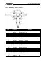
• Snowblower Parts List....................................................................................................20
• Snowblower Gearbox Drawing and Parts List.............................................................23
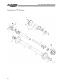
• PTO Drawing...................................................................................................................24
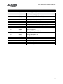
• PTO Parts List..................................................................................................................25
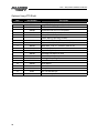
• Optional Long PTO Shaft................................................................................................26
• 1.75 x 5 Cylinder Assembly Drawings and Parts List...................................................27
Optional Kits...............................................................................................................................28
• Hand Crank Spout Rotation...........................................................................................28
• Hydraulic Spout Rotation...............................................................................................30
Shipping Kit and Bundle Numbers...........................................................................................32
Warranty......................................................................................................................................34
Manufacturer’s statement: for technical reasons Buhler Industries Inc. reserves the right to modify
machinery design and specifications provided herein without any preliminary notice.
Information provided herein is of descriptive nature. Performance quality may depend on soil fertility,
applied agricultural techniques, weather conditions and other factors.
3
Introduction - 7420, 8420 & 8420G Snowblower
Introduction
Allied has years of snowblower manufacturing expertise and thousands of acreages, farms and
cities depend on Allied snowblowers.
PTO-driven Allied snowblowers attach to a tractor’s 3-point hitch. This snowblower is supplied with
Category 1 pins with conversion bushings to Category 2 available. The 7420 and 8420 snowblowers
have open gearboxes. The Y8420G has an oil bath gearbox. Adjustable side mounted skid shoes are
standard on all models.
Shear bolt protection is provided at the sprocket to the main auger, and is easily accessed by
removing nuts and cover at the back of the housing.
A hitch system, which is quick-hitch compatible is standard on all models. A longer 36" PTO shaft is
optional.
Options are available for spout rotation and deflector control. Two additional spout rotation options
include hand powered and hydraulic. The deflector may also be controlled by an optional hydraulic
cylinder kit. There is a shear bolt on the auger and on the PTO shaft to protect the machine from
damage if a large object is picked up. Any smaller objects in the snow will be thrown with it and
could cause serious injury. Do not allow anyone to stand behind the tractor or in the area of the
discharged snow.
Keep this manual handy for frequent reference. All new operators or owners must review the
manual before using the equipment and at least annually thereafter. Contact your Allied Dealer if
you need assistance, information, or additional copies of the manual. Visit our website
at www.farm-king.com for a complete list of dealers in your area.
The directions left, right, front and rear, as mentioned throughout this manual, are as seen facing
in the direction of travel of the implement.
4
Safety - 7420, 8420 & 8420G Snowblower
Safety
Safety Instructions
Remember, YOU are the key to safety. Good safety practices not only protect you, but also the
people around you. Make these practices a working part of your safety program. Be certain that
everyone operating this equipment is familiar with the recommended operating and maintenance
procedures and follows all the safety precautions. Most accidents can be prevented. Do not risk
injury or death by ignoring good safety practices.
The alert symbol is used throughout this manual. It indicates attention is required and identifies
hazards. Follow the recommended precautions.
The safety alert symbol means…
ATTENTION! BECOME ALERT! YOUR SAFETY IS INVOLVED!
CAUTION
The caution symbol indicates a potentially hazardous situation
that, if not avoided, may result in minor or moderate injury. It
may also be used to alert against unsafe practices.
WARNING
The Warning Symbol indicates a potentially hazardous situation
that, if not avoided, could result in death or serious injury, and
includes hazards that are exposed when guards are removed. It
may also be used to alert against unsafe practices.
DANGER
The Danger Symbol indicates an imminently hazardous situation
that, if not avoided will result in death or serious injury. This
signal word is to be limited to the most extreme situations,
typically for machine components that, for functional purposes,
cannot be guarded.
5
Safety - 7420, 8420 & 8420G Snowblower
General Safety Instructions
• Have a first-aid kit available for use and know how to use it.
• Have a fire extinguisher available, stored in a highly visible location, and know how to use it.
• Wear appropriate protective gear. This list may include but is not limited to:
-- hard hat
-- protective shoes with slip resistant soles
-- protective glasses or goggles
-- heavy gloves
-- wet weather gear
-- hearing protection
-- respirator or filter mask
• Read and understand the Operator’s Manual and all safety signs before operating, servicing,
adjusting, repairing, or unplugging the equipment.
• Do not attempt any unauthorized modifications to your Farm King product as this could affect
function or safety, and could affect the life of the equipment.
• Never start or operate the snowblower except from the operator’s station on the power unit.
• Inspect and clean the working area before operating.
• Keep hands, feet, clothing, and hair away from moving parts.
• Ensure bystanders are clear of the area before operating.
Start-Up Safety
•
•
•
•
•
•
Do not let inexperienced operators or children run this equipment.
Place all tractor and machine controls in neutral before starting.
Operate only with ROPS and seatbelt equipped tractors.
Do not operate inside a building unless there is adequate ventilation.
Ensure all shields are in place and in good condition before operating.
Stay clear of PTO shaft and machine when engaging PTO.
Operation Safety
•
•
•
•
•
•
•
6
Do not permit riders.
Do not wear loose fitting clothing during operation.
Do not allow anyone other than the operator close to the Auger when in operation.
Stay clear of snowblower augers.
Stay clear of snowblower discharge chute. Rocks or debris can be picked up and thrown.
Never operate over 540 PTO rpm speed.
Never operate equipment in the raised position.
Safety - 7420, 8420 & 8420G Snowblower
Transport Safety
• Review Transport Safety instructions in tractor manual before moving.
• Check with local authorities regarding transport on public roads. Obey all applicable laws
and regulations.
• Make sure the SMV (Slow Moving Vehicle) emblem and all the lights and reflectors that are
required by the local highway and transport authorities are in place, are clean, and can be
seen clearly by all overtaking and oncoming traffic.
• Never have the equipment in operation during transport.
• Always travel at a safe speed.
Service and Maintenance Safety
• Stop engine, set brake, remove ignition key, and wait for all moving parts to stop before
servicing, adjusting, repairing, or unplugging.
• Support the equipment with blocks or safety stands before working beneath it.
• Follow good shop practices including:
-- keep service area clean and dry
-- be sure electrical outlets and tools are properly grounded
-- use adequate light for the job.
• Use only tools, jacks, and hoists of sufficient capacity for the job.
• Replace and secure all shields removed during servicing before operating.
• Use heavy leather gloves to handle sharp objects.
• Check hydraulics regularly for leaks. Use cardboard to look for leaks, and use hand and eye
protection.
• Relieve pressure on hydraulic system before repairing or adjusting.
Storage Safety
• Store the unit in an area away from human activity.
• Do not permit children to play on or around the stored machine.
• Support the frame on stands and blocks to provide a secure base.
7
Safety - 7420, 8420 & 8420G Snowblower
Safety Signs
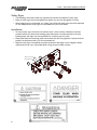
• The following illustration shows the approximate location and detail of safety signs.
• Keep all safety signs clean and legible and replace any that are damaged or missing.
• When original parts are replaced, any safety signs affixed to those parts should be replaced
as well. Replacement safety signs are available from your local dealer.
Installation
• To install safety signs, ensure the installation area is clean and dry. Decide on the exact
position before you remove the backing paper. Remove the smallest portion of the split
backing paper and align over the specified area. Carefully press in place.
• Slowly peel back the remaining paper and smooth the remaining portion in place. Small air
pockets can be pierced with a pin and smoothed out.
• Replace safety signs immediately should they become damaged, torn or illegible. Obtain
replacements from your authorized dealer using the part numbers shown.
Manual Holder
Serial Number
1
3
2
1
8
2
3
Assembly - 7420, 8420 & 8420G Snowblower
Assembly Instructions
1. 740: Turn the bottom tube weldments (907213) as shown in drawing and slide them into the
sleeve welded to the main body.
840 & 840G: Turn the bottom tubes (907250) as shown in drawing and slide them into the
sleeve welded to the main body.
All sizes: The correct position for each individual tractor will be determined when mounting the
snowblower on the tractor. These tubes are connected to the sleeves with a 3/4" x 4-1/4" pin
(816131) and a hair pin clip (961012).
2. 740: Bolt the left (815263) and the right (815264) hitch arms to the inside of the plates welded
to the hitch tubes using 7/8" x 2-1/2" hex bolts (966527) and lock nuts. Join the top of the hitch
arms by bolting a 1" O.D. x 2" spacer (965808) between the top plates using a 3/4" x 4" bolt
(84336), lock washer (81701) and hex nut (81700) through the lower outside holes. Bolt the
upper hitch tube weldment (907218 / 907221) between the same plates using the same size of
bolt. Use the inside holes on the top plates for the upper tube. The other end of the top hitch
tube bolts between the welded brackets on the top edge of the fan housing with the same
hardware. Tube must be turned as shown in drawing. Tighten all hardware.
840 & 840G: Turn the hitch weldments (F0463) as shown in drawing. Bolt the hitch to the two
bottom tubes (907250) using 7/8" x 5" bolts (811826) and lock nuts. The upper hitch tube (907218
/ 907221) bolts to the top of the hitch and the welded brackets on the top edge of the fan
housing using 3/4" x 4" bolts (#84336), lock washers (81701) and hex nuts (81700). Tube must
be turned as shown in drawing. Join the top of the hitch arms by bolting a 1" O.D. x 2" spacer
(965808) between the top plates using a 3/4" x 4" bolt, lock washer and hex nut through the
lower outside holes. Tighten all hardware.
3. 740: A Category 1 top link pin (965807) is fitted in the top holes of the hitch arm plates. This pin
is used for standard three-point hitch only. The bushing in the lower holes is used for the quick
hitch.
840 & 840G: The hitch fits standard Category 1 and 2 three-point hitches as well as Category 1
and 2 quick hitches. The highest and lowest holes are for standard three-point only. The inside
set of holes must be used for a quick hitch. Adaptor bushings are supplied to convert from
Category 1 or 2.
4. Mount the discharge spout (816666) using the spacers and spout clamps (816930 & 815574)
bolted to the spout ring on the snowblower. Lubricate the spout ring and clamps.
5. Reference table of contents for spout rotation information
9
Assembly - 7420, 8420 & 8420G Snowblower
6. Mounting Snowblower on Tractor
-- Mount the snowblower on a tractor with a Category 1 or Category 2 hitch.
-- Using tape or a bright colored marking pen, mark on the outer shields the position where
the shaft is completely pushed together and the position where you have a 4" overlap.
Watch these marks when moving the blower through all possible operating angles to see
that the PTO shaft stays within this range.
-- With the tractor engine shut off, attach the PTO shaft. The tractor end has a standard
6-spline end with a spring loaded locking collar. The snowblower end has a clamp-style
yoke with a 3/8" keyway. Slide the yoke onto the gearbox shaft with the 3/8" key supplied.
Lock the yoke in place with the 1/2" x 3" hex bolt and lock nut fitted through the groove
in the gearbox shaft. After tightening the bolt, insert and tighten the 3/8" socket set screw
supplied.
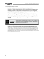
CAUTION
Always check to see that both ends of the PTO shaft are securely
attached every time the snowblower is used. This should always
be done with the tractor engine off.
-- Check that the PTO shaft does not bottom out or separate with the snowblower in the
extreme high and low positions. Check to see which of the four different hitch positions
will allow you to keep about a 4" minimum overlap on the PTO shields without bottoming
out. This position varies between different tractor models because of the different lengths
of the three-point arms. If the PTO shaft is still too long with the hitch fully extended, the
PTO shaft will have to be cut shorter. Check for free movement of all parts in various raised
positions, particularly the PTO shaft.
10
Assembly - 7420, 8420 & 8420G Snowblower
7. PTO Shield:
-- All snowblowers are supplied with a PTO shield. Bolt the shield (965410) to the hinges on
the top of the gearbox on both the 740 and 840 snowblowers using 1/4" x 1/2" hex bolts,
lock washers and hex nuts. Insert a 3/16" cotter pin in the hole in the shield and in the hole
at the bottom corner of the gearbox. Fold back the cotter pins to hold them in place. Hook
the ends of the spring (960135) into these cotter pins to hold the shield down. To mount
the shield (965409) on the 840G snowblower, remove the two rear bolts at the top of the
gearbox (BU50506). Bolt the PTO shield to the gearbox plate using these same bolts. Insert
a 3/16" cotter pin in the hole in the shield and fold to lock in place. Hook one end of the
spring (960135) into this cotter pin and the other end into a hole in the lower gearbox plate
to hold the shield in place.
CAUTION
Do not run the snowblower without this shield in place.
8. Parking Stand:
All snowblowers are supplied with a parking stand. Bolt the parking stand (816255) to the
back of the snowblower body, below the spout. Place a flat washer (84048) between parking
stand and body. Assemble with supplied hardware, (84048, 81966, 87553, 816268). Do not over
tighten the lock nut so that the parking stand can rotate freely. Insert detent pin (816268) into
the top hole of parking stand.
11
Operation - 7420, 8420 & 8420G Snowblower
Operation Instructions
1. Do not operate the snowblower in the fully raised position. The 3-point hitch on some tractors
raises high enough to cause the PTO shaft to bind. This can cause damage to the PTO shaft
and/or to the hitch and pins. NOTE: PTO shaft angle should not exceed 20° for optimum
performance and life. Damage may occur to PTO and/or snowblower if angle becomes more
extreme.
2. Depth of cut can be partially controlled by tilting the blower forward or backward. Adjust the
top link of the tractor hitch so the snowblower is just slightly tilted back when resting on the
ground.
ALERT
Excessive backward tilt may cause the “U” joints to flutter
resulting in PTO shear bolt failure.
3. Adjust the lower link sway chains or blocks on the tractor to restrict side movement of the
snowblower when operating.
4. Run the snowblower at low rpm to check operation before blowing snow.
5. The snowblower has two shear bolts to protect the tractor and snowblower in case a large
object enters the blower. PTO shear bolt (Two 5/16" x 1"- Grade 5) Auger shear bolt (1/4" x 1"Grade 5). Shear bolts should be fastened with a lock nut or two jam nuts. These bolts must be
kept tight to prevent wear of the bolt and bolt holes.
6. Never run PTO shaft over 540 rpm.
7. Chain Tension: Slack on the lower side of the chain should be 3/8" to 1/2"
8. Lubrication:
-- The spout clamps and rings should be periodically lubricated with lithium general
purpose grease.
-- PTO shaft universal joints and square shaft slide should be greased daily.
-- Regularly oiling the chain will significantly increase the life of the chain.
-- The grease fitting on the hydraulic spout swivel arm should be kept lubricated.
-- 740 & 840 only: Gearbox is open type and need not be greased
840G only: See Section on refilling for correct oil level. Use any 80-90 gear oil or
multigrade with 80 minimum.
9. Periodically check all bolts for tightness. The bolt holding on the fan and the bearing bolts are
of particular importance.
DANGER
12
Always stop snowblower for servicing or unplugging. The PTO
should be disengaged before dismounting from the tractor.
Operation - 7420, 8420 & 8420G Snowblower
CAUTION
Always check to see that both ends of the PTO shaft are securely
attached as per instructions every time you are preparing to use
the snowblower.
10. When replacing bearings or tightening a loose bearing collar, always tighten collar in the
direction of shaft rotation using a center punch or a similar tool.
11. Shear Sprocket: The shear sprocket (965826) should be checked at the beginning of every
season to make sure it will spin freely. With time the sprocket plate could corrode and seize
which will not allow the shear bolt to break if something jams in the snowblower auger. Clean
to loosen if necessary.
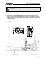
Theory of Operation
Fan Blade Rotation
Spout Rotation
13
Maintenance - 7420, 8420 & 8420G Snowblower
Maintenance
Refilling 840G Gearbox with Oil
• If the gearbox requires refilling with oil because of repairs to the gearbox, add oil to the level
shown in the drawing.
• Check the level regularly using the plug in the lid.
• The correct level is even with the bottom of the plug.
14
Bolt Torque - 7420, 8420 & 8420G Snowblower
Bolt Torque
Checking Bolt Torque
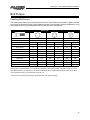
The tables shown below give correct torque values for various bolts and hex bolts. Tighten all bolts
to the torques specified in chart unless otherwise noted. Check tightness of bolts periodically, using
bolt torque chart as a guide. Replace hardware with the same strength bolt.
Bolt Torque*
Bolt Diameter
Grade 2 Bolts
Grade 5 Bolts
Grade 8 Bolts
(inches)
SAE 2
SAE 5
SAE 8
“A”
(lb-ft)
(N.m)
(lb-ft)
(N.m)
(lb-ft)
(N.m)
0.25 (1/4)
6
8
9
12
12
17
0.313 (5/16)
10
13
19
25
27
36
0.375 (3/8)
20
27
33
45
45
63
0.438 (7/16)
30
42
53
72
75
100
0.5 (1/2)
45
61
80
110
115
155
0.563 (9/16)
70
95
115
155
165
220
0.625 (5/8)
95
128
160
215
220
305
.75 (3/4)
165
225
290
390
400
540
0.875 (7/8)
170
230
420
570
650
880
1
225
345
630
850
970
1320
Torque figures indicated above are valid for non-greased or non-oiled threads and heads unless otherwise
specified. Therefore, do not grease or oil bolts or hex bolts unless otherwise specified in this manual. When
using locking elements, increase torque values by 5%.
* Torque value for bolts and hex bolts are identified by their head markings.
15
Bolt Torque - 7420, 8420 & 8420G Snowblower
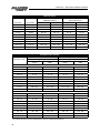
Hydraulic Fittings
Jam Nut or Straight
ORB Fitting Torque
SAE 37° (JIC)
Swivel Nut Torque
Dash Size
Thread Size
(lbs-ft)
(NM)
(lbs-ft)
(NM)
-4 (1/4)
7/16-20
16 - 14
20 - 22
11 - 10
13 - 15
-5 (5/16)
1/2-20
20 -18
24 - 27
15 - 13
18 - 20
-6 (3/8)
9/16-18
26 - 24
33 - 35
19 - 17
23 - 26
-8 (1/2)
3/4-16
60 - 50
68 - 78
38 - 34
47 - 52
-10 (5/8)
7/8-14
80 - 72
98 - 110
56 - 50
69 - 76
-12 (3/4)
1-1/16-12
135 - 125
170 - 183
78 - 70
96 - 106
-14 (7/8)
1-3/16-12
180 - 160
215 - 245
90 - 80
110 - 122
-16 (1)
1-5/16-12
220 - 200
270 - 300
104 - 94
127 - 141
-20 (1 1/4)
1-5/8-12
280 - 210
285 - 380
138 - 124
169 - 188
-24 (1 1/2)
1-7/8-12
360 - 270
370 - 490
173 - 156
212 - 235
Prevailing Torque Lock Nuts
Nut Size and
Threads per Inch
Grade B Nuts
Grade C Nuts
Nut Tightening Torque
Nut Tightening Torque
(lbs-ft)
(NM)
(lbs-ft)
(NM)
10 - 7
9 - 14
Coarse Thread
1/4 - 20
7-5
7-9
3/16 - 18
12.5 - 9
12 - 17
16 - 11
15 - 22
3/8 - 16
20 - 14.5
20 - 27
28 - 20
27 - 38
7/16 - 14
32 - 23
31 - 43
43 - 31
42 - 58
1/2 - 13
50 -37
50 - 68
62.5 - 45
61 - 85
9/16 - 12
70 - 50
68 - 95
95 - 70
95 - 129
5/8 - 11
95 - 70
95 - 129
122.5 - 90
122 - 166
3/4 - 10
165 - 125
169 - 224
210 - 155
210 - 285
7/8 - 9
250 - 185
251 - 339
312.5 - 225
305 - 423
1-8
375 - 275
373 - 508
462.5 - 360
488 - 627
10 -7
9 - 14
Fine Thread
1/4 - 28
7.5 / 5.5
7 - 10
3/16 - 24
13 - 10
14 - 18
17 - 12
16 - 23
3/8 - 24
22 - 16
22 - 30
29 - 21
28 - 39
7/16 - 20
34 - 24
33 - 46
43 - 31
42 - 58
1/2 - 20
52.5 - 37.5
51 - 71
70 - 50
68 - 95
9/16 - 18
77.5 - 57.5
78 - 105
95 - 70
95 - 129
5/8 - 18
97.5 - 72.5
98 - 132
125 - 90
122 - 169
3/4 - 16
165 - 120
163 - 224
210 - 155
210 - 285
7/8 - 14
270 - 200
271 - 266
312.5 - 225
305 - 423
1 - 14
400 - 300
407 - 542
500 - 362.5
491 - 678
1) For Grade A locknut torque specifications refer to Grade B specifications.
16
59
14
16
34
47
62
61
33
5
37
20
15
59
16
34
47
75
36
76
6
8
7
67
8
6
7
72
57
45
52
26
29
30
15
51
10
15
56
93
14
69
70
62
71
84
26
26
48
23
90
77
73
83
50
31
85
63
15
56
25
66
34
18
22
26
58
23
74
24
14
64
71
60
23
73
23
22
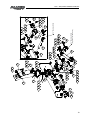
Parts - 7420, 8420 & 8420G Snowblower
7420 & 8420 Snowblower Drawings
17
Parts - 7420, 8420 & 8420G Snowblower
8420G Snowblower Drawings
Check Oil Level
Decal
95
23
50
96
20
18
23
95
30
35
38
3
9
9
99
98
94
12
13
42
1
16
11
98
17
86
98
82
97
41
49
44
39
7
43
7
53
92
89
44
46
81
79
8
8
32
40
28
32
27
16
78
28
27
39
65
88
28
55
87
55
32
3
28
32
19
27
27
28
74" Models Hitch
32
28
84" Models Hitch
(Optional 74" Models)
27
54
40
27
43
32
54
68
55
4
65
Parts - 7420, 8420 & 8420G Snowblower
19
Parts - 7420, 8420 & 8420G Snowblower
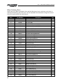
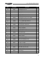
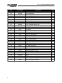
When Ordering Parts
Always give your dealer the Model, Color and Serial Number of your machine to assist them in
ordering and obtaining the correct parts. Use the exploded view and tabular listing of the area of
interest to exactly identify the required part.
20
Item
Part Number
1
811792
Bolt Hex 0.375 x 1.50
Description
Qty
8
2
812363
Nut Lock (Steel) 0.375 Grb Pl
8
3
815263
74" Hitch LHS
1
4
815264
74" Hitch RHS
1
5
81527
Bolt Hex 0.25Nc x 1.00 Gr5 Pl
1
6
81549
Bolt Hex 0.313Nc x 0.75 Gr5 Pl
4
7
81568
5/16" Hex Nut Pl
10
8
81569
5/16" Lock Washer Pl
10
9
81570
Washer 0.375 Flat St Hs Pl
16
10
816977
74" Main Housing Weldment
1
816978
84" Main Housing Weldment
1
816980
84G Main Housing Weldment
1
11
816666
74"/84" Spout Weldment
1
12
816930
74"/84" Spout Spacer
4
13
815574
74"/84" Spout Clamp
4
14
81592
3/8" Hex Nut (Pl)
20
15
81593
Lock Washer 0.375
16
16
816131
3/4" Dia. x 4.25" Lg Clev Pin
2
17
816255
74/84 Parking Stand
1
18
816137
74/84 Fan Shaft
1
19
816151
Clevis Pin 0.88" Dia. x 3-3/4" Lg
2
20
816169
74" Driveshaft Weldment
1
816171
84" Driveshaft Weldment
1
965403
84G Driveshaft Weldment
1
21
81620
Bolt Hex 0.500Nc x 1.25 Gr5 Pl
8
22
81636
1/2" Hex Nut (Pl)
8
23
81637
0.50 Lock Washer
8
24
81676
5/8" Hex Nut (Pl)
1
25
81677
Washer Lock 0.625 Pl
1
26
81678
5/8" Flat Washer Std (Pl)
4
27
81700
3/4" Hex Nut (Pl)
3
28
81701
3/4" Lock Washer (Pl)
3
29
84072
3/8" x 3/4" Hex Bolt (Pl)
4
30
84268
Bolt Hex 0.625Nc x 1.50 Gr5 Pl
5
31
84289
5/8" x 3" Hex Bolt (Pl)
1
32
84336
3/4" x 4" Hex Bolt (Pl)
3
Parts - 7420, 8420 & 8420G Snowblower
Item
Part Number
33
84498
Description
Qty
1/4" Lock Nut (Pl)
1
34
86170
Hex Bolt 0.375 Unc x 1.0
12
35
812639
Washer Flat 0.625
4
36
901939
Aug Assy 74"
1
901934
Aug Assy 84"
1
901940
Dr Shft Key 5/16" x 5/16" x 1-1/4"
1
37
38
816819
Skid Shoe Weldment
2
39
907213
Btm Tube Weldt
2
907250
Htch Tube 3/16" x 2-1/2" x 2-1/2" x 20 5/8"
2
907217
Upr Htch Tube - Cat 1 Hitch
1
907220
Upr Htch Tube - Cat 1 & 2
1
41
816268
1/2" x 1" (Usable Length) Detent Pin
1
40
42
816673
Spout Ring Gear
1
43
907674
7/8" Lock Nut
2
44
812026
Bolt Hex 0.313Nc x 1.00 Gr5 (Pl)
6
45
909277
Manual Holder 3-1/2" x 12"
1
46
961012
#16 Hair Pin Clip
2
47
961637
Bearing Flange 62Ms
4
48
961675
Bearing Flange 72Ms
4
49
961876
1/2" x 1 1/2" Clev Pin (Pl)
2
50
965410
PTO Shld 14Ga
1
965409
84G PTO Shld 14Ga
1
51
965415
Dr Shft Guard 16Ga x 8" x 32"
1
965404
Dr Shft Guard 16Ga x 8" x 37"
1
52
965447
4-Blade Fan Weldt
1
53
965646
1/2" x 1-1/4" x 18" Adj Bar
1
54
965807
Top Link Pin (Cat.1), 5'Rc
1
55
965808
Top Link Pin Bushing Cat 1 & 2
2
56
965814
3/8" x 3/8" x 4-1/4" Fan Shft Key
1
57
965816
Bev Gear 1-1/4" Bore
1
58
965817
Bev Gear 1-1/2" Bore
1
59
965818
Bearing 1-1/4" w/Collar
2
60
965821
3/8" x 3/8" x 1-3/4" Fan Shft Key
1
61
965826
Shear Sprocket 13T #50 1-1/4" Bore
1
62
965827
Rchain #50 x 98 Link w/ Conn
1
63
965834
Idler Spacer 7/64" W x 27/32" Od x 5/8"
1
64
965844
Idler Sprkt 15T #50
1
65
965911
7/16" Linch Pin
1
66
965917
1 3/8" Bearing
2
67
965968
14Ga x 7-1/2" x 8" Idler Shld
1
21
Parts - 7420, 8420 & 8420G Snowblower
22
Item
Part Number
68
966527
Description
7/8" x 2-1/2" Hex Bolt (Pl)
Qty
2
69
9812410
3/8" Lock Washer
4
70
9812356
Bolt Hex 3/8" Nc 1.25 Gr 5 Br
4
71
967260
1-1/2"Ø Brg Flg
4
72
967458
Adma PTO Safety Manual
1
73
968627
1-1/2" Brg w/ Collar
2
74
9812433
3/16" x 1-1/2" Cotter Pin
2
75
9812440
1-1/4" x 18Ga Nr Washer (Br)
1
76
9812442
1-1/4" x 10Ga Nr Washer (Br)
1
77
9812445
1-1/2" x 10Ga Narrow Rim Wash (Br)
2
78
F0463
Hitch Weldt - Cat 1 & 2
1
79
F842
PTO Shaft
1
81
811826
7/8" x 5" Hex Bolt (Pl)
2
82
812364
Nut Lock (Steel) 0.500Nc Grb Pl
1
83
81523
1/4" x 1/2" Hex Bolt (Pl)
2
84
81544
1/4" Hex Nut (Pl)
2
85
81545
1/4" Lock Washer (Pl)
2
86
81627
1/2" x 3" Hex Bolt (Pl)
1
87
907315
Pin Weldt 0.88" x 7.75" Cat 1 & 2
2
88
907316
Pin Sleeve 7/64" W x 1-1/8" x 2-7/8"
2
89
910426
Safety Chain - All
1
90
960135
PTO Shld Sprg (#661)
1
91
909021
Extra Shear Bolt 0.25" Nc Gr5 WINut2
1
92
907590
Spout Hose Holder
1
93
965825
Sprocket 40t #50 1.375" B
1
94
988999
3/8"Ø x 3/8" Socket Set Screw (Br)
1
95
81619
Bolt Hex 0.500 x 1.00 Gr5 Pl
8
96
BU50506
Gbox
1
97
87553
Bolt Hex 0.500 x 1.75 Gr5 (Pl)
1
98
84048
Washer 0.500 Flat SAE Bs Pl
3
99
81966
Nut Lock (Nylon) 0.500Nc Pl
1
Parts - 7420, 8420 & 8420G Snowblower
8420G Snowblower Gearbox Drawing
Item
Part Number
Description
BU50506
Gearbox Complete
1
BU50310
Gearbox Casting Only
2
BU500089-3
3
BU50457
4
BU500167-1
5
BU50458
Gearbox Gasket
6
BU50508
Cross Shaft
7
BU50502
Pinion Shaft
8
BU50329
Bevel Gear - 1-1/2" Bore
Pipe Plug
Gearbox Cover
Relief Valve
9
BU50331
Bevel Gear - 1-3/8" Bore
10
BU50428
Staking Lock Nut
11
BU50444
Staking Lock Nut
12
BU50422-1
Oil Seal (3 Used)
13
BU50415
Retainer Ring (4 Used)
14
BU575902
Bearing Cup (2 Used)
15
BU575901
Bearing Cone (2 Used)
16
BU50429
Key
17
BU50210X
Shim Set
18
BU575907
Bearing Cup (2 Used)
19
BU575906
Bearing Cone (2 Used)
20
BU278811
Retainer Ring
21
BU50417-1
Key
23
Parts - 7420, 8420 & 8420G Snowblower
Snowblower PTO Drawing
24
Parts - 7420, 8420 & 8420G Snowblower
Item
Part Number
F842
Description
Standard PTO Shaft Complete
936263
Tractor Half of PTO (Shear)
936264
Implement Half of PTO (Clamp Yoke)
1
936277
Shear Assembly
2
936199
Safety Slide Lock Repair Kit
3
936249
(Collar, Spring, Ret. Ring, 2-Pawls)
Shear Assembly Repair Kit (3/8" x 1/2" Bolt,
Lube, Blank, 31 - 1/4" Balls)
4
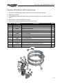
903296
5
6
Shear Bolt - 5/16" x 1" (Grade 5) (Pack of 10)
5/16" Lock Nut
936025
Repair Kit (Option)
906504
Extended Life Repair Kit (Std)
7
936270
Yoke & Tube
8
936319
Bearing & Snap Ring Kit
9
936272
Inner Shield
10
936273
Outer Shield
11
936274
Yoke & Shaft
12
936269
Clamp Yoke
13
1/2" x 3" Hex Bolt (pl)
14
1/2" Lock Nut (pl)
25
Parts - 7420, 8420 & 8420G Snowblower
Optional Long PTO Shaft
Item
Part Number
F844
Description
Long PTO Shaft Complete (Optional)
936285
Tractor Half of PTO (Shear)
936280
Implement Half of PTO (Clamp Yoke)
1
936277
Shear Assembly
2
936199
Safety Slide Lock Repair Kit
3
936249
(Collar, Spring, Ret. Ring, 2-Pawls)
Shear Assembly Repair Kit
(3/8" x 1/2" Bolt, Lube, Blank, 31-1/4" Balls)
26
4
903296
Shear Bolt - 5/16" x 1" (Grade 5) (Pack of 10)
5
812362
5/16" Lock Nut
6
936025
Repair Kit (Option)
906504
Extended Life Repair Kit (Std)
7
936281
Yoke & Tube
8
936319
Bearing & Snap Ring Kit
9
936282
Inner Shield
10
936283
Outer Shield
11
936284
Yoke & Shaft
12
936269
Clamp Yoke
13
81627
1/2" x 3" Hex Bolt (pl)
14
812364
1/2" Lock Nut (pl)
Parts - 7420, 8420 & 8420G Snowblower
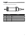
1.75 x 5 Cylinder Assembly Drawing (Optional)
Item
Part Number
24930M
-
Description
Cylinder Complete
X3913
Seal Kit
F9117
Spout Deflector Cylinder & Hose Kit
1
116984
Hose 3/8 x 120 c/w Fittings
2
24930M
Cylinder 1.75 Dia x 5.0 9/16 Orb
3
960913
Clevis Pin 0.500 x 1.813 Pl
4
9812430
Cotter Pin 0.125 x 1.00 Pl
27
Optional Kits - 7420, 8420 & 8420G Snowblower
Optional Kits
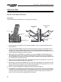
Hand Crank Spout Rotation
Assembly
Use picture below or exploded view on next page for reference
Open Gearbox
Models
Closed Gearbox
Models
Hand Crank Unit
Correct Ring Gear
Orientation
Empty Holes
Empty Holes
Use these holes
Use these holes
P-Clamps for use with
Hydraulic Deflector Control
Empty hole
1. Bolt horizontal brace (816893) to crank bracket (816895) using the supplied hardware (81570,
81344, & 86171).
2. Insert crank handle (816896) into taller end of crank bracket. Insert gear onto handle with hub
towards end. Finish inserting handle onto the other end of crank bracket. Bolt on gear with
supplied 1/4" hardware (81531 & 81922). Place 1" washer (84522) onto end of handle then insert
roll pin (9812425) through hole closest to the end.
3. Rotate gear spout ring (816673) on the bottom of the spout (816666) if needed. With spout in
forward facing position, the non-toothed smooth portion of the gear spout ring should be on
the side opposite of the gear on the hand crank. Make sure bolts come through the bottom and
the washer and nut are located on top.
4. Bolt crank onto snowblower body with supplied hardware (81570, 81344, 86171). Turn chute or
handle manually to obtain alignment of gear teeth.
5. When bolting vertical brace (816894) onto unit, the holes used depends on snowblower model.
Start by bolting on the lower part. This will help correctly identify which top hole to use. Finish
bolting on brace with supplied hardware (81570, 81344, 86171)
6. Bolt on side brace (816993) with supplied hardware (81570, 81344, 86171).
7. If snowblower is equipped with the optional hydraulic chute control, insert hoses into P-clamps
(815250) then bolt onto crank bracket. Carefully operate the chute to full left and right positions
to ensure hoses have sufficient slack to not prohibit movement. Keep slack to a minimum to
prevent hoses from becoming trapped between the gears.
28
Optional Kits - 7420, 8420 & 8420G Snowblower
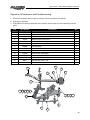
Operation, Maintenance and Troubleshooting
1. Ensure all hardware remains tight or function of unit may become impaired.
2. Keep gears lubicated.
3. If equipped with optional hydraulic chute control, ensure hoses are not interfering with the
gears.
Item
Part Number
1
81344
Lock Nut (Nylon) 0.375 Nc
Description
Qty
9
2
815250
P-Clamp For 3/4 Od, .406 Hole
2
3
81531
Bolt Hex 0.25 Nc x 2.00 Gr5 Pl
1
4
81570
Washer 0.375 Flat St Hs Pl
17
5
816893
Hortizonal Brace
1
6
816894
Vertical Brace
1
7
816895
Crank Bracket
1
8
816896
Crank Handle
1
9
816897
Gear Weldment
1
10
816993
Hand Crank - Side Brace
1
11
81922
Lock Nut (Nylon) 0.25 Nc
1
12
84522
Washer Flat 1.00
1
13
86171
Bolt Hex 0.375 Nc x 1.25
9
14
9812425
1/4" x 1-1/4" Spring Pin
1
14
8
12
3
9
11
10
1
2
4
2
13
13
7
4
4
1
5
2
6
29
Optional Kits - 7420, 8420 & 8420G Snowblower
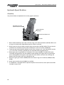
Hydraulic Spout Rotation
Assembly
Use picture below or exploded view on next page for reference
Hose Holder for use with
Hydraulic Deflector Control
Correct Ring Gear
Orientation
Hydraulic Spout Rotation Unit
Hose Parts
1. Bolt manifold (816919) to the motor (971518) using 5/16" socket head bolts (967249). Make sure
o-rings are in place after disposable protective shield is removed.
2. Mount motor to the main body using 3/8" bolts and washers (86170 & 81593). Ensure that the
manifold is on the side that points the manifold ports to the rear of the snowblower.
3. Fasten the gear hub weldment (816435) to the motor using the 1/4" x 3/4" bolt (81525) and the
1-1/2" OD x 5/16" ID washer (813748) with the extended hub facing downwards.
4. Rotate gear spout ring (816673) on the bottom of the spout (816666) if needed. With spout
in forward facing position, the non-toothed smooth portion of the gear spout ring should be
on the side opposite of the gear on the hydraulic motor. Make sure bolts come through the
bottom and the washer and nut are located on top.
5. Secure the gear guard cover (816840) above the motor using 5/16" hardware (812026, 81569,
81568).
6. Attach spout rotation hoses (816682) to manifold.
7. If snowblower is equipped with the optional hydraulic chute control, install spout hose holder
included in spout crate.
30
Optional Kits - 7420, 8420 & 8420G Snowblower
Operation, Maintenance and Troubleshooting
1. Ensure all hardware remains tight or function of unit may become impaired.
2. Keep gears greased.
3. If equipped with optional hydraulic chute control ensure hoses are not interfering with the
gears.
4. Ensure proper hydraulic fluid level in tractor.
5. Gear cover must be installed before operation of the spout
Item
Part Number
Description
Qty
1
816435
Gear Hub Weldt
1
2
971518
Hydraulic Motor 101-1018-009
1
3
816919
Manifold - Spt Gear Rot
1
4
813748
Washer, Fender, 1-1/2" Od x 5/16" Id (Pl)
1
5
81525
Bolt Hex 0.250Nc x 0.750 Gr5 Pl
1
6
816840
Gear Guard Weldt
1
7
812026
5/16" x 1" Hex Bolt (Pl)
2
8
81568
5/16" Hex Nut (Pl)
2
9
81569
5/16" Lock Washer Pl
2
10
86170
Hex Bolt 0.375 Unc x 1.0
4
11
81593
Lock Washer 0.375
4
12
812208
Nipple 1/2" Body 1/2"-14 Nptf Quick Connect
2
13
816677
Hose 3/8 x 92 1/2 Mnpt x 3/4 Morb
2
14
967249
5/16" x 2" Sckt Head Bolt (Br)
4
12
6
7
5
9
4
8
1
2
10
13
3
11
14
31
Parts - 7420, 8420 & 8420G Snowblower
Shipping Kit and Bundle Numbers
The following is a list of Kit Numbers for this product and the Bundle Numbers, Descriptions, and
Quantities for each Kit.
Quantity
Bundle Number
Description
YC7420 - 74" Snowblower w/ Hydraulic Chute Control, 4-Blade Fan
1
F1663A
Body Assembly
YC8420 - 84" Snowblower w/ Hydraulic Chute Control, 4-Blade Fan
1
F1664A
Body Assembly
1
F0463
Hitch
YC8420G - 84" Snowblower w/ Hydraulic Chute Control, 4-Blade Fan
1
F1665A
Body Assembly
1
F0463
Hitch
Optional Bundle Numbers
The following is a list of options available for the Kits listed above.
1
F844
36" Optional Long PTO
1
F842
Standard PTO
1
F9117
Spout Deflector Cylinder & Hose Kit
1
F1545
Hydraulic Spout Rotation (Optional)
1
F1658
Hand Crank Spout Rotation (Optional)
32
Warranty - 7420, 8420 & 8420G Snowblower
Allied by Farm King Limited Warranty
This document limits your warranty rights.
Base Limited Warranty
Buhler Industries Inc. provides this warranty only to original retail purchasers of its product.
Buhler Industries Inc. warrants to such purchasers that all Buhler Industries Inc. manufactured
parts and components used and serviced as provided for in the Operator’s Manual shall be free
from defects in materials and workmanship for a period following delivery to the original retail
purchaser of 12 months (80 days for commercial applications). This limited warranty applies only
to those parts and components manufactured by Buhler Industries Inc. Parts and components
manufactured by others are subject to their manufacturer’s warranties, if any.
Buhler Industries Inc. will fulfill this limited warranty by, at its option, repairing or replacing
any covered part that is defective or is the result of improper workmanship, provided that the
part is returned to Buhler Industries Inc. within thirty (30) days of the date that such defect or
improper workmanship is, or should have been, discovered. Buhler Industries Inc. reserves the
right to either inspect the product at the buyer’s location or have it returned to the factory for
inspection. Parts must be returned through the selling representative and the buyer must prepay
transportation charges.
Buhler Industries Inc. will not be responsible for repairs or replacements that are necessitated,
in whole or part, by the use of parts not manufactured by or obtained from Buhler Industries Inc.
Under no circumstances are component parts warranted against normal wear and tear. There
is no warranty on product pump seals, product pump bearings, rubber product hoses, pressure
gauges, or other components that require replacement as part of normal maintenance. Also:
Buckets and Bucket Tines carry no warranty, Bent Spears carry no warranty, Snowblower Fan
Shafts carry no warranty, Mower Blades carry no warranty, Portable Auger Parts Have Two (2)
Year Warranty, Loader Parts Have Two (2) Year Warranty. The purchaser is solely responsible for
determining suitability of goods sold. This warranty is expressly in lieu of all other warranties
expressed or implied. Buhler Industries Inc. will in no event be liable for any incidental or
consequential damages whatsoever. Nor for any sum in excess of the price received for the
goods for which liability is claimed.
Repair Parts Limited Warranty
Buhler Industries Inc. warrants Farm King replacement parts purchased after the expiration of the
Buhler Industries Inc. Limited Warranty, and used and serviced as provided for in the Operator’s
Manual, to be free from defects in materials or workmanship for a period of thirty (30) days
from the invoice date for the parts. Buhler Industries Inc. will fulfill this limited warranty by, at
its option, repairing or replacing any covered part that is defective or is the result of improper
workmanship, provided that the part is returned to Buhler Industries Inc. within thirty (30) days
of the date that such defect or improper workmanship is, or should have been, discovered. Such
parts must be shipped to Buhler Industries Inc. at the purchaser’s expense.
What is Not Covered
Under no circumstances does this limited warranty cover any components or parts that have
been subject to the following: negligence; alteration or modification not approved by Buhler
Industries Inc.; misuse; improper storage; lack of reasonable and proper maintenance, service,
or repair; normal wear; damage from failure to follow operating instructions; accident; and/
or repairs that have been made with parts other than those manufactured, supplied, and or
authorized by Buhler Industries Inc.
34
Warranty - 7420, 8420 & 8420G Snowblower
Authorized Dealer and Labor Costs
Repairs eligible for labor under this limited warranty must be made by Buhler Industries Inc. or an
authorized Farm King dealer. Buhler Industries Inc. retains the exclusive discretion to determine
whether it will pay labor costs for warranty repairs or replacements, and the amount of such
costs that it will pay and the time in which the repairs will be made. If Buhler Industries Inc.
determines that it will pay labor costs for warranty work, it will do so by issuing a credit to the
dealer’s or distributor’s account. Buhler Industries Inc. will not approve or pay invoices sent for
repairs that Buhler Industries Inc. has not previously approved. Warranty service does not extend
the original term of this limited warranty.
Warranty Requirements
To be covered by warranty, each Farm King new product must be registered with Buhler
Industries Inc. within thirty (30) days of delivery to original retail purchaser. If the customer
decides to purchase replacement components before the warranty disposition of such
components is determined, Buhler Industries Inc. will bill the customer for such components and
then credit the replacement invoice for those components later determined to be covered by this
limited warranty. Any such replacement components that are determined not be covered by this
limited warranty will be subject to the terms of the invoice and shall be paid for by the purchaser.
Warranty Claims:
Warranty requests must be prepared on Buhler Industries Inc. Warranty Claim Forms with all
requested information properly completed. Warranty Claims must be submitted within a thirty
(30) day period from date of failure repair.
Warranty Labor:
Any labor subject to warranty must be authorized by Buhler Industries Inc. The labor rate for
replacing defective parts, where applicable, will be credited at 100% of the dealer’s posted shop
rate.
Exclusive Effect of Warranty and Limitation of Liability
TO THE EXTENT PERMITTED BY LAW, BUHLER INDUSTRIES INC. DISCLAIMS ANY
WARRANTIES, REPRESENTATIONS, OR PROMISES, EXPRESS OR IMPLIED, AS TO THE QUALITY,
PERFORMANCE, OR FREEDOM FROM DEFECT OF THE COMPONENTS AND PARTS COVERED BY
THIS WARRANTY AND NOT SPECIFICALLY PROVIDED FOR HEREIN.
TO THE EXTENT PERMITTED BY LAW, BUHLER INDUSTRIES INC. DISCLAIMS ANY IMPLIED
WARRANTIES OF MERCHANTABILITY AND FITNESS FOR A PARTICULAR PURPOSE ON ITS
PRODUCTS COVERED HEREIN, AND DISCLAIMS ANY RELIANCE BY THE PURCHASER ON
BUHLER INDUSTRIES INC.’S SKILL OR JUDGMENT TO SELECT OR FURNISH GOODS FOR ANY
PARTICULAR PURPOSE. THE PURCHASER’S ONLY AND EXCLUSIVE REMEDIES IN CONNECTION
WITH THE BREACH OR PERFORMANCE OF ANY WARRANTY ON PRODUCTS MANUFACTURED
BY BUHLER INDUSTRIES INC. ARE THOSE SET FORTH HEREIN. IN NO EVENT SHALL BUHLER
INDUSTRIES INC. BE LIABLE FOR INCIDENTAL OR CONSEQUENTIAL DAMAGES (INCLUDING,
BY WAY OF EXAMPLE ONLY AND NOT LIMITATION, LOSS OF CROPS, LOSS OF PROFITS OR
REVENUE, OTHER COMMERCIAL LOSSES, INCONVENIENCE, OR COST OF REPLACEMENT
OF RENTAL EQUIPMENT). IN NO EVENT SHALL FARM KING’S CONTRACT OR WARRANTY
LIABILITY EXCEED THE PURCHASE PRICE OF THE PRODUCT.
35
Warranty - 7420, 8420 & 8420G Snowblower
(Note that some provinces or states do not allow limitations on how long an implied warranty
lasts or the exclusion or limitation of incidental or consequential damages, so the above
limitations and exclusion may not apply to you.) This warranty gives you specific legal rights and
you may also have other rights, which vary from province to province or state to state.
Buhler Industries Inc. neither assumes nor authorizes any person or entity, including its selling
representatives, to assume any other obligations or liability in connections with the sale of
covered equipment, or to make any other warranties, representations, or promises, express or
implied, as to the quality, performance, or freedom from defect of the components and parts
covered herein. No one is authorized to alter, modify, or enlarge this limited warranty, or its
exclusions, limitations and reservations.
Corrections of defects and improper workmanship in the manner, and for the applicable time
periods, provided for herein shall constitute fulfillment of all responsibilities of Buhler Industries
Inc. to the purchaser, and Buhler Industries Inc. shall not be liable in negligence, contract, or on
any other basis with respect to the subject equipment.
This limited warranty is subject to any existing conditions of supply which may directly affect
Buhler Industries Inc.’s ability to obtain materials or manufacture replacement parts.
Buhler Industries Inc. reserves the right to make improvements in design or changes in
specifications to its products at anytime, without incurring any obligation to owners of units
previously sold.
Government Legislation:
Warranty terms and conditions are subject to provincial or state legislation.
Important Note: This warranty does not apply to rentals.
36
www.farm-king.com
1330 43rd Street NW
Fargo, ND USA 58102
Ph.: 701.282.7014 | Fax: 701.282.5865
Toll Free: 888.524.1004
E-mail: [email protected]
www.farm-king.com
Equipment shown is subject to change without notice.
©2014 Buhler Trading Inc. Printed in USA. TSX:BUI
a division of Buhler Industries Inc.