1
8965, 8968, 8975, and 8985 Access Cards
Installation Instructions
Document Number 8900-A2-ZZ40-50
December 2005
Contents
End User License Agreement (Zhone and Affiliates) ................................
1
Access Cards ............................................................................................
3
Product Documentation Online .................................................................
4
Installation Overview .................................................................................
4
Cables You Need .......................................................................................
5
Installing the Cards in a BLC .....................................................................
6
Connecting to the ATM or IP Network .......................................................
7
Connecting 24-Port Models to an MDF or POTS Splitter ..........................
7
Connecting 48-Port Models to an MDF or POTS Splitter .......................... 11
Front Panel LEDs (Models 8965, 8975, and 8985) ................................... 14
Front Panel LEDs (Model 8968) ................................................................ 16
Logging In to the BLC ............................................................................... 17
Configuration ............................................................................................. 18
Contacting Global Service and Support .................................................... 19
Technical Support ...................................................................................... 19
Service Requirements ............................................................................... 19
Trademarks ............................................................................................... 19
End User License Agreement (Zhone and Affiliates)
Do not install this Software unless you agree to these provisions.
Return the Software promptly for a refund if you do not agree.
License. Zhone Technologies, Inc. and/or an affiliate ("Zhone") hereby grants
you ("User")—either an individual or a single business entity—the
non-exclusive right to install, access, run, or interact with ("Use") one copy of
the enclosed software (which may have been, or may be, provided on media,
as part of a hardware platform, through download, or otherwise) and
associated documentation ("Software") on the first computer system on which
Zhone Technologies
@Zhone Way
7001 Oakport Street
Oakland, CA 94621
USA
Copyright © 2005
Zhone Technologies, Inc.
1
.
User installs the Software ("System") solely for internal business purposes
(including, without limitation, providing products and services to User's
customers) and subject to the restrictions below). Zhone may, in its sole
discretion, make available future updates or upgrades to the Software each of
which is also Software subject hereto. Title to and all patent rights, copyrights
and other intellectual property rights in the Software are retained by Zhone
and its direct and indirect suppliers and licensors ("Licensors").
Restrictions. The Software may not be (a) Used on or from any system other
than the System; (b) Used with more than any maximum number of
subscribers stated in the documentation accompanying the Software; (c) Used
so as to circumvent any technological measure included therein or provided
by Zhone from time to time to control access to or limit use of the Software;
(d) sublicensed, rented, leased or lent to third parties; (e) imported or exported
into any jurisdiction except in compliance with all applicable laws of the
United States and such jurisdiction; (f) transferred to a third party unless (A)
User transfers the original and all surviving copies to a third party who has
agreed in writing to be bound hereby and (B) such third party pays to Zhone
such reasonable additional fee as Zhone may impose from time to time with
respect to such transfer; or (g) made available to third parties as part of any
time-sharing or service bureau arrangement. User shall not have the right to
use the Software or any portion thereof for a use other than that contemplated
by its documentation. User will not copy all or any part of the Software or
attempt, or encourage or permit any third party, to modify, adapt, make
derivative works from, reverse engineer, reverse compile, disassemble or
decompile the Software or any portion thereof except and only to the extent
that such activity is expressly permitted by law notwithstanding this
limitation. Violation of any of the foregoing shall be deemed a material breach
hereof. User may make a reasonable number of copies solely for archival or
disaster recovery and subject to the restrictions imposed by copyright law, but
may not modify or otherwise copy the Software. User agrees to reproduce
product identification, copyright and other proprietary notices of Zhone and
Licensors on all copies. User's rights are only as expressly stated herein.
Zhone may immediately terminate your rights if you violate the provisions
hereof.
Limited Warranty. Zhone warrants that the media containing the Software is
free from defects in material and workmanship for ninety (90) days following
your purchase of the Software. You may provide written notice of such defect
(addressed to Zhone Technologies, Inc., Attention: Customer Service, 7001
Oakport Street @ Zhone Way, Oakland, CA 94621) no later than ten (10) days
following expiration of such period and, as your sole and exclusive remedy,
Zhone will provide replacement media. NEITHER ZHONE NOR ITS
LICENSORS MAKE ANY OTHER WARRANTY, EXPRESS, IMPLIED
OR STATUTORY. ZHONE AND ITS LICENSORS DISCLAIM ALL
WARRANTIES OF FITNESS FOR PARTICULAR PURPOSE,
MERCHANTABILITY AND NON-INFRINGEMENT. Some states or other
jurisdictions do not allow the exclusion of implied warranties on limitations
on how long an implied warranty lasts, so the above limitations may not apply
to you. This warranty gives you specific legal rights, and you may also have
other rights which vary from one state or jurisdiction to another.
2
8965, 8968, 8975, and 8985 Access Cards
8900-A2-ZZ40-50
Limit of Liability. In case of any claim hereunder or related to the Software,
neither Zhone nor its Licensors shall be liable for direct damages exceeding
the price paid by User for the Software or for special, incidental,
consequential or indirect damages, even if advised in advance of the potential
thereof.
U.S. Government Users. The Software is a "commercial item" as defined at
48 C.F.R. 2.101, consisting of "commercial computer software" and
"commercial computer software documentation" as such terms are used in 48
C.F.R. 12.212. Under 48 C.F.R. 12.212 and 48 C.F.R. 227.7202-1 to
227.7202-4, U.S. Government Users acquire the Software only with the rights
set forth therein.
Third Party Licensors. This Zhone End User License Agreement may be
accompanied by differing or additional provisions applicable to portions of
the Software provided by one or more Licensors ("Licensor Provisions").
User acknowledges and agrees that its Use of such portions of the Software is
subject to the Licensor Provisions.
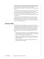
Access Cards
The Models 8965, 8968, 8975, and 8985 access cards are circuit boards
mounted in an 8620 or 8820 Broadband Loop Carrier (BLC), used to transport
Asynchronous Transfer Mode (ATM) cells at high speeds over a single
twisted-pair connection or, optionally, two twisted-pair connections (8985
only). They must be used in conjunction with a Shelf Concentration and
Processing (SCP) card, which is used to configure and monitor the access
cards.
z
z
z
8900-A2-ZZ40-50
Models 8965-B2 and 8968 support Asymmetric Digital Subscriber Line
(ADSL), ADSL2, and ADSL2+ concurrent with POTS. The Model 8965
has 24 DSL ports and the Model 8968 has 48 ports.
Model 8975 supports ADSL or ReachDSL® 2.2 on a port-by-port basis
depending on the capabilities of the line and endpoint. This feature is
known as ReachDSL+.
Model 8985-B2 supports 2-wire and 4-wire Single-pair High-speed
Digital Subscriber Line (SHDSL).
8965, 8968, 8975, and 8985 Access Cards
3
.
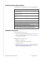
Product Documentation Online
Complete documentation for this product is available at www.zhone.com.
Document Title
Hotwire Central Office Universal POTS Splitter, Models 6050 and 7020,
Installation Instructions
Hotwire ReachDSL Modem, Model 6390 with Inline Phone Filter,
Installation Instructions
Shelf Concentration and Processing (SCP) Card with ATM Uplink User’s
Guide
Shelf Concentration and Processing (SCP) Card with IP Uplink User’s
Guide
Shelf Concentration and Processing (SCP) Card Installation Instructions
8620 Broadband Loop Carrier Installation Guide
8820 Broadband Loop Carrier Installation Guide
Model 8965, 8968, 8975, and 8985 Access Cards User’s Guide
8820 Front Cable Management Bracket Installation Instructions
Installation Overview
Before installing the access card, verify:
z
z
That you have obtained the applicable cables; refer to Cables You Need.
That the 8620 or 8820 Broadband Loop Carrier (BLC) is installed and
power is supplied to the chassis.
Installation of the access card consists of:
z
Installing the card in the BLC.
z
Connecting to a Main Distribution Frame (MDF).
z
Connecting to the uplink.
z
4
Configuring your unit using the web interface. Refer to the SCP card’s
online Help and the Model 8965, 8968, 8975, and 8985 Access Cards
User’s Guide for detailed configuration procedures.
8965, 8968, 8975, and 8985 Access Cards
8900-A2-ZZ40-50
Cables You Need
The following standard cables are used with this product:
z
For the DSL network connection: Plug-ended Telco 50-pin cable for
connection from the BLC rear connector to the MDF or other demarcation
point. Refer to the appropriate BLC Installation Guide and, if applicable,
the documentation that came with your POTS splitter for more
information.
For Model 8968 cards, two cables are required.
z
For the uplink: Refer to the Shelf Concentration and Processing (SCP)
Card with ATM Uplink User’s Guide or Shelf Concentration and
Processing (SCP) Card with IP Uplink User’s Guide for cable
specification information.
For more information refer to Connector Pin Assignments in the Model 8965,
8968, 8975, and 8985 Access Cards User’s Guide.
8900-A2-ZZ40-50
8965, 8968, 8975, and 8985 Access Cards
5
.
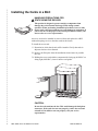
Installing the Cards in a BLC
HANDLING PRECAUTIONS FOR
! STATIC-SENSITIVE DEVICES
This product is designed to protect sensitive components from
damage due to electrostatic discharge (ESD) during normal
operation. When performing installation procedures, however, take
proper static control precautions to prevent damage to equipment. If
you are not sure of the proper static control precautions, contact your
nearest sales or service representative.
An access card can be installed in, removed from, and replaced in a BLC
without disrupting service to the other cards in the chassis.
To install the access card:
1 Determine in which slot the unit will be installed. Verify that cards in
adjacent slots have been fastened.
2 Remove the filler plate from the installation slot and store for possible
later use.
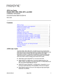
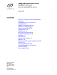
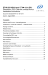
3 Holding the access card with the component side facing up (8620 BLC) or
facing right (8820 BLC), insert it into the card guides.
POWER
A
SYS
ALARMS
B
Fan Major Minor
TEM
SYSTEM
OK
Alm
OK
Test
Alm
Test
ETHERN
ET
ETHERNET
TX
RX
TX
Coll
RX
Coll
DSL
POR
T
1
2
3
4
POWER ENTRY MODULE
LEFT UNIT: LINE A
RIGHT UNIT: LINE B
48V NEG
POWER ENTRY MODULE
LEFT UNIT: LINE A
RIGHT UNIT: LINE B
48V NEG
MCP
48V RTN
48V RTN
DSL
CLOCK SERIAL
AC
A
MCC ALARM
2
4
6
8
B
SERIAL ALARM
CLOCK SMCM
1
3
5
7
LAN/WAN SLOT
A
10
12
14
16
18
11
13
15
17
WARNING! POWER MUST BE
DISCONNECTED AT THE SOURCE
BEFORE REMOVING OR INSTALLING
THIS PWR ENTRY MODULE
WARNING! POWER MUST BE
DISCONNECTED AT THE SOURCE
BEFORE REMOVING OR INSTALLING
THIS PWR ENTRY MODULE
9
B
00-16709
CAUTION:
Do not force the unit into the slot. This could damage the backplane
connectors. If the card does not seat properly, remove the card and
reinstall it. If it still does not seat properly, call your service
representative.
6
8965, 8968, 8975, and 8985 Access Cards
8900-A2-ZZ40-50
4 Slide the unit into the slot until the power and network connectors seat
firmly in the mating connectors on the backplane.
The unit performs a power-on self-test. All of the LEDs turn ON and OFF
briefly. When the self-test is completed successfully, the SYSTEM OK
LED begins to pulse.
If the LED is not pulsing, notify your service representative.
5 Secure the unit by fastening the screws at each end of the faceplate.
Connecting to the ATM or IP Network
The connection to the ATM or IP network is made through the Shelf
Concentration and Processing (SCP) card in the BLC. Depending on the
model, the SCP card supports an OC3/STM1, E1 IMA, DS1 IMA, or Gigabit
Ethernet uplink. See the Shelf Concentration and Processing (SCP) Card
Installation Instructions for more information.
Connecting 24-Port Models to an MDF or POTS Splitter
You can connect 24-port access cards to an MDF or other demarcation point
through the BLC. Do not connect the Model 8985 to a POTS splitter. Refer to
the appropriate BLC Installation Guide for more information.
Refer to Connector Pin Assignments in the Model 8965, 8968, 8975, and 8985
Access Cards User’s Guide for pinouts of the BLC ports.
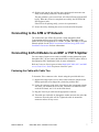
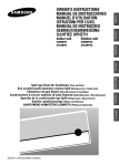
Fastening the Cable with Cable Ties
To fasten the Telco connector to the chassis using the provided cable ties:
1 Replace the longer captive screw on the cable connector with the #4-40
Phillips pan-head screw shipped in a plastic bag with the BLC.
2 Locate the connector on the back of the chassis that corresponds with the
slot where you installed the access card. Connectors are labeled 2 and 3
on the 8620 chassis, and 1–18 on the 8820 chassis.
3 Plug the Telco 50-pin cable into the appropriate connector.
4 Thread the provided cable tie through the anchor mount on the end of the
connector where the cable will lie. Tighten the cable tie around the
connector and cut off any excess.
8900-A2-ZZ40-50
8965, 8968, 8975, and 8985 Access Cards
7
.
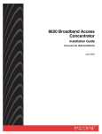
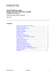
5 Secure the other end of the Telco 50-pin cable by tightening the captive
pan-head screw.
Cable
Tie
Anchor
Mount
Replaced with
Supplied #4-40
Phillips Pan-head
Screw
Telco 50-Pin
Connector
01-16900
6 If a ferrite choke is supplied with your access card, clamp it around the
cable as close as possible to the chassis. If it fits loosely around the cable,
fasten it with a cable tie.
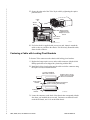
Fastening a Cable with Locking Pivot Brackets
To fasten a Telco connector to the chassis with locking pivot brackets:
1 Replace the longer captive screw on the cable connector with the #4-40
Phillips pan-head screw shipped in a plastic bag with the BLC.
2 Install the locking pivot bracket onto the cable end of the connector using
the captive screw, as illustrated below.
Customer-Supplied
Cable with Connector
Locking Pivot
Bracket
Locking Pivot
Bracket
Replace with a shorter
Captive Screw provided
with the Pivot Bracket
Captive #4-40 Phillips-Head Screw
(Part of Locking Pivot Bracket)
99-16162a-02
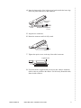
3 Locate the connector on the back of the chassis that corresponds with the
slot where you installed the access card. Connectors are labeled 2 and 3
on the 8620 chassis, and 1–18 on the 8820 chassis.
8
8965, 8968, 8975, and 8985 Access Cards
8900-A2-ZZ40-50
4 Insert the bottom edge of the locking pivot bracket inside the lower edge
of the rear panel cutout next to that connector.
Locking Pivot
Bracket
Rear Panel
Cutout
Receptacle on Backplane
99-16163d-01
5 Align the two connectors.
6 Rotate the connector until it is fully seated.
Rotate
99-16163e-01
7 Tighten the captive screw on the top of the cable's connector.
Tighten Screw
99-16163f-01
8 If a ferrite choke is supplied with your access card, clamp it around the
cable as close as possible to the chassis. If it fits loosely around the cable,
fasten it with a cable tie.
8900-A2-ZZ40-50
8965, 8968, 8975, and 8985 Access Cards
9
.
Connecting a 24-Port Card to the MDF
To connect the BLC containing the card to an MDF:
1 Connect the cable to the chassis as described in Fastening the Cable with
Cable Ties on page 7 or Fastening a Cable with Locking Pivot Brackets
on page 8.
2 Dress the cable to the side the connector is nearest.
3 For a Model 8965, 8975, or 8985 with no POTS service:
— Attach the other end of the cable to the appropriate MDF or
demarcation point. A converter may be necessary for terminating the
other end of the cable on a punchdown block before cross-connecting
to an MDF.
For a Model 8965 or 8975 using an ADSL POTS splitter:
— Attach the other end of the cable to the DSL interface of the POTS
splitter. Refer to the document that came with the POTS splitter for
the additional connections.
10
8965, 8968, 8975, and 8985 Access Cards
8900-A2-ZZ40-50
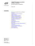
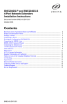
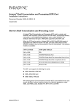
Connecting 48-Port Models to an MDF or POTS Splitter
Connect a 48-port access card such as the Model 8968 to an MDF or other
demarcation point using the connectors on the faceplate of the card.
Connect a cable to the top (8820) or left (8620) connector on the card’s
faceplate for DSL ports 25–48.
DC FUSES
B
-48V
A
13-24
1-12
SCP-IMA
1-12
13-24
/2
2
11
/2
3
12
/2
4
10
1
0
ALT BANK ALT BANK
10
/2
2
11
/2
3
12
/2
4
23
/47
1
0
8/2
9/2
9/2
PO
RT
8/2
9
7/1
6/1
8
PO
RT
5
1/2
11
/3
13 5
/37
9
8
7
6/1
RT
PO
PO
RT
7
R
5/1
1/1 T
3
2/1
4
3/1
5
4/1
6
LK
5
LK
6
LK
7
LK
8
LK
1
LK
2
LK
3
LK
4
K
ALARMS
A
B
7/1
R
SL
D
PO
SL
D
IN
PL
RTN
DC
POWER
A
1 - 24
8968
3
2
1
A
U
ET
A
5/1
1/1 T
3
2/1
4
3/1
5
4/1
6
C
PO
X
R
LO
C
LO
X
R
R
X
ET
N
TX
ER
H
EM
SY
ST
Ac
tiv
Sta e
nd
Ala by
rm
Te
st
SY
AT
M
TX
BU
S
t
Te
s
m
Alr
K
O
ST
EM
SY
AT
M
TX
BU
S
EM
K
Alr
m
Te
st
ST
25 - 48
O
ESD
G.DMT
G.Lite
8965
24
/48
2/2
6
12
/3
14 6
/38
K
Alr
m
Te
st
ADSL2+
Connector 1
O
1-24
SYSTEM
25-48
Connector 2
G.DMT
G.Lite
8965
z
Connect a cable to the bottom (8820) or right (8620) connector on the
card’s faceplate for DSL ports 1–24.
8417
z
B
F
A
N
M
A
J
O
R
M
I
N
O
R
A CLOCK B
ALARM
SCM SERIAL MCP
SCM LAN
MCP
SIM
SIM
AC INPUT
B
04-17508-01
25-48
1-24
SYSTEM
K
O
m
Alr
t
s
Te
25 - 48
Connector 2
5
2/2
1/2
6
/36 /38
12 14
/35 /37
11 13
/48
24
/47
23
1 - 24
Connector 1
ADSL2+
8968
04-17509
8900-A2-ZZ40-50
8965, 8968, 8975, and 8985 Access Cards
11
.
Refer to Connector Pin Assignments in the Model 8965, 8968, 8975, and 8985
Access Cards User’s Guide for pinouts of the access card connectors.
To connect each receptacle of a 48-port access card to an MDF or POTS
splitter:
1 Replace the longer captive screw on your cable connector with the #4-40
Phillips pan-head screw shipped in a plastic bag with the BLC.
2 Install the locking pivot bracket onto the cable end of the connector using
the captive screw, as illustrated below.
Customer-Supplied
Cable with Connector
Locking Pivot
Bracket
Replace with a shorter
Captive Screw provided
with the Pivot Bracket
Captive #4-40 Phillips-Head Screw
(Part of Locking Pivot Bracket)
Locking Pivot
Bracket
99-16162a-02
3 Insert the bottom edge of the locking pivot bracket into the hook next to
the receptacle.
Locking Pivot
Bracket
04-17513
Receptacle on Card
4 Align the two connectors and press the cable connector onto the
receptacle.
5 Tighten the captive screw on the top of the cable's connector.
12
8965, 8968, 8975, and 8985 Access Cards
8900-A2-ZZ40-50
6 Dress the cables toward the nearest rail and fix them with cable ties.
Optionally, use front cable management brackets (feature number
PDN-8900-F1-001) to hold and direct the cables, as shown below. See the
8820 Front Cable Management Bracket Installation Instructions for more
information.
84-52
84-52
ts mr
eT lA KO
84 - 52
ts mr
eT lA KO
METSYS
84 - 52
ts mr
eT lA KO
METSYS
84 - 52
/2
62
+2LSDA
8698
+2LSDA
8698
73 53
/31 /11
73 53
/31 /11
83 63
/41 /21
84
/42
74
/32
42 - 1
42 - 1
83 63
/41 /21
84
/42
83 63
/41 /21
73 53
/31 /11
74
/32
84
/42
42 - 1
42 - 1
+2LSDA
8698
52
/1
62
/2
52
/1
62
/2
8698
73 53
/31 /11
83 63
/41 /21
73 53
/31 /11
+2LSDA
74
/32
84
/42
42 - 1
74
/32
83 63
/41 /21
84
/42
42 - 1
+2LSDA
8698
52
/1
62
/2
52
/1
62
/2
52
/1
62
/2
62
/2
52
/1
73 53
/31 /11
83 63
/41 /21
73 53
/31 /11
83 63
/41 /21
8 6 98
74
/32
84
/42
74
/32
84
/42
42 - 1
+2LSDA
74
/32
ts mr
eT lA KO
42-1
42-1
METSYS
84 - 52
ts mr
eT lA KO
METSYS
84 - 52
ts mr
eT lA KO
METSYS
84 - 52
84 - 52
ts mr
eT lA KO
METSYS
42-1
42-1
42-1
42-1
42-1
METSYS
52
/1
84-52
84-52
84-52
84-52
84-52
+2LSDA
8698
04-17516
7 If ferrite chokes are supplied with your access card, clamp them around
the cables as close as possible to the card. If they fit loosely around the
cables, fasten them with cable ties.
8 For a card without POTS service, attach the other ends of the cables to the
appropriate MDF or demarcation point. A converter may be necessary for
terminating the other end of the cables on a punchdown block before
cross-connecting to an MDF.
For a card with POTS service, attach the other ends of the cables to the
DSL interface of your POTS splitter. Refer to the document that came
with the POTS splitter for the additional connections.
8900-A2-ZZ40-50
8965, 8968, 8975, and 8985 Access Cards
13
.
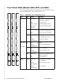
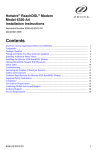
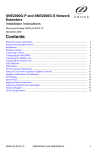
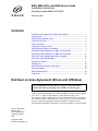
Front Panel LEDs (Models 8965, 8975, and 8985)
The following table describes the meaning and states of the LEDs on the front
panel of the Model 8965, 8975, and 8985 access cards.
Table 1:
Model 8965, 8975, and 8985 LEDs (1 of 2)
SY
SY
ST
O
K
O
K
Al
Al
Al
K
O
S
Green, On
Card failure. System processing
functions have stopped.
Off
No power to card.
Green, Pulsing
Card functioning normally.
Green, Fast
Blinking
Firmware download needed.
Amber, On
Alarm is present on the card. ATM
interface is not being detected.
Off
Normal operation, no alarms.
Amber, On
Test in progress.
Off
Normal operation, no tests.
Amber,
Fast Blinking
Self-test is in progress.
ATM BUS TX
Off
Inactive.
or
Green,
Fast Blinking
Cells are being transmitted.
Off
Inactive, link down.
Green,
Fast Blinking
Cells are being received.
Amber, On
Loss Of Clock. ATM bus clock
signal is not present.
Off
Normal operation.
Green, On
Good signal, unit is trained.
Off
Port is disabled.
Green,
Slow Blinking
Port is in test, or is down.
Green,
Fast Blinking
Port is training.
TX
X
R
X
R
LO
LO
LO
C
TX
X
R
C
TX
C
OK
S
S
S
SYSTEM
BU
BU
BU
Indicating . . .
M
AT
M
AT
SY
LED is . . . a
rm est
T
rm est
T
rm est
T
LED
EM
EM
EM
ST
ST
SY
Type
Alrm
D
D
RT /13 /14 /15 /16
4
PO 1 2 3
RT /13 /14 /15 /16
4
PO 1 2 3
RT /13 /14 /15 /16
4
PO 1 2 3
PO
PO
RT
RT
RT
PO
5/
6/
6/
17
17
5/
6/
17
5/
18
18
18
7/
8/
8/
19
19
7/
8/
19
7/
20
20
20
PO
PO
RT
RT
RT
PO
21
9/
21
9/
21
9/
2
3
/2
11
4
/2
12
4
/2
12
13-24
1-12
1-12
1-12
8975
05-17632
RX
/2
3
/2
11
ALT BANK
13-24
ReachDSL+
SYS BUS
10
2
/2
10
2
4
3
/2 1/2 2/2
1
1
10
ALT BANK
13-24
04-17425-01
14
SL
SL
SL
D
ALT BANK
ATM
ADSL2+
8965
Test
ATM
SHDSL
8985
LOC
DSL
PORT
03-17426
8965, 8968, 8975, and 8985 Access Cards
1–12
13–24
8900-A2-ZZ40-50
Table 1:
Type
ALT
BANK
Model 8965, 8975, and 8985 LEDs (2 of 2)
LED
LED is . . . a
Indicating . . .
Off
The ports not currently displayed
by the port status LEDs are
functioning normally or are
disabled.
Amber,
Fast Blinking
One of the ports not currently
being displayed by the port status
LEDs is down, in test, or in
training mode.
a. Pulsing: LED turns off momentarily once per second.
Slow Blinking: LED turns on momentarily once per second.
Fast Blinking: LED turns off and on in equal duration 4 times per second.
8900-A2-ZZ40-50
8965, 8968, 8975, and 8985 Access Cards
15
.
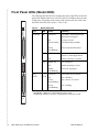
Front Panel LEDs (Model 8968)
The following table describes the meaning and states of the LEDs on the front
panel of the Model 8968 access card. The card has 24 LEDs to show the state
of DSL ports. Depending on the setting of the switch on the face of the card,
the LEDs reflect the state of ports 1–24 or 25–48.
25-48
Table 2:
Model 8968 LEDs
1-24
SYSTEM
O
K
rm st
Al Te
LED
LED is . . . a
Indicating . . .
SYSTEM
OK
Green, On
Card failure. System processing
functions have stopped.
Off
No power to card.
Green, Pulsing
Card functioning normally.
Green,
Fast Blinking
Firmware download needed.
Amber, On
Alarm is present on the card. ATM
interface is not being detected.
Off
Normal operation, no alarms.
Amber, On
Test in progress.
Off
Normal operation, no tests.
Amber,
Fast Blinking
Self-test is in progress.
Green, On
Good signal, unit is trained.
Off
Port is disabled.
Green,
Slow Blinking
Port is in test, or is down.
Green,
Fast Blinking
Port is training.
25 - 48
Type
Alrm
6
2/2
5
1/2
Test
/35 /37
11 13
/36 /38
12 14
/47
23
/48
24
DSL
PORT
1–24
25–48
1 - 24
a. Pulsing: LED turns off momentarily once per second.
Slow Blinking: LED turns on momentarily once per second.
Fast Blinking: LED turns off and on in equal duration 4 times per second.
ADSL2+
8968
04-17507
16
8965, 8968, 8975, and 8985 Access Cards
8900-A2-ZZ40-50
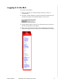
Logging In to the BLC
To access the web interface:
1 Open your web browser. (Internet Explorer Version 6 or above is
recommended.)
2 Type http:// and the IP address of the SCP card into the Address field of
your browser window. The default IP address is 10.10.10.10:
3 A login window appears. Enter the User ID and Password, and click on
OK. The web interface screen appears.
4 Click on the Configuration menu tab. The configuration screens listed
depend on the types of access cards and SCP card installed in the chassis.
8900-A2-ZZ40-50
8965, 8968, 8975, and 8985 Access Cards
17
.
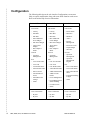
Configuration
The following table shows the web interface Configuration screens most
likely to require modification, along with some fields found on each screen.
Refer to the online Help for more information.
Models 8955 and 8975 Models 8965 and 8968 Model 8985
DSL
z
z
Line Profile
DSL
z
z
Line Profile
– Latency
– Latency
– Profile Name
– Max Rate
– Max Rate
– Max Rate
– Min Rate
– Min Rate
– Min Rate
– Max Additional
Noise Margin
– Max Additional
Noise Margin
– Annex
– Min Noise Margin
– Min Noise Margin
– Target Noise
Margin
– Target Noise
Margin
– Rate Adaptive
Mode
– Rate Adaptive
Mode
General
z
– Spectrum
Management
z
Line Profile
SHDSL
Port
z
General
– Remote
Management
– Reference Clock
– Target Margin
– Wire Pair
z
General
– Spectrum
Management
– Spectrum
Management
Port
– Spectrum
Management
Region
– Line Circuit Name
– Line Circuit Name
– Line Code
– Line Code
– Line Profile Name
– Line Profile Name
– Line Circuit Name
– Alarm Profile Name
– Alarm Profile Name
– Line Profile Name
– Max Tx Power
– ADSL2 PSD Profile
– Far End Max Tx
Power
– ADSL2+ PSD
Profile
– Span Alarm Profile
Name
– POTS Detection
Voltage
– Power Management
z
– Equivalent Working
Length
– Status
– Power Management
Status Enabling
– Status
Port
– L0 and L2 Time
– Status
ATM
z
18
Cross Connections
ATM
z
Cross Connections
ATM
z
Cross Connections
– By Port
– By Port
– By Port
– By Slot
– By Slot
– By Slot
8965, 8968, 8975, and 8985 Access Cards
8900-A2-ZZ40-50
Contacting Global Service and Support
Contact Global Service and Support (GSS) if you have any questions about
this or other Zhone products. Before contacting GSS, make sure you have the
following information:
z
Zhone product you are using
z
System configuration
z
Software version running on the system
z
Description of the issue
Technical Support
If you require assistance with the installation or operation of your product, or
if you want to return a product for repair under warranty, contact GSS. The
contact information is as follows:
E-mail
[email protected]
Telephone (North America)
877-ZHONE20
Telephone (International)
510-777-7133
Internet
www.zhone.com/support
If you purchased the product from an authorized dealer, distributor, Value
Added Reseller (VAR), or third party, contact that supplier for technical
assistance and warranty support.
Service Requirements
If the product malfunctions, all repairs must be performed by the
manufacturer or a Zhone-authorized agent. It is the responsibility of users
requiring service to report the need for service to GSS.
Trademarks
Hotwire and ReachDSL are registered trademarks of Zhone Technologies,
Inc. All other products and services mentioned herein are the trademarks,
service marks, registered trademarks, or registered service marks of their
respective owners.
Copyright 2005 Zhone Technologies
8900-A2-ZZ40-50
8965, 8968, 8975, and 8985 Access Cards
19
.
*8900-A2-ZZ40-50*
*8900-A2-ZZ40-50*
20
8965, 8968, 8975, and 8985 Access Cards
8900-A2-ZZ40-50