1
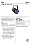
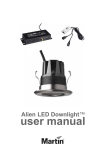
V-Flex
®
High Output UV Device
INSTALLER/OWNER’S GUIDE
Specifications subject to change without notice.
©Altru-V and V-Flex are brands owned by UVDI.
Copyright © 2003 by UltraViolet Devices, Inc. All rights reserved.
19-2021 Rev E, 06/05/07
1
TABLE OF CONTENTS
SPECIFICATIONS........................................................................................................... 3
Electrical Ratings ....................................................................................................... 3
Approvals ..................................................................................................................... 3
APPLICATION.................................................................................................................. 4
INSTALLATION ............................................................................................................... 4
MOUNTING LOCATION ................................................................................................. 5
INSTALLATION OF THE LAMP MODULES.............................................................. 6
INSTALLATION OF THE POWER JUNCTION MODULE ....................................... 8
INSTALLATION OF MAIN SUPPORT INTO AIR HANDLING DUCT.................... 9
ELECTRICAL CONNECTION OF THE SYSTEM.................................................... 10
LAMP INSTALLATION ................................................................................................. 10
OPERATION ................................................................................................................... 13
TROUBLESHOOTING AND SERVICE ..................................................................... 13
Cleaning the Lamps................................................................................................. 14
Replacing the Lamp (Annually) ............................................................................ 14
EQUIPMENT WARRANTY .......................................................................................... 16
19-2021 Rev E, 06/05/07
2
SPECIFICATIONS
Electrical Ratings
Power Ratings
Note: The V-Flex is a universal input circuit capable of operation at 120 Vac or 240 Vac and 50Hz
or 60Hz.
The unit is designed to be hardwired to an appropriate electrical service in accordance with NEC.
Temperature Ratings
Ambient Temperature Range: 40°F to 135°F (4°C to 51°C)
Lamp Temperature Range: 40°F to 135°F (4°C to 51°C)
Relative Humidity: Up to 95% rh, non-condensing
Power Consumption
Model
Input Current
(A)
Lamp Wattage
(W)
120V
0.6
60
240V
0.3
60
Approvals
Underwriters Laboratories: File no. E212213. Category Code ABQK (Accessories, Air Duct
Mounted) UL Standards: UL153, UL1598 & UL1995. The health aspects associated with the use
of this product and its ability to aid in disinfection of environmental air have not been investigated
by UL. This product is classified only when installed with accompanying part numbers 19-1020,
19-1030, 19-3004 and 19- 3005.
Figure 1. V-FlexTM Lamp Module
19-2021 Rev E, 06/05/07
3
APPLICATION
When installed in forced air heating and cooling systems, the V-Flex kills airborne and surface
microorganism contaminants. It is designed to be mounted in-duct for airborne, “on-the-fly”
applications as well as surface irradiation applications. The design allows for many different
levels of UV dosage. Proper dosage is affected by many factors, such as air temperature,
velocity, and duct reflectivity. The space between supports (typically 32”) and the space between
rows (typically 24” for surfaces and 12” to 18” for moving air streams) can be increased or
reduced to adjust for dosage.
See your Altru-V dealer or sales representative for assistance, as required.
INSTALLATION
1.
2.
3.
4.
5.
6.
Read these instructions carefully. Failure to follow the instructions could damage the
product or cause a hazardous condition.
Check the electrical rating given in the instructions and on the product to make sure the
product is suitable for your application.
To avoid accidental exposure to ultraviolet light, the power supply to this product
must be electrically interlocked. Interlock switches must be installed at any
access panel or door within view of the UV fixtures.
The installer must be a trained, experienced service technician.
After installation is complete, check out product operation as provided in this guide.
If the HVAC system has been in use prior to installation, it is recommended that debris
and buildup on coils and HVAC system surfaces be cleaned.
Product Registration
Thank you for purchasing this product from UVDI! Prior to any other installation activities,
please proceed with registering you product via the web at http://www.altruv.com or by
returning the enclosed self-addressed postcard. Product registration will insure that your
warranty is handled in a proper and expeditious manner. In addition, it will allow UVDI to
provide you with important updates regarding your new product including reminders of
when replacement parts are needed and also make you eligible for future parts discounts
CAUTION
Personal Injury Hazard
Power supply can cause electrical shock.
Disconnect power supply before beginning installation. Do not open lamp knob. There are no
user serviceable components inside. Professional installation is required per NEC standards .
WARNING
UV Light Hazard
Harmful to bare skin and eyes.
Can cause temporary or permanent loss of vision.
19-2021 Rev E, 06/05/07
4
Never look at the lamps while illuminated. Only view illumination by way of view port accessory.
To prevent exposure to ultraviolet light, disconnect power to the V-Flex before servicing any part
of the HVAC system.
MOUNTING LOCATION
CAUTION
Equipment Damage Hazard
Ultraviolet light can cause color shift or structural degradation of plastic
HVAC materials.
Select mounting location that prevents exposure to plastic components with unknown resistance
to ultraviolet light. It is recommended that there be a minimum of three-feet between ultraviolet
lamps and plastic-fabricated devices (such as non-fiberglass media filters).
CAUTION
Equipment Damage Hazard
Ultraviolet light can cause color shift or surface degradation and
sometimes structural degradation of non-metallic components.
Select a mounting location that prevents exposure to plastic flexible duct components,
polyurethane foam insulation material, rubber hoses, wire insulation, etc. If mounting options are
limited, items above should be protected with ultraviolet resistant material such as aluminum foil,
aluminum duct tape, or metallic shields or equivalent.
1.
Inspect and determine an appropriate location inside the air handling system for the
installation. The location should allow for the mounting of a bracket on the floor and the
ceiling of the air handler and should be readily accessible for the cleaning of lamps and
the annual replacement of lamps (see Figure 2a).
Record Dimensions:
Dimension A Dimension B Dimension C
Figure 2a
19-2021 Rev E, 06/05/07
5
2.
3.
4.
5.
6.
7.
Determine the number and configuration of Lamp Modules and Power Junction Modules.
Note: the maximum number of Lamp Modules (19-1000) to be installed per Power
Junction Module (19-1020) is 24.
Mark the location of the lower mounting bracket on the lower mounting surface of the
installation area.
Measure overall length/height required for the installation (Figure 2a, dimension ‘A’).
This dimension is the distance from the lower mounting surface to the upper
mounting surface of the mounting location. Record the measurement in the table in
Figure 2a. for Dimension A.
Referencing Dimension A, deduct ½” from the overall distance from the lower to
upper mounting surface and record as Dimension B. This is the overall length of the
Main Support.
Install the lower bracket to the lower mounting surface of the installation area in the
previously marked location. Four sheet metal screws (provided) should be used to
securely fasten the lower bracket to the lower mounting surface (see Figure 2a).
Place the Main Support on a horizontal surface in an appropriate work area.
Measure and mark off the Dimension B onto the Main Support (see Figure 2b).
Then make one cut through the cross-section of the Main Support using a tool
appropriate for cutting aluminum. Cut only from one end, as it is important to retain a
wiring feed-through hole in the Main Support section to be installed.
Figure 2b
INSTALLATION OF THE LAMP MODULES
1.
2.
3.
4.
5.
6.
7.
Carry the Main Support into the installation area. Place the upper mounting bracket
onto the top end of the Main Support. Do not install screws in the upper
mounting bracket at this time.
Place the lower end of the Main Support into the lower mounting bracket, which is
secured to the lower mounting surface.
Swing the Main Support into place so that it is vertical.
When vertical, use the supplied hardware to anchor the upper mounting bracket into
the duct ceiling.
First mark the location where the Power Junction Module is to be attached. It is
important to mount the Power Junction Module near, but not covering, the wire feed
through hole in the Main Support. It is recommended that the Power Junction
Module be attached to the upper end of the Main Support.
Mark the Main Support locations where the Lamp Modules should be attached.
Note: the maximum number of Lamp Modules (19-1000) to be installed per
Power Junction Module (19-1020) is 24.
Once the desired locations for the Lamp Modules and Power Junction Modules have
been identified, disassemble the upper mounting bracket from the upper mounting
surface and return the Main Support to the work area.
19-2021 Rev E, 06/05/07
6
8.
Select one side of the Main Support to start assembly of lamp modules. Begin
assembly of the Lamp Modules attachments first (see Figure 3b). Begin by installing
the Lamp Module furthest from the Power Junction Module location.
9. Thread the three wires from the last Lamp Module installed to the main extrusion
through the strain relief and into the wiring compartment of the next Lamp Module.
10. Route the external wires from the Lamp Modules into the Main Support wire raceway.
Attach Lamp Modules to the Main Support with supplied screws (4) as shown (See
Figure 3b).
Figure 3a
Figure 3b
11. Prepare next Lamp Module for attachment by removing wire access cover and
loosening strain-relief screws.
12. Thread the three wires from the last Lamp Module installed to the Main Support
through the strain relief and into the wiring compartment of the next Lamp Module.
13. Route the external wires from the Lamp Module under installation into the Main
Support wire raceway and attach next Lamp Module to support with four screws.
14. Tighten strain-relief screws to secure the external power wires
15. Cut, as required, and strip 3/8" from the wires and insert into respective WAGO
connector terminals (black-black, white-white, green-green)
16. Fold cables into Lamp Module enclosure and attach the wire access cover.
17. Repeat steps 5–14 as required until all Lamp Modules to be installed on the present
side of the Main Support are installed.
18. Proceed to install Lamp Modules to the second Lamp Module mounting side of the Main
Support.
19. Begin by installing the Lamp Module furthest from Power Junction Module. Repeat the
instructions included in steps 5 through 14.
19-2021 Rev E, 06/05/07
7
20. After installation of the last Lamp Module on the side opposite of the Power Junction
Module, route the power wires from the last Lamp Module installed through the feed
through hole connecting the wire raceway from either side. Do not install lamps at this
stage. (see Figure 3c for example of completely wired system)
Figure 3c
INSTALLATION OF THE POWER JUNCTION MODULE
Figure 4a
21. Remove Power Junction Module cover.
22. Thread wires from last Lamp Module installed on each side through Power Junction
Module strain relief (See Figure 4a).
23. Attach Power Junction Module to support with screws provided (2) as shown in
Figure 4a.
24. Pull wires through strain relief until slack is removed and tighten strain relief screws
to secure the wires entering the Power Junction Module
25. Cut and strip wires, 3/8", and insert into respective WAGO connector terminals
(black-black, white-white, green-green), as required.
26. Fold cables into Power Junction Module enclosure.
PREPARATION OF THE WIRE/RACEWAY COVER
Raceway
19-2021 Rev E, 06/05/07
8
IMPORTANT
It is a requirement to incorporate the wire raceway covering to all exposed portions of
the wire raceway on the mounting sides of the Main Support where modules have been
mounted.
27. Identify, measure and record all spaces on the Main Support between Lamp Modules
and the Power Junction Module (see Figure 2b).
28. Place the bare wire/raceway cover onto a horizontal surface in an appropriate work
area. Mark off the dimensions corresponding to the gap dimensions recorded in step
7 onto the raceway cover sections. Make one cut through the cross-section of the
raceway cover for each space identified using a tool appropriate for cutting
aluminum.
29. Install (press fit) the raceway covers onto the Main Support for all gaps existing in the
Main Support raceway.
INSTALLATION OF MAIN SUPPORT INTO AIR HANDLING DUCT
1.
Carefully carry the partially assembled Main Support into the installation area.
With bottom mounting bracket
screwed to extrusion and top
mounting bracket loose on extrusion
set bottom down on mounting surface
Figure 6a
2.
3.
4.
5.
6.
7.
and swing up into position.
Place the second mounting bracket onto the top end of the Main Support. Do not
install screws into the top end bracket at this stage.
Place the lower end of the Main Support into the lower mounting bracket, which is
secured to the lower mounting surface.
Swing the Main Support into place so that it is vertical.
When vertical, use the supplied hardware to anchor the upper mounting bracket into
the duct ceiling.
Anchor the Main Support to the lower mounting bracket using two screws.
Anchor the Main Support to the upper mounting bracket using two screws.
19-2021 Rev E, 06/05/07
9
ELECTRICAL CONNECTION OF THE SYSTEM
WARNING
Personal Serious Injury Hazard
Power supply can cause severe electrical shock.
Disconnect power supply before installation. All wiring should be in accordance with NEC.
1.
2.
3.
4.
Bring power to the Power Junction Module and use appropriate knock-out on the
Power Junction Module.
Install power conduit connector.
Using supplied WAGO connector terminals, connect assembly wires to power supply.
(Line in to black, neutral to white, and earth ground to green).
Attach the Power Junction Module cover with two nuts.
WARNING
UV Light Hazard
Harmful to bare skin and eyes.
Can cause temporary or permanent loss of vision.
Never look at the lamps while illuminated. Only view illumination by way of view port accessory.
To prevent exposure to ultraviolet light, disconnect power to the V-Flex T M before servicing any
part of the HVAC system.
WARNING
The electrical supply circuit connected to this UV appliance must be routed through an electrical
interlock switch placed on the HVAC system duct access panels and doors to prevent accidental
UV exposure when servicing the air ducts or equipment.
LAMP INSTALLATION
CAUTION
Breakable Glass Hazard
Can cause personal injury.
Be careful when inserting lamp into lamp base. Wear protective gloves when handling lamp.
1.
To install lamps into Lamp Modules. Slide lamp and black clip into the lamp module
as shown in the below picture:
19-2021 Rev E, 06/05/07
10
19-2021 Rev E, 06/05/07
11
2.
Insert the black V-Flex Clip into the module so that is holding the lamp in place and
the clip is secured onto the metal module. Make sure the clip is slid over the lamp
module as shown below:
3.
4.
Push the lamp in till it snaps into place. Verify that lamp is retained.
Lamp should not have any slack to move.
19-2021 Rev E, 06/05/07
12
WARNING
UV Light Hazard
Harmful to bare skin and eyes.
Can cause temporary or permanent loss of vision.
Never look at the lamps while illuminated. Only view illumination by way of view port accessory.
To prevent exposure to ultraviolet light, disconnect power to the V-Flex before servicing any part
of the HVAC system.
WARNING
Prevent accidental exposure to service personnel.
Install interlock switches on all access doors and affix UV warning labels to
HVAC equipment.
5.
6.
7.
Reconnect the power to the HVAC system.
Choose a location on the adjacent HVAC equipment for the HVAC maintenance label
included in the V-Flex Lamp Module packing box. Choose a location that a future
installer can easily see during all future HVAC maintenance or repair.
Adhere the HVAC maintenance label to the HVAC equipment access door or panel.
CHECKOUT
The installer should verify that the ultraviolet lamps are operating only by viewing through view
port accessory. Do not attempt to look directly into the duct to see the illuminated ultraviolet
lamp. The installer should orient the owner to the unit by demonstrating use of the view port
accessory and discussing how to determine when the unit is functioning properly without looking
directly into the duct to see the illuminated ultraviolet lamp. The installer should also emphasize
the hot surface and electrical shock safety warnings. The installer should leave the product data
with the owner and review the lamp cleaning and lamp replacement procedures.
OPERATION
TROUBLESHOOTING AND SERVICE
The V-Flex has no field-serviceable parts. Lamp cleaning is recommended as routine
maintenance four times a year, or every three months (quarterly). Annual lamp replacement
is required. See the Replacing the Lamp (Annually) section for detailed procedural
information.
MERCURY NOTICE
This device contains mercury in the sealed ultraviolet lamp. Do not place your used lamp in the
trash. Dispose of properly.
Broken Lamp Clean-up
Do not use a household vacuum. Sweep debris into a plastic bag and dispose of properly.
Contact your local waste management authority for instructions regarding recycling and the
proper disposal of old lamp.
19-2021 Rev E, 06/05/07
13
CAUTION
UV Lamp Burn Hazard
Harmful to bare skin. Can cause severe burns.
Disconnect power 15 minutes before removing the ultraviolet lamp.
WARNING
UV Light Hazard
Harmful to bare skin and eyes.
Can cause temporary or permanent loss of vision.
Never look at the lamps while illuminated. Only view illumination by way of view port accessory.
WARNING
UV Light Hazard.
Harmful to skin and eyes.
Can cause temporary or permanent loss of vision.
Never look at the lamp while illuminated.
Cleaning the Lamps
Use alcohol or glass cleaner. Do not touch.
Depending upon operating conditions, lamp cleaning is recommended as routine maintenance up
to four times a year, when necessary. If the air stream is filtered, cleaning schedule may be
reduced.
To clean the lamp:
1.
2.
3.
4.
5.
6.
7.
8.
Disconnect power to HVAC system. Never enter system with UV lamps illuminated.
Open the system access panel or door.
Allow the lamp to cool for at least 15 minutes.
Wipe the lamp glass using a soft cloth with window cleaner applied to the cloth. Do not
touch the lamp surface with your hands; use only the cloth.
Wipe the lamp with a clean, dry cloth as a dirty cloth can cause the lamps to soil more
quickly.
Reconnect the power to your HVAC system.
Replace and lock enclosure cover.
Verify that the ultraviolet lamp is operating only by viewing through the view port
accessory. Never look directly at the lamp while illuminated.
Replacing the Lamp (Annually)
Annual replacement of the lamp is required. To replace the lamp:
1.
2.
Disconnect the power to the HVAC system.
Open the access door or panel.
19-2021 Rev E, 06/05/07
14
3.
4.
5.
6.
7.
Allow the lamp to cool for at least 15 minutes.
Depress lamp release button and remove lamp. Be careful not to strike or hit the lamp
glass with the enclosure edges.
Insert new lamp into the Lamp Module. Depress lamp release button and insert lamp.
Let go of the lamp release button and verify that lamp is retained.
Reconnect the power to the HVAC system.
Clean the lamp (see Cleaning the Lamps) to remove any fingerprints or dirt on the glass.
This device contains mercury in the sealed ultraviolet bulb(s). Do not place your
used bulb(s) in the trash. Dispose of properly.
19-2021 Rev E, 06/05/07
15
EQUIPMENT WARRANTY
UltraViolet Devices, Inc. (UVDI), warrants to original Buyer for one year from the date of
original installation, or eighteen (18) months from date of shipment, whichever comes first, that its
goods are free from defect in material and workmanship under normal use and service. UVDI’s
obligation under this warranty shall be limited to the repair or replacement of those goods which
prove defective, provided that such products are installed, maintained, and operated for the
purpose and in the manner intended and for which UVDI instructs or recommends. Neither UVDI
nor its dealers shall be liable for any special or consequential damages directly or indirectly
arising from the design, construction, installation, servicing, or operation of the goods. THIS IS
UVDI’S SOLE WARRANTY. NEITHER UVDI NOR ITS DEALERS MAKE ANY OTHER
WARRANTY OF ANY KIND, EXPRESSED OR IMPLIED. ALL IMPLIED WARRANTIES OF
MERCHANTABILITY AND FITNESS FOR A PARTICULAR PURPOSE WHICH EXCEED UVDI’S
AFFORESTATED OBLIGATIONS ARE HEREBY DISCLAIMED AND EXCLUDED FROM THIS
WARRANTY.
UVDI AND ITS DEALERS’ LIABILITY UNDER THIS WARRANTY SHALL IN NO EVENT
EXCEED THE COST OF THE GOODS SOLD UNDER THIS CONTRACT OF SALE. UVDI
neither assumes, nor authorizes any person to assume for it, any obligation in connection with the
goods. This warranty shall not apply to any goods (a) which have been subjected to misuse,
tampering, negligence, or accidents; or (b) the serial numbers of which have been altered,
defaced, or removed; or (c) which have been used in a manner contrary to UVDI’s instructions or
recommendations. Buyer shall not return to UVDI any allegedly defective goods without UVDI’s
prior written authorization. This warranty may not be assigned or transferred.
Product Registration
It is highly recommended that you register you product via the web at http://www.altruv.com/ or
return the enclosed self-addressed postcard to UVDI. Product registration will insure that your
warranty is handled in a proper and expeditious manner. In addition, it will allow UVDI to provide
you with important updates regarding your new product including reminders of when replacement
parts are needed and also make you eligible for future parts discounts.
Manufactured by:
26145 Technology Drive
Valencia, CA 91355
(877) PUREUVC
(661) 257-4698 fax
www.uvdi.com & www.altruv.com
Specifications subject to change without notice.
©Altru-V and V-Flex are brands owned by UVDI.
Copyright © 2003 by UltraViolet Devices, Inc. All rights reserved.
19-2021 Rev E, 06/05/07
16