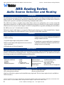
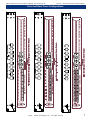
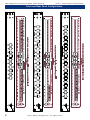
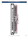
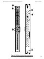
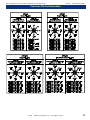
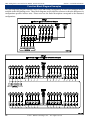
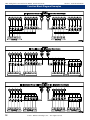
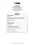
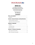
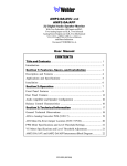
1
ARS Analog Series
Analog Audio Source Selection
and Signal Routing Unit with 5 to 40
Inputs and 1 to 8 Outputs On Single
or Dual Connectors
Document P/N 821518 Rev-B
User and Service Manual
CONTENTS
Title and Contents ....................................................... 1
Introduction .................................................................................. 2
Section 1: General Features and Specifications... 3
General Description, Features, Applications, Specifications,
and Special Options ..................................................................... 4
Front and Rear Panel Configurations ........................................... 5
Section 2: Operation
.................................................. 13
Installation .................................................................................... 15
Front and Rear Panel Features ..................................................... 16
Section 3: Technical Information.............................. 19
Connector Pin-Out Information...................................................... 20
Function Block Diagram Examples................................................ 22
General Circuit Description........................................................... 26
Appendix A: PCB Layouts and Schematics ............ 27
111301
1
Important Safety Instructions
1)
Read these instructions.
2)
Keep these instructions.
3)
Heed all warnings.
4)
Follow all instructions.
5)
Do not use this apparatus near water.
6)
Clean only with dry cloth.
7)
Do not block any ventilation openings. Install in accordance with the manufacturer's instructions.
8)
Do not install near any heat source such as radiators, heat registers, stoves, or other apparatus (including
amplifiers) that produce heat.
9)
Do not defeat the safety purpose of the polarized or grounding-type plug. A polarized plug has two blades
with one wider than the other. A grounding type plug has two blades and a third grounding prong. The
wide blade or the third prong are provided for your safety. If the provided plug does not fit into your outlet,
consult an electrician for replacement of the obsolete outlet.
10) Protect the power cord from being walked on or pinched, particularly at plugs convenience receptacles
and the point where they exit from the apparatus.
11) Only use attachments/accessories specified by the manufacturer.
12) Use only with the cart stand, tripod, bracket, or table specified by the manufacturer, or sold with the
apparatus. When a cart is used, use caution when moving the cart/apparatus combination to avoid injury
from tip-over.
13) Unplug this apparatus during lightning storms or when unused for long periods of time.
14) Refer all servicing to qualified service personnel. Servicing is required when the apparatus has been
damaged in any way, such as when power-supply cord or plug is damaged, liquid has been spilled or
objects have fallen into the apparatus, the apparatus has been exposed to rain or moisture, does not
operate normally, or has been dropped.
15) Do not expose this apparatus to rain or moisture.
16) The apparatus shall be connected to a mains socket outlet with a protective earthing connection.
CAUTION!
In products featuring an audio amplifier and speakers, the surface at the side of the
unit, where the audio amplifier heat sink is internally attached, may get very hot after
extended operation. When operating the unit excercise caution when touching this
surface and ensure that external materials which may be adversely affected by heat
are not in contact with it. There is a Hot Surface label (see diagram) attached to the
aforementioned surface of the product.
Introduction
Congratulations on your selection of a Wohler Technologies product. We are confident it represents the best performance and value
available, and we guarantee your satisfaction with it.
If you have questions or comments you may contact us at:
Wohler Technologies, Inc.
31055 Huntwood Avenue
Hayward, CA 94544
Phone: (510) 870-0810
Fax: (510) 870-0811
US Toll-Free: 1-888-596-4537
www.wohler.com
2
[email protected]
© 2007 Wohler Technologies, Inc. ALL rights reserved
ARS Analog Series User and Service Manual P/N 821518 Rev-B
Sect. 1: General Features and Specifications
Section 1
General Features
and Specifications
Description
Features
Applications
Specifications
Special Options
Front and Rear Panel Configurations
© 2001
Wohler Technologies Inc. ALL rights reserved
3
ARS Analog Series User and Service Manual P/N 821518 Rev-B
Section 1: General Features and Specifications
ARS Analog Series
Audio Source Selection and Routing
Description
The ARS Analog series from Wohler Technologies provides electronic switching for multiple audio sources in a
single rack space. An ARS unit may function as a stand-alone audio routing switcher, or as the source selector in
an interactive system for aural and visual monitoring of multiple audio sources.
The ARS Series features a modular design which allows units to be configured to suit a variety of specific
application requirements. An ARS unit can be configured to accept up to 40 mono or 20 stereo inputs, with signals
routed to one or two stereo or mono outputs. A total of 19 configurations are possible, including one which allows
the ARS to serve as a 5 x 4 audio matrix switcher.
Balanced or single-ended inputs are accepted on Phoenix style, plug-in, screw clamp terminal blocks. Outputs
may be either balanced or single-ended on 3-pin or 5-pin XLR or 8-pin DIN connectors.
Features
•Single rack space
•Tactile switches offer "radio button" style single
channel selection with the additional flexibility of
multiple channel selection.
•CMOS switching
•19 possible input/output configurations available.
•Mono or stereo inputs with output on one or two mono or
stereo connectors.
•Comprehensive system application in conjunction
with Wohler AMP Series monitors and LM Series
multiple source level metering.
•LED indication of selected channel(s).
Applications
The ARS Analog series is ideally suited for use in broadcast, recording, corporate and industrial video, satellite link
facilities, and commercial sound applications. Designed and manufactured in the U.S., the ARS Series is backed
by a strong warranty and a satisfaction guaranteed return policy.
Specifications
Input Impedance (min.):
Input Level: (maximum):
Crosstalk:
Distortion:
Frequency Response:
40 kΩ (Ohm) balanced
+26 dBv
-65 dB
Less than 0.05%
± .5 dB 20 Hz - 20 kHz
Noise:
-65 dB
Maximum Output:
+20 dBv into 600Ω (Ohm)
Dimensions (H x W x D) 1.75 x 19 x 6 inches
(44.5 x 483 x 149 mm)
Weight (maximum):
7 lbs. (3.18 kg)
Power Supply:
24 VAC; UL, CSA, or TUV approved
Special Options
•Pair of tri-color LED level meters
•IPI-1 phase/polarity indicator
•Remote control input-output
•Rotary switch activation
(Only one of the above options can be installed on any single unit. The level meter option is not is available on
ARS-4x models.)
Units are certified to meet, at time of manufacture, all currently applicable product safety and EMC requirements, such as those of UL
and CE. 0 dbV ref. 0.775V RMS. Features and specifications subject to improvement without notice.
© 2001 Wohler Technologies Inc. ALL rights reserved
4
ARS Analog Series User and Service Manual P/N 821518 Rev-B
Section 1: General Features and Specifications
ARS Series Front and Rear Panel Configurations
© 2001
Wohler Technologies Inc. ALL rights reserved
5
ARS Analog Series User and Service Manual P/N 821518 Rev-B
Section 1: General Features and Specifications
Front and Rear Panel Configurations
6
© 2001 Wohler Technologies Inc. ALL rights reserved
ARS Analog Series User and Service Manual P/N 821518 Rev-B
Section 1: General Features and Specifications
Front and Rear Panel Configurations
© 2001
Wohler Technologies Inc. ALL rights reserved
7
ARS Analog Series User and Service Manual P/N 821518 Rev-B
Section 1: General Features and Specifications
Front and Rear Panel Configurations
8
© 2001 Wohler Technologies Inc. ALL rights reserved
ARS Analog Series User and Service Manual P/N 821518 Rev-B
Section 1: General Features and Specifications
Front and Rear Panel Configurations
© 2001
Wohler Technologies Inc. ALL rights reserved
9
ARS Analog Series User and Service Manual P/N 821518 Rev-B
Section 1: General Features and Specifications
Front and Rear Panel Configurations
10
© 2001 Wohler Technologies Inc. ALL rights reserved
ARS Analog Series User and Service Manual P/N 821518 Rev-B
Section 1: General Features and Specifications
Front and Rear Panel Configurations
© 2001
Wohler Technologies Inc. ALL rights reserved
11
ARS Analog Series User and Service Manual P/N 821518 Rev-B
12
© 2001 Wohler Technologies Inc. ALL rights reserved
ARS Analog Series User and Service Manual P/N 821518 Rev-B
Section 2
Operation
Installation
Front and Rear Panel Features
© 2001
Wohler Technologies Inc. ALL rights reserved
13
ARS Analog Series User and Service Manual P/N 821518 Rev-B
14
© 2001 Wohler Technologies Inc. ALL rights reserved
Section 2: Operation
ARS Analog Series User and Service Manual P/N 821518 Rev-B
Section 2: Operation
Installation
Mounting
The ARS unit should be mounted in a rack or console where convenient for the expected level of operation. If only
occasional operation is expected, the unit might be located higher or lower in the rack than would be advisable if
it is expected to be used frequently. The unit's chassis is only six inches deep, so it may be more convenient to connect
the cables from in front of the rack. This would be especially useful where the ARS unit is adjacent to equipment
with a fairly deep chassis. In that case, when attaching the plug-in terminal blocks, be sure that the cables are long
enough to reach through the front of the rack.
Heat Dissipation
Heat produced by these units is negligible. No special considerations for cooling are necessary as long as the
ambient temperature inside the rack area does not exceed approximately 40°C (104°F).
Mechanical Bracing
The chassis is securely attached to the front panel at six points along its surface, not just at the four corners of the
chassis ears. This feature will reduce or eliminate rear bracing requirements in most mobile/portable applications. The weight of internal components is distributed fairly evenly around the unit.
Electrical Interference
As with any audio equipment, maximum immunity from electrical interference requires the use of shielded cable;
however, satisfactory results can sometimes be obtained without it.
Power Supply
The ARS Series is powered by an external Universal Input/24VDC desktop power supply through a DC input
connector at the rear panel. Since the opamp circuitry normally requires a split supply, a bias source is created at
1/2 the 24VDC level for proper opamp biasing.
Audio Connections
All input connections are on "Phoenix" style, screw clamp, plug-in terminal block connectors. Each input channel
is on a separate plug-in terminal block. For connection to a single-ended (unbalanced) source, the unused input
terminal must be jumpered to circuit common, which is easily done on the plug-in terminal block.
Output connectors are male XLR with three or five pins, or female DIN with 8 pins depending on the model. See
page 20, in the Technical Information section for pin-out information for all models.
© 2001
Wohler Technologies Inc. ALL rights reserved
15
ARS Analog Series User and Service Manual P/N 821518 Rev-B
Section 2: Operation
Front Panel Features
Please refer to Figure-2a on the following page to familiarize yourself with the front panel features of the ARS
Analog series units. The following sections describe these features and are referenced, by number, to Figure-2a.
Note: Only one of seven possible front panel configurations is shown in Figure-2a (Model ARS-44B). However,
all controls and indicators function the same across the entire line of analog ARS models. See pages 6-11 for
illustrations of all front panel configurations available in the ARS Analog series.
1
Channel Select - Push Buttons
Push one of these buttons to select the input channel that will be routed to the configured output connector(s).
A single push selects the indicated channel. A green LED above the button (See Item 2, below) will light
up to indicate that the channel is selected. Pushing another Channel Select button selects a different channel
and automatically de-selects the previously selected channel. To select more than one channel, push on
one of the Channel Select buttons for a desired channel and hold it down while pressing additional buttons
one at a time, until all desired additional channels are selected.
2
Channel Select Indication - Green LEDs
These green LEDs light up to show that the associated Channel has been selected for routing to the output
connector(s). These LEDs will be unlit to indicate that the channel is not selected.
3
Power Indication - Green LED
When the supplied external power supply is connected to the power input on the rear panel (Item A,
below) and mains power is operating, then this LED will glow green.
Rear Panel Features
Please refer to Figure-2a on the following page to familiarize yourself with the rear panel features of the ARS
Analog series units. The following sections describe these features and are referenced, by letter, to Figure-2a.
Note: Only one of nineteen possible rear panel configurations is shown in Figure-2a (Model ARS-44B). However,
general input and output characteristics are the same across the entire line of analog ARS models. See pages 6-11
for illustrations of all rear panel configurations available in the analog ARS series.
A
Power Connector
Plug in the supplied external AC to 24VDC power supply into this connector to supply power to the ARS
unit
B
Audio Inputs - Phoenix Connectors
Plug in your standard analog audio inputs into these "Phoenix" style, screw clamp, plug-in terminal block
connectors. There are from five to forty input connectors depending on the ARS model configuration being
used. Please note that due to the modular nature of the rear panel, there will be blank spaces on models
that are configured with less than forty input connectors and/or less than two output connectors.
C
Audio Output(s) - 3-Pin, 5-Pin Male XLR or 8-Pin Din Connectors
These connectors provide outputs of the inputs as selected by the Channel Select buttons on the front panel
(Item 1, above). Output connectors may be configured using one or two 3-Pin male XLR, 5-Pin male XLR,
or 8-pin female DIN connectors, depending on the ARS model.
See page 20 for pin-out information for connectors used on all models and page 22 for function block
diagram examples of ARS configurations.
16
© 2001 Wohler Technologies Inc. ALL rights reserved
ARS Analog Series User and Service Manual P/N 821518 Rev-B
Section 2: Operation
Front Panel
Rear Panel
Figure-2a: ARS Series Front and Rear Panel Features
© 2001
Wohler Technologies Inc. ALL rights reserved
17
ARS Analog Series User and Service Manual P/N 821518 Rev-B
18
© 2001 Wohler Technologies Inc. ALL rights reserved
Section 2: Operation
ARS Analog Series User and Service Manual P/N 821518 Rev-B
Section 3
Technical Information
Connector Pin-Out Information
Function Block Diagram Examples
General Circuit Description
© 2001
Wohler Technologies Inc. ALL rights reserved
19
ARS Analog Series User and Service Manual P/N 821518 Rev-B
Section 3: Technical Information
Connector Pin-Out Information
The following diagrams show the pin-out information for all connectors used in the Analog ARS Series. All
diagram pin-out designations for the output connectors refer to the labels as applied to the input connectors on the
rear panel for each particular model. Connector illustrations are oriented as if the viewer is looking at the external
rear panel straight on. Connector pin numbers are shown within circles with arrows pointing to the referenced pin.
20
© 2001 Wohler Technologies Inc. ALL rights reserved
ARS Analog Series User and Service Manual P/N 821518 Rev-B
Section 3: Tecnical Information
Connector Pin-Out Information
© 2001
Wohler Technologies Inc. ALL rights reserved
21
ARS Analog Series User and Service Manual P/N 821518 Rev-B
Section 3: Technical Information
Function Block Diagram Examples
The following block diagrams illustrate source select and routing configurations for nine out of nineteen models
available in the ARS Analog series. These block diagrams are provided for reference to show the differences in
configurations possible in these units. Please note how the model descriptions corrospond to the illustrated
configurations.
22
© 2001 Wohler Technologies Inc. ALL rights reserved
ARS Analog Series User and Service Manual P/N 821518 Rev-B
Section 3: Technical Information
Function Block Diagram Examples
© 2001
Wohler Technologies Inc. ALL rights reserved
23
ARS Analog Series User and Service Manual P/N 821518 Rev-B
Function Block Diagram Examples
24
© 2001 Wohler Technologies Inc. ALL rights reserved
Section 3: Tecnical Information
ARS Analog Series User and Service Manual P/N 821518 Rev-B
Section 3: Tecnical Information
Function Block Diagram Examples
© 2001
Wohler Technologies Inc. ALL rights reserved
25
ARS Analog Series User and Service Manual P/N 821518 Rev-B
Section 3: Tecnical Information
General Circuit Description
Analog Switch and Button Backplane PCBs
Since a single-sided 24V supply is used, all op-amps are “biased” with a 1/2 supply reference. The CMOS
devices are powered from a separate zener-regulated 18V source on each analog switch and backplane board.
The analog switch elements are in series with an opamp summing junction, so they can handle very high input
signal levels without any "breakthrough" effect. The 4053's shunting contacts to AC ground improve off isolation.
The inverting input of any op-amp is sensitive to any stray capacitance to circuit common; though the summing amp
design includes stabilizing elements, care should taken to avoid capacitive loading of the summing busses. They
are jumpered between switchboards in some configurations.
The power supply board connects directly to the rightmost buffer/latch board ("backplane" board). Looping
through that board, it is jumpered to the remaining one or three other buffer/latch boards, and is then jumpered over
to the audio switch boards. The 4 position power harness between buffer/latch boards also carries the keypad
interlock bus.
The momentary contact closure to circuit common from the front panel button switch is translated by the backplane
board (assy 719125) to a latching high level (approximately 15-18 VDC) to drive the control inputs on the CMOS
analog switch board. The interlock function is implemented thus: Each button switch actuation generates a reset
pulse to shut off any circuit(s) which were previously ON. The reset pulse to any particular channel is overridden
while that channel's switch is closed, so two or more inputs may be switched on simultaneously.
.
A tally/brightness control line for linkage to MSM units may be paralleled from the analog switch control inputs.
This circuit point may also be used for other remote control applications (either input or output) so long as loading,
input voltage limiting, and backplane driver isolation precautions are observed. External connections to these
control lines are via one or more D-sub connectors at the rear panel. Momentary actuation remote control circuits
may instead be connected to the backplane inputs, but there is no extra header for the physical connection. There is
also an "enable" bus connected to pin 6 of each 4053. It is available on H3 and H4, pin 12. (for bank switching or
other special functions)
If it becomes necessary to dissassemble a stacked audio switchboard assembly, insure that the upper board is
positioned directly over the lower one when reassembling. Should it inadvertently be displaced toward either
the front or rear, the power connections may become shorted.
26
© 2001 Wohler Technologies Inc. ALL rights reserved
ARS Analog Series User and Service Manual P/N 821518 Rev-B
Wohler Technologies, Inc.
31055 Huntwood Avenue
Hayward, CA 94544
Phone: (510) 870-0810
Fax: (510) 870-0811
US Toll-Free: 1-888-596-4537
www.wohler.com [email protected]
© 2001
Wohler Technologies Inc. ALL rights reserved
27
ARS Analog Series User and Service Manual P/N 821518 Rev-B
Wohler
Technologies, Inc.Inc.
Wohler
Technologies,
713 Grandview Drive
31055 Huntwood Avenue
South San Francisco, CA 94080
Hayward, CA 94544
650 589-5676 Fax: 650 589-1355
Phone: (510) 870-0810 Fax: (510) 870-0811
web: www.wohler.com
US Toll-Free: 1-888-596-4537
e-mail: [email protected]
www.wohler.com [email protected]
32
© 2001 Wohler Technologies Inc. ALL rights reserved
Appendix B: Part Lists