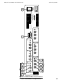
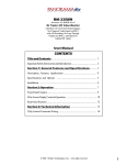
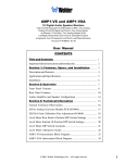
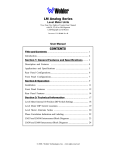
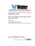
1
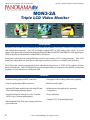
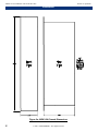
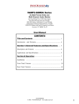
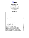
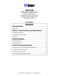
MON3-2A
2U Triple LCD Video Monitor
With Analog Inputs and Loop-throughs,
Optional Additional Input Sections, and
Optional SDI Inputs and Outputs
with Converted to Analog Output
Document P/N 821521 Rev-B.5
User Manual
CONTENTS
Title and Contents ...................................................... 1
Introduction .................................................................................. 2
Section 1: General Features and Specifications ... 3
General Description and Features ................................................ 4
Applications and General Specifications ...................................... 5
Section 2: Operation
................................................. 7
Installation ................................................................................... 9
Front Panel Features .................................................................... 10
Rear Panel Features ..................................................................... 12
Section 3: Technical Information ............................ 17
Tally Control Connector Wiring ................................................... 18
MSDI-1 SDI Option Field Upgrade .............................................. 20
1
Important Safety Instructions
1)
Read these instructions.
2)
Keep these instructions.
3)
Heed all warnings.
4)
Follow all instructions.
5)
Do not use this apparatus near water.
6)
Clean only with dry cloth.
7)
Do not block any ventilation openings. Install in accordance with the manufacturer's instructions.
8)
Do not install near any heat source such as radiators, heat registers, stoves, or other apparatus (including
amplifiers) that produce heat.
9)
Do not defeat the safety purpose of the polarized or grounding-type plug. A polarized plug has two blades
with one wider than the other. A grounding type plug has two blades and a third grounding prong. The
wide blade or the third prong are provided for your safety. If the provided plug does not fit into your outlet,
consult an electrician for replacement of the obsolete outlet.
10) Protect the power cord from being walked on or pinched, particularly at plugs convenience receptacles
and the point where they exit from the apparatus.
11) Only use attachments/accessories specified by the manufacturer.
12) Use only with the cart stand, tripod, bracket, or table specified by the manufacturer, or sold with the
apparatus. When a cart is used, use caution when moving the cart/apparatus combination to avoid injury
from tip-over.
13) Unplug this apparatus during lightning storms or when unused for long periods of time.
14) Refer all servicing to qualified service personnel. Servicing is required when the apparatus has been
damaged in any way, such as when power-supply cord or plug is damaged, liquid has been spilled or
objects have fallen into the apparatus, the apparatus has been exposed to rain or moisture, does not
operate normally, or has been dropped.
15) Do not expose this apparatus to rain or moisture.
16) The apparatus shall be connected to a mains socket outlet with a protective earthing connection.
CAUTION!
In products featuring an audio amplifier and speakers, the surface at the side of the
unit, where the audio amplifier heat sink is internally attached, may get very hot after
extended operation. When operating the unit excercise caution when touching this
surface and ensure that external materials which may be adversely affected by heat
are not in contact with it. There is a Hot Surface label (see diagram) attached to the
aforementioned surface of the product.
Introduction
Congratulations on your selection of a PANORAMAdtv product. We are confident it represents the best performance and value
available, and we guarantee your satisfaction with it.
If you have questions or comments you may contact us at:
Wohler Technologies, Inc.
31055 Huntwood Avenue
Hayward, CA 94544
Phone: (510) 870-0810
Fax: (510) 870-0811
US Toll-Free: 1-888-596-4537
www.panoramadtv.com
2
[email protected]
© 2007 Wohler Technologies, Inc. ALL rights reserved
MON3-2A User Manual P/N 821521 Rev-B.5
Sect. 1: General Features and Specifications
Section 1
General Features
and Specifications
Description
Features
Applications
Specifications
© 2001 PANORAMAdtv ALL rights reserved
3
MON3-2A User Manual P/N 821521 Rev-B.5
Section 1: General Features and Specifications
MON3-2A
Triple LCD Video Monitor
MON3-2A Front Panel
Description
The MON3-2A is a 2RU chassis containing three 4 inch Active Matrix TFT LCD’s. Each LCD is back lit with a
cold cathode fluorescent tube. The LCD can display standard NTSC or PAL analog video signals. A second
analog video input can be selected with the optional Analog B Board. SMPTE 259M/EBU601 serial digital inputs
(SDI) are displayed with installation of the MSDI-1 SDI option.
Front panel controls provide analog/SDI input selection and complete LCD viewing parameters. Each LCD
display has independent rear panel power and input termination switches for complete unit flexibility.
The LCD module circuitry automatically detects and indicates the presence of NTSC or PAL signals with front
panel LED indicators. Each LCD display has its own front panel trim pot controls for color, tint/hue, contrast and
brightness. Power indication is a front panel LED.
Features
• Standard Analog inputs on BNC connectors
• Front panel A/B switching with remote capability
• Video Loop-through on BNC connectors
• Red/Green tally lights
• Optional SDI input module with reclocking SDI and
converted analog monitoring outputs
• Minimal power dissipation (low operating
temperature)
• Front Panel trim pot controls for Color, Tint/Hue
(NTSC only), Contrast and Brightness
• Power indication
• Compact 2U, 9" deep and lightweight
• Dual Standard NTSC/PAL Auto-sensing with front
panel indication
4
© 2001 PANORAMAdtv ALL rights reserved
MON3-2A User Manual P/N 821521 Rev-B.5
Section 1: General Features and Specifications
Applications
The MON3-2A is ideally suited for monitoring of multiple video feeds in VTR bays, mobile production vehicles,
news and transmission control rooms, and duplication and post production applications. Designed and manufactured
in the U.S., the MON3-2A is backed by a strong warranty and a satisfaction guaranteed return policy.
General Specifications
Display Type:
TFT LCD Active Matrix
Display Area:
4 inches diagonal
Video Signal:
NTSC 525/60 or PAL 625/50
Auto-sensing. Analog and/or SDI
Operating
Tempurature:
0 to +40 degrees Celsius
Indicators:
Power LED, Display Tally LED's 1, 2, and
3, PAL/NTSC LED 1, 2, and 3
Connectors:
(Standard Unit)
Selectable 75 ohm Termination on BNC
Analog Video Input = 3 x BNC
Analog Video Loop-through = 3 x BNC
AC Power = IEC-320
Tally = Dsub 15-pin Female
Display Dot
Resolution:
480 (H) x 234 (V)
Dot Pitch:
0.118 (Width) x 0.362 (Height)
Back Light:
Built in Cold Cathode Fluorescent
Tube (25,000 min. average hours)
Dimensions
(WxLxH):
19 x 6.5 x 3.5 inches
(483 x 165 x 89 mm)
Display Controls:
Color, Tint/Hue, Brightness, and
Contrast
Weight:
10 lbs. (3.73 kg) Approximately
MON3-2A Rear Panel
3B
POWER SUPPLY
APPROVALS
POWER SUPPLY
IS UL
APPROVED
SEE SIDE FOR ADDITIONAL APPROVALS
120-240 VAC
50/60 Hz
60VA
CVBS
OUT
SDI
LOOP
2B
SDI
IN
CBAR
ON
PANORAMAdtv
711 Grandview Drive
South San Francisco, CA 94080
(650) 589 5676 FAX (650) 589 1355
CVBS
OUT
SDI
LOOP
1B
SDI
IN
CBAR
ON
CVBS
OUT
SDI
LOOP
SDI
IN
CBAR
ON
TALLY
SERIAL NUMBER
ON
TERM
ON
TERM
ON
TERM
OFF
LIFT
OFF
LIFT
OFF
LIFT
3A
IN
CVBS
LOOP
CVBS
2A
IN
CVBS
LOOP
CVBS
1A
IN
CVBS
LOOP
CVBS
MON3-2A Rear Panel
Available Options:
SDI Input Module (Field Retrofit) - one per channel
Additional Analog Input module - one per channel
Units are certified to meet, at time of manufacture, all currently applicable product safety and EMC requirements, such as those of
CE. 0 dbV ref. 0.775V RMS. Features and specifications subject to improvement without notice.
© 2001 PANORAMAdtv ALL rights reserved
5
MON3-2A User Manual P/N 821521 Rev-B.5
6
© 2001 PANORAMAdtv ALL rights reserved
MON3-2A User Manual P/N 821521 Rev-B.5
Section 2
Operation
Installation
Front Panel Features
Rear Panel Features
© 2001 PANORAMAdtv ALL rights reserved
7
MON3-2A User Manual P/N 821521 Rev-B.5
Section 2: Operation
Installation
Figure-2a: MON3-2A Chassis Dimensions
8
© 2001 PANORAMAdtv ALL rights reserved
MON3-2A User Manual P/N 821521 Rev-B.5
Section 2: Operation
Installation
Unpacking
Unpack the MON3-2A from the shipping container and inspect all articles for shipping damage. If you find any
damage, notify the shipping carrier immediately for claims adjustments. Compare the shipping box contents to
the packing slip. Contact PANORAMAdtv sales representative if there are any unexplained shortages.
Power Requirements
The MON3-2A is equipped with a world standard power supply that is capable of operating on 90-264 VAC @
50-60 Hz. Power consumption is 12 watts, standard and 21 watts when all three MSDI SDI options are
installed.
Power Supply LED Indication: The green Power LED at the center of the front panel glows green to indicate the
MON3-2A is connected to mains power and an operating voltage is present. Individual displays are turned on or
off from their respective ON/OFF switches located on the unit rear.
Cooling and Airflow
No special physical mounting considerations are necessary regarding unit heat dissipation except under adverse
conditions. Provided the ambient temperature inside the mounting enclosure does not exceed 40 degrees Celsius
(104 degrees Fahrenheit), adjacent devices can be rack mounted (or stacked) in proximity to the MON3-2A. If the
above temperature is exceeded, allow a 1RU (1.75”/25mm) space above and below the unit for air circulation.
Rack Mounting
The MON3-2A rack mounts in a standard specification rack and needs 2RU of space. (See Figure-2a, page 8 for
unit dimensions.) Allow sufficient space at the unit rear for connector and cable clearance (approximately 4”/
102mm). The MON3-2A weighs approximately 10 pounds (3.73 kg) and rack mounts from the front panel support
rails. Rear support is not required.
LCD Monitor Viewing Position: To obtain the best operator’s viewing angle, mount the MON3-2A as nearly
“straight on” to the operator’s position as possible (0 degrees left/right or up/down). Good image quality is
assured if viewing angles are between +/- 45 degrees from the center axis in the horizontal plane (left/right). In the
vertical axis, good image quality is obtained between 10 degrees looking down and 30 degrees looking up. Due to
the nature of LCD’s, there are certain anomalies, which can cause the displayed video to appear incorrect. If the
viewer is outside the optimal LCD display viewing range, the contrast ratio, brightness, and color saturation will
not be or may not appear to be, a true representation of the displayed video. Additional anomalies such as loss of
resolution, apparent reversed video effect, and frame/field strobe effect with the CCFT backlight may also be
observed. The LCD used in the MON3-2A is optimized for viewing from the 12 o’clock position. That is from
approximately eye height and upwards. Typically, the MON3-2A is mounted at eye height and viewed by looking
straight into the display. Going beyond the specified viewing area can cause anomalies as mentioned above.
NOTE: In PAL mode operation, the LCD driver discards every seventh line of active video so an entire video
frame fits within the display screen. This is normal with most LCD’s currently on the market.
General Installation Recommendations
EMI Interference: To ensure EMI interference is kept to a minimum, terminate all unused connectors.
Recommended Cables: Recommended cable type for Analog or SDI signals is: Belden 1694A.
Static Discharge: As with most electronic equipment, static discharges can damage components within the unit.
Take precautions to ensure your installation environment is not subject to static discharges.
© 2001 PANORAMAdtv ALL rights reserved
9
MON3-2A User Manual P/N 821521 Rev-B.5
Section 2: Operation
Front Panel Features
Please refer to Figure-2b on the following page to familiarize yourself with the front panel features of the MON32A unit. The following sections describe these features and are referenced, by number, to Figure-2b.
Note: Descriptions of items 2 through 6 apply to each one of the three monitor sections (1 - 3).
1
Power Indication - Green LED
The Power Indicator glows green when mains power is connected to the MON3-2A. Individual
display power switches (Item E, page 12), located on the rear panel control the on/off operation of each of
the three associated displays.
2
LCD Video Monitor - TFT Screen
View input video sources here. Select source inputs by setting the Input (I/P) Selector Switch (Item 5,
below) to the desired input. Screen image parameters are adjustable by four manual controls (Item 3,
below).
3
LCD Video Monitor Display Controls - Rotary Trim Pots
Each LCD video monitor can be adjusted separately using these four image controls:
• TINT - Tint; adjust for desired image color hue (NTSC only).
• CHROMA - Color Saturation; adjust for desired amount of image color saturation.
• BRIGHT - Brightness; adjust for desired screen brightness.
• CONT - Contrast; Adjust for desired image scene dark-to-bright contrast.
4
PAL/NTSC Indication - Yellow LED
This indicator shows the detected signal type connected to the CVBS input connector. This LED
glows yellow to indicate a PAL encoded signal is connected. This LED remains dark to indicate an
NTSC signal is connected.
5
Input (I/P) Selection - Toggle Switch (MSDI-1 SDI Option)
This switch selects analog composite video (CVBS) or the SDI digital component video input
signals connected to the rear panel. (SDI sources require the MSDI-1 SDI option.) The Input (I/P)
Selector Switch selects these signals according to the following switch positions:
• UP (B): SDI digital component signal.
• DOWN (A): CVBS analog composite signal.
6
Tally Indication - Tri-color LED
This tri-color LED can glow red, green, or yellow to indicate tally status associated with the
signal displayed. Refer to page 18 for tally connection details.
7
Video Section Label - Blank
Use these blank areas to apply labels or write in names for each of three video control sections applicable to your
needs.
10
© 2001 PANORAMAdtv ALL rights reserved
MON3-2A User Manual P/N 821521 Rev-B.5
Section 2: Operation
Figure-2b: MON3-2A Front Panel Features
© 2001 PANORAMAdtv ALL rights reserved
11
Section 2: Operation
MON3-2A User Manual P/N 821521 Rev-B.5
Rear Panel Features
Please refer to Figure-2c on the following page to familiarize yourself with the rear panel features of the MON32A unit. The following sections describe these features and are referenced, by letter, to Figure-2c.
Note: The descriptions below apply to each one of the three monitor sections. Items F, G, H, and I apply only to
units configured with the MSDI-1 SDI option (factory installed or field upgraded).
A Power - IEC-320 Connector
Attach a standard IEC-320 power cord between this connector and mains power. Τhe front panel Power
LED will glow green to indicate that an operating voltage is present.
B In CVBS - BNC Connector
Connect analog CVBS video signals here. NTSC or PAL standards are accommodated automatically.
NOTE: Use the front panel Input (I/P) Selector Switch to select analog or option inputs: To select a CVBS
source place the Input Selector Switch in the DOWN (A) position. This switch position also enables input
video selections from the Remote Source Select Control connector, if installed.
C Loop CVBS - BNC Connector
Signal through connections to down-stream equipment are supplied here. If you supply down-stream
equipment from this connector, ensure you set the TERM/LIFT toggle switch (Item D) to the LIFT (DOWN)
position. If no other equipment is connected via this connector, set the TERM/LIFT switch to the TERM
(UP) position.
D Term/Lift - Toggle Switch
This switch terminates the “IN CVBS” connector as required by your configuration. Placing this switch
to the TERM (up) position inserts a 75Ω termination impedance in the video signal. This is the required
position for correct signal levels when down-stream equipment is not connected to the “LOOP CVBS”
connector (Item C).
E On/Off - Toggle Switch
Individual monitor power switch. Use this switch to turn the power on or off to the associated monitor.
F SDI In - BNC Connector (MSDI-1 SDI Option)
Connect SMPTE 259M/EBU601 SDI signals here. This connector is terminated at 75Ω. (MSDI-1 SDI
option required.)
NOTE: Use the front panel Input (I/P) Selector Switch (Item 5, page 10) to select analog or digital inputs:
To select an SDI source place the Input Selector Switch in the UP (B) position.
G SDI Loop - BNC Connector (MSDI-1 SDI Option)
Signal through connections to down-stream equipment are supplied here. This connector supplies a buffered
replica of the input signal. (MSDI-1 SDI option required.)
(Continued)
12
© 2001 PANORAMAdtv ALL rights reserved
Section 2: Operation
MON3-2A User Manual P/N 821521 Rev-B.5
POWER SUPPLY
APPROVALS
POWER SUPPLY
IS UL
APPROVED
SEE SIDE FOR ADDITIONAL APPROVALS
120-240 VAC
50/60 Hz
60VA
A
PANORAMAdtv
711 Grandview Drive
South San Francisco, CA 94080
(650) 589 5676 FAX (650) 589 1355
3B
CBAR
ON
CVBS
OUT
SDI
LOOP
TALLY
SERIAL NUMBER
J
SDI
IN
ON
LIFT
TERM
IN
CVBS
CBAR
ON
2B
OFF
3A
CVBS
OUT
LOOP
CVBS
SDI
LOOP
ON
LIFT
TERM
SDI
IN
OFF
2A
IN
CVBS
1B
CBAR
ON
I
CVBS
OUT
LOOP
CVBS
SDI
IN
13
© 2001 PANORAMAdtv ALL rights reserved
3 Places
TERM
IN
CVBS
D B C
LOOP
CVBS
H G F
ON
LIFT
SDI
LOOP
OFF
1A
E
3 Places
Figure-2c: MON3-2A Rear Panel Features
Section 2: Operation
MON3-2A User Manual P/N 821521 Rev-B.5
Rear Panel Features
(Continued)
H
CVBS Out - BNC Connector (MSDI-1 SDI Option)
This connector supplies an analog CVBS encoded signal derived from the SDI input. Automatic standards
sensing is accomplished by detecting 525 or 625 line signals. 525 line SDI input signals are encoded as an
NTSC output. 625 line SDI input signals are encoded as a PAL output. (MSDI-1 SDI option is required.)
I
CBAR On - Toggle Switch (MSDI-1 SDI Option)
This switch controls a color bar generator associated with each monitor. To view the input signal, place
this switch in the DOWN position. To activate the color bar generator, place this switch to the CBAR ON
(UP) position. (MSDI-1 SDI option is required.)
Note: An active SDI input must be present for the color bars to function.
J
Tally Control - DB-25 Connector
This 25 pin sub-miniature female “D” connector allows you to tally individual monitor front panel Tally
indicators. Full connection instructions are described on page 18.
14
© 2001 PANORAMAdtv ALL rights reserved
Section 2: Operation
MON3-2A User Manual P/N 821521 Rev-B.5
POWER SUPPLY
APPROVALS
POWER SUPPLY
IS UL
APPROVED
SEE SIDE FOR ADDITIONAL APPROVALS
120-240 VAC
50/60 Hz
60VA
A
PANORAMAdtv
711 Grandview Drive
South San Francisco, CA 94080
(650) 589 5676 FAX (650) 589 1355
3B
CBAR
ON
CVBS
OUT
SDI
LOOP
TALLY
SERIAL NUMBER
J
SDI
IN
ON
LIFT
TERM
IN
CVBS
CBAR
ON
2B
OFF
3A
CVBS
OUT
LOOP
CVBS
SDI
LOOP
ON
LIFT
TERM
SDI
IN
OFF
2A
IN
CVBS
1B
CBAR
ON
I
CVBS
OUT
LOOP
CVBS
SDI
IN
15
© 2001 PANORAMAdtv ALL rights reserved
3 Places
TERM
IN
CVBS
D B C
LOOP
CVBS
H G F
ON
LIFT
SDI
LOOP
OFF
1A
E
3 Places
Figure-2c: MON3-2A Rear Panel Features
MON3-2A User Manual P/N 821521 Rev-B.5
16
© 2001 PANORAMAdtv ALL rights reserved
Section 2: Operation
MON3-2A User Manual P/N 821521 Rev-B.5
Section 3
Technical Information
Tally Control
Connector Wiring
MSDI-1 SDI Option
Field Upgrade Instructions
© 2001 PANORAMAdtv ALL rights reserved
17
MON3-2A User Manual P/N 821521 Rev-B.5
Section 3: Technical Information
Tally Control Connector Wiring
A front panel dual color (red and green) tally LED is associated with each LCD monitor. Interface is provided to
the LEDs via the Tally Control Connector. Tri-color (red, green, and yellow) tally indications are possible by
activating the red and green LED sections simultaneously. For connection details, see Figure-3a below .
MON3-2A Rear Panel
Figure-3a: MON3-2A Tally Control Connector Pin Function Table
Figure 3-b, on the facing page, shows sample tally connection configurations. You can operate the Tally LEDs by
numerous methods. The two tutorial examples showing isolated and non-isolated activation are illustrated to show
basic operation. Although switches are employed in these examples, the LEDs interface with TTL levels. You can
design illumination circuits as shown, by using TTL buffers, or by using transistors as switches.
The Tally indicators are capable of displaying three colors. Illuminating the red or green LEDs separately will result
in that tally color. Illuminate the red and green LEDs simultaneously to achieve a yellow tally.
Isolated
Operating the Tally LEDs in an isolated configuration requires an external (customer provided) power supply and
tally system. If your facility currently has a tally system with companion power source, use this method to integrate
the MON3-2A tallies with your existing tally matrix.
NOTE: Ensure the LED power supply provides +5 to +12VDC.
Non-Isolated
Operating the Tally LEDs in the non-isolated configuration uses the MON3-2A internal power supply to provide the
tally LED voltage. Connect your tally closures as shown in Figure-3b to the respective MON3-2A tally connections.
18
© 2001 PANORAMAdtv ALL rights reserved
MON3-2A User Manual P/N 821521 Rev-B.5
Section 3: Technical Information
Tally Control Connector Wiring
MON3-2A Tally Circuit
Figure-3b: MON3-2A Sample Tally Connections
© 2001 PANORAMAdtv ALL rights reserved
19
MON3-2A User Manual P/N 821521 Rev-B.5
Section 3: Technical Information
MSDI-1 SDI Option Field Upgrade
This section explains the procedures for field upgrading your unit for the MSDI-4 SDI option.
1) We advise you to work with the unit on a clean, well lighted work bench.
2) Ensure the MON3-2A is disconnected from the power mains.
3) Remove top cover. Retain screws for later reassembly.
4) Remove the blanking plugs from the BNC connector holes. (Rear panel sections 1B through 4B.)
5) Remove the flat ribbon cable from the rear I/O PC board. (Horizontal removal/insertion.)
6) Install the option kit-supplied flat ribbon connector into the connector previously vacated in Step 5.
7) Install the option kit-supplied power harness to the rear I/O PC board 4 pin header associated with the position
where this particular MSDI-1 option will be installed. (J22, J23, J24, or J25.) The RED wires are referenced
to the + symbol silk-screened on the circuit board.
8) Insert the flat ribbon into the rear (horizontal) flat ribbon connector on the MSDI-4 board.
9) Insert the flat ribbon cable to the front LCD into the inboard (vertical) flat ribbon connector on the MSDI-4 board.
10) Attach the MSDI-4 to the rear panel using the supplied nuts.
11) Attach the power harness to the 4 pin header on the MSDI-4. The RED wires go towards the marking “+12V.”
12) Double check all wiring and connections.
13) Connect an SDI signal to the SDI input and set the front panel Input (I/P) Selector Switch (Item 5 on page 10)
to the UP (B) position. Connect mains power to the unit and confirm operation.
14) Remove Mains power from the unit and repeat steps 4 through 13 for each monitor section receiving the option
installation. (We suggest each monitor section be individually installed and tested.)
15) Replace cover and return to service.
20
© 2001 PANORAMAdtv ALL rights reserved
MON3-2A User Manual P/N 821521 Rev-B.5
Wohler Technologies, Inc.
31055 Huntwood Avenue
Hayward, CA 94544
Phone: (510) 870-0810
Fax: (510) 870-0811
US Toll-Free: 1-888-596-4537
www.panoramadtv.com
[email protected]
© 2001 PANORAMAdtv ALL rights reserved
27
MON3-2A User Manual P/N 821521 Rev-B.5
Panorama DTV
Wohler713
Technologies,
Grandview Drive Inc.
31055
Huntwood
South San
Francisco,Avenue
CA 94080
Hayward,
CA
94544
650 589-5676 Fax: 650 589-1355
Phone: (510)
Fax: (510) 870-0811
web:870-0810
www.panoramadtv.com
US Toll-Free:
1-888-596-4537
e-mail:
[email protected]
www.panoramadtv.com [email protected]
28
© 2001 PANORAMAdtv ALL rights reserved