1
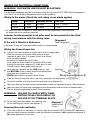
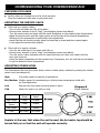
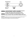
Powerstream-Eco
REDRING POWERSTREAM-ECO
UNVENTED INSTANTANEOUS
WATER HEATER
Installation and User Guide
IMPORTANT:
This booklet should be left with the user after
installation and demonstration.
It should be kept in a safe place, as you may need to
refer to it for general instructions or future
maintenance
CONTENTS
Section
Page
Introduction . . . . . . . . . . . . . . . . . . . . . . . . . . . . . . . . . . . . . . . . . . . . . . . . . . . . .
2
Redring After Sales Service . . . . . . . . . . . . . . . . . . . . . . . . . . . . . . . . . . . . . . . . . . .
2
Important Safety Information . . . . . . . . . . . . . . . . . . . . . . . . . . . . . . . . . . . . . . . . .
3
How to install your Powerstream-Eco . . . . . . . . . . . . . . . . . . . . . . . . . . . . . . . . . . . .
4
Commissioning your Powerstream-Eco . . . . . . . . . . . . . . . . . . . . . . . . . . . . . . . . . . .
9
How to use your Powerstream-Eco . . . . . . . . . . . . . . . . . . . . . . . . . . . . . . . . . . . . .
10
What to do if things go wrong (1) Self Help . . . . . . . . . . . . . . . . . . . . . . . . . . . . . . .
12
What to do if things go wrong (2) Professional Service . . . . . . . . . . . . . . . . . . . . . . .
13
How your Powerstream-Eco Works . . . . . . . . . . . . . . . . . . . . . . . . . . . . . . . . . . . . .
14
Additional Accessories and Common Spare Parts . . . . . . . . . . . . . . . . . . . . . . . . . . . .
15
Technical Information . . . . . . . . . . . . . . . . . . . . . . . . . . . . . . . . . . . . . . . . . . . . . . .
15
Guarantee and Contact Details . . . . . . . . . . . . . . . . . . . . . . . . . . . . . . . . . . . . . . . .
16
INTRODUCTION
Thank you for purchasing a quality Redring Powerstream-Eco manufactured in England.
To enjoy your new unit at its best, please take time to read this manual thoroughly to
familiarise yourself with all instructions, BEFORE beginning installation.
If you experience any difficulty with the installation or operation of your new
water heater, then please refer to the “What to do if things go wrong” section
in this manual before contacting us.
REDRING AFTER SALES SERVICE
We offer a technical advisory service on the telephone to installers and other customers with
problems in the field.
RING 0844 372 7766 (UK ONLY)
RING YOUR LOCAL DEALER (Export Variants)
Or alternatively email us on:
[email protected]
Remember to quote the exact type of unit, as written on the front of the unit and on this leaflet.
The model and serial number are located on the bottom face of the unit.
Make a note of those numbers here, and be sure to quote them if you call for advice.
Model Number: _ _ _ _ _ _ _ _ _ _ _ Serial Number: _ _ _ _ _ _ _ _ _ _ _ _
Note: You may be charged for a service call if you do not have the serial number.
2
IMPORTANT SAFETY INFORMATION
Your Powerstream-Eco has been designed for convenience, economy
and safety of use, provided that it is installed, used and maintained in
good working order and in accordance with our instructions and
recommendations.
All wiring and installation must be supervised by a suitably
qualified person.
THIS APPLIANCE MUST BE EARTHED.
The installation must be in accordance with the current edition of
BS.7671 (the “IEE Wiring Regulations”) and “Part P” of the “Building
Regulations” in force at the time of installation. Installations outside
England and Wales must also conform to any local regulations in effect.
This appliance is intended to be permanently connected to the fixed
electrical wiring of the mains supply with its own dedicated supply.
Ensure that the mains water supply meets the requirements listed.
This appliance must NOT be fitted where it may be subjected to freezing
conditions. DO NOT switch the appliance on if you suspect it of being
frozen. Wait until you are sure it has thawed out.
The unit MUST NOT be mounted upside down (diagram 1b).
The unit MUST NOT be fitted to any type of THERMOSTATIC
mixer valve or tap.
If a non-return valve is fitted in the Inlet feed to the unit, then the
installation should also include a 3.5 BAR Pressure Reducing Valve and a
6 BAR Pressure Relief (Expansion) Valve.
Isolate the mains electrical and water supply before removing
the front cover of the appliance.
THIS APPLIANCE CAN BE USED BY CHILDREN AGED FROM 8
YEARS AND ABOVE AND PERSONS WITH REDUCED PHYSICAL,
SENSORY OR MENTAL CAPABILITIES, OR LACK OF EXPERIENCE
AND KNOWLEDGE IF THEY HAVE BEEN GIVEN SUPERVISION
OR INSTRUCTION CONCERNING USE OF THE APPLIANCE
IN A SAFE WAY AND UNDERSTAND THE HAZARDS INVOLVED.
CHILDREN SHALL NOT PLAY WITH THE APPLIANCE.
CLEANING AND USER MAINTENANCE SHALL NOT
BE MADE BY CHILDREN.
3
HOW TO INSTALL YOUR POWERSTREAM-ECO
WARNING: ALL WIRING AND INSTALLATION MUST BE SUPERVISED BY A
SUITABLY QUALIFIED PERSON.
WARNING: DO NOT INSTALL THIS UNIT WHERE IT MAY BE SUBJECTED TO
FREEZING CONDITIONS.
Diagram 1a
Examples of fitted units
The Powerstream-Eco is recommended to supply a
MAXIMUM of two washbasins (see diagram 1a)
OR a washbasin and shower (see diagram 4b)
If the Powerstream-Eco is connected to a mixer tap
then only NON-Thermostatic types should be used
(water mixes at the outlet pipe only).
The Powerstream-Eco is NOT to be fitted to a
bath or kitchen sink other than for hand-washing purposes.
(See Guarantee exclusions on page 16 and
product flow rate tables on page 14).
The unit MUST NOT be mounted upside down (diagram 1b).
Diagram 1b
BEFORE YOU START
Acceptable unit orientation
Check that the mains electric is capable of supplying the required current.
See the rating plate for current requirements.
Check the pressure of the main water supply.
To operate correctly, the unit requires the following running pressures.
Check the rating plate to see which applies:Dynamic Water Pressure
Model
Basin
Shower
Minimum
Maximum
Minimum
Maximum
Up to 9.5kW
10 psi (0.7 bar)
(69 kPa)
150 psi (10.3 bar)
(1035 kPa)
15 psi (1.1 bar)
(103 kPa)
150 psi (10.3 bar)
(1035 kPa)
Up to 10.8kW
15 psi (1.1 bar)
(103 kPa)
150 psi (10.3 bar)
(1035 kPa)
20 psi (1.4 bar)
(138 kPa)
150 psi (10.3 bar)
(1035 kPa)
4
FIXING THE UNIT TO THE WALL
Deciding the position
If being used in a public place, position the unit out of reach to discourage vandalism.
Fit the unit onto a flat piece of wall, well away from any potential splashes of water or spray.
Position the unit either upright or lengthways (diagram 1a/b), whichever is most convenient for
plumbing and wiring.
IMPORTANT : TO MAINTAIN THE INTEGRITY OF THE IPX4 PROTECTION
RATING, THE UNIT MUST NOT BE MOUNTED UPSIDE DOWN
(DIAGRAM 1B)
Remember to keep the lengths of hot water pipe to a minimum in order to save energy.
If the unit is to supply a basin, you can fit it either above or below the basin.
Deciding the wiring route
You have a choice of whether to feed the electric cable
through the side or through the back of the unit.
If it going through the side of the unit, cut out the
plastic lug to expose the grommet (diagram 2).
If is going through the back of the unit, cut through the
grommet on the backplate with a sharp knife (Take Care!).
Make sure you do not remove the grommet from the
backplate (diagram 3).
Feed the cable through the grommet before you fix the
unit to the wall.
Diagram 2
Lug cut out
Fixing to the wall
Undo the retaining nuts and take the front cover off the unit.
Hold the backplate in position against the wall whilst you mark the four fixing holes.
Drill the holes and fix the unit to the wall using the screws supplied.
Diagram 3
Back of unit
5
Plumbing the unit
WARNING: IF A NON RETURN VALVE IS FITTED IN THE INLET FEED TO THE
UNIT, THEN THE INSTALLATION SHOULD ALSO INCLUDE A
3.5 BAR PRESSURE REDUCING VALVE AND A
6 BAR PRESSURE RELIEF (EXPANSION) VALVE
Diagram 4a
Plumbing with
Non-Return
Valve
Diagram 4b
Unit serving
Basin and
shower
WARNING: ENSURE THAT THE MAINS WATER SUPPLY MEETS THE
REQUIREMENTS LISTED ON PAGE 4 BEFORE CONTINUING
WITH INSTALLATION.
WARNING: BEFORE CONNECTING THE PIPE WORK TO THE
POWERSTREAM-ECO, ENSURE THAT THE PIPE WORK IS
FULLY FLUSHED OUT.
6
Fitting the pipes
The unit should be connected directly to the main cold water supply.
We recommend that you use Ø15mm copper or stainless steel pipe for the inlet and outlet
connections. (See addendum sheet for local installation requirements).
Use PTFE tape for making screw joints. Do not use a jointing compound.
Remember to keep the hot water pipe runs as short as possible.
If the unit is to supply more than one basin outlet, the height should be the same at each outlet
if they are to be used at the same time. If not, one outlet will take all the water.
In some cases, it may be worth fitting a second unit.
When the pipework has been plumbed in, flush it through with water before you connect the
unit, to remove any swarf or loose particles.
Connecting the unit to the pipes
The inlet and outlet are clearly marked on the unit.
UK models have Ø15mm straight shank connections.
Other export models are fitted with ½” NPT connections.
The unit comes with a service valve (diagram 5) which should be fitted on the inlet of the unit.
Models have either Ø15mm straight shanks or ½” NPT connections. Check to see which applies.
The valve can be used to turn off the water supply to the unit if it needs servicing, or to reduce
the main supply flow if it is too high (see “Powerstream-Eco commissioning” section on page 9).
Fitting the attachments
If the unit is to supply a shower, you will also need a “Redring Mixer Unit”. Available in
chrome/white finish and suitable for surface or concealed pipe entry (see page 15 for details).
If the unit is to supply a shower, and the shower handset can reach water in a bath or basin, you
must fit a vacuum breaker to comply with Water By-laws.
Alternatively, use the hose-retaining feature built into the soapdish.
Because water can sometimes seep through, you should position the vacuum breaker where
dripping will not do any damage.
If the unit is to supply a basin or two basins, we recommend that you use
“¼ turn lever control spray taps” (see page 15 for details).
Diagram 5
Service Valve supplied with:
UK Models
Export Models
7
MAKING THE ELECTRICAL CONNECTIONS
WARNING: THIS WATER HEATER MUST BE EARTHED.
The electrical installation must be in accordance with the current BS.7671 (IEEE Wiring Regulations)
and “Part P” of the Building Regulations and/or local regulations
Wiring to the mains (Check the unit rating to see which applies)
Rating
Fuse/MCB
Isolating Switch
Cable Size
9.5 kW
40 amps
40 amps
6 mm² / 10 mm² *
10.8 kW
45 amps
45 amps
10 mm²
* For cable runs over 10 metres or where cable is not flat clipped and surface mounted,
the larger size is the minimum required.
A means for disconnection in all poles must be incorporated in the fixed
wiring in accordance with the wiring rules.
Diagram 6
If the unit is fitted in a Bathroom:
Cable Termination
A standard 45 amp cord operated isolator switch is recommended.
Wiring the Powerstream-Eco
The unit has been designed to accept up to 16mm² supply cable.
It will be necessary to cut the rubber entry grommet
(diagram 6, point X to X) to enable 10mm² and 16mm²
to be correctly installed.
No cutting is required for 6mm² cable.
In all cases the outer sheath of the cable MUST project
through the grommet (diagram 6), if side entry is used.
This will prevent water getting into the unit.
Strip back the insulation on the LIVE (brown or red)
and NEUTRAL (blue or black) mains wires about 8mm.
Strip back any insulation on the
EARTH (green/yellow or green) about 20mm.
Feed the cable through the side or rear entry grommets, as appropriate.
Connect the cables to the terminal block and earth stud (diagram 6)
Make sure that the live and neutral terminal block screws are tightened securely (1Nm minimum)
Make sure that the earth wire is wrapped around its terminal stud and into the saddle washer.
The nut should be tightened securely (2Nm minimum).
WARNING: FAILURE TO COMPLY WITH THESE
INSTRUCTIONS COULD RESULT IN
FAILURE OF THE TERMINAL BLOCK
Fit the front cover and tighten the retaining nuts.
Fit the retaining nut covers (see diagram 7).
Ensuring the earth continuity
Diagram 7
Retaining Nut
Covers
If the unit is fitted in a bathroom, to conform with the current BS.7671 (formally IEE regulations),
the units earth continuity conductor must be effectively connected to ALL exposed metal parts of
ALL other appliances in the room.
8
COMMISSIONING YOUR POWERSTREAM-ECO
CHECKING FOR LEAKS
Let the water run through the unit for a few seconds.
Close the outlet and check that no pipe joints leak.
ADJUSTING THE SERVICE VALVE
If the unit is to supply a basin,
- Turn on the hot water tap fully at the basin.
- Ensure power selector is set to “High” (see adjusting power level below).
- Turn the service valve on slowly until the neon illuminates on the product (max temperature).
- Adjust the service valve until the water comes out of the tap at the required temperature.
Allowing for the temperature to settle after each adjustment.
- check that the unit works correctly when the basin tap is closed and then opened again:
if not, adjust the service valve slightly.
If the unit is to supply a shower,
- Turn the hot water tap on the mixer unit fully on.
- Ensure power selector is set to “High” (see adjusting power level below)
- Turn the service valve clockwise until the neon light goes out, then turn it back until the
neon just comes on.
- check the water temperature at the handset and, if necessary, turn the cold tap on and adjust
to get the desired shower temperature.
ADJUSTING POWER LEVEL
The Powerstream-Eco has four power levels, shown in table below, selected by rotating the central
power knob (see diagram 8).
High
Full power used for majority of applications.
Eco/Medium Medium power for handwashing or offering lower temperature outlet with
no flow adjustment.
Low
Summer use only where incoming water is warm.
Cold
Allows the unit to run with no heat.
9.5kW
Model
10.8kW
Model
High Power
9.5kW
10.8kW
Eco / Medium
Power
5.4kW
6.0kW
Low Power
4.1kW
4.8kW
Cold
No Power
No Power
Diagram 8
Power Selection
Explain to the user that when the unit is used, the hot water tap should be
turned fully on so that the unit will operate correctly.
9
HOW TO USE YOUR POWERSTREAM-ECO
WARNING: DO NOT USE THE UNIT IF YOU THINK IT MAY BE FROZEN,
AS THIS COULD RESULT IN SERIOUS DAMAGE TO THE UNIT.
WAIT UNTIL YOU ARE SURE THAT IT HAS COMPLETELY
THAWED OUT BEFORE YOU SWITCH ON.
Basin
Check that the power is switched on at the mains isolator switch.
Turn on the hot water tap FULLY. If you do not turn the tap on fully, you will find that the
temperature of the water will vary. The hot water temperature will have been set using the
service valve (diagram 5). See “Selecting my power level” section
If the unit has been used recently, run the water through for a few seconds to let the
temperature settle down, we advise you DO NOT enter the water flow during this time.
WARNING: YOU MAY INITIALLY GET A SHORT BURST OF VERY HOT
WATER FROM THE UNIT.
If a second tap connected to the unit is also turned on, the hot water will be shared between the
two and so the flow will drop.
When you have finished do not switch off the power if you are going to use the unit again shortly
Shower
Check that the power is switched on at the mains local isolator switch.
Turn on the hot (or “flow”) tap FULLY (diagram 9). Ensure unit is set to “High” setting.
If the unit has been used recently, run the water through for approximately 20 seconds to let the
temperature settle down, we advise you DO NOT enter the water flow during this time.
WARNING: YOU MAY INITIALLY GET A SHORT BURST OF
VERY HOT WATER FROM THE UNIT.
Turn on the cold (or “temperature”) tap, if necessary, to adjust the temperature of the water.
Make sure that no other outlets connected to the unit are used whilst you are in the shower, or
the water flow will drop suddenly.
When you have finished do not switch off the power if you are going to use the unit again shortly
It is important to clean the shower handset regularly (see page 11).
In order for the Powerstream-Eco to function correctly, the “Redring Mixer Kit” must be used.
The kit, Cat No. 85-793620, comes complete with full accessories including a 3 position
multi-function shower handset.
SELECTING POWER LEVEL
The Powerstream-Eco has four power levels to choose from changing these allows the level of heat
to be changed in discreet steps. The user can set these easily by rotating the central knob to the
desired setting (see diagram 8). In general, the lower the power level is the lower the flow rate will
be, to achieve the same temperature. The control can be set up using the High setting and then the
temperature reduced by selecting a lower power level i.e. Set unit up for showering and then select
Eco/medium when using the unit to wash your hands.
CAUTION: The flow switch built into the Powerstream-Eco will switch off the heat if the flow rate is
set too low. This will be indicated by the neon light going out.
10
Diagram 9
Mixer Units
WARNING: YOU MUST REGULARLY INSPECT THE SHOWER HOSE FOR
WEAR AND DAMAGE. REPLACE IF NECESSARY,
OR EVERY TWO YEARS, WITH OUR APPROVED PART.
WARNING: IN ORDER TO MAINTAIN THE PERFORMANCE OF YOUR
UNIT, YOU MUST CLEAN THE SHOWER HANDSET REGULARLY.
All water contains particles of lime-scale, which build up in the shower handset and unit reducing the
performance.
It is therefore important to clean the shower handset by simply rubbing the rubber nozzles, or
soaking in proprietary lime-scale remover and rinsing thoroughly before use.
The frequency of this will depend on water hardness and experience.
11
WHAT TO DO IF THINGS GO WRONG (1)
SELF HELP
If the unit is not working satisfactorily, make the following checks before calling out the installer.
Any one of these adjustments could restore the performance.
Symptom
Cause
What to do
Little or no water flow.
The main water supply is turned
off.
Turn on the main supply fully at the
stop valve. Set up unit as per
commissioning instructions.
Cold water only
- neon light off.
The main water supply is not
turned on enough.
Power selector set to “cold”.
Turn on the main supply fully at the
stop valve.
Rotate power selector knob to high,
Eco or low.
Water too cold
- neon light on.
The water flow rate is too high.
Adjust the service valve (see page 9).
The inlet water temperature has
dropped.
Adjust the service valve (see page 9)
Power selector set too low.
Set power select to “High”.
For a shower, adjust the spray pattern
available on the multi-mode handset.
Rotate power selector to Higher
setting.
Water flow too low, or
temperature too high.
Water goes from hot
to cold.
Shower spray pattern
deteriorates.
The main water supply is too low
Increase the supply water flow.
Make sure that the service valve is
correctly adjusted.
The hot tap is not fully open.
Adjust the service valve so that the
water is at the right temperature with
the tap fully open (see page 9).
Power selector set too high.
Always turn the hot tap fully on.
Rotate power selector to lower setting
The water flow or pressure is too
low, and the thermal cut-out is
operating.
Increase the supply water flow
Make sure that the service valve is
correctly adjusted.
A second outlet has been turned
on.
Do not use the basin whilst using the
shower.
The shower handset is clogged.
Clean the handset using a descaling
solution if required (see page 11).
12
WHAT TO DO IF THINGS GO WRONG (2)
PROFESSIONAL SERVICE
If the previous “Self Help” checks fail to restore the performance, you should seek professional help.
The person who installed the Powerstream-Eco is probably the best one to investigate and correct it
and is certainly the person to contact if you have had a problem in the guarantee period.
The following additional checklist is provided for the benefit of the qualified service person.
WARNING: SWITCH OFF THE ELECTRICITY AT THE LOCAL ISOLATOR
BEFORE REMOVING THE COVER TO MAKE CHECKS
Symptom
Cause
What to do
Little or no water flows
- neon light off.
The water pressure is very low.
Use a pump to boost the supply from
a storage tank.
Cold water only
- neon light off.
The main water is connected to
the OUTLET of the unit.
Reconnect the main supply to the
INLET (marked in blue).
The water pressure is too low.
Use a pump to boost the supply from
a storage tank.
The thermal cut-out has
triggered.
Reset it by opening the unit and
pushing the button on the cut-out
(diagram 10). Before you do this you
must remove the cause of the
problem.
The flow switch is not working.
Contact Redring (see page 2).
The power select is set too low.
Change the power select to "High”
(diagram 8).
Water too cold
- neon light on.
One element is not working.
Switch off the electricity supply and
check the resistance of the elements.
You should get the following readings.
Loading (kW) Resistance (Ohms)
9.5
10.6 / 13.8 approx.
10.8
9.6 / 12.1 approx.
Water flow too low or
temperature too high.
The Power Supply Voltage has
dropped.
The heater should only draw the
following currents:
40 amps for the 9.5kW model
45 amps for the 10.8kW model
The service valve is fitted to the
OUTLET.
Fit the service valve to the INLET of
the unit.
There are constrictions in the
plumbing.
Check the plumbing. Only use PTFE
tape for making pipe joints.
Water goes from hot to The service valve is fitted to the
cold.
OUTLET.
13
Fit the service valve to the INLET of
the unit.
HOW YOUR POWERSTREAM-ECO WORKS
Water comes in through the inlet, via a flow switch.
The flow switch measures how much water is passing through the unit.
If it detects more than the preset level of:2.7 litres/minute for the 9.5kW model and 3.3 litres/minute for the 10.8kW.
The units heating elements are switched on. This is shown by the neon light glowing.
The water is heated instantly as it passes through the copper heat exchanger tube.
The temperature of the water coming out of the unit depends on:The temperature of the mains water supply
The water flow rate
The power consumption of the unit (power level selected)
The temperature of the main supply can vary from 5°C in winter up to about 20°C in summer, with
an average of about 12°C. The charts below show the water temperature (°C) you can expect from
the unit, at the different power settings for different flow rates in litres/minute.
9.5kW Powerstream-Eco
Flow rate
(litres/min.)
Power level
Summer temp °C
Winter temp °C
3.0
4.0
6.0
5.0
6.0
On average on “high”
High Eco Low High Eco Low High Eco Low (12°C main water supply
at 4 litres/minute)
65° 46° 40° 54° 39° 35° 43° 33° 30° an outlet temperature of
46°C will be achieved.
50° 31° 25° 39° 24° 20° 28° 18° 15°
10.8kW Powerstream-Eco
Flow rate
(litres/min.)
4.0
Power level
High Eco Low High Eco Low High Eco Low
Summer temp °C
58°
41°
37°
51°
37°
34°
46°
34° 31°
Winter temp °C
43°
26°
22°
36°
22°
19°
31°
19° 16°
On average on “high”
(12°C main water supply
at 5 litres/minute) an
outlet temperature of
43°C will be achieved.
The unit includes a dual thermal cut-out (diagram 10) which is attached to the heat exchanger tube.
It will switch off the heater elements if the water flow is reduced too much and the temperature goes
above a set limit.
The first stage cut-out is cyclic and will automatically
reset as the water temperature falls.
Diagram 10
The unit will then function normally again.
Thermal Cut-Out
The second stage cut-out when triggered needs to be re-set
manually inside the unit (diagram 10).
This cut-out will only operate in exceptional circumstances.
The unit can supply two outlets,
For example, a shower and a basin, or up to two basins
– but water from the unit will be shared between the outlets.
This is particularly important if a unit supplies a shower and a basin,
as the basin should not be used while someone is using the shower.
The unit is NOT to be fitted to a bath or kitchen sink other than for hand-washing purposes.
14
ADDITIONAL ACCESSORIES AND COMMON SPARE PARTS
Please Note :- The fitting of Spare Parts must be supervised by a suitably qualified person.
Chrome and White Shower Mixer Unit Complete with full accessories
Catalogue No.
Including 3 position multi-function handset
85-793620
¼ turn lever control spray tap for handwashing applications
85-793616
Thermal cut-out (manual reset)
93-793789
Printed front cover complete
93-794403
Control knob
93-794404
Screw cover set
93-794405
Flow switch assembly
93-794406
Heat exchanger 9.5kW 240V
93-794407
Heat exchanger 10.8kW 240V
93-794408
Power selector Assembly
93-794409
For further details, including a comprehensive list off accessories and spare parts,
Contact Redring After Sales Service (see page 2)
TECHNICAL INFORMATION
Diagram 11
Internal Details
Diagram 12
Circuit Diagram
15
GUARANTEE AND CONTACT DETAILS
GUARANTEE
Terms and Conditions for UK (outside UK contact your local distributor)
We guarantee this product for a period of 24 months from the date of purchase.
Within the guarantee period we will resolve, free of charge, any manufacturing defects in the product
resulting from faulty workmanship or material on condition that:a) The product has been correctly installed and commissioned in accordance with our instructions and
is being used on the supply circuit or voltage printed on the rating plate.
b) The product has been used in accordance with these instructions and has not been tampered with
or otherwise subject to misuse, neglect or accident.
c) The product has not been taken apart, modified or repaired except by a person authorised by us.
d) Evidence of the date of purchase in the form of an invoice or receipt will be required in order to
qualify under the terms of this guarantee.
e) For the service work to be undertaken free of charge, the work must only be undertaken by
Redring Xpelair Group Limited, or our approved agents.
f) Service under guarantee has no effect on the expiry date.
The guarantee on any exchanged parts or product ends when the original guarantee period ends.
EXCLUSIONS
This guarantee DOES NOT cover damage or defects arising from poor or incorrect installation,
improper use or lack of maintenance, including the build-up of limescale.
The unit MUST NOT be fitted to any type of thermostatic mixer valve or tap.
The unit MUST NOT be fitted to a bath or kitchen sink other than for hand-washing purposes.
It is the responsibility of the installer to check that the installation parameters meet the requirements
of the products, and any relevant regulations.
If we are called out to a fault, which is subsequently identified as being an installation fault, we will
make a charge, it is important that the routine checks are completed before calling us out, as many
issues can be simply diagnosed and resolved.
A charge will be made where a call under the terms of the guarantee has been booked and a failure
was not product related, or an engineer arrives and is not able to gain access.
We make no guarantees as to response time for repairs.
We will endeavour to achieve the most timely response possible but while we indicate an average
response time, this should not be taken as a guarantee.
The guarantee applies to a repair or replacement (at our discretion) of the product subject to the
conditions above, and DOES NOT cover compensation for the loss of the product or consequential
loss of any kind.
This guarantee does not apply to the repair or replacement of pressure relief devices, shower handsets,
hoses, accessories, isolating switches, electrical cable, fuses and/or circuit breakers.
This guarantee does not affect your statutory rights.
REDRING XPELAIR GROUP LIMITED
NEWCOMBE HOUSE, NEWCOMBE WAY, ORTON SOUTHGATE, PETERBOROUGH PE2 6SE
TEL: +44 (0) 1733 456789
/
FAX: +44 (0) 1733 319610
Website: www.redring.co.uk
We offer a technical advisory service on the telephone: RING 0844 372 7766 (UK ONLY)
16
(A4) Leaflet No. 567-2452-01a