1
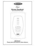
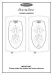
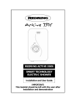
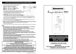
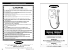
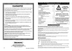
SHOWER HANDBOOK
Full details of terms and conditions are available on request from: -
APPLIED ENERGY PRODUCTS LTD.
MORLEY WAY, PETERBOROUGH. PE2 9JJ.
Tel +44 (0) 844 372 7761 / Fax: +44 (0) 844 372 7762
Website: www.redring.co.uk
12
(A4 Leaflet: 555.2067.01d)
IMPORTANT:
Please retain this booklet for future reference
CONTENTS
How to use your shower
How to maintain your shower
How your shower works
What to do if things go wrong
Installation instructions
Redring after sales service
Additional accessories and spares
Guarantee
……………
……………
……………
……………
…………...
……………
……………
……………
Page
2
3
4
5
6
10
10
12
How to use your shower
1. Ensure the electricity and water are turned on to the unit
2. Function of controls: KNOB “A” – Power selector. (On/off 600 only)
Diagram 1
Diagram 1
KNOB “B”– Adjusts the flow / temperature of the water
BUTTON “C” (620 ONLY) – Starts and ‘Shuts down’ the shower and cools the water
automatically for the next shower.
3. Turning the unit on
Model 600 – Rotate knob “A” clockwise a ¼ turn (one click) this will select full power, the
normal setting, further turns change the power setting (see above).
Model 620 – Press button “C”. (Rotating knob “A” selects the power level, full power being the
normal setting - see above).
4. You will now need to adjust the temperature of the water. Rotate knob “B”.
If the temperature is too low rotate knob “B” anti clockwise and allow 20 seconds for the
temperature to settle. Repeat this procedure until the temperature is to your liking.
5. If the temperature is too high then turn knob “B” clockwise allowing 20 seconds between
adjustments. The final adjustment can be anywhere on the scale.
See diagram 3 for relationship of flow to temperature.
6. Clockwise makes the temperature cooler, anti-clockwise makes the temperature warmer.
7. Once a temperature of your liking has been achieved knob “B” will rarely need adjusting.
e.g. Adjust for variations of incoming mains water temperature between summer and winter.
8. The options of Medium or Low, reduces the power used giving a cooler shower or the option
of reduced flow. These options are mainly for summer usage and knob “B” will have to be
re-adjusted. The cold option (620 only) supplies water with no heat.
9. When you have finished showering.
Model 600 - Rotate knob “A” to the 12 o’clock position (
)
The electricity is switched off and the water will cease to flow immediately.
Model 620 – Press button “C”.
The electricity to the elements is then switched off; water will continue to flow for
approximately 5 seconds before switching off.
This reduces the temperature of the water in the unit.
Diagram 12
Switch the electricity off at the ceiling switch or local isolator.
2
11
Redring After Sales Service
We offer a technical advisory service on the telephone to contractors and other customers with
problems in the field.
RING 0844 372 7766
Some Spare parts (see below) can be supplied against any debit or credit cards.
Remember to quote the exact type of shower, as written on the front of the shower and on this
leaflet.
The model and serial number are located on the bottom face of the shower.
Make a note of these numbers here, and be sure to quote them if you call for advice.
Model Number: 53- . . . . . . . . . . . . . .
Serial Number: . . . . . . . . . . . . . . . . .
Additional Accessories
Catalogue Number
White 2 metre shower hose
WRAS water isolating valve
Shower de-scaling powder
Curtain and rail pack
Curtain and rail pack with Bath mat
Spares
83-593529
93-792452
95-711015
83-792812
83-792811
Catalogue Number
* Please Note:- The fitting of spare parts must be supervised by a suitably qualified person
Front cover complete (Redring 600)
Front cover complete (Redring 620)
Removable Side section
Thermal cutout
Outlet elbow & PRV
Solenoid
Inlet elbow
Gear wheel drive
Miniature microswitch (600 only)
Relay (620 only)
Timer PCB (620 only)
On/off switch (620 only)
Handset (600 only)
Handset (620 only)
Height Adjuster
1.25m long White Shower Hose
93-597808
93-597809
93-591819
93-590306
93-593592
93-591805
93-591804
93-593591
93-597811
93-597812
93-597813
93-590713
93-590736
93-597862
93-593573
93-593538
Spares / accessories can be supplied against any Debit or Credit cards from
Redring Sales Hotline 0844 372 7750
THIS APPLIANCE IS NOT INTENDED FOR USE BY PERSONS (INCLUDING CHILDREN
AND THE INFIRM) WITH REDUCED PHYSICAL, SENSORY OR MENTAL CAPABILITIES,
OR LACK OF EXPERIENCE AND KNOWLEDGE, UNLESS THEY HAVE BEEN GIVEN
SUPERVISION OR INSTRUCTION CONCERNING USE OF THE APPLIANCE BY A
PERSON RESPONSIBLE FOR THEIR SAFETY.
10. Your shower is designed to stabilise temperature changes caused by water pressure
fluctuations.
These can result from toilets being flushed or taps being turned on or off.
When this happens your showering temperature will be held within a controlled band, provided
that the minimum pressure required by the shower is maintained.
11. Your shower requires a minimum operating pressure of 100 kPa (1.0 bar, 14.5 p.s.i.).
At pressures above 100 kPa (1.0 bar, 14.5 p.s.i.) it will minimise temperature fluctuations as
detailed in note 10.
If the water pressure falls below 100 kPa (1.0 bar, 14.5 p.s.i.), it is likely that the pressure
switch will turn off the power to the heating elements, resulting in a cold shower.
12. During normal operation if the shower senses an overheated water temperature then the
thermal cutout will switch off the heating elements.
Water will continue to flow and as the water temperature falls the heating elements will be
turned back on.
If the unit continues to do this then increase the flow rate by turning knob “B” clockwise and
check that the handset does not require de-scaling.
If it still continues, then rotate knob “A” to the MEDIUM power setting, six o’clock position
(Knob B will need adjusting).
13. Note that knob “B” IS NOT A TAP and does not turn the water off.
WARNING! DO NOT SWITCH THE SHOWER ON IF YOU SUSPECT IT OF BEING FROZEN.
WAIT UNTIL YOU ARE SURE IT HAS THAWED OUT.
How to maintain your shower
It is recommended that the shower unit, riser rail, hose etc. can be cleaned using a soft cloth and
that the use of an abrasive or solvent cleaning fluid be avoided.
We recommend that, before cleaning, the isolating switch be turned off, thus avoiding accidentally
switching on the shower.
YOU MUST REGULARLY INSPECT THE SHOWER HOSE FOR WEAR AND DAMAGE.
REPLACE IF NECESSARY, OR EVERY TWO YEARS, WITH AN APPROVED PART.
THIS SHOWER IS DESIGNED AND APPROVED TO EN-60335
WITH THE HANDSET PROVIDED.
UNDER NO CIRCUMSTANCES MUST ANY HANDSET THAT IS NOT APPROVED BY THE
MANUFACTURER BE USED WITH THIS PRODUCT.
IN ORDER TO MAINTAIN THE PERFORMANCE OF YOUR SHOWER
YOU MUST CLEAN THE SHOWERHEAD REGULARLY.
All water contains particles of lime-scale, which build up in the showerhead and unit reducing the
performance.
It is therefore important to clean the showerhead by simply rubbing the rubber nozzles regularly.
In some winter conditions, when the incoming mains water is particularly cold it may be necessary
to select the inner or outer spray pattern only. This will ensure correct operation of the shower
with a slightly lower water flow rate.
NOTE: After use it is normal for some water to drip from the showerhead for a few moments.
This inhibits lime-scale build-up over prolonged use.
CHILDREN SHOULD BE SUPERVISED TO ENSURE THAT THEY DO NOT PLAY WITH
THE APPLIANCE.
10
3
How your shower works
Your shower is designed for convenience, economy and safety of use
600 Model
1. Water is heated instantaneously as it flows over the elements in the copper heating tube.
620 Model
Diagram 10
Diagram 2
7. Operate the shower first without the handset to flush
out any particles, fit handset and then operate the
shower as explained previously and check:
2. The required water temperature is achieved by adjusting the rate of water flow.
Diagram 3 shows the principle involved in relating temperature rise to flow rate.
The higher the water flow the lower the temperature rise, and vice versa.
The temperature of the water supplied from the mains can vary
considerably throughout the year from 5 to 20°C.
This means that in Winter, the flow rate will be less than in the Summer
to achieve the same outlet temperature.
In summer the “MED (medium)” or “LOW” power setting may give
adequate hot water.
Diagram 11
a) That the water gets to a satisfactory temperature.
Diagram 3
3. The heaters are only switched on when sufficient water is flowing.
This is done automatically with a switch, which works on water pressure.
4. The water is turned on and off by the solenoid valve built into the shower.
This is switched on by rotating Knob “A” or pressing button “C” on model 620 only.
b) Power selection does give a change in water
temperature.
c) Check again for leaks.
d) That the holes in the spray plate are not blocked.
e) Water flow can be adjusted by knob B.
8. DEMONSTRATE OPERATION TO USER
9. LEAVE THESE INSTRUCTIONS WITH THE USER
FOR FUTURE REFERENCE.
5. The flow of water is automatically held at the level set by the user even though the supply
pressure may vary. (See “How to use your shower” note 10).
6. If the water supply falls below a set limit, the pressure switch will switch off the power to the
heating elements in the copper heating tube.
7. As a further safeguard, a thermal cutout switches the power off if the water temperature climbs
above a set limit. The cutout gives an audible click when it switches off, but will reset itself if
water is run through the shower for 10 to 20 seconds.
8. The pressure relief device is to safeguard against abnormal pressure conditions, and provides
a level of appliance protection should an excessive build up of pressure occur within the unit.
4
9
5. It is permissible to use a WRAS (Water Regulations Advisory Scheme) approved sealant
sparingly whilst avoiding excess finding its way into shower operating parts.
6. With the isolating valve connected, flush the pipe-work through to remove any particles etc
before making the final connection to the shower. Blockage in the waterways (particularly the
handset and solenoid valve) will prevent the heater working properly.
7. The shower is designed to have an open outlet and should only be used with manufacturer
recommended fittings. Do not connect the handset until after the shower removable side
section and front cover are fitted.
What to do if things go wrong
SELF HELP
If the shower is not working satisfactorily, make the following checks before calling out the
installer. Any of these adjustments could restore the performance
a) Water too HOT
Clean spray plate holes.
Select outer or combination spray patterns (620 only).
WARNING! DO NOT FIT A TAP ON THE SHOWER OUTLET.
TAKE CARE TO AVOID RESTRICTING THE OUTLET AND FLOW
FROM THE HANDSET OR THE PRESSURE RELIEF DEVICE.
Switch power to MEDIUM setting.
b) Water too COLD
c) Electrical Connections
The electrical installation must be in accordance with the current BS.7671 (I.E.E. regulations)
and “Part P” of the Building Regulations and/or local regulations.
1. The shower is designed for a single-phase A.C. electrical supply.
Please check the rating plate on the unit to see what details apply.
AS A GUIDE ONLY (* Only applies if external earth impedance is less than 0.35 Ohms)
Rating
7.5 / 6.9kW 240 / 230V
.
8.5 / 7.8kW 240 / 230V
9.5 / 8.7kW 240 / 230V
Cable Sizes
4.0mm²
6.0mm²
6.0mm²
10.0mm²
6.0mm²
10.0mm²
6.0mm²
10.0mm²
6.0mm²
10.0mm²
6.0mm²
10.0mm²
Fuse / MCB
32A Type B MCB
40A Type B MCB
40A Type B MCB
45A BS.1361 fuse
40A Type B MCB
45A BS.1361 fuse
Cable Length
21m Max.
35m Max.
27m Max.
45m Max.
27m Max.
45m Max.
12m Max.*
21m Max.*
27m Max.
45m Max.
12m Max.*
21m Max.*
Remember to uprate the cable if it runs in thermal insulation in a loft, or for a longer distance.
c) Spray pattern
poor
d) Water goes cold
while using
shower
e) Broken parts
Raise position of handset.
Please contact our spares department on 0844 372 7750.
Fitting instructions are provided with spares.
If the previous checks fail to restore the performance, you should seek professional help.
The person who installed the shower is probably the best one to repair it and is certainly
the person to contact if you have a problem in the guarantee period.
The following additional checklist is provided for the benefit of the qualified service person.
WARNING! SWITCH OFF THE ELECTRICITY AT THE ISOLATING SWITCH
BEFORE REMOVING THE COVER TO MAKE CHECKS.
a) Water too HOT
Water flow restricted by blockage in filter of solenoid valve.
Switch off water and undo plastic nut on elbow, loosen brass nut to swing
elbow away from solenoid.
Remove filter in solenoid with long nosed pliers and flush clean.
Check circuit through thermal cut-out
Check circuit through microswitch on the pressure switch
Check each element circuit.
5. Fit the front cover into position making sure the knob is aligned
correctly with the flow valve (see diagram 11).
8
Switch power to FULL setting.
Clean spray plate and flush heater.
Select inner / outer spray pattern (620 only).
Check water pressure has not fallen so far as to let pressure switch cut out,
e.g. another tap drawing water off.
PROFESSIONAL SERVICE
b) Water too COLD
4. Cut back cable as in diagram 9.
Connect cable to terminal block making sure that ALL the retaining
screws are VERY tight and that no cable insulation is trapped in the
block.
WARNING!
FAILURE TO COMPLY WITH THESE INSTRUCTIONS COULD
RESULT IN A FAILURE OF THE TERMINAL BLOCK AND CABLING.
6. Fit the front cover into position making sure the knob is aligned
correctly with the flow valve (see diagram 11).
WARNING! TAKE CARE WHEN REPLACING THE FRONT COVER
TO AVOID DAMAGING ANY COMPONENTS.
Increase pressure of water supply e.g. fully open service valve or stop cock.
Check hose is not kinked restricting the water flow.
Decrease water flow by adjusting the temperature control anti-clockwise.
Select inner or outer spray patterns only (620 only).
2. A means for disconnection in all poles must be incorporated in the fixed wiring in accordance
with the wiring rules. We recommend ceiling switches.
3. WARNING! This appliance must be earthed.
Increase water flow by adjusting the temperature control clockwise.
Diagram 9
c) Water leaks from
burst pressure
relief valve
d) Water does not
flow when Knob
“A” is rotated
(when button
“C” is pressed 620 only)
Check tightness of electrical connections.
Check for cause of high pressure and remove it.
i.e. Blockage on outlet or blocked spray plate.
Replace the pressure relief disc (not covered by guarantee).
Check the circuit through the solenoid coil.
Check circuit through mini microswitch (push switch – 620 only)
Possible timer PCB fault (620 only). If defective, then replace.
Power supply not reaching shower.
5
Installation instructions
WARNING! ALL WIRING AND INSTALLATION MUST BE SUPERVISED
BY A SUITABLY QUALIFIED PERSON
WARNING! DO NOT INSTALL THIS SHOWER IN A ROOM
WHERE IT MAY BE SUBJECT TO FREEZING
8. Do not obstruct the pressure relief device found in the back-plate slot underneath the outlet
connection (see diagram 3), especially if silicone sealant or similar materials are used around
the edges of the back-plate.
9. There are a number of shields in the shower unit. These are important for the correct
operation of this shower and MUST NOT be removed under any circumstances.
Diagram 7
We recommend that the installation be done in the following sequence.
a) Fixing the shower to the wall
b) Plumbing
c) Electrical connections
Diagram 4
a) Fixing the shower to the wall
1. Position the riser rail at the height recommended in diagram 4 and
mark its position.
Diagram 6
2. Position the heater so the sides of the unit are vertical and the top is
level with, or up to 0.6 metres (2ft) maximum below the top of the
riser rail. Choose a flat piece of wall to avoid the possibility of
distorting the back plate thus making the front cover a poor fit
b) Plumbing (see diagram 8)
3. Adjust the positions to get the most convenient arrangement taking
the following into account.
a) The possible need to use the handset over the sink for hair washing etc.
b) The heater must not be mounted in the direct spray from the showerhead.
c) The handset must not be able to come into contact with any used water in the bath or
basin. If it can, even after the hose has been retained by the hose retainer (see diagram
12) then a vacuum breaker must be fitted.
The heater should be connected to the mains cold water supply.
This must have a minimum running pressure of 100kPa, 1.0 bar (14.5 p.s.i)
and a maximum pressure of 1000kPa, 10 bar (145 p.s.i).
Before connecting the pipe-work to the shower ensure that pipe-work is flushed out.
4. Fix the riser rail with screws provided. The fixing holes at the base of the brackets will be
disclosed by removing the plastic fronts. Assemble as shown in diagram 12.
5. Decide the position of the electrical cable inside the unit.
If top or bottom entry is chosen (according to diagram 5),
cut away the walls of the back-plate as shown in diagram 7.
There is also the option to fit the cable from the rear in the
channel provided.
Diagram 5
6. Decide the cut away position of entry of the cold water pipe
into the unit.
Cut away the back-plate and front cover as shown in
diagram 6 or 7.
There is also the option to have rear entry (see later section
on plumbing).
7. If you have not yet done so, remove the front cover (complete
with control knob) of the unit by undoing the retaining screws
at the top and bottom of the unit and lifting the cover off.
The top-fixing hole is a keyhole slot, and should be marked
and drilled first.
Tighten top screw with head protruding about 10mm from wall
and hook the back-plate over the screw head.
This allows for correct and accurate alignment of your shower
before marking and fixing the bottom/side position.
You may not wish to tighten up all 3 other screws at this stage as the holes are elongated to
allow for adjustment after other connections have taken place.
6
Diagram 8
1. It is recommended that a WRAS (Water Regulations Advisory Scheme) listed isolating valve is
fitted to the incoming mains cold water before the shower unit. This will allow the unit to be
serviced or exchanged without having to turn off the water at the mains stop valve.
2. The heater can be fed from a header tank provided this has a minimum head height of
10.5 metres (35ft).
3. Ø15mm copper or stainless steel pipe should be used with a standard compression fitting.
In multiple shower installations correct pipe-work sizes should be calculated to maintain
adequate flow to each shower.
4. a) If top entry is chosen, turn the elbow 180° into the required position and fit a standard
15mm in-line compression fitting.
There is a removable side section, which will aid you with this (diagram 6).
b)
If rear entry is chosen, turn the elbow 180° and treat it as top entry except for the fitting of
a ‘Yorkshire’ elbow in the rear channel. The removable side section will again be an aid.
7