1
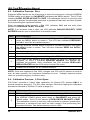
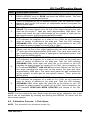
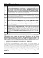
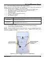
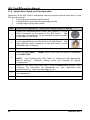
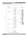
Indoor Environment Quality Monitor Instruction 1509-9001 Operation Manual Rev. 1 - July 2011 Product Leadership • Training • Service • Reliability IEQ Chek Operation Manual ii 1509-9001 Rev 1 IEQ Chek Operation Manual IMPORTANT NOTE READ AND UNDERSTAND THIS MANUAL PRIOR TO USING THIS INSTRUMENT. CAREFULLY READ THE WARRANTY POLICY, SERVICE POLICY, NOTICES, DISCLAIMERS AND REVISIONS ON THE FOLLOWING PAGES. THIS INSTRUMENT SHOULD BE INSPECTED AND CALIBRATED REGULARLY BY A QUALIFIED AND TRAINED TECHNICIAN. THIS INSTRUMENT HAS NOT BEEN DESIGNED TO BE INTRINSICALLY SAFE IN HAZARDOUS OR EXPLOSION-RATED ENVIRONMENTS. FOR YOUR SAFETY, DO NOT USE IT IN AREAS CLASSIFIED AS HAZARDOUS AREAS (E.G., EXPLOSION-RATED ENVIRONMENTS). INSTRUMENT SERIAL NUMBER: PURCHASE DATE: PURCHASED FROM: WARRANTY POLICY BACHARACH, INC. WARRANTS THIS INSTRUMENT, EXCLUDING SENSORS, TO BE FREE FROM DEFECTS IN MATERIALS AND WORKMANSHIP FOR A PERIOD OF TWO YEARS FROM THE DATE OF PURCHASE BY THE ORIGINAL OWNER. THE SENSORS HAVE A WARRANTY PERIOD OF ONE YEAR FROM THE DATE OF PURCHASE. IF THE PRODUCT SHOULD BECOME DEFECTIVE WITHIN THIS WARRANTY PERIOD, WE WILL REPAIR OR REPLACE IT AT OUR DISCRETION. THE WARRANTY STATUS MAY BE AFFECTED IF THE INSTRUMENT HAS NOT BEEN USED AND MAINTAINED PER THE INSTRUCTIONS IN THIS MANUAL OR HAS BEEN ABUSED, DAMAGED, OR MODIFIED IN ANY WAY. THIS INSTRUMENT IS ONLY TO BE USED FOR PURPOSES STATED HEREIN. THE MANUFACTURER IS NOT LIABLE FOR AUXILIARY INTERFACED EQUIPMENT OR CONSEQUENTIAL DAMAGE. DUE TO ONGOING RESEARCH, DEVELOPMENT, AND PRODUCT TESTING, THE MANUFACTURER RESERVES THE RIGHT TO CHANGE SPECIFICATIONS WITHOUT NOTICE. THE INFORMATION CONTAINED HEREIN IS BASED ON DATA CONSIDERED ACCURATE. HOWEVER, NO WARRANTY IS EXPRESSED OR IMPLIED REGARDING THE ACCURACY OF THIS DATA. ALL GOODS MUST BE SHIPPED TO THE MANUFACTURER BY PREPAID FREIGHT. ALL RETURNED GOODS MUST BE PRE-AUTHORIZED BY OBTAINING A RETURN MERCHANDISE AUTHORIZATION (RMA) NUMBER. CONTACT THE MANUFACTURER FOR A NUMBER AND PROCEDURES REQUIRED FOR PRODUCT TRANSPORT. 1509-9001 Rev 1 iii IEQ Chek Operation Manual SERVICE POLICY BACHARACH, INC. MAINTAINS AN INSTRUMENT SERVICE FACILITY AT THE FACTORY. SOME BACHARACH DISTRIBUTORS / AGENTS MAY ALSO HAVE REPAIR FACILITIES, HOWEVER, BACHARACH ASSUMES NO LIABILITY FOR SERVICE PERFORMED BY ANYONE OTHER THAN BACHARACH PERSONNEL. REPAIRS ARE WARRANTED FOR 90 DAYS AFTER DATE OF SHIPMENT (SENSORS, PUMPS, FILTERS AND BATTERIES HAVE INDIVIDUAL WARRANTIES). SHOULD YOUR INSTRUMENT REQUIRE NON-WARRANTY REPAIR, YOU MAY CONTACT THE DISTRIBUTOR FROM WHOM IT WAS PURCHASED OR YOU MAY CONTACT BACHARACH DIRECTLY. IF BACHARACH IS TO DO THE REPAIR WORK, SEND THE INSTRUMENT, PREPAID, TO BACHARACH, INC. AT THE FOLLOWING ADDRESS. BACHARACH, INC. 621 HUNT VALLEY CIRCLE NEW KENSINGTON, PA 15068 ATTENTION: SERVICE DEPARTMENT ALWAYS INCLUDE YOUR RMA #, ADDRESS, TELEPHONE NUMBER, CONTACT NAME, SHIPPING/BILLING INFORMATION AND A DESCRIPTION OF THE DEFECT AS YOU PERCEIVE IT. YOU WILL BE CONTACTED WITH A COST ESTIMATE FOR EXPECTED REPAIRS PRIOR TO THE PERFORMANCE OF ANY SERVICE WORK. FOR LIABILITY REASONS, BACHARACH HAS A POLICY OF PERFORMING ALL NEEDED REPAIRS TO RESTORE THE INSTRUMENT TO FULL OPERATING CONDITION. PRIOR TO SHIPPING EQUIPMENT TO BACHARACH, CONTACT OUR OFFICE FOR AN RMA # (RETURNED MERCHANDISE AUTHORIZATION). ALL RETURNED GOODS MUST BE ACCOMPANIED WITH AN RMA NUMBER. PACK THE EQUIPMENT WELL (IN ITS ORIGINAL PACKING IF POSSIBLE), AS BACHARACH CANNOT BE HELD RESPONSIBLE FOR ANY DAMAGE INCURRED DURING SHIPPING TO OUR FACILITY. NOTICES COPYRIGHTS: THIS MANUAL IS SUBJECT TO COPYRIGHT PROTECTION; ALL RIGHTS ARE RESERVED UNDER INTERNATIONAL AND DOMESTIC COPYRIGHT LAWS. THIS MANUAL MAY NOT BE COPIED OR TRANSLATED, IN WHOLE OR IN PART, IN ANY MANNER OR FORMAT, WITHOUT THE WRITTEN PERMISSION OF BACHARACH, INC. ALL SOFTWARE WHICH BACHARACH UTILIZES AND/OR DISTRIBUTES, HOLDS A PROPRIETARY INTEREST AND IS ALSO SUBJECT TO COPYRIGHT PROTECTION AND ALL RIGHTS ARE RESERVED. NO PARTY MAY USE OR COPY SUCH SOFTWARE IN ANY MANNER OR FORMAT, EXCEPT TO THE EXTENT THAT BACHARACH GRANTS THEM A LICENSE TO DO SO. IF THIS SOFTWARE IS BEING LOADED ONTO MORE THAN ONE COMPUTER, EXTRA SOFTWARE LICENSES MUST BE PURCHASED. iv 1509-9001 Rev 1 IEQ Chek Operation Manual DISCLAIMER UNDER NO CIRCUMSTANCES WILL BACHARACH, INC. BE LIABLE FOR ANY CLAIMS, LOSSES, OR DAMAGES RESULTING FROM OR ARISING OUT OF THE REPAIR OR MODIFICATION OF THIS EQUIPMENT BY A PARTY OTHER THAN BACHARACH SERVICE TECHNICIANS, OR BY OPERATION OR USE OF THE EQUIPMENT OTHER THAN IN ACCORDANCE WITH THE PRINTED INSTRUCTIONS CONTAINED WITHIN THIS MANUAL OR IF THE EQUIPMENT HAS BEEN IMPROPERLY MAINTAINED OR SUBJECTED TO NEGLECT OR ACCIDENT. ANY OF THE FORGOING WILL VOID THE WARRANTY. REVISIONS BACHARACH, INC. MAKES NO WARRANTY OR REPRESENTATION, EXPRESSED OR IMPLIED INCLUDING ANY WARRANTY OF MERCHANTABILITY OR FITNESS FOR PURPOSE, WITH RESPECT TO THIS MANUAL. ALL INFORMATION CONTAINED IN THIS MANUAL IS BELIEVED TO BE TRUE AND ACCURATE AT THE TIME OF PRINTING. HOWEVER, BACHARACH RESERVES THE RIGHT TO MAKE CHANGES AT ANY TIME WITHOUT NOTICE. REVISED COPIES OF THIS MANUAL CAN BE OBTAINED BY CONTACTING BACHARACH, INC. SHOULD YOU DETECT ANY ERRORS OR OMISSIONS IN THIS MANUAL, PLEASE CONTACT THE COMPANY AT THE FOLLOWING ADDRESS. BACHARACH, INC. 621 HUNT VALLEY CIRCLE NEW KENSINGTON, PA 15068-7074 USA TOLL FREE: FAX: E-MAIL: WEBSITE: 1-800-736-4666 724-334-5001 [email protected] www.MyBacharach.com IN NO EVENT WILL BACHARACH, INC., OR ITS OFFICERS OR EMPLOYEES BE LIABLE FOR ANY DIRECT, SPECIAL, INCIDENTAL, OR CONSEQUENTIAL DAMAGES RESULTING FROM ANY DEFECT IN ANY MANUAL, EVEN IF ADVISED OF THE POSSIBILITY OF SUCH DAMAGES. 1509-9001 Rev 1 v IEQ Chek Operation Manual TABLE OF CONTENTS 1. OVERVIEW ................................................................................................................ 1 1.1. General Description ............................................................................................ 1 1.2. IEQ Chek™ Shipping Checklist .......................................................................... 2 1.3. Key Features ...................................................................................................... 2 1.4. Sensor Configuration Notes ................................................................................ 2 2 SPECIFICATIONS ..................................................................................................... 3 2.1. General............................................................................................................... 3 2.2. IQ Chek™ DataLogging Software (Optional)....................................................... 5 2.3. Available “Plug-and-Play” Sensors...................................................................... 5 3. KEY COMPONENTS.................................................................................................. 6 3.1. Key Components: Front and Bottom Views ......................................................... 6 3.2. Key Components: Left Side View ........................................................................ 7 3.3. Key Components: Top and Back Views .............................................................. 8 4. INSTRUMENT OPERATION ...................................................................................... 9 4.1. General............................................................................................................... 9 4.2. Switching the Instrument On/Off ........................................................................10 4.3. Battery and Battery Warnings ............................................................................10 4.4. Main Menu Functional Overview ........................................................................11 5. MENU FUNCTION DETAILS ................................................................................... 12 5.1. Calibrate Menu ..................................................................................................12 5.2. Settings Menu....................................................................................................13 5.3. Datalog Menu ....................................................................................................15 5.4. Alarm Menu .......................................................................................................17 5.5. Info Menu ..........................................................................................................18 5.6. USB Menu .........................................................................................................19 6. CALIBRATION ......................................................................................................... 19 6.1. Overview ...........................................................................................................19 6.2. Requirements and Cautions...............................................................................19 6.3. Calibration Process: Zero .................................................................................20 6.4. Calibration Process: 3-Point Span ....................................................................20 6.5. Calibration Process: 1-Point Span ....................................................................21 7. ADDING OR CHANGING PLUG-AND-PLAY SENSORS......................................... 22 8. MAINTENANCE ....................................................................................................... 25 9. IEQ CHEK TROUBLESHOOTING ........................................................................ 25 10. ACCESSORIES ....................................................................................................... 26 10.1. Hard Shell, Foam-Lined Carrying/Transport Case ............................................26 10.2. Extended Operation (Short Term) External Battery ..........................................26 10.3. Extended Operation (Long Term) External Battery...........................................26 10.4. Standard Gas Sample Probe ...........................................................................26 10.5. IQ Chek DataLogging Kit...............................................................................26 vi 1509-9001 Rev 1 IEQ Chek Operation Manual 11. DUAL PROBE VERSION ......................................................................................... 27 11.1. Applications Overview......................................................................................27 11.2. Probes .............................................................................................................28 11.3. Instrument Kits for Dual-Probe Applications .....................................................29 11.4. Application Setup and Configuration ................................................................30 12. MENU ARCHITECTURE .......................................................................................... 31 1509-9001 Rev 1 vii IEQ Chek Operation Manual viii 1509-9001 Rev 1 IEQ Chek Operation Manual 1. OVERVIEW 1.1. General Description Thank you for purchasing the IEQ Chek™ indoor environmental quality monitor. The IEQ Chek™ is an easy-to-use, portable, information-recording device for monitoring trends that pertain to indoor air quality. The IEQ Chek™ is a battery-powered, portable, indoor air quality monitor and information recording (data logging) instrument designed for both intermittent and continuous operation. Its intended use is for indoor environments. A basic instrument includes a multi-line LCD alpha numeric display, audible alarm, rechargeable batteries, temperature and relative humidity sensors, and operation manual. The IEQ Chek™ is equipped with top-mounted temperature and relative humidity sensors to aid in verifying readings providing a comprehensive indication of air quality. Information readings can be written to a plug-in (and removable) flash card to protect your recorded information. The sample rate can be adjusted using the supplied software or through the instrument menu. The instrument may be hand held, stood upright on a flat surface, or fastened to a wall for permanent or semi-permanent use. The IEQ Chek™ series of instruments are manufactured with plug-and-play, interchangeable sensor modules to allow for the testing of multiple gases. The specifications listed in this manual indicate a wide array of supported sensors. These sensors may be changed in the field and operated within minutes (accurate readings will require more time as each sensor type has different warm-up/stabilization periods before they are able to perform to published specifications). NOTE: Calibration and repair are available at our manufacturing facility and through some of our authorized and trained distributors. The IEQ Chek™ can reliably record timebased information, which can be downloaded via the USB port located on the right side of the instrument. Any computer running Microsoft Windows XP or higher (with an available USB communications port) can accommodate the optional IQ Chek™ software. If after reading the manual you have any questions, please contact our service department for technical support. Figure 1-1. IEQ Chek™ The user can add up to five additional plug-and-play sensors (electrochemical toxic gas and/or oxygen, infrared CO2, PID or catalytic combustible/flammable gas) internally for a maximum of seven internal sensors. Currently, a large selection of sensors is available to choose from. Refer to page 5. 1509-9001 Rev 0 1 IEQ Chek Operation Manual 1.2. IEQ Chek™ Shipping Checklist This checklist ensures that you have received everything required to run your IEQ Chek. If you do not receive any of the items listed below, contact the factory immediately. • IEQ Chek™ instrument • AC wall adapter (6V @ 850 mA) • Nickel-metal Hydride rechargeable batteries (3 × “AA”) • Calibration adapter (pump versions only) • Operation manual • IQ Chek™ datalogging kit (optional) • Other specified accessories (see original sales order) 1.3. Key Features Features of the IEQ Chek™ include the following. • Light weight, contoured, and comfortable-to-hold enclosure • Flame rated ABS/Polycarbonate enclosure • Displays all installed sensors simultaneously on backlit LCD display • Multi-function, easy-to-use menu • Operates from nickel metal hydride (NiMH) rechargeable batteries (standard), alkaline batteries, or continuously from the plug-in power adapter • Hangs on a wall (rear slot), mounts on a camera tripod, or sits flat on a desk • Accommodates a standard cable lock for securing the instrument in place • Samples air with internal sample draw pump (pump version only) • Accommodates electrochemical, catalytic, PID, or infrared sensor types • 16 different plug-and-play sensor choices • Logs information and events to flash card (with optional datalogging kit) • USB data downloading and auxiliary uploading from remote probes • Optional IQ Check software compatible with Windows XP, Vista, and 7. 1.4. Sensor Configuration Notes It is important to note that although the IEQ Chek™ will accommodate seven sensors (and five of those sensor locations are plug and play for gas sensors), there are sensor placement considerations. Either of the two front sensor locations will accommodate an infrared CO2 sensor, PID sensor, or catalytic combustible (flammable) gas sensor. Of the five plug-and-play sensor locations, three are for electrochemical sensors. If the user selects an oxygen (O2) sensor, it must be fitted to a specific sensor location (rear center position, determined by looking at the front of the instrument). If the user selects a nitric oxide (NO), requiring electronic bias within the circuit, it must be fitted to one specific sensor location (left rear position, determined by looking at the front of the instrument). Two sensors requiring bias cannot be fitted in the same instrument at the same time. Reference the photos on pages 23 and 24 for specific sensor locations. 2 1509-9001 Rev 1 IEQ Chek Operation Manual 2 SPECIFICATIONS 2.1. General Categories/Subcategories Enclosure Power User Interface Monitoring Mode Environmental CE Certification Standards 1509-9001 Rev 1 Descriptions Dimensions LxWxD 7.75” x 3.87” x 3.06” (19.7 cm x 9.8 cm x 7.8 cm) Weight 20 ounces (567 grams) including batteries Covers Sensor cover (removable; top of enclosure) Battery cover (removable; bottom of enclosure) Mounting Options Threaded insert (bottom of enclosure) to accommodate a camera tripod Teardrop slot at the upper rear to allow instrument to hang on a wall Flat base for sitting on a flat table or desktop Security Slot for cable lock (lower right side) Construction Custom molded, rugged, contoured, ABS/Polycarbonate Flammability UL94 rating Standard Three rechargeable NiMH batteries Option Three user-supplied AA alkaline batteries Protection In-circuit protection diode (if the batteries are accidently inserted with reversed polarity) Continuous Plug-in, 6V DC, class-III, 2A DC max. wall adapter Display Back-lit, multi-line LCD alphanumeric display Buttons 3 tactile push-buttons for user access Audio Openings at front top left for audible sounder Internal Automatic sample pump for “active” sampling of target environment Option Diffusion monitoring version Temperature Operating: Storage: 5° to 50° C -20° to 60° C Relative Humidity Operating: Storage: 0 to 99% RH non-condensing 0 to 99% RH non-condensing Safety I.S. EN 61010-1:2001 (Ed.2) Emissions EN 50270:2006 Immunity EN 50270:2006 (41° to 122° F) (-4° to 140° F) 3 IEQ Chek Operation Manual 3.06 7.75 3.87″ (9.8 cm) Figure 2-1. IEQ Chek™ Dimensions 4 1509-9001 Rev 1 IEQ Chek Operation Manual 2.2. IQ Chek™ DataLogging Software (Optional) Minimum system requirements to operate the optional IQ Chek DataLogging Software are listed in the table below. Categories Descriptions Microprocessor Personal computer with Pentium III class processor or better RAM 512MB RAM (minimum) Operating System Windows XP, Vista, or 7 Disk Space At least 1 MB of available disk space. Additional space is required to store logger files and graph files. Interface An available USB port 2.3. Available “Plug-and-Play” Sensors Sensor Standard Measurement Range Sensor Standard Measurement Range 0 - 5000 ppm Combustible Gases/Vapors 0 - 100% LEL 0 - 10,000 ppm Oxygen (O2) 0 - 25.0% volume 0 - 5% volume Ammonia (NH3) 0 - 50 ppm 0 - 20% volume Hydrogen Sulfide (H2S) 0 - 50 ppm 0 - 100% volume Sulfur Dioxide (SO2) 0 - 20 ppm Carbon Monoxide (CO) 0 - 50 ppm Formaldehyde (HCHO) 0 - 10 ppm Nitrogen Dioxide (NO2) 0 - 5.0 ppm Nitric Oxide (NO) 0 - 100 ppm Carbon Dioxide (CO2) Total Volatile Organic Compounds (TVOC) 0 - 50 ppm 0 - 300 ppm NOTE: Not all of the above sensors are available from stock. Delivery time for sensors ordered will vary depending on which sensors are ordered, how many are ordered and measurement range desired. NOTE: Other measurement ranges are available for some sensors. Contact Bacharach with desired range to confirm availability. NOTE: Some of the these sensors must be calibrated with correlation gases because they are more readily available. If the customer wishes them to be calibrated with the exact target gas, extra charges will apply to acquire the specific gas if and when available. In these cases, customer will be required to take delivery of the special cylinder of span gas and dangerous goods and shipping costs will apply. NOTE: Some of the above sensors have cross sensitivities to other gases (interfering gases). Please refer to the sensor specification chart before ordering a specific sensor if your application may have some of the interfering gases present. 1509-9001 Rev 1 5 IEQ Chek Operation Manual 3. KEY COMPONENTS 3.1. Key Components: Front and Bottom Views TEMPERATURE & RH SENSORS ARE INSTALLED IN A PLASTIC SINTER THAT ATTACHES TO THE TOP OF THE SENSOR COVER SENSOR COVER SPEAKER LEXAN LABEL MULTI-LINE, MANUAL BACK-LIT, LCD, ALPHA-NUMERIC, DIGITAL DISPLAY WALL ADAPTER PLUG (ON SIDE) 3-BUTTON MEMBRANE KEYPAD NOTE: 6VDC ONLY BOTTOM VIEW BRASS THREAD FOR TRIPOD MOUNTING BATTERY DOOR Figure 3-1. IEQ Chek™ Key Components (Front and Bottom Views) 6 1509-9001 Rev 1 IEQ Chek Operation Manual 3.2. Key Components: Left Side View AIR VENTS FOR VENTING BUILT-UP HEAT FROM INTERNAL SENSORS PUMP INLET FITTING NOTE: ATTACHING FLOW ADAPTER REQUIRES ONLY A COUPLE TURNS OF THE FITTING. RUBBER COVER FOR USB SLOT, AUXILIARY SLOT, AND SD FLASH CARD SLOT RUBBER COVER REMOVED AUXILIARY PORT FOR REMOTE PROBES SLOT FOR SECURING CABLE LOCK (SIMILAR TO THOSE USED FOR LAPTOP COMPUTERS) SLOT FOR SD FLASH CARD USB PORT FOR DOWNLOADING TO PC Figure 3-2. IEQ Chek™ Key Components (Side View) 1509-9001 Rev 1 7 IEQ Chek Operation Manual 3.3. Key Components: Top and Back Views SECURING SCREW FOR SENSOR COVER. DO NOT OVER TIGHTEN. DIFFUSION VERSION TEMPERATURE AND RH SENSORS (INSIDE SINTER) PUMP VERSION OUTLET HOLE FOR NOTE: The SAMPLED AIR. DO NOT diffusion version is PLUG/BLOCK THIS HOLE. NOT supplied with an internal pump. Sensors “breath” through openings in the sensor chamber cap. Response time is very good for most gases. ACCESS HOLES TO THREE SCREWS HOLDING FRONT AND REAR ENCLOSURE HALVES TOGETHER SECURING SCREW FOR SENSOR COVER. DO NOT OVER TIGHTEN. TEMPERATURE AND RH SENSORS (INSIDE SINTER) MOLDED SLOT FOR HANGING INSTRUMENT ON WALL SERIAL NUMBER LABEL Figure 3-3. IEQ Chek™ Key Components (Top and Back Views) 8 1509-9001 Rev 1 IEQ Chek Operation Manual 4. INSTRUMENT OPERATION 4.1. General The IEQ Chek™ has an extensive menu system allowing the user to access a wide range of features and functionality. All features and functions can be set to meet the user’s specific requirements. BUTTON PRESSING: The three membrane push-buttons on the front face of the instrument should be pressed firmly. They have been designed such that an accidental light touch does not register and change something unintentionally. SECURITY CODE: Some functions within the menu system are protected by a security code to prevent unauthorized or untrained personnel from accessing them and changing critical values. All IEQ Chek™ instruments are shipped from the factory with a generic security code of: 1 2 3 4 It is recommended that the user change this to a code known only to authorized personnel. DISPLAY ICONS: In addition to menus and sensor readings, the LCD of the IEQ Chek™ may display icons to inform or alert the operator of certain operating conditions. A summary of the common icons is provided below. Icon Name Description Battery This icon is displayed when the instrument is being powered by batteries. The battery icon flashes when the battery power is low. DataLogging This icon is displayed when datalogging is enabled. AC Adapter This icon is displayed when the AC adapter is connected and the unit is charging. Lock This icon is displayed when the instrument is locked. To unlock the instrument, enter the 4-digit security code. Temperature This icon is displayed next to the current temperature reading. 1509-9001 Rev 1 9 IEQ Chek Operation Manual 4.2. Switching the Instrument On/Off NOTE: When using push-buttons on front of instrument enclosure, press firmly and watch the display for movement. A light finger press may not engage the domed contact. This is to prevent accidental changes to settings. SWITCH ON: Press the “MENU” button down momentarily then release. The multi-line LCD will scroll through each of the information functions as it warms up. SWITCH OFF: Hold the “MENU” button down for five to six seconds then release. The multi-line LCD will indicate Shutting monitor off. After power up, the display indicates IEQ Chek™, PORTABLE AIR QUALITY MONITOR, then WARMING UP UNIT PLEASE WAIT… and the inner sample draw pump (if applicable) starts automatically sampling the environment. A symbol at the bottom left corner of the display will indicate if the instrument is operating from batteries or the plug-in wall adapter. After the warm-up period (approximately 3 minutes), the LCD indicates all installed sensors, their current real-time readings, and a flashing cursor. NOTE: More accurate real-time readings will occur after the sensors have warmed up and stabilized. NOTE: Warm-up mode can be skipped by holding the MENU button for 3-5 seconds. 4.3. Battery and Battery Warnings The IEQ Chek™ operates from three different power sources: Rechargeable nickel metal hydride NiMH) batteries (3 × AA), disposable alkaline batteries (3 × AA), or plug-in wall adapter/battery charger. The IEQ Chek™ is supplied with and configured for rechargeable batteries from the factory. CAUTION: To change from one type of battery to another (e.g., rechargeable to alkaline), you must first make the change through the instrument menu. NOTE: The battery tabs are such that even if batteries are installed incorrectly (with polarities reversed), no damage will occur. Nevertheless, always take care when installing any kind of battery. NOTE: The instrument will not charge the NiMH batteries unless the instrument is switched off. CAUTION: A yellow warning label is on the battery door of the IEQ Chek™ to alert users of the potential risk of damage to the device if alkaline batteries are installed and the user mistakenly attempts to recharge them with the supplied wall adapter. Recharging alkaline batteries could cause them to leak, thus creating potential harm and/or physical damage to the instrument. Damage caused by this type of action is not covered under warranty and the manufacturer is not responsible. 10 1509-9001 Rev 1 IEQ Chek Operation Manual 4.4. Main Menu Functional Overview Pressing the MENU button after the main sensor array is displayed allows the user to enter the extensive menu system. The first menu display includes the following. PREVIOUS CALIBRATE SETTINGS DATALOG ALARM INFO USB NOTE: In all cases, use the ARROW DOWN or ARROW UP buttons to scroll through any displayed menu and use the MENU button to select any highlighted choices. PREVIOUS: Allows the user to go back to the previous function. Pressing the MENU button repeatedly at “PREVIOUS” will step the user back one menu at a time until he finally reaches the main sensor realtime display. Alternatively, hold down the MENU button for approximately 6 to 7 seconds and the LCD will jump back to the main, real-time sensor display. CALIBRATE: Allows the user to enter the calibration section of the menu. This section is protected by a security code to prevent unauthorized people from attempting to calibrate the sensors. Refer to the calibration section starting on page 19. SETTINGS: This menu item provides the user with a number of instrument functions that can be set or modified to suit their personal use. DATALOG: This menu item allows the user to set up the internal data logger to suit his specific application. This function can also be achieved with the instrument connected to a computer. Set up and programming through a PC is faster, but the IEQ Chek™ data logging function can be completely set up through the menu in the instrument. ALARM: This menu item allows the user to set the alarm levels as well as which alarms are activated. INFO: Provides the user with information on the instrument such as serial number assigned and date of manufacture. It also provides the user with information on the installed sensors such as sensor serial number, date code, and calibration date information. USB: Allows the user to reset the USB chip if the IEQ Chek™ will not communicate with IQ Chek™ software. 1509-9001 Rev 1 11 IEQ Chek Operation Manual 5. MENU FUNCTION DETAILS 5.1. Calibrate Menu Pressing the MENU button when CALIBRATE is selected accesses the calibration menu. The LCD immediately prompts the user to ENTER SECURITY CODE. The user must input the 4-digit security code to access the calibration menu. This discourages unauthorized users from accessing and tampering with the calibration settings. All IEQ Chek™ instruments are shipped from the factory with a generic security code setting of “1234”. The user can easily change this code setting for extra security. For additional information on changing the security code, see page 15. NOTE: If the wrong security code has been entered, the LCD displays INVALID SECURITY CODE ENTERED and the display returns to the menu list. The calibration menu provides the user with two main functions to calibrate all gas sensors: ZERO and SPAN. Both of these functions are required as part of the regular instrument maintenance to achieve best performance from the sensors. The zero function must be performed before the span function. Below are general guidelines for sensor calibration frequency for best performance. Sensor Types Calibration Frequency Recommendations Photo Ionization Detection (PID) sensors for Total Volatile Organic Compounds (TVOCs) Every 3 months* Electrochemical toxic gas sensors Every 6 months O2 sensors (use “clean” ambient environment) Every 6 months Infrared CO2 or combustible gas sensors Every 12 months Temperature sensors (at factory) Every 12 months Relative humidity sensors (at factory) Every 12 months * Depends on exposure amount and duration. NOTE: Total Volatile Organic Compound (TVOC) sensors measure the “total” response from all VOCs in the target area and cannot identify individual gases or chemicals. Both zero and span functions are automated. Before span adjusting the sensor, the user must first tell the IEQ Chek™ what concentration of span gas is being used to span each sensor. This does not apply to temperature, RH, or oxygen sensors. Temperature and RH sensors must be calibrated using a controlled environment such as a calibration chamber. With oxygen sensors, it is assumed you will use the environment around you because it contains approximately 20.9% O2. NOTE: For more information on the calibration function, see page 19 of this manual. 12 1509-9001 Rev 1 IEQ Chek Operation Manual 5.2. Settings Menu This menu item provides the user with the ability to configure much of the instrument functionality to suit his specific needs. Use the ARROW DOWN button to scroll to SETTINGS then push the MENU button to access this menu and view the listed functions. Use the ARROW DOWN button to scroll to the function you wish to change and press the MENU button. The functions available for modification are as follows. PREVIOUS SENSORS BATTERY KEYPAD DISPLAY PUMP PASS CODE DEFAULT PREVIOUS: This menu item is used to return the user to the previous menu. SENSORS: This menu lists only the installed sensors that provide the user with the ability to adjust them from the menu. The choices are explained below. TEMP: This menu item allows the user to change the temperature units from degrees C to degrees F or visa versa, and to adjust the temperature value slightly to align it with another device. The TEMP options available are: • DEGREES C • DEGREES F • ADJUST Temperature adjust: This function allows the user to tweak the displayed temperature value slightly (+/-1 degree C or +/-2 degrees F) to align with another device. This function can only be used once to prevent excessive adjustment of temperature sensor without the use of a calibration chamber. Using the ARROW DOWN button, scroll to “ADJUST” and press the MENU button. The LCD prompts the user to input the desired numeric value. Once the last digit has been entered, the new temperature value will be automatically saved. RH: This menu function allows the user to adjust the RH value slightly to align with another device. The available RH option is: • ADJUST RH adjust: The choice is –1% or +1% RH. Use the ARROW DOWN button to scroll to the desired choice and push the MENU button. VOC: The VOC (TVOCs) menu allows the user to switch the units of measure for the PID sensor only. The VOC options available are: • PPM • mg/m3 Using the ARROW DOWN button, scroll down to the desired unit of measure and push the MENU button to accept. 1509-9001 Rev 1 13 IEQ Chek Operation Manual BATTERY: This menu item provides the user with two different battery options that can be selected. Battery types available are: • NIMH (rechargeable) • ALKALINE (disposable). Using the ARROW DOWN button, scroll down to the battery type desired and press the MENU button to accept. NOTE: The IEQ Chek™ is supplied from the factory with (and configured for) rechargeable NiMH batteries. If the user wishes to change from one type to another (e.g., rechargeable to alkaline), he must first make the change through the SETTINGS menu. KEYPAD: This menu item allows the user to leave the keypad operational for anyone using the instrument or lock it so the settings cannot be changed by anyone. A lock symbol appears at the bottom of the LCD display to indicate the keypad lock has been engaged. Anyone trying to use the keypad will encounter a display requesting the four digit security code. The selections are as follows. • NORMAL • LOCKED The instrument is supplied with a generic security code (1234) for all lockable functions. Using the ARROW DOWN button, scroll down to the desired selection and press the MENU button to accept. DISPLAY: This menu item provides the user with four settings that can be adjusted for the LCD. 14 BACKLIGHT: This menu item allows the user to set the LCD display backlight to ON or OFF. Switching it off saves battery power. Use the ARROW DOWN button or ARROW UP button to scroll to the desired setting (ON or OFF) and press the MENU button to make the change. Once the backlight has been switched “ON” through the menu, it will remain on for about 30 seconds. After that, the user can then push any button momentarily to activate the backlight for short periods of time. The backlight remains on for 30 seconds with each activation, then automatically turn off to save battery power. NORMAL: This menu item sets the display to the normal view of all installed sensors and their real time gas values. Example: If a user has blanked the LCD display or locked the keypad to prevent tampering, the “normal” function resets the display. BLANK: This menu item allows the user to “blank” the LCD display for privacy. This does not affect the data logging function at all. Using the ARROW DOWN button, scroll to the desired setting and push the MENU button to accept. The LCD goes completely blank. To view the LCD display again, push the MENU button and you will be required to enter the security code. CONTRAST: This menu item allows the user to adjust the contrast of the LCD display. There are seven settings available (listed as ONE, TWO, THREE, FOUR, FIVE, SIX, SEVEN). Using the ARROW DOWN button, scroll down to the desired value and push the MENU button to accept. 1509-9001 Rev 1 IEQ Chek Operation Manual PUMP: This menu item allows the user to select REG FLOW (regular flow) or HIGH FLOW for the pump. Regular flow sets the pump flow rate to approximately 0.3 LPM default. High flow increases the flow rate and should be used when a hose/probe is attached. The higher flow rate helps to overcome the resistance of the hose and probe to maintain at least 0.5 LPM flow into the instrument. Using the ARROW DOWN button, scroll to the desired setting and push the MENU button to accept. PASS CODE: This menu item allows the user to set a security pass code to prevent other people from changing the instrument settings. Pressing the MENU button at this option takes the user to the pass code set up screen. The user is required to enter the existing pass code first. Use the ARROW UP or ARROW DOWN buttons to input the existing pass code then push the MENU button. The display then indicates it is ready for a new pass code to be entered. Use the ARROW UP or ARROW DOWN buttons to set the desired numbers for a pass code. Pressing the MENU button at this point saves the new pass code. With the display indicating NEW PASS CODE HAS BEEN SAVED. NOTE: The PASS CODE can be reset to the factory default value of 1234 by using the DEFAULT option in the SETTINGS menu. DEFAULT: This menu item allows the user to quickly return to the instrument’s default settings. Pressing the MENU button with this option selected restores the default settings (including setting the original factorydefault pass code back to 1234) and the following message appears on the LCD: DEFAULT SET UP HAS BEEN APPLIED. 5.3. Datalog Menu This menu item allows the user to set up the information gathering (datalogging) function. The selections are as follows. DEFAULT STOP LOG SET UP LOCATION ACTIVATE MEM CARD DEFAULT: This menu item provides the user with a quick set up option for the datalogging function. The LCD indicates DEFAULT SETUP HAS BEEN SAVED. DEFAULT SETUP: 1 minute sample rate, Start logging on startup, End logging when file full, Location = NONE SET UP: This menu item allows the user to select the sampling rate. Seven sampling rates are available: • • • • 10 seconds 30 seconds 1 minute 2 minutes 1509-9001 Rev 1 • 5 minutes • 15 minutes • 30 minutes. 15 IEQ Chek Operation Manual After the sampling rate has been selected, the logger START method must be selected from one of the following. STARTUP: Logging will start when the IEQ Chek™ is turned on and ACTIVATE has been selected from the DATALOG menu SET TIME: User can set the time and date to start logging After the START method has been selected the END method must be selected from one of the following. FILE FULL: Logging will stop when the flash card memory is full FIXED: User selects how many samples to take before logging is stopped. SET TIME: User can set the time and date to stop logging. After the END method has been selected, the logging location can be selected. The selections available in the LOC (location) menu are: NONE SETUP <EMPTY> <EMPTY> <EMPTY> <EMPTY> <EMPTY> <EMPTY> Choosing NONE will not set a location for logging. The user can customize this location list as described under the LOCATION option on page 16. ACTIVATE: This menu item allows the user to enable the data log (information recording) session. Press the MENU button with this item selected and the LCD indicates DATA LOG HAS BEEN ENABLED. NOTE: Once the data logger has been set up, it will not start until “ACTIVATE” has been selected from the DATALOG menu. NOTE: If the user experiences an error message MEMORY CARD CORRUPT, the flash card must be formatted. Reference information below under “FORMAT”. NOTE: If memory card is not installed before “ACTIVATE” is selected, the user will experience an error message PLEASE INSTALL MEMORY CARD. The display will then flip back to the data log menu. STOP LOG: This menu item allows the user to turn off the data log session. Press the MENU button at this item and the LCD indicates DATA LOG HAS BEEN STOPPED. LOCATION: This menu item allows the user to enter names or identifiers (alpha/numeric) for up to six locations for logging purposes. Names are limited to eight characters. An example is shown below. 16 1509-9001 Rev 1 IEQ Chek Operation Manual NONE SETUP KOREA MOM HOME CONF RM5 <EMPTY> MEM CARD: This menu item provides the user with information about the flash card and a function to format a new card. The selections are: INFO: This menu function indicates the size of the flash card memory and the number of CSV files stored, if any. FORMAT: This menu function is used to format a flash card. Any flash card provided by the factory has already been formatted. This format function is used to format new flash cards, erase flash cards, and reset flash cards if the memory is corrupt. NOTE: If using a PC to format a flash card, be sure to select “FAT-32” as the file system format. 5.4. Alarm Menu This menu item allows the user to set up alarm set points that activate the audible alarm. The menu choices are: ALARM SET ALARM ALARM: The menu choices at this point are: OFF ALL NEXT… CO CO2 NOTE: Only installed sensors show in this menu, e.g., CO, CO2, etc. This menu will only display temperature and RH sensors if an alarm point has been set for them. Go to “SET ALARM” to reference setting alarm set points. OFF: This menu item removes all asterisks in front of all sensors listed (installed) indicating they have been de-selected and will not be included in the alarm set list. Press the MENU button at this menu item and the LCD indicates ALARM SET UP HAS BEEN SAVED. The display then goes back to the alarm menu screen. ALL: This menu item puts an asterisk in front of all sensors listed (installed) indicating they have been selected to have an alarm set point. Press the MENU button at this menu item and the LCD indicates ALARM SET UP HAS BEEN SAVED. The display then goes back to the alarm menu screen. 1509-9001 Rev 1 17 IEQ Chek Operation Manual NEXT: Select next after you have highlighted only the sensors you want to have alarm set points for. Press the MENU button at this menu item and the LCD indicates ALARM SET UP HAS BEEN SAVED. The LCD then goes back to the alarm menu. TEMP: This menu item puts an asterisk in front of the temperature sensor (installed) indicating it has been selected to have an alarm set point. HUMIDITY: This menu item puts an asterisk in front of the humidity sensor (installed) indicating it has been selected to have an alarm set point. CO: This menu item puts an asterisk in front of the CO sensor (installed) indicating it has been selected to have an alarm set point. CO2: This menu item puts an asterisk in front of the CO2 sensor (installed) indicating it has been selected to have an alarm set point. NOTE: Other sensors may be indicated here. Only installed sensors will be on this list. Pressing the MENU button at any of the sensors listed puts an asterisk in front of the gas name, indicating it has been selected to activate the audible alarm if real-time gas values are above preset alarm levels. SET ALARM: This menu item allows the user to enter an alarm set point for any installed sensor. The user must first enter the four digit security code. Use the UP ARROW or DOWN ARROW and MENU buttons to enter the numbers of the security code. When finished push the MENU button and the LCD will accept the code if it was entered correctly and display the list of installed sensors. Using the ARROW DOWN button, scroll down to the first sensor that you wish you enter an alarm set point for then push the MENU button. The display will indicate ENTER ALARM VALUE. Use the ARROW UP and/or ARROW DOWN buttons to enter the desired numbers then press the MENU button to accept the new value. The LCD will indicate NEW ALARM VALUE ENTERED and go back to the list of installed sensors. Once again, use the ARROW DOWN button to scroll down to the next sensor that is to have an alarm set point and repeat the procedure. Each time the MENU button is pressed to accept the new alarm set point, the LCD will go back to the list of sensors. When finished, press the MENU button at PREVIOUS and the alarm menu will be displayed. 5.5. Info Menu This menu item provides the user with information about the instrument. The choices are for the instrument and installed sensors with serial numbers (does not include temperature and RH sensors as they do not have serial numbers). Example of choices are shown below. MONITOR: LCD indicates instrument serial number and date of manufacture 18 CO: LCD indicates sensor serial number, sensor date code, calibration information, and span and zero dates. CO2: LCD indicates sensor serial number, sensor date code, calibration information, and span and zero dates. 1509-9001 Rev 1 IEQ Chek Operation Manual To access this information, scroll down to the desired sensor choice and using the ARROW DOWN button and press the MENU button. Once the information has been viewed, press the MENU button to return to the previous menu. 5.6. USB Menu This menu item allows the user to reset the USB chip if any problems are experienced while trying to communicate with the IQ Chek software. After selecting RESET from this menu, the user will receive the message USB HAS BEEN RESET. NOTE: If you remove the USB cable before shutting down the IQ Chek program, the IEQ Chek may continue to display PC Mode. Press and hold the MENU button to clear this and return to normal measurement mode. 6. CALIBRATION 6.1. Overview This section details the calibration procedure and is an extension of the Calibrate Menu section from page 12. NOTE: Calibration should always be performed by a trained and experienced technician. Temperature and Relative Humidity sensors must be calibrated using a special chamber and therefore field calibration is not permitted. Only gas sensors can be field calibrated. 6.2. Requirements and Cautions 1) Always ensure batteries are fully charged (if rechargeable batteries are installed) or fresh alkaline batteries are installed. This is especially important when calibrating sensors having a higher current demand (such as infrared, combustible, and PID). 2) Allow a twenty (20) minute warm up period before attempting calibration of any gas sensors. This allows all sensors time to fully warm up and stabilize and produces the most accurate results for calibration. 3) Always perform both zero (null) and span functions on all sensors. Zero function involves flowing 100% nitrogen into the inlet port of the instrument. 4) Cylinders of nitrogen and appropriate span gases are required for calibration. NOTE: Ensure the cylinder regulator is an “on demand” draw or that there is a reservoir of target gas available from which to draw the calibration sample. The pump inside the IEQ Chek must not be “drawn down” because of a low flow rate from a cylinder regulator. Conversely, the pump must not be “back driven” by a high flow rate being forced through the instrument. The result will be inaccurate calibration values. Span gas values should preferably be approximately 40% to 60% of the installed sensor measurement ranges. Always remove cylinder regulators from air and gas cylinders before storing. Calibration can be achieved from the instrument keypad menu. The following procedure deals with the calibration procedure through the instrument keypad menu. 1509-9001 Rev 1 19 IEQ Chek Operation Manual 6.3. Calibration Process: Zero Press the MENU button on the instrument to enter the main menu. Using the ARROW DOWN button scroll down to CALIBRATE and press the MENU button. The LCD will indicate (CODE) ENTER SECURITY CODE. The calibration function is security code protected to prevent unauthorized personnel or personnel that have not been trained, from performing this important function. Enter the security code correctly. The LCD indicates CAL and the next menu selections PREVIOUS, SPAN, and ZERO. NOTE: If an incorrect code is input, the LCD indicates INVALID SECURITY CODE ENTERED and the user is taken back to the basic menu. Step 1. 2. 3. 4. 5. 6. 7. Zero Procedure Use the ARROW DOWN button to scroll down to the ZERO function and press the MENU button to select it. The LCD then indicates PREVIOUS and ALL, and lists all installed sensors. Use the ARROW DOWN button to scroll to the desired sensor then push the MENU button to select. The LCD then indicates ZERO and APPLY GAS NOW. Attach the cylinder flow regulator to the cylinder of 100% nitrogen. Open the valve fully. Attach the brass fitting to the inlet fitting of the IEQ Chek. Verify that a bar appears along the bottom of the LCD indicating the progress. At 100% it indicates ZEROING SENSOR and another bar indicates the progress. Upon completion, the LCD indicates ZERO HAS BEEN UPDATED and the LCD returns to the CAL menu. Repeat this procedure for all installed sensors. NOTE: If the user neglects to flow 100% nitrogen over CO2 and O2 sensors or zero air over all other sensors, the instrument indicates an error. Catalytic sensors require clean air (contains oxygen) to achieve zero. 6.4. Calibration Process: 3-Point Span IEQ Chek provides a 3-point span calibration for infrared CO2 sensors ONLY, to provide maximum accuracy. For ALL other sensors, follow the single point calibration procedure indicated in Section 6.5 (refer to page 21). Step 1. 2. 20 3-Point Span Procedure First, complete the zero calibration as indicated on page 20. Press the MENU button on the instrument to enter the main menu. Using the ARROW DOWN button scroll down to CALIBRATE and press the MENU button. The LCD will indicate (CODE) ENTER SECURITY CODE. The calibration function is security code protected to prevent unauthorized personnel or personnel that have not been trained, from performing this important function. The default security code is 1234. 1509-9001 Rev 1 IEQ Chek Operation Manual Step 3. 4. 5. 6. 7. 8. 9. 3-Point Span Procedure Enter the security code correctly and the LCD indicates CAL. Using the DOWN ARROW scroll to SPAN and push the MENU button. The next menu indicates installed gas sensors. The LCD indicates the list of installed sensors. Use the ARROW DOWN button to scroll to the CO2 sensor (or combustible sensor) and press the MENU button again. The LCD moves to the SPAN menu and indicates ENTER 1ST GAS VALUE. The cursor flashes over the first of four digits indicating the user must set the correct 1st span gas value (approximately 1000 ppm). This value must match the gas concentration on the cylinder of span gas for that specific sensor, and then press the MENU button. The LCD indicates APPLY GAS NOW…. A scroll bar at the bottom of the LCD indicates the progress on a scale of 0 to 100% as the instrument waits for sensor to stabilize to the span gas. Then the LCD indicates SPANNING CO2. Once again the scroll bar at the bottom of the LCD indicates the span progress on a scale of 0 to 100%. Upon completion, the LCD indicates ENTER 2nd GAS VALUE and cursor flashes over the first of four digits indicating the user must set the correct 2nd span gas value (approximately 2000 ppm). This value must match the gas concentration on the cylinder of span gas for that specific sensor, and then press the MENU button. The LCD indicates APPLY GAS NOW…. A scroll bar at the bottom of the LCD indicates the progress on a scale of 0 to 100% as the instrument waits for sensor to stabilize to the span gas. Then the LCD indicates SPANNING CO2. Once again the scroll bar at the bottom of the LCD indicates the span progress on a scale of 0 to 100%. Upon completion, the LCD indicates ENTER 3rd GAS VALUE and cursor flashes over the first of four digits indicating the user must set the correct 3rd span gas value (approximately 4000 ppm). This value must match the gas concentration on the cylinder of span gas for that specific sensor. Then, press the MENU button. The LCD indicates APPLY GAS NOW…. A scroll bar at the bottom of the LCD indicates the progress on a scale of 0 to 100% as the instrument waits for sensor to stabilize to the span gas. Then the LCD indicates SPANNING CO2. Once again the scroll bar at the bottom of the LCD indicates the span progress on a scale of 0 to 100%. Upon completion, the LCD indicates SPAN HAS BEEN UPDATED and returns to the CAL menu. NOTE: If for any reason the user doesn’t want all three points’ calibration, any of the points can be overridden by pressing and holding the ARROW UP button until the next screen appears. 6.5. Calibration Process: 1-Point Span NOTE: This procedure is for all sensors except CO2. 1509-9001 Rev 1 21 IEQ Chek Operation Manual Step 1. 2. 3. 4. 5. 6. 7. 1-Point Span Procedure First, complete the zero calibration procedure as indicated on page 20. Press the MENU button on the instrument to enter the main menu. Using the ARROW DOWN button scroll down to CALIBRATE and press the MENU button. The LCD will indicate (CODE) ENTER SECURITY CODE. The calibration function is security code protected to prevent unauthorized personnel or personnel that have not been trained, from performing this important function. The default security code is 1234. Enter the security code correctly and the LCD indicates CAL. Using the DOWN ARROW scroll to SPAN and push the MENU button. The next menu indicates installed gas sensors. The LCD indicates the list of installed sensors. Use the ARROW DOWN button to scroll to the first sensor to be span adjusted and press the MENU button again. The LCD moves to the SPAN menu and indicates SPAN GAS VALUE. The cursor flashes over the first of four digits indicating the user must set the correct span gas value. This value must match the gas concentration on the cylinder of span gas for that specific sensor, then press the MENU button. If the span gas concentration is 50 (for example), then the value should read “050.0”. The LCD indicates APPLY GAS NOW…. A scroll bar at the bottom of the LCD indicates the progress on a scale of 0 to 100% as the instrument waits for sensor to stabilize to the span gas. Then the LCD indicates SPANNING CO. Once again the scroll bar at the bottom of the LCD indicates the span progress on a scale of 0 to 100%. Upon completion, the LCD indicates SPAN HAS BEEN UPDATED and goes back to the CAL menu. Repeat this procedure for all installed sensors as desired. NOTE: The O2 sensor does not indicate the first span menu screen APPLY GAS NOW. For this reason, ensure any oxygen span gas utilized is connected and flowing to the sensor before entering the span menu. Alternatively, use the ambient environment as a source of 20.9% volume O2 but make sure you do not exhale in the direction of the pump inlet fitting. The CO2 you exhale will influence the value of the oxygen reading. It is the only sensor that skips the first span calibration menu screen. 7. ADDING OR CHANGING PLUG-AND-PLAY SENSORS The IEQ Chek accommodates up to seven sensors. Two of those sensors are temperature and relative humidity and these sensors are permanently installed in all instruments. Five of the sensor locations accommodate gas sensors (see Figure 7-1 below). Three of the sensor locations visible along the back edge of the sensor cover accommodate only electrochemical toxic gas and/or oxygen sensors. There are two sensor locations located along the front edge of the sensor cover. Each of the two front edge sensor locations can accommodate either an infrared CO2 sensor, a PID sensor, or a combustible (flammable) gas sensor. See photo reference (Figure 7-2) on page 24. 22 1509-9001 Rev 1 IEQ Chek Operation Manual FRONT OF INSTRUMENT FRONT OF INSTRUMENT All IEQ Chek gas sensors are plug-and-play smart sensors. They can be added or changed at any time. The procedure to add or change a sensor is as follows. Figure 7-1. Transmitter Circuit Board With Four Sensors Installed NOTE: If the newly installed sensor is not zero adjusted after installation, the display may indicate a slight reading of the target gas even in a clean environment. NOTE: For best accuracy, all sensors should be zero adjusted and bump tested after being installed. Step Procedure to Add/Change a Sensor Shut off the instrument. REMOVE THE BATTERIES. If the power adapter is plugged in, UNPLUG IT BEFORE PROCEEDING. 1. 2. 3. IMPORTANT: Leaving in the batteries or leaving the AC adapter plugged in while changing sensors can seriously damage sensors. This damage will not be covered under warranty. Loosen the single securing screw in the center of the sensor cover on the top of the instrument. Carefully remove the cover. If you are removing a sensor, identify the one to be removed by the label on the side of the sensor then carefully grasp the sensor by the sides and pull upwards with a slight rocking motion to unplug it from the sensor sockets in the transmitter circuit board. DO NOT DROP the sensor (permanent damage could occur). The removed sensor should be stored in a clean, dry container, preferably with anti-static foam. 1509-9001 Rev 1 23 IEQ Chek Operation Manual Step 4. 5. 6. 7. Procedure to Add/Change a Sensor If another sensor is to be installed in its place, ensure it is of the same type (electrochemical, infrared, PID/Catalytic), to be accommodated by the sensor location recently vacated. Carefully grasp the new sensor by the sides and line up all of the pins on the smart sensor board attached to the bottom of the sensor with the sockets on the transmitter board. Once the pins are all aligned, gently push the sensor down into the sockets in the transmitter circuit board. If it does not seem to be easy to insert the new sensor, DO NOT FORCE IT. Double check the pin to socket alignment and try again. NOTE: If no sensor is to be utilized in a specific sensor location, the opening must be filled with a sensor blanking plug to allow sampled air to reach all sensor locations. Reattach the sensor cover and tighten the securing screw. DO NOT OVER TIGHTEN. Switch on the instrument and allow at least 20 to 30 minutes of warm-up time before using. Once the sensor has been warmed up and stabilized, perform a zero function as outlined on page 20. Depending on the sensor, this can be performed in room air if you know the air in the environment is clean. If the sensor is CO2 or O2, 100% nitrogen (N2) must be flowed over the sensor as part of the zero function. FRONT OF INSTRUMENT SLOT 5 FRONT OF INSTRUMENT SLOT 4 PIN HEADER FOR TOP MOUNT TEMP AND RH SENSORS 2 SLOT 2 1 SLOT 1 3 SLOT 3 Figure 7-2. Transmitter Circuit Board (Top View, Sensor Cap Removed) 24 1509-9001 Rev 1 IEQ Chek Operation Manual Slot Location Restrictions 1 O2 (if used) MUST use this slot. Otherwise, it may contain a toxic gas sensor that does not require bias voltage. 2 Toxic gas sensor that does not require bias voltage. 3 Toxic gas sensor requiring bias voltage (if used) MUST use this slot (e.g., NO). Otherwise, this slot may contain toxic gas sensor that does not require bias voltage. 4, 5 8. CO2, PID, or catalytic gas sensor. MAINTENANCE Externally, the IEQ Chek requires only cleaning with a damp cloth, wiping off the exterior surface and basic inspection for obvious damage or problems. Internally, sensors should be maintained because they have a specific life span. As they age, they must be calibrated (zero and span adjusted) for accuracy. If one or more sensors do not respond to span gas, check the age of the sensor as they may have expired. Refer to the sensor replacement and calibration sections of this manual for more details. Contact the factory for service, to replace expired sensors, or for any other parts that are required. BACHARACH, INC. 621 HUNT VALLEY CIRCLE NEW KENSINGTON, PA 15068-7074 USA TOLL FREE: FAX: E-MAIL: WEBSITE: 9. 1-800-736-4666 724-334-5001 [email protected] www.MyBacharach.com IEQ CHEK TROUBLESHOOTING IEQ Chek does not communicate with IQ Chek software, following the recommendations listed below. • • Verify the instrument is switched on and has completed its warm-up cycle. Verify that the IEQ Chek is in the normal display mode indicating all installed sensors on the LCD. • If the above two functions do not rectify the problem, close IQ Chek and reopen it. Windows is sometimes slow to recognize certain programs. 1509-9001 Rev 1 25 IEQ Chek Operation Manual 10. ACCESSORIES 10.1. Hard Shell, Foam-Lined Carrying/Transport Case The part number for the transport case is 1509-0002. 10.2. Extended Operation (Short Term) External Battery The extended operation external battery provides almost double the operating time for IEQ Chek. The battery is attached to the rear of IEQ Chek with Velcro and is plugged into a port at the rear of instrument. See Figure 10-1. This extra battery pack is required only when a user orders two high-current sensors in one instrument (e.g., IR plus PID, or IR plus catalytic, or PID plus catalytic). When such configurations are ordered, the external battery pack is installed automatically at no charge. However, it can be ordered as an option to extend the operational life of the battery in devices having only one high-current-draw sensor. In such cases, the IEQ Chek must be ordered with this accessory (part number 1509-0005). It cannot be installed in the field. Instruments in use can be shipped back to be factory to be retrofitted. Figure 10-1. Extended Operation External Battery 10.3. Extended Operation (Long Term) External Battery Provides enough battery power for approximately 7 to 10 days of continuous (24 hours per day) operating time for IEQ Chek when used in areas where line voltage is not available for the wall adapter. This battery option is installed in a hard shell carrying case with its own battery charger and battery monitoring circuit to maximize battery life. The part number for this option is 1509-0008. NOTE: Because of the size of this lead acid battery, the recharge time is approximately 26 hours. 10.4. Standard Gas Sample Probe This option is a 10” probe supplied with 30” of sample hose that allows the user to attach a sample probe (wand) to reach into hard to get at areas for gas sampling. The part number is 1509-0003. NOTE: This probe can remotely sample gases only. Temperature and RH sensors are mounted on top of the IEQ Chek and do not connect to this probe. 10.5. IQ Chek DataLogging Kit This option includes the IQ Chek software, a 2GB flash card, USB cable, and SD card reader. The part number is 1509-0001. 26 1509-9001 Rev 1 IEQ Chek Operation Manual 11. DUAL PROBE VERSION 11.1. Applications Overview A dual-probe version of the IEQ Chek is available for applications that require remote monitoring of gas, temperature, and relative humidity. This version offers two unique probes: • • High humidity gas sample probe (P/N: 1509-0021) Temperature/RH probe (P/N: 1509-0024). NOTE: The calibration/sample adapter (P/N: 1509-0022) is common to all pumped IEQ Chek versions and is included with the dual-probe version. High Humidity Gas Sample 1509-0021 Temperature/RH 1509-0024 Calibration/Sample Adapter 1509-0022 Figure 11-1. IEQ Chek Probes Applications that are well-suited for the dual-probe version have the following similarities, though they are not exclusive prerequisites of using the dual-probe version: • • • High humidity environments Measurement of carbon dioxide gas levels Impractical or impossible to physically relocate the standard “single probe” instrument (and its built-in temperature and humidity sensor) into the environment being measured. The IEQ Chek dual-probe version can be used in high-humidity applications that require CO2 monitoring, such as research incubators and horticulture applications (e.g., greenhouses, mushroom farms, etc.). For example, the IEQ Chek can be used to monitor key environmental levels within lab incubators commonly used in medical and research facilities. Lab incubators need to provide constant temperature, humidity, and carbon dioxide (CO2) levels to control the correct atmosphere for cell or tissue cultures, embryos for IVF, and stem cell research applications. The incubator units typically have a built-in monitoring system for CO2 while more sophisticated units have additional monitoring for oxygen (O2) levels. Because it is critical that these levels are kept constant, the incubators require a way to verify that the levels shown by the internal monitoring system are correct. Bacharach’s IEQ Chek provides this verification. The IEQ Chek™ accurately and reliably monitors key environmental levels within incubator chambers. It uses a remote sample probe to quickly confirm the CO2 (and O2 if installed) through the CO2 sample port built into the incubator. With built-in 1509-9001 Rev 1 27 IEQ Chek Operation Manual sensors at the tip of the temperature/RH probe, the relative humidity (RH) and temperature levels are sampled to confirm the internal chamber readings. With the optional IQ Chek™ software and datalogging kit, all instrument readings can be stored for reference. 11.2. Probes The probes included with the dual-probe version of the IEQ Chek™ are summarized in the following table. High Humidity Gas Sample Temperature/RH Calibration/Sample Adapter Photo P/N 1509-0021 1509-0024 1509-0022 Kits Dual Probe Only Dual Probe Only Common to ALL Length 36” (approx.) 36” (approx.) 13” (approx.) Filter Yes N/A No Fitting Brass, threaded DIN-6 connector Brass, threaded The high humidity gas sample probe is approximately 3 feet in length and consists of a rigid clear plastic tube, a combination of Nafion® and flexible tubing, and a dry filter between them. The Nafion tubing is used to prove more accurate readings by (a) eliminating moisture from within the tube, and (b) equalizing the relative humidity inside and outside of the tube. The calibration/sample adapter is common to all pumped IEQ Chek™ versions. It connects to the threaded brass fitting which is either located on the side of the instrument (standard, single-probe versions) or on the back (dual-probe versions). The temperature/RH probe is an electrical probe that has temperature and relative humidity sensors on one end and a DIN-6 electrical connection on the other. This probe connects to the mating DIN-6 connector located on the back of the dual-probe IQ Chek™. IMPORTANT: During operation, the temperature/RH probe must be installed, otherwise the gas readings may be compromised. 28 1509-9001 Rev 1 IEQ Chek Operation Manual 11.3. Instrument Kits for Dual-Probe Applications Specific versions of the IEQ Chek are available in kits for dual probe applications (see table below for part numbers). These kits include: • the IEQ Chek™ equipped with an internal pump and two sample ports • gas sampling probe for CO2 and O2 with inline water/dust filter • temperature/relative humidity sensor probe • calibration tubing • three ‘AA’ NiMH rechargeable batteries • charge/run AC adapter • this operation manual. Kit Part Number Description 1540-0009 IEQ Chek™ CO2 (0-20%), Pump, Remote Sample Probes for Temperature, RH and CO2 1540-2009 IEQ Chek™ CO2 (0-20%), O2, Pump, Remote Samples Probes for Temperature, RH, CO2, O2 Optional accessories include: • the IQ Chek™ datalogging kit for storing and downloading readings • a hard carrying case for protection. NOTE: Specific incubator versions of the IEQ Chek must be ordered through their respective incubator application kit numbers (above). Standard IEQ Chek units cannot be upgraded in the field. Temperature/RH Probe Connector High Humidity Gas Sample Probe Connector Figure 11-2. IEQ Chek for Dual-Probe Applications 1509-9001 Rev 1 29 IEQ Chek Operation Manual 11.4. Application Setup and Configuration Operation of the IEQ Chek dual-probe versions require minimal setup prior to use. This setup involves: • Connecting the temperature/RH probe • Connecting the high humidity gas sample probe • Configuring/verifying menu items. Step Dual-Probe Application: Setup and Configuration Procedure 1. Locate the temperature/RH probe and connect it to the DIN-6 connector on the back of the IEQ Chek. The probe has a sintered filter on one end and a male mini DIN6 connector on the other. 2. Locate the high humidity gas sample probe and connect it to the appropriate port on the back of the IEQ Chek. The high humidity probe connector on the IEQ Chek is the threaded brass connector. 3. Turn on the instrument and wait for the warm-up cycle to complete. From the SETTINGS → PUMP menu, verify that the pump is configured for LOW FLOW. 4. 30 NOTE: Your high-humidity IEQ Chek is factory-set with appropriate default settings. However, always verify your settings for proper configuration. 5. Return to the main monitoring menu using the PREVIOUS buttons, then configure the instrument as appropriate for your application and preferences (e.g., alarming, datalogging, etc.). 6. Position the temperature probe and gas/RH sample hose appropriately for your application. 7. Use your IEQ Chek normally as outlined earlier in this manual. 1509-9001 Rev 1 IEQ Chek Operation Manual 12. MENU ARCHITECTURE Below is a high-level architecture diagram of the IEQ Chek menu system. Figure 12-1. Menu Architecture 1509-9001 Rev 1 31 IEQ Chek Operation Manual World Headquarters 621 Hunt Valley Circle, New Kensington, Pennsylvania 15068 Phone: 724-334-5000 • Toll Free: 1-800-736-4666 • Fax: 724-334-5001 Website: www.MyBacharach.com • E-mail: [email protected] 32 1509-9001 Rev 1