1
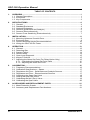
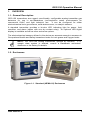
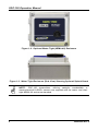
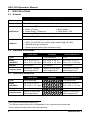
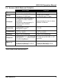
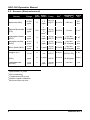
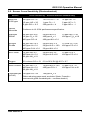
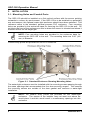
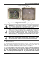
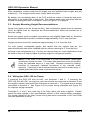
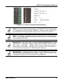
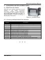
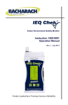
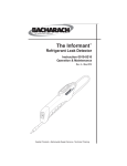
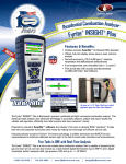
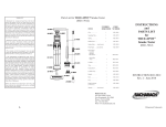
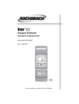
Instruction 5209-9000
Operation Manual
Rev. 0 - May 2011
Product Leadership • Training • Service • Reliability
GDC-150 Operation Manual
IMPORTANT NOTE
READ AND UNDERSTAND THIS MANUAL PRIOR TO USING THIS INSTRUMENT.
THIS INSTRUMENT SHOULD BE INSPECTED
QUALIFIED AND TRAINED PERSONNEL.
AND
PROGRAMMED
BY
THIS INSTRUMENT HAS NOT BEEN DESIGNED TO BE INTRINSICALLY SAFE IN
HAZARDOUS OR EXPLOSION-RATED ENVIRONMENTS. FOR YOUR SAFETY,
DO NOT USE OR INSTALL IT IN AREAS CLASSIFIED AS HAZARDOUS AREAS
(E.G., EXPLOSION-RATED ENVIRONMENTS).
ii
5209-9000 Rev 0
GDC-150 Operation Manual
DISCLAIMER
UNDER NO CIRCUMSTANCES WILL BACHARACH, INC. BE LIABLE FOR ANY
CLAIMS, LOSSES OR DAMAGES RESULTING FROM OR ARISING OUT OF THE
REPAIR OR MODIFICATION OF THIS EQUIPMENT BY A PARTY OTHER THAN
BACHARACH, INC. OR ITS AUTHORIZED SERVICE REPRESENTATIVES, OR BY
OPERATION OR USE OF THE EQUIPMENT OTHER THAN IN ACCORDANCE
WITH THE PRINTED INSTRUCTIONS CONTAINED WITHIN THIS MANUAL OR IF
THE EQUIPMENT HAS BEEN IMPROPERLY MAINTAINED OR SUBJECTED TO
NEGLECT OR ABUSE. ANY OF THE FORGOING WILL VOID THE WARRANTY.
WARRANTY POLICY
BACHARACH, INC. WARRANTS THIS INSTRUMENT TO BE FREE FROM
DEFECTS IN MATERIALS AND WORKMANSHIP FOR A PERIOD OF TWO (2)
YEARS FROM THE DATE OF PURCHASE. THIS INCLUDES ALL ELECTRONICS,
SOLID-STATE SENSORS, CATALYTIC SENSORS, AND ELECTROCHEMICAL
CARBON MONOXIDE (CO) SENSORS. OTHER ELECTROCHEMICAL SENSORS
ARE WARRANTED FOR ONE YEAR.
THE WARRANTY STATUS WILL BE AFFECTED (VOIDED) IF THE INSTRUMENT
HAS NOT BEEN INSTALLED AND MAINTAINED ACCORDING TO THE
INSTRUCTIONS INDICATED IN THIS MANUAL OR HAS BEEN ABUSED,
DAMAGED (ROUGH HANDLING, MECHANICAL DAMAGE, ELECTRICAL SHOCK
DAMAGE, ETC.) OR MODIFIED IN ANY WAY. THIS INSTRUMENT IS ONLY TO BE
USED FOR THE PURPOSES STATED HEREIN. THIS WARRANTY INDICATES
THE FULL EXTENT OF OUR LIABILITY AND WE ARE NOT RESPONSIBLE FOR
REMOVAL
OR
REPLACEMENT
COSTS,
LOCAL
REPAIR
COSTS,
TRANSPORTATION COSTS OR CONTINGENT EXPENSES INCURRED WITHOUT
PRIOR APPROVAL.
BACHARACH, INC. WILL NOT BE HELD LIABLE FOR INDIRECT, INCIDENTAL OR
CONSEQUENTIAL LOSS OR DAMAGE OF ANY KIND TO EQUIPMENT
CONNECTED, IN ANY WAY, TO THE EQUIPMENT MANUFACTURED BY US.
THIS WARRANTY COVERS EQUIPMENT AND PARTS SOLD TO USERS ONLY BY
AUTHORIZED DISTRIBUTORS, DEALERS, AGENTS OR REPRESENTATIVES, AS
AUTHORIZED AND APPOINTED BY BACHARACH.
DUE TO ONGOING RESEARCH, DEVELOPMENT AND PRODUCT TESTING, THE
MANUFACTURER RESERVES THE RIGHT TO CHANGE SPECIFICATIONS
WITHOUT NOTICE. THE INFORMATION CONTAINED HEREIN IS BASED ON
DATA CONSIDERED ACCURATE. HOWEVER, NO WARRANTY IS EXPRESSED
OR IMPLIED REGARDING THE ACCURACY OF THIS DATA.
ALL GOODS MUST BE SHIPPED TO THE MANUFACTURER BY PREPAID
FREIGHT. ALL RETURNED GOODS MUST BE ACCOMPANIED BY AN RMA
NUMBER.
5209-9000 Rev 0
iii
GDC-150 Operation Manual
SERVICE POLICY
BACHARACH, INC. MAINTAINS AN INSTRUMENT SERVICE FACILITY AT THE
FACTORY. SOME BACHARACH DISTRIBUTORS / AGENTS MAY ALSO HAVE
REPAIR FACILITIES, HOWEVER, BACHARACH ASSUMES NO LIABILITY FOR
SERVICE PERFORMED BY ANYONE OTHER THAN BACHARACH PERSONNEL.
REPAIRS ARE WARRANTED FOR 90 DAYS AFTER DATE OF SHIPMENT
(SENSORS, PUMPS, FILTERS AND BATTERIES HAVE INDIVIDUAL
WARRANTIES). SHOULD YOUR INSTRUMENT REQUIRE NON-WARRANTY
REPAIR, YOU MAY CONTACT THE DISTRIBUTOR FROM WHOM IT WAS
PURCHASED OR YOU MAY CONTACT BACHARACH DIRECTLY.
IF BACHARACH IS TO DO THE REPAIR WORK, SEND THE INSTRUMENT,
PREPAID, TO BACHARACH, INC. AT THE FOLLOWING ADDRESS.
BACHARACH, INC.
621 HUNT VALLEY CIRCLE
NEW KENSINGTON, PA 15068
ATTENTION: SERVICE DEPARTMENT
ALWAYS INCLUDE YOUR RMA #, ADDRESS, TELEPHONE NUMBER, CONTACT
NAME, SHIPPING/BILLING INFORMATION AND A DESCRIPTION OF THE
DEFECT AS YOU PERCEIVE IT. YOU WILL BE CONTACTED WITH A COST
ESTIMATE FOR EXPECTED REPAIRS PRIOR TO THE PERFORMANCE OF ANY
SERVICE WORK. FOR LIABILITY REASONS, BACHARACH HAS A POLICY OF
PERFORMING ALL NEEDED REPAIRS TO RESTORE THE INSTRUMENT TO
FULL OPERATING CONDITION.
PRIOR TO SHIPPING EQUIPMENT TO BACHARACH, CONTACT OUR OFFICE
FOR AN RMA # (RETURNED MERCHANDISE AUTHORIZATION).
ALL
RETURNED GOODS MUST BE ACCOMPANIED WITH AN RMA NUMBER.
PACK THE EQUIPMENT WELL (IN ITS ORIGINAL PACKING IF POSSIBLE), AS
BACHARACH CANNOT BE HELD RESPONSIBLE FOR ANY DAMAGE INCURRED
DURING SHIPPING TO OUR FACILITY.
NOTICES
COPYRIGHTS: THIS MANUAL IS SUBJECT TO COPYRIGHT PROTECTION; ALL
RIGHTS ARE RESERVED UNDER INTERNATIONAL AND DOMESTIC
COPYRIGHT LAWS. THIS MANUAL MAY NOT BE COPIED OR TRANSLATED, IN
WHOLE OR IN PART, IN ANY MANNER OR FORMAT, WITHOUT THE WRITTEN
PERMISSION OF BACHARACH, INC.
iv
5209-9000 Rev 0
GDC-150 Operation Manual
REVISIONS
BACHARACH, INC.
MAKES NO WARRANTY OR REPRESENTATION,
EXPRESSED OR IMPLIED INCLUDING ANY WARRANTY OF MERCHANTABILITY
OR FITNESS FOR PURPOSE, WITH RESPECT TO THIS MANUAL.
ALL
INFORMATION CONTAINED IN THIS MANUAL IS BELIEVED TO BE TRUE AND
ACCURATE AT THE TIME OF PRINTING. HOWEVER, BACHARACH RESERVES
THE RIGHT TO MAKE CHANGES AT ANY TIME WITHOUT NOTICE. REVISED
COPIES OF THIS MANUAL CAN BE OBTAINED BY CONTACTING BACHARACH,
INC.
SHOULD YOU DETECT ANY ERRORS OR OMISSIONS IN THIS MANUAL,
PLEASE CONTACT THE COMPANY AT THE FOLLOWING ADDRESS.
BACHARACH, INC.
621 HUNT VALLEY CIRCLE
NEW KENSINGTON, PA 15068-7074
USA
TOLL FREE:
FAX:
E-MAIL:
WEBSITE:
1-800-736-4666
724-334-5001
[email protected]
www.MyBacharach.com
IN NO EVENT WILL BACHARACH, INC., OR ITS OFFICERS OR EMPLOYEES BE
LIABLE FOR ANY DIRECT, SPECIAL, INCIDENTAL, OR CONSEQUENTIAL
DAMAGES RESULTING FROM ANY DEFECT IN ANY MANUAL, EVEN IF ADVISED
OF THE POSSIBILITY OF SUCH DAMAGES.
5209-9000 Rev 0
v
GDC-150 Operation Manual
TABLE OF CONTENTS
1.
OVERVIEW ................................................................................................................ 1
1.1. General Description ............................................................................................ 1
1.2. Enclosures .......................................................................................................... 1
1.3. Key Components ................................................................................................ 3
2.
SPECIFICATIONS ..................................................................................................... 4
2.1. General............................................................................................................... 4
2.2. Standard Enclosures .......................................................................................... 4
2.3. Optional Enclosures............................................................................................ 4
2.4. Sensors (Solid-State and Catalytic) .................................................................... 5
2.5. Sensors (Electrochemical) .................................................................................. 6
2.6. Sensor Cross Sensitivity (Electrochemical) ......................................................... 7
3.
INSTALLATION ......................................................................................................... 8
3.1. Mounting Holes and Conduit Ports...................................................................... 8
3.2. Enclosure Door ................................................................................................... 9
3.3. Sensor Mounting Height Recommendations ......................................................10
3.4. Wiring the GDC-150 for Power ..........................................................................10
4.
OPERATION ............................................................................................................ 13
4.1. General..............................................................................................................13
4.2. Detecting Gas ....................................................................................................14
4.3. System Failure...................................................................................................14
4.4. Sensor Notes .....................................................................................................14
4.5. Open Loop Diagnostic .......................................................................................15
4.6. Jumper Functions ...............................................................................................15
4.7. Adjusting the Alarm Set Point (For Relay Option Only) ......................................15
4.7.1. Calculating the Alarm Set Point Value .................................................... 15
4.7.2. Adjusting the Alarm Set Point................................................................. 16
5.
CALIBRATION ......................................................................................................... 16
5.1. Frequency Recommendations ...........................................................................16
5.2. Calibration Specifications – Gases.....................................................................17
5.3. Regulators and Flow – Solid-State and Catalytic Sensors ..................................17
5.4. Regulators and Flow – Electrochemical Sensors ...............................................17
5.5. Calculating the Span Gas Value ........................................................................18
5.6. Setting the Span Gas Value ...............................................................................19
5.7. Calibrating the Null (Zero) Value ........................................................................19
5.8. Calibrating the Span Value ................................................................................20
6.
ACCESSORIES AND REPLACEMENT PARTS ...................................................... 21
6.1. Metal Protective Guards ....................................................................................21
6.2. Accessory and Replacement Part Numbers .......................................................21
vi
5209-9000 Rev 0
GDC-150 Operation Manual
1.
OVERVIEW
1.1. General Description
GDC-150 transmitters are rugged, user-friendly, configurable analog transmitter gas
detectors for use in non-hazardous (non-explosion rated) environments for
commercial HVAC and light industrial use.
It can be configured for either
electrochemical toxic gas sensors, solid-state sensors, or catalytic sensors.
A standard transmitter provides a bi-color LED indicating light for power, fault
condition, and alarm (option with one dry contact relay). An optional LED digital
display is available as well as other enclosure options.
The electrochemical sensors utilized in this device are accurate enough to measure to
Occupational Health and Safety hazardous levels for toxic gases and oxygen levels.
NOTE: The GDC-150 analog transmitters operate by diffusion. If a
sample draw system is desired, consult a Bacharach authorized
distributor or the factory for details.
1.2. Enclosures
Figure 1-1. Standard (NEMA 1X) Enclosures
5209-9000 Rev 0
1
GDC-150 Operation Manual
Figure 1-2. Optional Water-Tight (NEMA 4X) Enclosure
Figure 1-3. Water-Tight Enclosure (Side View) Showing Optional Splash Guard
NOTE: GDC-150 transmitters utilizing catalytic combustible or
electrochemical H2S/SO2 sensors are supplied with the water- and dusttight NEMA 4X enclosure standard.
2
5209-9000 Rev 0
GDC-150 Operation Manual
1.3. Key Components
Figure 1-4. Key Components on GDC-150 Circuit Board
5209-9000 Rev 0
3
GDC-150 Operation Manual
2.
SPECIFICATIONS
2.1. General
All Sensor Types
Power
12 VAC to 30 VAC or 16 VDC to 30 VDC 1
Current
80 to 120 mA 2
One bi-color LED:
Indicators
• Green = Power
• Red = Alarm
• Flash Green = Warm-up
• Flash Red = Fail
One amber LED (internal relay coil status indicator) 3
One red LED (4-20 mA open-loop indicator for remote transmitter)
Options
• LED digital display (3.5 digits)
• Relay (one SPDT dry contact relay rated 2A @ 30 VAC)
• Water/dust tight enclosure
• Splash guard (water-tight enclosure only)
2.2. Standard Enclosures
Solid-State
Type
Dims
(HxWxD)
PVC
6.5 x 4.4 x 2.5 in
165 x 113 x 65 mm
Catalytic
Polycarbonate
4.9 x 4.9 x 2.9 in
125 x 125 x 75 mm
Electrochemical
PVC
6.5 x 4.4 x 2.5 in
165 x113 x 65 mm
Weight
20 ounces
16 ounces
20 ounces
Construction
Drip-proof overlap
with hinged door
Water- & dust-tight
with hinged door
Drip proof overlap
with hinged door
2.3. Optional Enclosures
Solid-State
Type
Dims
(HxWxD)
Polycarbonate
4.9 x 4.9 x 2.9 in
125 x125 x 75 mm
Catalytic
Electrochemical
Polycarbonate
4.9 x 4.9 x 2.9 in
125 x125 x 75 mm
Weight
16 ounces
16 ounces
Construction
Water- & dust-tight
with hinged door
Water- & dust-tight
with hinged door
1
Non ground referenced supply only
For electro-chemical sensors, this depends on the options that are selected.
3
Only supplied if relay option has been selected
2
4
5209-9000 Rev 0
GDC-150 Operation Manual
2.4. Sensors (Solid-State and Catalytic)
Solid-State
4
4
Catalytic
Type
Solid-state MOS
Range
Combustible: 0-50% LEL
Refrigerant: 0-2000 ppm
Catalytic pellistor
0-100% LEL of target
combustible gas or vapor
Life Span
Combustible: Approximately 5
to 8 years in clean, ambient
conditions
Refrigerant: Approximately 5+
years in clean, ambient
conditions
Approximately 5 years in clean,
ambient conditions
Resolution
Combustible: 1% LEL
Refrigerant: 2 ppm
1% LEL
Temperature
-20°C to +40°C
(-4°F to +104°F)
-20°C to +40°C
(-4°F to +104°F)
Humidity
0-90% non-condensing
0-90% non-condensing
Response
Combustible: T90 = <60 seconds
Refrigerant: T90 = <120 seconds
for most refrigerants
T90 from air to 50% LEL = <12
seconds
Warm-up
2 minute delay
24 hours for best performance
(maximum accuracy)
2 minute delay
1 hour for best performance
(maximum accuracy)
MOS: Metal Oxide Semiconductor
5209-9000 Rev 0
5
GDC-150 Operation Manual
2.5. Sensors (Electrochemical)
Sensor
Range
Life ResoTemp
Span 5 lution
1-2
ppm
RH 6
-40 TO
+50°C 15-90%
Response
Time (T90)
Warm
Up
<90 sec
2-6
hrs
Ammonia (NH3)
0-500
ppm
2
Carbon Monoxide
(CO)
0-200
ppm
5-8
1
ppm,
3
ppm 8
-20 to
10-95%
+50°C
<2 min
1 hr 9
Hydrogen Sulfide
(H2S)
0-50
ppm
3
0.5
ppm
-30 to
15-90%
+50°C
<35 sec
(0-20 ppm)
1 hr9
Nitrogen Dioxide
(NO2)
0-5.0
ppm
3
0.1
ppm
-30 to
15-90%
+50°C
<60 sec
(0-10 ppm)
1-2
hrs
Nitric Oxide (NO)
0-100
ppm
3
1 ppm
-30 to
15-90%
+50°C
<20 sec
(0-50 ppm)
1-2
hrs
Oxygen (O2)
0-25.0
% vol
2
0.1%
vol
-30 to
+50°C
5-95%
<15 sec
(20.9%-0%)
1 hr9
Sulfur Dioxide
(SO2)
0-20
ppm
2
1 ppm
-30 to
15-90%
+50°C
<30 sec
(0-20 ppm)
2 hrs
Formaldehyde
(HCHO)
0-10
ppm
2
0.2
ppm
-20 to
15-90%
+50°C
<80 sec
1 hr
7
5
Approximate, in years
Non-condensing
7
Temperature drift occurs
8
Without regular calibration
9
Minimum warm-up time
6
6
5209-9000 Rev 0
GDC-150 Operation Manual
2.6. Sensor Cross Sensitivity (Electrochemical)
Sensor
Ammonia
0-500 ppm
Carbon
Monoxide
Cross Sensitivity – Electrochemical Sensors Only
300 ppm CO = 8
15 ppm H2S = 30
5 ppm SO2 = -0.5
10% vol CO2 = -15
1 ppm Cl2 = -1
200 ppm H2 = 4
35 ppm NO = 6
5 ppm HCl = -3
5 ppm NO2 = -1
Conforms to UL 2034 performance specification.
Hydrogen
Sulfide
20 ppm SO2 ≤18
10 ppm Cl2 ≤ -25
400 ppm CO ≤ 4
50 ppm NO ≤ 6
400 ppm H2 ≤ 1
400 ppm NH3 ≤ 0.1
10 ppm NO2 ≤ -30
400 ppm C2H4 ≤ 0.8
Nitrogen
Dioxide
50 ppm NO ≤ 0.5
400 ppm H2 ≤ 0.1
400 ppm C2H4 ≤ 0.1
20 ppm SO2 ≤ -2
20 ppm H2S = -100
20 ppm NH3 ≤ 0.1
10 PPM Cl2 = 100
400 ppm CO ≤ 0.1
Nitric Oxide
10 ppm NO2 ≤ 5
400 ppm H2 ≤ 0.1
20 ppm NH3 ≤ 0.1
20 ppm SO2 ≤ 4
20 ppm H2S ≤ 60
10 ppm Cl2 ≤ 5
400 ppm CO ≤ 0.1
Oxygen
5% volume CO2 = 0.1 0% to 95% RH @ 40°C ≤ 0.7
Sulfur Dioxide
50 ppm NO ≤ -3
400 ppm H2 ≤ 0.1
20 ppm NH3 ≤ 0.1
Formaldehyde
(HCHO)
100 ppm CO <18
100 ppm H2 ≤ 3
Other reducing gases such as alcohol (Note: Formalin –
commercial grade formaldehyde – contains alcohol.)
5209-9000 Rev 0
10 ppm NO2 ≤ -100
400 ppm CO ≤ 1
10 ppm Cl2 ≤ -70
400 ppm C2H4 ≤ 40
7
GDC-150 Operation Manual
3.
INSTALLATION
3.1. Mounting Holes and Conduit Ports
The GDC-150 should be installed on a flat vertical surface with the sensor pointing
outwards in a clean, dry environment. If the GDC-150 is to be installed in a potentially
wet environment, the optional water-tight enclosure should have been selected. This
reference refers to the standard, general purpose PVC enclosure. Four mounting
holes are provided in the enclosure base for securing the GDC-150 to the wall. Do
not block the front of the enclosure as this is where the sensor is situated and where it
monitors the air for the target gas.
NOTE: Four mounting holes are provided in the enclosure base for
securing the GDC-150 to the wall. The mounting holes are 3/16″ (4.8
mm) in diameter.
Conduit entry points are provided for the PVC enclosure.
Figure 3-1. Standard Enclosure Showing Mounting Holes
The water-tight enclosure must be installed with the mounting screws passing through
the same openings that accommodate the four door securing screws. This ensures
the mounting screws are outside of the door gasket and confirms a water-tight
installation.
NOTE: No conduit entry points are provided for the water-tight
enclosure. The reason is the installer may not want one where we
would place it and this would result in unnecessary openings into this
enclosure.
8
5209-9000 Rev 0
GDC-150 Operation Manual
Figure 3-2. Water-Tight Enclosure Showing Mounting Holes
WARNING: Do not drill holes in the back of the base of the enclosure
for the purpose of mounting the sensor/transmitter. Leak paths can
occur. Corrosion damage will not be covered under warranty.
NOTE: Use caution when drilling holes in the water-tight enclosure for
conduit entry so as not to damage the circuit board inside. Use liquid
tight conduit hubs wherever conduit enters the water-tight enclosure.
Failure to do so creates a leak path. Water running down the conduit
enters the interior of the enclosure and could corrode the circuit board.
This is not covered under warranty.
NOTE: When mounting either enclosure, allow enough room to enable
the end user to open the door fully to access the internal adjustments.
3.2. Enclosure Door
The standard enclosure has one screw securing the door to the base for electrical
safety and provides an opening to allow the user to apply a zip tie if they desire the
transmitter to be locked more securely. Refer to Figure 1-1 on page 1.
The door of the standard enclosure can be easily removed to facilitate installation of
the base. Simply grasp the lid with one hand, being careful not to make contact with
any of the internal components (circuit board), and grasp the base with your other
hand. Tug on the base, pulling it towards you. The section of the hinges located on
the base should “snap” apart from the part of the hinges located on the door.
5209-9000 Rev 0
9
GDC-150 Operation Manual
After installation, simply locate the lid hinges over the installed base hinges and pull
toward you. The hinges should easily “snap” back into place.
By design, the overlapping door of the PVC enclosure makes it inherently drip proof,
although it is not water tight or dust tight. The optional water-tight enclosure has four
screws for sealing the door to the base. Refer to Figure 1-2 on page 2.
3.3. Sensor Mounting Height Recommendations
Some toxic gases such as ammonia (NH3) and combustible gases such as methane
(CH4) are lighter than air, therefore the sensor/transmitter should be installed on or
near the ceiling.
Some toxic gases such as carbon monoxide are only slightly lighter than air, therefore
the sensor/transmitter should be installed at approximately 4’ to 6’ from the floor.
Oxygen sensors should be installed at approximately 4’ to 6’ from the floor.
For toxic gases, combustible gases, and vapors that are heavier than air, the
sensor/transmitter should be installed with the sensor opening at 6” from the floor.
Although most refrigerants (e.g., Freons) are heavier than air, some applications may
be better suited to a slightly higher mounting height for refrigerant sensors.
NOTE: If the area to be monitored is a wet environment, water-tight
enclosures should be used. The water-tight enclosure must be installed
using the indicated holes or it may leak. Damage caused by leaking
because of improperly installed enclosures is not covered under
warranty. If the area to be monitored has the potential for water spray, a
splash guard should be used to protect the sensor.
3.4. Wiring the GDC-150 for Power
If powering the GDC-150 with 24 VAC, use terminals 1 and 2. If powering the
GDC-150 with 24 VDC, the positive (red) wire should be connected to terminal 2 and
the negative (black) wire should be connected to terminal 3. The signal wire is always
connected to terminal 4. See Figure 3-4 for proper wiring examples and Figure 3-5
for improper wiring examples.
Terminals 5, 6, and 7 are used only if the relay option has been supplied. Double
check the relay ratings in the specifications section of this manual before operation.
For normal operation, the relay control wiring should be connected to N/C and COM
(fail-safe operation is used).
10
5209-9000 Rev 0
GDC-150 Operation Manual
Figure 3-3. Power and Optional Relay Wiring
NOTE: The main wiring terminal strip on the GDC-150 circuit board can
be unplugged for easier wiring installation. Grasp the two sides of the
terminal strip and lift upward with a slight side to side rocking motion.
NOTE: DO NOT use solid-core wire for connection to wiring terminal
strip. Any damage caused by using solid-core wire will void warranty.
Use stranded wire ONLY.
IMPORTANT: The GDC-150 is a low voltage powered device. Any
application of operating voltages higher than indicated in the manual
may result in damage. Double check wiring connections prior to
powering the transmitter. Damage from incorrect wiring connections or
from too much voltage are not covered under warranty.
IMPORTANT: When providing power to the GDC-150, use nongrounded reference supplies only. Refer to Figure 3-4 for proper wiring
examples and Figure 3-5 for improper wiring examples.
5209-9000 Rev 0
11
GDC-150 Operation Manual
Figure 3-4. Proper Wiring Examples
12
5209-9000 Rev 0
GDC-150 Operation Manual
Figure 3-4. Proper Wiring Examples (Continued)
Figure 3-5. Improper Wiring Example
4.
OPERATION
4.1. General
After installation, double check wiring prior to applying power to the GDC-150
transmitter. Remember, these are low voltage devices. After power up, the outer
LED will flash green indicating the system is in a warm-up period. During the warmup period, the signal output from the GDC-150 is fixed at 4.0 mA. If the digital display
option has been fitted, the LED display will indicate a scrolling decimal “…..” until the
warm-up is completed. If the relay option has been selected, the relay is not activated
during warm-up. The GDC-150 has been programmed with a 5-minute warm-up
period. After the warm-up is completed, the signal output and digital display (if this
option has been supplied) will indicate current gas readings (if any).
If the relay option has been supplied, it will have a factory preset alarm set point (this
can easily be changed in the field). In a non-alarm state, the outer LED will be
illuminated green and the amber relay coil inner LED will be illuminated. The
illuminated relay coil LED indicates to the user that the relay coil is energized. The
relay option on the GDC-150 has been designed to operate in a fail-safe manner,
meaning that the relay coil is energized in non-gas-alarm state and de-energize when
a gas alarm is indicated. The device to be controlled should be connected to the N/C
(normally closed) and COM (common) terminals. In the event of a sensor failure,
anything controlled by the relay is activated continuously until the fail condition has
been corrected.
5209-9000 Rev 0
13
GDC-150 Operation Manual
4.2. Detecting Gas
Upon detection of the presence of target gas, the signal output increases to a value
equal to the amount of gas being detected by the sensor. If the LED display option
has been supplied, this value will be displayed. If the concentration of gas is above
the preset alarm threshold, the outer LED changes to red, the alarm relay deenergizes and the amber relay coil LED goes out.
As the detected gas level subsides, the output signal will decrease again to a value
equal to anything being detected by the sensor and this will be indicated on the LED
display (if this option has been selected). The relay will automatically reset after the
signal drops below the set point value.
4.3. System Failure
In the event of a system failure, the outer LED will flash red, the relay will de-energize,
the relay coil LED will go out and the output signal will drop below 4.0 mA. A failure
can consist of a burned out sensor element (solid-state or catalytic), a failed or
damaged component on the circuit board, or a wiring-related problem.
4.4. Sensor Notes
Sensor Type 10
Operation Notes
• Not gas specific
Solid-State
(Refrigerant)
• Respond to a fairly wide range of interfering gases and
vapors
• Temperature and humidity compensated to reduce drift in
environments where these values change regularly
Solid-State
(Combustible)
• Not gas specific, but are less likely to suffer from false
alarms from interfering gases (due to the extremely high
measuring range for which they have been calibrated)
Catalytic
(Combustible)
• Specific to combustible gases and vapors
• Temperature compensated
• These sensors are quite gas specific
Electrochemical
(E.g., Oxygen)
10
14
• Will respond to some other gases (see cross sensitive
gases table on page 7 for more information)
• Temperature compensation to reduce drift in environments
where the temperature changes regularly
Sensors require lengthy warm up and stabilization time after installation. Do not
perform any calibration functions until the sensors have been operating for at least 24
hours.
5209-9000 Rev 0
GDC-150 Operation Manual
4.5. Open Loop Diagnostic
The GDC-150 circuit board has been fitted with a red LED located near the bottom
center of the circuit board. This is an “open loop” indicator and has been designed as
a quick trouble shooting device. If the 4-20 mA signal loop has not been connected
properly or has been damaged in some manner between the analog transmitter and
the device to which it is sending its signal output, this LED illuminates. At this point,
the wiring should be inspected for potential problems.
4.6. Jumper Functions
Figure 4-1. Jumper Functions
4.7. Adjusting the Alarm Set Point (For Relay Option Only)
If the optional relay has been supplied, the alarm set point on the GDC-150 can be
adjusted. The alarm set point value is converted to a voltage in the range of 0-4 VDC.
This voltage range correlates to the full measurement range of the installed sensor.
4.7.1. Calculating the Alarm Set Point Value
Prior to adjusting the alarm set point, calculate the voltage value required using the
following formula.
Example: Catalytic combustible sensors have a standard measurement range of
0-100% LEL. Therefore 4.0 VDC = 100% LEL. Using the values below, 10% of
4.0 VDC = 0.4 VDC. Therefore, the required voltage setting to achieve an alarm set
point of 10% LEL is 0.4 VDC.
5209-9000 Rev 0
15
GDC-150 Operation Manual
Figure 4-2. Calculating the Alarm Set Point
4.7.2. Adjusting the Alarm Set Point
Step
Description
1.
Move the jumper to position P5. The green outer LED will flash once
within 2 seconds for confirmation. The system is now waiting for the user
to set the desired value.
2.
Attach volt meter leads to test points TP1 and TP2 (see Figure 1-4 on
page 3). Alternatively, if the optional LED digital display has been fitted,
read the value indicated on the display.
3.
Use the UP or DOWN push buttons until the calculated voltage is
displayed on the volt meter (or on the optional LED digital display).
4.
Move the jumper back to its resting position (P1). At this time the new
value is saved and the green LED flashes once for confirmation.
5.
CALIBRATION
5.1. Frequency Recommendations
Sensor Types / Applications
Calibration Frequency
Parking garage detectors
Once every 12 months
OHS (Occupational Health and Safety) applications
Once every 6 months
For the purposes of safety in OHS applications, sensors should be gas tested (bump
tested) once every month to confirm response.
Required Equipment:
•
Volt meter
•
Calibration kit
•
Calibration gases.
Users can order the calibration kit, calibration accessories and/or gases from any
Bacharach authorized distributor or they can supply their own gas and equipment as
long as the gas meets the minimum specifications indicated in this manual.
16
5209-9000 Rev 0
GDC-150 Operation Manual
NOTE: It is recommended that a calibration label should be applied after
every calibration to confirm work performed and the date it was
confirmed. If a controller is involved, the alarm set points should be
indicated on a label on the front door of the enclosure so anyone
working in the environment will be aware.
NOTE: For best performance and to ensure the sensor meets the
indicated specifications, all electrochemical sensors should be calibrated
every six months.
The sensors may not perform to the listed
specifications if they are not maintained regularly.
5.2. Calibration Specifications – Gases
Calibration span gases should be at least ±5% accuracy and have a current date
stamp. Gas generators should have a current dated cell installed. Service personnel
should flow zero emissions air or oxygen before attempting to null adjust toxic gas
sensors.
NOTE: For most electrolytic sensors, nitrogen (N2) can be substituted
for zero air. However, for solid-state and catalytic sensors, nitrogen (N2)
should not be substituted for zero air because all solid-state and
catalytic sensors require at least a small volume of Oxygen to operate.
Calibration will be inaccurate.
5.3. Regulators and Flow – Solid-State and Catalytic Sensors
Calibration gases that are lighter than or the same weight as air (CH4, H2, etc.) should
be flowed at 0.5 LPM. Gases heavier than air (C3H8, etc.) should be flowed between
0.5 and 1.0 LPM. Fixed flow regulators provide more accuracy. Gases should be
flowed over the sensor for at least 3 minutes.
The proper calibration adapter should be utilized to allow the gas to properly diffuse
around the sensor. They are available from Bacharach (see table on page 21).
A humidification chamber must be utilized for all solid-state sensors. This is also
available from Bacharach (see table on page 21).
5.4. Regulators and Flow – Electrochemical Sensors
Calibration gases should be flowed at 0.5 LPM. Fixed flow regulators provide more
accuracy. Zero air and span gases should be flowed over the sensor for at least
3 minutes.
The proper calibration adapter should be utilized to allow the gas to properly diffuse
around the sensor. They are available from Bacharach (see table on page 21).
For best performance and to ensure the sensor meets the indicated specifications, all
electrochemical sensors should be calibrated every six months. The sensors may not
perform to the listed specifications if they are not maintained regularly.
5209-9000 Rev 0
17
GDC-150 Operation Manual
5.5. Calculating the Span Gas Value
To achieve calibration the user must first tell the GDC-150 what concentration of span
he is going to flow over the sensor. Within the transmitter, this is a voltage setting.
The range of 0-4 VDC is equal to the full measurement range of the sensor. Prior to
attempting to calibrate, determine the voltage value required.
Use the following formula to calculate the voltage required.
Therefore, in this example, the required voltage setting to calibrate a 0-2000 ppm
sensor with 1000 ppm is 2.0 VDC.
NOTE: When calibrating solid-state sensors for combustibles or
refrigerants, the span gas must be humidified.
The use of a
humidification chamber is required. The humidification chamber sits in
line between the cylinder of span gas and the calibration adapter.
Remove the sponge inside the chamber and wet it under the tap.
Squeeze out the excess water so it is not dripping wet and place it back
inside the chamber. As gas flows through the chamber, it absorbs water
which acts to humidify it and the humidified span gas flows over the
sensor. See page 21 for ordering information.
NOTE: Values for Calibration Span Gas and Sensor Range in the
above equations must have the same Engineering Units (e.g., PPM, %
of LEL, % vol, etc.).
18
5209-9000 Rev 0
GDC-150 Operation Manual
5.6. Setting the Span Gas Value
Step
Setting the Span Gas Value Procedure
1
Move the jumper to position P2 (see Figure 4-1 on page 15). The green
outer LED flashes once for confirmation. The system is now waiting for
the user to set the desired value.
2
Attach volt meter leads to test points TP1 and TP2 (see Figure 1-4 on
page 3). Alternatively, if the optional LED digital display has been fitted,
read the value indicated on the display.
3
Use the UP or DOWN push-buttons (see Figure 1-4 on page 3) until the
calculated voltage is displayed on the volt meter (or the optional LED
digital display).
4
Move the jumper back to its resting position (P1). At this time the new
value is saved and the green LED flashes once for confirmation.
5.7. Calibrating the Null (Zero) Value
Step
Calibrating the Null (Zero) Value Procedure
1
Attach a regulator to a cylinder of zero air (or nitrogen).
2
Insert the calibration adapter into the sensor opening in the front of the
enclosure door. Use a slight twisting motion as you gently push the
calibration adapter into the sensor opening. If the calibration adapter is
hard to insert, moisten the "O" ring slightly then try re-inserting it. If the
transmitter has been fitted with an optional splash guard, remove the
plastic plug from the center of the splash guard to gain access to the
sensor opening. To remove the plastic plug, push inward at the center of
the plug until the edges lift slightly then slip a small flat blade screwdriver
under and pop the plug off.
3
Open the regulator valve fully and allow zero air to flow over sensor.
4
Move the jumper to position P3 (see Figure 4-1 on page 15). The outer
LED will change to a steady amber color. The system now waits 30
seconds to ensure the user is flowing zero air.
The GDC-150 then enters a count down during which time it adjusts the
null value. The length of this count down period is:
•
90 seconds for catalytic and solid-state sensors
5
6
•
60 seconds for electrochemical sensors.
If desired, attach the volt meter leads to test points TP1 and TP2 (see
Figure 1-4 on page 3). The meter will show 0.0 VDC, climb to a higher
value, then slowly descend back to 0.0 VDC indicating the GDC-150 has
null adjusted the circuit. Once the count down is finished, the outer LED
changes back to green indicating the procedure is complete.
Move the jumper back to its resting position (P1) and remove the zero air.
5209-9000 Rev 0
19
GDC-150 Operation Manual
IMPORTANT: If the user attempts to null adjust the sensor without
applying zero air and the sensor detects background gas the amber
LED flashes to advise the user that it is out of tolerance.
5.8. Calibrating the Span Value
Step
Calibrating the Span Value Procedure
1
Attach regulator to cylinder of span gas.
2
Insert the calibration adapter into the sensor opening in the front of the
enclosure door. Use a slight twisting motion as you gently push the
calibration adapter into the sensor opening. If the calibration adapter is
hard to insert, moisten the “o” ring seal slightly then try re-inserting it.
3
Open regulator valve fully and allow span gas to flow over sensor.
4
Move the jumper to J4 position (see Figure 4-1 on page 15). The tri-color
outer LED will change to a steady amber color. The system now waits 30
seconds to ensure the user is flowing span gas.
5
The GDC-150 then enters a count down (180 seconds for catalytic and
solid-state sensors, 150 seconds for Electrochemical sensors) during
which time it adjusts the circuit to the span value which was set earlier
(see “Setting the Span Gas Value”).
If the user wishes to view this, attach meter leads to test points TP1 and
TP2 (see Figure 1-4 on page 3). The meter will show an increasing
voltage indicating the GDC-150 sensor is responding to the span gas and
the circuit is being adjusted for accuracy. Alternatively, If the optional
LED digital display has been fitted, read the value indicated on the outer
digital display. Once the count down is finished, the outer LED changes
back to green indicating the procedure is complete.
6
Before removing the span gas, move the jumper back to its resting
position (J1) and the new value is saved.
IMPORTANT: If the user attempts to span adjust the sensor without
applying span gas or the proper value of span gas, the sensor will
produce a response that is outside of the circuit preset tolerance value.
The amber LED flashes to advise the user that it is out of tolerance.
20
5209-9000 Rev 0
GDC-150 Operation Manual
6.
ACCESSORIES AND REPLACEMENT PARTS
6.1. Metal Protective Guards
GDC-150 series analog transmitters are all
supplied in very rugged, non-metallic
enclosures. However, in some applications
more protection may be desired. Bacharach
can provide protective guards made from 16
gauge galvanized metal with a pattern of
square perforations to permit air and gas to
diffuse easily to the sensor.
Figure 6-1. Protective Guard
6.2. Accessory and Replacement Part Numbers
Part
Number
Description
5209-0002
LED digital display (must be selected when ordering)
5209-0003
Relay (rated 2A @ 30 VAC)
5209-0005
Water- and dust-tight NEMA 4X enclosure
5209-0004
Splash guard (NEMA 4X enclosure only)
5209-0006
Calibration adapter for all other sensors
5209-0016
Calibration adapter for catalytic sensors
5209-0017
Sample draw pump (24 VAC-powered)
5209-0018
Sample draw pump (24 VDC-powered)
5209-0019
Transmitter guard (16 gauge galvanized metal)
5209-0021
Humidification chamber (for calibration of solid-state sensors)
∇ ∇ ∇
5209-9000 Rev 0
21
GDC-150 Operation Manual
World Headquarters
621 Hunt Valley Circle, New Kensington, Pennsylvania 15068
Phone: 724-334-5000 • Toll Free: 1-800-736-4666 • Fax: 724-334-5001
Website: www.MyBacharach.com • E-mail: [email protected]
22
5209-9000 Rev 0