1
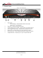
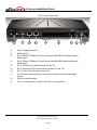
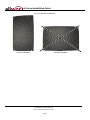
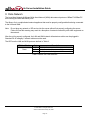
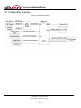
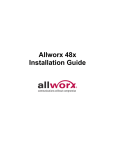
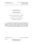
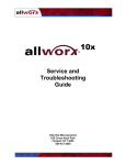
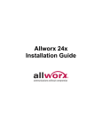
Allworx® 6x Server
Installation Guide
No part of this publication may be reproduced, stored in a retrieval system, or transmitted, in any
form or by any means, electronic, mechanical, photocopy, recording, or otherwise without the prior
written permission of Allworx.
© 2009 Allworx Corp, a wholly owned subsidiary of PAETEC Holding Corp. All rights reserved. Allworx is a
registered trademark of Allworx Corp. All other names may be trademarks or registered trademarks of their
respective owners.
6x Server Installation Guide
Table of Contents
Table of Contents ................................................................................................................................................i
1 Installation Overview .....................................................................................................................................1
2 Unpacking .....................................................................................................................................................1
3 Chassis Views ...............................................................................................................................................2
4 Mechanical ....................................................................................................................................................4
4.1 Tabletop or Shelf Placement.......................................................................................................................4
4.2 Wall Mount ..................................................................................................................................................4
5 Electrical........................................................................................................................................................6
5.1 Chassis Ground ..........................................................................................................................................6
5.2 Power-Up Sequence ...................................................................................................................................6
5.3 Safe Mode Sequence..................................................................................................................................6
6 Accessories (Optional) ..................................................................................................................................7
6.1 Music-On-Hold ............................................................................................................................................7
6.2 Overhead Paging ........................................................................................................................................7
6.3 USB External Hard Drive ............................................................................................................................7
6.4 Compact Flash Cards .................................................................................................................................7
6.5 Door Relay/Paging Amplifier/Diagnostic Port..............................................................................................8
7 Configuring Handsets and Lines .................................................................................................................10
7.1 Analog .......................................................................................................................................................10
7.2 SIP ............................................................................................................................................................10
8 Server Configuration ...................................................................................................................................11
9 Data Network...............................................................................................................................................12
10 Configuration Example ................................................................................................................................13
11 Physical and Environmental Specifications.................................................................................................14
12 Regulatory Notices ......................................................................................................................................15
12.1 Lithium Battery ........................................................................................................................................15
12.2 FCC Part 68 ............................................................................................................................................15
12.3 Industry Canada......................................................................................................................................16
12.4 Radio and Television Interference ..........................................................................................................16
13 Wall Mount Template ..................................................................................................................................18
300 Main Street • East Rochester, NY 14445 • Toll Free 1-866-ALLWORX • 585-421-3850 • www.allworx.com
© 2009 Allworx. All rights reserved
Version 2. Revised: January 26, 2009
Page i
6x Server Installation Guide
1 Installation Overview
Installation of the Allworx 6x server involves the following steps:
1. Unpacking
2. Mechanical Installation
3. Electrical Installation
4. Accessories Installation
5. Telephony Installation
6. Server Configuration
7. Network Installation
Each of these steps will be described in the following sections.
300 Main Street • East Rochester, NY 14445 • Toll Free 1-866-ALLWORX • 585-421-3850 • www.allworx.com
© 2009 Allworx. All rights reserved
Version 2. Revised: January 26, 2009
Page 1
6x Server Installation Guide
2 Unpacking
Open the box and carefully unpack it. Save all shipping and packaging materials. Verify all items against the
parts list shown in Table 1. If any items are missing, contact your dealer or Allworx Customer Support at 866255-9679.
Quantity
1
1
1
1
1
Item
Allworx 6x Server
Power Adapter (12 VDC @ 1A)
6x Installation Instructions
Sheet of 4 Rubber Feet
Compact Flash Card (installed in server)
Table 1: Parts List
300 Main Street • East Rochester, NY 14445 • Toll Free 1-866-ALLWORX • 585-421-3850 • www.allworx.com
© 2009 Allworx. All rights reserved
Version 2. Revised: January 26, 2009
Page 1
6x Server Installation Guide
3 Chassis Views
Figure 1: Front Chassis View
1
2
3
4
5
6
1
Power switch
Press & Release – Normal shutdown within a few seconds
Press & Hold – Forced shutdown
2
Power LED – Indicates system start up activity
3
Outside Analog Phone Line LEDs – Indicates status of a particular FXO port
4
Inside Analog Extension LEDs – Indicates status of a particular FXS port
5
Network LEDs – Indicates Ethernet link status; flashes off for activity
6
Drive Activity LEDs – Green indicates mounted drive; flashes off for activity
7
Compact Flash Slot – Accepts Type I or Type II Compact Flash Card
7
300 Main Street • East Rochester, NY 14445 • Toll Free 1-866-ALLWORX • 585-421-3850 • www.allworx.com
© 2009 Allworx. All rights reserved
Version 2. Revised: January 26, 2009
Page 2
6x Server Installation Guide
Figure 2: Rear Chassis View
8
9
10
11
12
13
14
15
8
Door and paging relay port
9
USB Host Port
10
RJ-45 10BaseT/100BaseTX Auto-Sensing Auto-MDI/MDIX Local Area Network
Ethernet port.
11
RJ-45 10BaseT/100BaseTX Auto-Sensing Auto-MDI/MDIX Wide Area Network
Ethernet port.
12
RJ-11 FXS ports for inside extensions (Ports 7-8)
13
RJ-11 loop-start FXO for central office connection (Ports 1-6)
14
RJ-11 Power Fail analog phone connector
15
3.5 mm stereo audio mini jack for music-on-hold (input) and overhead paging
(output)
16
Ground connecting screw
17
5.5 x 2.1 mm power jack. Input 12 VDC @ 1A, center positive
300 Main Street • East Rochester, NY 14445 • Toll Free 1-866-ALLWORX • 585-421-3850 • www.allworx.com
© 2009 Allworx. All rights reserved
Version 2. Revised: January 26, 2009
Page 3
16
17
6x Server Installation Guide
4 Mechanical
4.1 Tabletop or Shelf Placement
To install the Allworx 6x on a tabletop or shelf:
1. Remove the four rubber feet from the packaging.
2. Turn over the chassis and notice the triangle on each corner (2 large triangles in front, 2 smaller in back).
3. Remove the paper backing from each rubber foot and place one foot in each triangle.
4.2 Wall Mount
To mount the Allworx 6x on ½” drywall:
1. Verify that there is sufficient clearance around the server’s front and rear panels to allow power, network,
and telephony connections.
2. Use self-drilling drywall anchors rated for at least 20 lbs with screws that are either #6 or #8. Locate two
anchors that will support the upper end of the unit using the wall mount template included in Section 13.
Install the anchors per the anchor manufacturer’s recommendation. Install the mounting screws into the
anchors leaving approximately 1/8” between the bottom of the screw head and the wall.
3. Slide unit onto mounting screws. Adjust screw height if necessary to insure a snug fit against the wall.
Caution: The Allworx server must be securely mounted to the wall to avoid equipment damage or
personal injury.
Note: The unit must be mounted with the front facing forward, not up or down (see Figure 3).
300 Main Street • East Rochester, NY 14445 • Toll Free 1-866-ALLWORX • 585-421-3850 • www.allworx.com
© 2009 Allworx. All rights reserved
Version 2. Revised: January 26, 2009
Page 4
6x Server Installation Guide
Figure 3: Wall Mount Orientation
Correct Orientation
Wrong Orientation
300 Main Street • East Rochester, NY 14445 • Toll Free 1-866-ALLWORX • 585-421-3850 • www.allworx.com
© 2009 Allworx. All rights reserved
Version 2. Revised: January 26, 2009
Page 5
6x Server Installation Guide
5 Electrical
5.1 Chassis Ground
Warning: Failure to follow these steps may result in equipment damage, personal injury, and void the
product warranty.
To help prevent electrical shock, the separate protective earthing terminal located next to the power jack on the
rear panel must be permanently connected to earth using 18 AWG wire or larger. (See Figure 2 item 16)
5.2 Power-Up Sequence
Connect the unit to the power source with the AC power adapter. The server will automatically begin to power
up. As it progresses through the power up sequence, the front panel lights will respond as shown in Table 2.
Front Panel Light
Power
Drive Activity – CF
Power-Up Sequence Description
Flashes green as the power up sequence
progresses; lights steady green when the unit is
ready.
Flashes green when drive mounted; flashes off for
activity.
Table 2: Front Panel Lights During Power-Up Sequence
5.3 Safe Mode Sequence
When the unit is off, if the power button is held greater than 1 second when turning the unit on, the power light
will change from Green to Amber indicating that the unit will start in Safe Mode. Once the power button is
released the, the power button will change to Red very briefly indicating that the reset sequence has begun.
Once the 6x is in Safe Mode, the front panel lights will be displayed as shown in Table 3.
Front Panel Light
Power
Drive Activity – CF
Line Interface Indicators
Safe Mode Light Description
Solid Amber
Off
Solid Amber
Table 3: Front Panel Lights in Safe Mode
300 Main Street • East Rochester, NY 14445 • Toll Free 1-866-ALLWORX • 585-421-3850 • www.allworx.com
© 2009 Allworx. All rights reserved
Version 2. Revised: January 26, 2009
Page 6
6x Server Installation Guide
6 Accessories (Optional)
Note: A stereo splitter (not included) is required to use both Music-On-Hold and Overhead Paging together.
6.1 Music-On-Hold
Connect the output from your music system to the server using a 3.5mm stereo plug line-in audio adapter
cable. Insert the male cable end into the audio connector labeled Audio on the rear panel (See Figure 2 item
15).
Note: Only the white audio channel is used for music input. Red channel is for paging output (see Figure 4).
Figure 4: Audio Plug Diagram
Line In
GND
Line Out
6.2 Overhead Paging
Connect the server to the input of your paging system using a 3.5mm stereo plug audio cable. Insert the male
cable end into the audio connector labeled Audio on the rear panel (See Figure 2 item 15). Only the red audio
channel is used.
Note: Only the red audio channel is used for paging output. White channel is for hold input (see Figure 4).
6.3 USB External Hard Drive
To install a USB External Hard Drive:
1. Plug the USB data cable from the external hard drive into the USB port on the server and power on the
USB drive. (See Figure 2 item 9).
2. Restart the server into Safe Mode.
3. In Safe Mode select Convert under Disk Operations.
4. Once the conversion is complete, power down the server.
5. Remove the Compact Flash.
6. Power on the system. Your hard drive should now be ready to use.
Note: Must use USB 2.0 based IDE hard drive directly plugged into unit (do not use with hub).
6.4 Compact Flash Cards
Unit comes pre-installed with a 512MB flash card. This card provides for approximately 800 minutes of
voicemail storage. If more space is desired, use the USB External Hard Drive option (see section 6.3) or
300 Main Street • East Rochester, NY 14445 • Toll Free 1-866-ALLWORX • 585-421-3850 • www.allworx.com
© 2009 Allworx. All rights reserved
Version 2. Revised: January 26, 2009
Page 7
6x Server Installation Guide
substitute the 512MB flash card provided with a larger capacity compact flash card prior to initial configuration.
The unit is compatible with SanDisk Ultra® II CompactFlash® cards that support DMA capability.
To install a new Compact Flash card:
1. With the power off, insert the new CompactFlash card into the compact flash slot on the server (See Figure
1 item 7). Make sure that the CompactFlash card is inserted securely to prevent spurious interrupt
messages that can occur when the CompactFlash card is just touching the connectors.
2. Power on the server (note it will boot into Safe Mode).
3. Set up the PC’s network interface to obtain an IP address automatically (using DHCP).
4. You may need to release and renew the PC’s IP address to get an address from the server.
5. Verify that the PC has an IP address on the 192.168.2.xxx network.
6. Open your browser and enter the URL of http://192.168.2.254:8080 or current IP address.
7. In Safe Mode select Format under Disk Operations.
8. Click OK to format.
9. Enter the word yes format when prompted.
10. Once the formatting is complete, perform a software update.
11. Once the software update is complete reboot normal mode.
12. Your new Compact Flash card should now be ready to use.
To remove a Compact Flash card:
1. Grasp the center of the card with thumb and index finger.
2. Tug forward gently.
6.5 Door Relay/Paging Amplifier/Diagnostic Port
Unit comes with a single set of C-form relay contacts for connecting to external devices such as remote door
releases and amplifiers. The contacts are rated 30 VDC @ 1A.
Warning: Do not exceed the contact rating.
300 Main Street • East Rochester, NY 14445 • Toll Free 1-866-ALLWORX • 585-421-3850 • www.allworx.com
© 2009 Allworx. All rights reserved
Version 2. Revised: January 26, 2009
Page 8
6x Server Installation Guide
The connector is shared with the serial port (See Figure 2 item 8). The pinout is shown in Table 4 below.
Pin
2 (do not connect)
3 (do not connect)
5 (do not connect)
9
6
1
Signal
RX
TX
GND
Relay COM
Relay NC
Relay NO
Direction
Input
Output
-----
Table 4: Door Relay Pinout
Should Allworx Customer Support instruct you to capture diagnostic data, connect a null modem serial cable
from the Door and Paging Relay connector to the serial port on a PC. Configure the PC port in accordance with
the following table:
Baud
Data Bits
Parity
Stop Bits
Flow Control
9600
8
None
1
None
Table 5: Serial Port Configuration
To configure the door relay/paging amplifier:
1. Open your browser and enter the URL of http://192.168.2.254:8080 or current IP address.
2. In the Phone System group select Paging.
3. Click Modify in the Page Amplifier area.
4. Select DB9 is connected to a Door Entry System to enable door relay or Paging Amplifier to enable
amplifier.
5. Click Update.
To activate the door relay:
1. From any handset connected to the system dial extension 403.
300 Main Street • East Rochester, NY 14445 • Toll Free 1-866-ALLWORX • 585-421-3850 • www.allworx.com
© 2009 Allworx. All rights reserved
Version 2. Revised: January 26, 2009
Page 9
6x Server Installation Guide
7 Configuring Handsets and Lines
7.1 Analog
Caution: To reduce the risk of fire, use only 26 AWG (or larger) UL listed or CSA certified
telecommunications line cord.
The server’s analog phone connections can be used to connect Central Office (CO) lines or telephone
handsets. Table 6 describes the ports.
RJ-11 Ports
Type
1-6
FXO (loop-start)
7-8
FXS
Description
Used to connect to Central Office (CO) lines
Telephone handsets
Table 6: Analog Telephony Ports
It is recommended that the ports be connected as follows:
•
CO Lines: Begin with port 1 and move up.
•
Telephone Handsets: Begin with port 8 and move down.
The Power Fail Phone port may be used to connect an analog phone device that is operational in the event
that the server loses power or fails. During power failure, it automatically connects to the first outside phone
line port (port 1).
Surge protection is provided internally on all telephony interfaces.
Under normal operation of the unit the port LEDs will appear as shown in Table 7.
Port (1-8) State
Normal Idle
Off Hook
Ringing
No loop current detected on last off
hook attempt (FXO only)
LED Indicator
Off
Green Solid
Green Fast Blink
Alternating Red/Amber
Table 7: Analog Port LED Definitions
7.2 SIP
Allworx and 3rd-party SIP handsets connect to the server through the site’s network to the 6x LAN port. See
Section 8, Server Configuration and Section 9, Data Network for more information.
The Allworx 6x supports SIP trunks for outside line services. Refer to the Allworx System Administrator’s Guide
for information on configuring SIP trunks. In addition, application notes for configuring SIP trunks provided by
Allworx Internet Telephony Service Provider (ITSP) partners are available on the Allworx Reseller’s Portal at
www.allworx.com.
300 Main Street • East Rochester, NY 14445 • Toll Free 1-866-ALLWORX • 585-421-3850 • www.allworx.com
© 2009 Allworx. All rights reserved
Version 2. Revised: January 26, 2009
Page 10
6x Server Installation Guide
8 Server Configuration
The Allworx 6x provides an administrative interface to configure and administer the server. The administrative
interface is accessed using a web browser. Assuming the network settings are set to their factory defaults, the
steps to connect to this interface are:
1. Plug your PC directly into the LAN port.
2. Set up the PC’s network interface to obtain an IP address automatically (using DHCP).
3. You may need to release and renew the PC’s IP address to get an address from the server.
4. Verify that the PC has an IP address on the 192.168.2.xxx network.
5. Open your browser and enter the URL of http://192.168.2.254:8080 or current IP address.
6. When the Welcome to Allworx page appears, login using the default password of admin.
When the Home page appears, click on the Install Checklist link (on the left hand side) to bring up a new
window containing steps necessary to set up a new system. Each brief step description is followed by a link to
get to the appropriate administrative web page to execute the step. These steps are ordered to aid in a
successful configuration. Most of the web pages to execute each step contain all the descriptions and help
necessary to carry out the step. Use the Allworx System Administrator’s Guide to supplement the information
on the web pages, when necessary.
If the server has been previously configured for another installation, you should restore it to its factory default
configuration. This can be done by:
1. Rebooting the server to Safe Mode.
2. Format the disk and perform a Software Update (see Allworx System Administration Guide for instructions).
300 Main Street • East Rochester, NY 14445 • Toll Free 1-866-ALLWORX • 585-421-3850 • www.allworx.com
© 2009 Allworx. All rights reserved
Version 2. Revised: January 26, 2009
Page 11
6x Server Installation Guide
9 Data Network
The Local Area Network (LAN) and Wide Area Network (WAN) data network ports are 10BaseT/100BaseTX
auto-sensing and auto-MDI/MDIX ports.
The Allworx 6x is a sophisticated network appliance that must be properly configured before being connected
to the LAN and WAN.
Note:
Do not plug any network or ISP service into the server without first properly configuring the server.
Failure to heed this warning may result in a disruption of network connectivity with other equipment on
the network.
After the unit is properly configured, the LAN and WAN network infrastructure cables can be plugged in.
Standard RJ-45 category 5 network cables must be used.
The LED’s on the LAN and WAN ports are defined in Table 8.
LED Identification
Green
State
Description
Off
No link: the network is not connected
On
Link: the network is successfully connected
Blinking Activity: data is being transmitted or received
Table 8: Network Port LED Definitions
300 Main Street • East Rochester, NY 14445 • Toll Free 1-866-ALLWORX • 585-421-3850 • www.allworx.com
© 2009 Allworx. All rights reserved
Version 2. Revised: January 26, 2009
Page 12
6x Server Installation Guide
10 Configuration Example
Figure 5: Configuration Example
300 Main Street • East Rochester, NY 14445 • Toll Free 1-866-ALLWORX • 585-421-3850 • www.allworx.com
© 2009 Allworx. All rights reserved
Version 2. Revised: January 26, 2009
Page 13
6x Server Installation Guide
11 Physical and Environmental Specifications
Dimensions (W x H x D)
Weight (Base Model)
Power
Temperature
Humidity
12.1 x 1.9 x 7.6 inches (30.8 x 4.8 x 19.3 cm)
3 lbs
DC 12V, 1 Amp.
0° ~ 40° C
15% ~ 90% RH, Non-condensing
Table 9: Physical and Environmental Specifications
300 Main Street • East Rochester, NY 14445 • Toll Free 1-866-ALLWORX • 585-421-3850 • www.allworx.com
© 2009 Allworx. All rights reserved
Version 2. Revised: January 26, 2009
Page 14
6x Server Installation Guide
12 Regulatory Notices
12.1 Lithium Battery
Caution: Risk of explosion if the battery is replaced by an incorrect type.
•
Disposal of lithium batteries should be done in accordance with applicable federal, state, and local
regulations.
•
Batteries should not be incinerated, unless suitable procedures are followed and qualified handlers
have taken appropriate precautions. Exposure of these cells to high temperatures or fire can cause the
cells to vent and/or rupture.
•
Handling of used batteries should be done according to the safety instructions of fresh batteries.
•
Recycling of batteries should be done in authorized facilities, through licensed waste carriers.
12.2 FCC Part 68
This equipment complies with Part 68 of FCC rules and the requirements adopted by ACTA. On the backside
of this equipment is a label that contains, among other information, a product identifier in the format US:
AAAEQ##TXXXX. If requested, provide this number to the telephone company.
A plug and jack used to connect this equipment to the premises wiring and telephone network must comply
with the applicable FCC Part 68 rules and requirements adopted by the ACTA. See installation instructions for
details.
The REN is used to determine the number of devices that may be connected to a telephone line. Excessive
RENs on a telephone line may result in the devices not ringing in response to an incoming call. In most but not
all areas, the sum of RENs should not exceed five (5.0). To be certain of the number of devices that may be
connected to a line, as determined by the total RENs, contact the local telephone company. For products
approved after July 23, 2001, the REN for this product is part of the product identifier that has the format
US:AAAEQ##TXXXX. The digits represented by ## are the REN without a decimal point (e.g., 03 is a REN of
0.3). For earlier products, the REN is separately shown on the label.
If this equipment causes harm to the telephone network, the telephone company will notify you in advance that
temporary discontinuance of service may be required. But if advance notice isn't practical, the telephone
company will notify the customer as soon as possible. Also, you will be advised of your right to file a complaint
with the FCC if you believe it is necessary.
The telephone company may make changes in its facilities, equipment, operations or procedures that could
affect the operation of the equipment. If this happens, the telephone company will provide advance notice in
order for you to make necessary modifications to maintain uninterrupted service.
If trouble is experienced with this equipment, for repair or warranty information, please contact our company. If
the equipment is causing harm to the telephone network, the telephone company may request that you
disconnect the equipment until the problem is resolved.
300 Main Street • East Rochester, NY 14445 • Toll Free 1-866-ALLWORX • 585-421-3850 • www.allworx.com
© 2009 Allworx. All rights reserved
Version 2. Revised: January 26, 2009
Page 15
6x Server Installation Guide
12.3 Industry Canada
The Industry Canada label identifies certified equipment. This certification means that the equipment meets
telecommunications network protective, operation and safety requirements as prescribed in the appropriate
Terminal Equipment Technical Requirements document(s). The Department does not guarantee the
equipment will operate to the user's satisfaction. Before installing this equipment, users should ensure that it is
permissible to be connected to the facilities of the local telecommunications company. The equipment must
also be installed using and acceptable method of connection. The customer should be aware that compliance
with the above conditions might not prevent degradation of service in some situations.
Repairs to certified equipment should be coordinated by a representative designated by the supplier. Any
repairs or alterations made by the user to this equipment, or equipment malfunctions, may give the
telecommunications company cause to request the user to disconnect the equipment.
Users should ensure for their own protection that the electrical ground connections of the power utility,
telephone lines and internal metallic water pipe system, if present, are connected together. This precaution
may be particularly important in rural areas.
Caution: Users should not attempt to make such connections themselves, but should contact the
appropriate electric inspection authority, or electrician, as appropriate.
NOTICE: This equipment meets the applicable Industry Canada Terminal Equipment Technical Specifications.
This is confirmed by the registration number. The abbreviation, IC, before the registration number signifies that
registration was performed based on a Declaration of Conformity indicating that Industry Canada technical
specifications were met. It does not imply that Industry Canada approved the equipment.
AVIS: Le présent matériel est conforme aux spécifications techniques d’Industrie Canada applicables au
matériel terminal. Cette conformité est confirmée par le numéro d'enregistrement. Le sigle IC, placé devant le
numéro d'enregistrement, signifie que l’enregistrement s’est effectué conformément à une déclaration de
conformité et indique que les spécifications techniques d'Industrie Canada ont été respectées. Il n’implique pas
qu’Industrie Canada a approuvé le matériel.
NOTICE: The Ringer Equivalence Number (REN) for this terminal equipment is 0.1. The REN assigned to
each terminal device provides an indication of the maximum number of terminals allowed to be connected to a
telephone interface. The termination on an interface may consist of any combination of devices subject only to
the requirement that the sum of the Ringer Equivalence Numbers of all the devices does not exceed 5.
AVIS : L'indice d'équivalence de la sonnerie (IES) du présent matériel est de 0.1. L'IES assigné à chaque
dispositif terminal indique le nombre maximal de terminaux qui peuvent être raccordés à une interface
téléphonique. La terminaison d'une interface peut consister en une combinaison quelconque de dispositifs, à la
seule condition que la somme d'indices d'équivalence de la sonnerie de tous les dispositifs n'excède pas 5.
12.4 Radio and Television Interference
This equipment has been tested and found to comply with the limits for a Class A digital device, pursuant to
Part 15 of the FCC rules. These limits are designed to provide reasonable protection against harmful
interference in a residential installation. This equipment generates uses and can radiate radio frequency
energy and, if not installed and used in accordance with the instructions, may cause harmful interference to
radio communications. There is no guarantee, however, that interference will not occur in a particular
300 Main Street • East Rochester, NY 14445 • Toll Free 1-866-ALLWORX • 585-421-3850 • www.allworx.com
© 2009 Allworx. All rights reserved
Version 2. Revised: January 26, 2009
Page 16
6x Server Installation Guide
installation. If this equipment does cause harmful interference to radio or television reception, which can be
determined by turning the equipment off and on, the user is encouraged to try to correct the interference by
one or more of the following measures:
•
Reorient or relocate the receiving antenna.
•
Increase the separation between the equipment and the receiver.
•
Connect the equipment into an outlet on a circuit different from that to which the receiver is connected.
•
Consult the dealer or an experienced radio/TV technician for help.
You may also find helpful the following booklet, prepared by the FCC: "How to Identify and Resolve Radio-TV
Interference Problems.” This booklet is available from the U.S. Government Printing Office, Washington D.C.
20402.
Changes and Modifications not expressly approved by the manufacturer or registrant of this equipment can
void your authority to operate this equipment under Federal Communications Commissions rules.
This digital apparatus does not exceed the Class A limits for radio noise emissions from digital apparatus set
out in the Radio Interference Regulations of the Canadian Department of Communications.
Le présent appareil numérique n'emet pas de bruits radioélectriques depassant les limites applicables aux
appareils numérique de la class A préscrites dans le Règlement sur le brouillage radioélectrique édicte par le
Ministere des Communications du Canada.
300 Main Street • East Rochester, NY 14445 • Toll Free 1-866-ALLWORX • 585-421-3850 • www.allworx.com
© 2009 Allworx. All rights reserved
Version 2. Revised: January 26, 2009
Page 17
6x Server Installation Guide
13 Wall Mount Template
300 Main Street • East Rochester, NY 14445 • Toll Free 1-866-ALLWORX • 585-421-3850 • www.allworx.com
© 2009 Allworx. All rights reserved
Version 2. Revised: January 26, 2009
Page 18