1
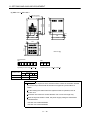
General-Purpose AC Servo
J3 Series
SSCNET
Compatible
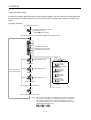
MODEL
MR-J3- B
SERVO AMPLIFIER
INSTRUCTION MANUAL
B
Safety Instructions
(Always read these instructions before using the equipment.)
Do not attempt to install, operate, maintain or inspect the servo amplifier and servo motor until you have read
through this Instruction Manual, Installation guide, Servo motor Instruction Manual and appended documents
carefully and can use the equipment correctly. Do not use the servo amplifier and servo motor until you have a
full knowledge of the equipment, safety information and instructions.
In this Instruction Manual, the safety instruction levels are classified into "WARNING" and "CAUTION".
WARNING
Indicates that incorrect handling may cause hazardous conditions,
resulting in death or severe injury.
CAUTION
Indicates that incorrect handling may cause hazardous conditions,
resulting in medium or slight injury to personnel or may cause physical
damage.
Note that the CAUTION level may lead to a serious consequence according to conditions. Please follow the
instructions of both levels because they are important to personnel safety.
What must not be done and what must be done are indicated by the following diagrammatic symbols:
: Indicates what must not be done. For example, "No Fire" is indicated by
: Indicates what must be done. For example, grounding is indicated by
.
.
In this Instruction Manual, instructions at a lower level than the above, instructions for other functions, and so
on are classified into "POINT".
After reading this installation guide, always keep it accessible to the operator.
A- 1
1. To prevent electric shock, note the following:
WARNING
Before wiring or inspection, switch power off and wait for more than 15 minutes. Then, confirm the voltage
is safe with voltage tester. Otherwise, you may get an electric shock.
Connect the servo amplifier and servo motor to ground.
Any person who is involved in wiring and inspection should be fully competent to do the work.
Do not attempt to wire the servo amplifier and servo motor until they have been installed. Otherwise, you
may get an electric shock.
Operate the switches with dry hand to prevent an electric shock.
The cables should not be damaged, stressed, loaded, or pinched. Otherwise, you may get an electric shock.
During power-on or operation, do not open the front cover of the servo amplifier. You may get an electric
shock.
Do not operate the servo amplifier with the front cover removed. High-voltage terminals and charging area
are exposed and you may get an electric shock.
Except for wiring or periodic inspection, do not remove the front cover even of the servo amplifier if the
power is off. The servo amplifier is charged and you may get an electric shock.
2. To prevent fire, note the following:
CAUTION
Do not install the servo amplifier, servo motor and regenerative brake resistor on or near combustibles.
Otherwise a fire may cause.
When the servo amplifier has become faulty, switch off the main servo amplifier power side. Continuous
flow of a large current may cause a fire.
When a regenerative brake resistor is used, use an alarm signal to switch main power off. Otherwise, a
regenerative brake transistor fault or the like may overheat the regenerative brake resistor, causing a fire.
3. To prevent injury, note the follow
CAUTION
Only the voltage specified in the Instruction Manual should be applied to each terminal, Otherwise, a
burst, damage, etc. may occur.
Connect the terminals correctly to prevent a burst, damage, etc.
Ensure that polarity ( ,
) is correct. Otherwise, a burst, damage, etc. may occur.
Take safety measures, e.g. provide covers, to prevent accidental contact of hands and parts (cables, etc.)
with the servo amplifier heat sink, regenerative brake resistor, servo motor, etc. since they may be hot
while power is on or for some time after power-off. Their temperatures may be high and you may get burnt
or a parts may damaged.
During operation, never touch the rotating parts of the servo motor. Doing so can cause injury.
A- 2
4. Additional instructions
The following instructions should also be fully noted. Incorrect handling may cause a fault, injury, electric shock,
etc.
(1) Transportation and installation
CAUTION
Transport the products correctly according to their weights.
Stacking in excess of the specified number of products is not allowed.
Do not carry the servo motor by the cables, shaft or encoder.
Do not hold the front cover to transport the servo amplifier. The servo amplifier may drop.
Install the servo amplifier in a load-bearing place in accordance with the Instruction Manual.
Do not climb or stand on servo equipment. Do not put heavy objects on equipment.
The servo amplifier and servo motor must be installed in the specified direction.
Leave specified clearances between the servo amplifier and control enclosure walls or other equipment.
Do not install or operate the servo amplifier and servo motor which has been damaged or has any parts
missing.
Provide adequate protection to prevent screws and other conductive matter, oil and other combustible
matter from entering the servo amplifier and servo motor.
Do not drop or strike servo amplifier or servo motor. Isolate from all impact loads.
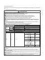
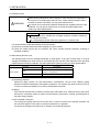
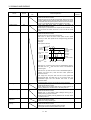
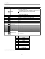
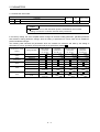
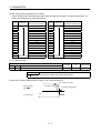
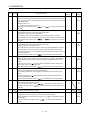
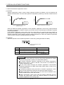
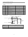
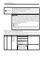
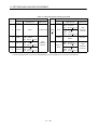
When you keep or use it, please fulfill the following environmental conditions.
Conditions
Environment
Ambient
temperature
Ambient humidity
During
operation
In storage
Servo amplifier
Servo motor
[
]
0 to 55 (non-freezing)
0 to 40 (non-freezing)
[
]
32 to 131 (non-freezing)
32 to 104 (non-freezing)
[
]
20 to 65 (non-freezing)
[
]
4 to 149 (non-freezing)
15 to 70 (non-freezing)
5 to 158 (non-freezing)
In operation
90%RH or less (non-condensing)
In storage
90%RH or less (non-condensing)
80%RH or less (non-condensing)
Ambience
Indoors (no direct sunlight) Free from corrosive gas, flammable gas, oil mist, dust and dirt
Altitude
Max. 1000m (3280 ft) above sea level
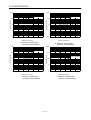
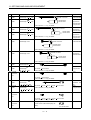
(Note)
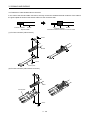
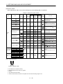
Vibration
[m/s2]
5.9 or less
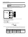
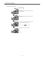
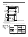
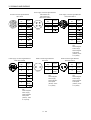
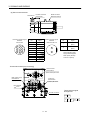
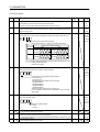
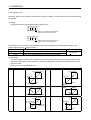
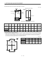
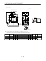
HF-MP Series
HF-KP Series
X
Y : 49
HF-SP 52 to 152
HF-SP 51 81
HC-RP Series
HC-UP 72 152
X
Y : 24.5
HF-SP 202 352
HF-SP 121 201
HC-UP 202 to 502
X : 24.5
Y : 49
HF-SP 301
HF- SP 502
X : 24.5
Y : 29.5
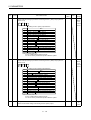
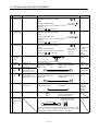
421
702
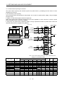
HA-LP601 to12K1
HA-LP701M to 15K1M
HA-LP502 to 22K2
HA-LP8014 12K14
HA-LP11K1M4 15K1M14
HA-LP11K24 to 22K24
HA-LP15K1 to 25K1 HA-LP22K1M
HA-LP15K14 20K14 HA-LP22K1M
X : 11.7
Y : 29.4
X
Y : 9.8
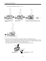
Note. Except the servo motor with reduction gear.
Securely attach the servo motor to the machine. If attach insecurely, the servo motor may come off during
operation.
The servo motor with reduction gear must be installed in the specified direction to prevent oil leakage.
Take safety measures, e.g. provide covers, to prevent accidental access to the rotating parts of the servo
motor during operation.
Never hit the servo motor or shaft, especially when coupling the servo motor to the machine. The encoder
may become faulty.
Do not subject the servo motor shaft to more than the permissible load. Otherwise, the shaft may break.
When the equipment has been stored for an extended period of time, consult Mitsubishi.
A- 3
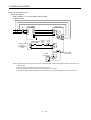
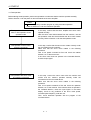
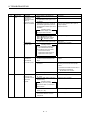
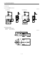
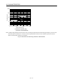
(2) Wiring
CAUTION
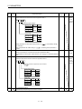
Wire the equipment correctly and securely. Otherwise, the servo motor may misoperate.
Do not install a power capacitor, surge absorber or radio noise filter (FR-BIF option) between the servo
motor and servo amplifier.
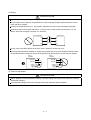
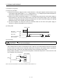
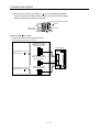
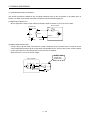
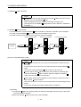
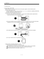
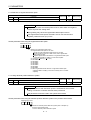
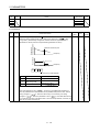
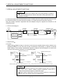
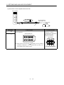
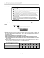
Connect the output terminals (U, V, W) correctly. Otherwise, the servo motor will operate improperly.
Connect the servo motor power terminal (U, V, W) to the servo motor power input terminal (U, V, W)
directly. Do not let a magnetic contactor, etc. intervene.
Servo Amplifier
Servo Motor
U
U
V
V
W
W
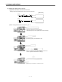
Do not connect AC power directly to the servo motor. Otherwise, a fault may occur.
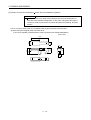
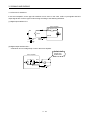
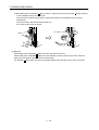
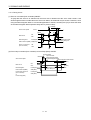
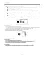
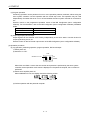
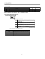
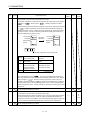
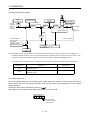
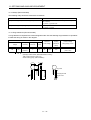
The surge absorbing diode installed on the DC output signal relay of the servo amplifier must be wired in
the specified direction. Otherwise, the forced stop (EM1) and other protective circuits may not operate.
Servo
Amplifier
Servo
Amplifier
24VDC
24VDC
DOCOM
DOCOM
DICOM
DICOM
Control
output
signal
Control
output
signal
RA
RA
(3) Test run adjustment
CAUTION
Before operation, check the parameter settings. Improper settings may cause some machines to perform
unexpected operation.
The parameter settings must not be changed excessively. Operation will be insatiable.
A- 4
(4) Usage
CAUTION
Provide an external emergency stop circuit to ensure that operation can be stopped and power switched
off immediately.
Any person who is involved in disassembly and repair should be fully competent to do the work.
Before resetting an alarm, make sure that the run signal of the servo amplifier is off to prevent an
accident. A sudden restart is made if an alarm is reset with the run signal on.
Do not modify the equipment.
Use a noise filter, etc. to minimize the influence of electromagnetic interference, which may be caused by
electronic equipment used near the servo amplifier.
Burning or breaking a servo amplifier may cause a toxic gas. Do not burn or break a servo amplifier.
Use the servo amplifier with the specified servo motor.
The electromagnetic brake on the servo motor is designed to hold the motor shaft and should not be used
for ordinary braking.
For such reasons as service life and mechanical structure (e.g. where a ballscrew and the servo motor
are coupled via a timing belt), the electromagnetic brake may not hold the motor shaft. To ensure safety,
install a stopper on the machine side.
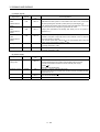
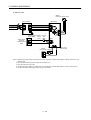
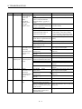
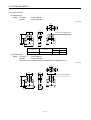
(5) Corrective actions
CAUTION
When it is assumed that a hazardous condition may take place at the occur due to a power failure or a
product fault, use a servo motor with electromagnetic brake or an external brake mechanism for the
purpose of prevention.
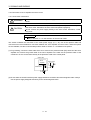
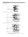
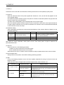
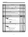
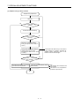
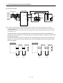
Configure the electromagnetic brake circuit so that it is activated not only by the servo amplifier signals
but also by an external forced stop (EM1).
Contacts must be open when
servo-off, when an trouble (ALM)
and when an electromagnetic brake
interlock (MBR).
Circuit must be
opened during
forced stop (EM1).
Servo motor
RA
EM1
24VDC
Electromagnetic brake
When any alarm has occurred, eliminate its cause, ensure safety, and deactivate the alarm before
restarting operation.
When power is restored after an instantaneous power failure, keep away from the machine because the
machine may be restarted suddenly (design the machine so that it is secured against hazard if restarted).
A- 5
(6) Maintenance, inspection and parts replacement
CAUTION
With age, the electrolytic capacitor of the servo amplifier will deteriorate. To prevent a secondary accident
due to a fault, it is recommended to replace the electrolytic capacitor every 10 years when used in general
environment.
Please consult our sales representative.
(7) General instruction
To illustrate details, the equipment in the diagrams of this Specifications and Instruction Manual may have
been drawn without covers and safety guards. When the equipment is operated, the covers and safety
guards must be installed as specified. Operation must be performed in accordance with this Specifications
and Instruction Manual.
A- 6
About processing of waste
When you discard servo amplifier, a battery (primary battery), and other option articles, please follow the law of
each country (area).
FOR MAXIMUM SAFETY
These products have been manufactured as a general-purpose part for general industries, and have not
been designed or manufactured to be incorporated in a device or system used in purposes related to
human life.
Before using the products for special purposes such as nuclear power, electric power, aerospace,
medicine, passenger movement vehicles or under water relays, contact Mitsubishi.
These products have been manufactured under strict quality control. However, when installing the product
where major accidents or losses could occur if the product fails, install appropriate backup or failsafe
functions in the system.
EEP-ROM life
The number of write times to the EEP-ROM, which stores parameter settings, etc., is limited to 100,000. If
the total number of the following operations exceeds 100,000, the servo amplifier and/or converter unit may
fail when the EEP-ROM reaches the end of its useful life.
Write to the EEP-ROM due to parameter setting changes
Write to the EEP-ROM due to device changes
Precautions for Choosing the Products
Mitsubishi will not be held liable for damage caused by factors found not to be the cause of Mitsubishi;
machine damage or lost profits caused by faults in the Mitsubishi products; damage, secondary damage,
accident compensation caused by special factors unpredictable by Mitsubishi; damages to products other
than Mitsubishi products; and to other duties.
A- 7
COMPLIANCE WITH EC DIRECTIVES
1. WHAT ARE EC DIRECTIVES?
The EC directives were issued to standardize the regulations of the EU countries and ensure smooth
distribution of safety-guaranteed products. In the EU countries, the machinery directive (effective in January,
1995), EMC directive (effective in January, 1996) and low voltage directive (effective in January, 1997) of the
EC directives require that products to be sold should meet their fundamental safety requirements and carry the
CE marks (CE marking). CE marking applies to machines and equipment into which servo amplifiers have
been installed.
(1) EMC directive
The EMC directive applies not to the servo units alone but to servo-incorporated machines and equipment.
This requires the EMC filters to be used with the servo-incorporated machines and equipment to comply
with the EMC directive. For specific EMC directive conforming methods, refer to the EMC Installation
Guidelines (IB(NA)67310).
(2) Low voltage directive
The low voltage directive applies also to servo units alone. Hence, they are designed to comply with the low
voltage directive.
This servo is certified by TUV, third-party assessment organization, to comply with the low voltage directive.
(3) Machine directive
Not being machines, the servo amplifiers need not comply with this directive.
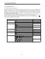
2. PRECAUTIONS FOR COMPLIANCE
(1) Servo amplifiers and servo motors used
Use the servo amplifiers and servo motors which comply with the standard model.
Servo amplifier
Servo motor
:MR-J3-10B to MR-J3-22KB
MR-J3-10B1 to MR-J3-40B1
MR-J3-11KB4 to MR-J3-22KB4
:HF-MP
HF-KP
HF-SP
HC-RP
HC-UP
HC-LP
HA-LP
HA-LP 4
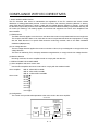
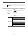
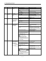
(2) Configuration
The control circuit provide safe separation to the main circuit in the servo amplifier.
Control box
Reinforced
insulating type
No-fuse
breaker
Magnetic
contactor
NFB
MC
A- 8
24VDC
power
supply
Servo
amplifier
Servo
motor
M
(3) Environment
Operate the servo amplifier at or above the contamination level 2 set forth in IEC60664-1. For this purpose,
install the servo amplifier in a control box which is protected against water, oil, carbon, dust, dirt, etc. (IP54).
(4) Power supply
(a) This servo amplifier can be supplied from star-connected supply with earthed neutral point of
overvoltage category III set forth in IEC60664-1. However, when using the neutral point of 400V system
for single phasesupply, a reinforced reinforced insulating transformer is required in the power input
section.
(b) When supplying interface power from external, use a 24VDC power supply which has been insulationreinforced in I/O.
(5) Grounding
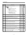
(a) To prevent an electric shock, always connect the protective earth (PE) terminals (marked
servo amplifier to the protective earth (PE) of the control box.
) of the
(b) Do not connect two ground cables to the same protective earth (PE) terminal. Always connect the
cables to the terminals one-to-one.
PE terminals
PE terminals
(c) If a leakage current breaker is used to prevent an electric shock, the protective earth (PE) terminals of the
servo amplifier must be connected to the corresponding earth terminals.
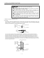
(6) Wiring
(a) The cables to be connected to the terminal block of the servo amplifier must have crimping terminals
provided with insulating tubes to prevent contact with adjacent terminals.
Crimping terminal
Insulating tube
Cable
(b) Use the servo motor side power connector which complies with the EN Standard. The EN Standard
compliant power connector sets are available from us as options. (Refer to Section 11.1)
A- 9
(7) Auxiliary equipment and options
(a) The no-fuse breaker and magnetic contactor used should be the EN or IEC standard-compliant
products of the models described in Section 11.9.
Use a type B (Note) breaker. When it is not used, provide insulation between the servo amplifier and
other device by double insulation or reinforced insulation, or install a transformer between the main
power supply and servo amplifier.
Note. Type A: AC and pulse detectable
Type B: Both AC and DC detectable
(b) The sizes of the cables described in Section 11.8 meet the following requirements. To meet the other
requirements, follow Table 5 and Appendix C in EN60204-1.
Ambient temperature: 40 (104) [°C (°F)]
Sheath: PVC (polyvinyl chloride)
Installed on wall surface or open table tray
(c) Use the EMC filter for noise reduction.
(8) Performing EMC tests
When EMC tests are run on a machine/device into which the servo amplifier has been installed, it must
conform to the electromagnetic compatibility (immunity/emission) standards after it has satisfied the
operating environment/electrical equipment specifications.
For the other EMC directive guidelines on the servo amplifier, refer to the EMC Installation
Guidelines(IB(NA)67310).
A - 10
CONFORMANCE WITH UL/C-UL STANDARD
(1) Servo amplifiers and servo motors used
Use the servo amplifiers and servo motors which comply with the standard model.
Servo amplifier
Servo motor
:MR-J3-10B to MR-J3-22KB
MR-J3-10B1 to MR-J3-40B1
MR-J3-11KB4 to MR-J3-22KB4
:HF-MP
HF-KP
HF-SP
HC-RP
HC-UP
HC-LP
HA-LP
HA-LP 4
(2) Installation
Install a fan of 100CFM (2.8m3/min) air flow 4 in (10.16 cm) above the servo amplifier or provide cooling of
at least equivalent capability.
(3) Short circuit rating
This servo amplifier conforms to the circuit whose peak current is limited to 5000A or less. Having been
subjected to the short-circuit tests of the UL in the alternating-current circuit, the servo amplifier conforms to
the above circuit.
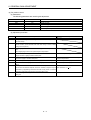
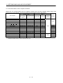
(4) Capacitor discharge time
The capacitor discharge time is as listed below. To ensure safety, do not touch the charging section for 15
minutes after power-off.
Discharge time
Servo amplifier
MR-J3-10B
MR-J3-40B
60B
[min]
20B
10B1
1
20B1
2
MR-J3-70B
3
MR-J3-40B1
4
MR-J3-100B
5
MR-J3-200B
350B
9
MR-J3-500B
700B
10
MR-J3-11KB(4)
4
MR-J3-15KB(4)
6
MR-J3-22KB(4)
8
A - 11
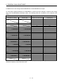
(5) Options and auxiliary equipment
Use UL/C-UL standard-compliant products.
This servo amplifier is UL/C-UL-listed when using the fuses indicated in the following table. When the servo
amplifier must comply with the UL/C-UL Standard, be sure to use these fuses.
Fuse
Servo amplifier
MR-J3-10B (1)
MR-J3-40B
Class
20B
20B1
MR-J3-60B to 100B
40B1
MR-J3-200B
MR-J3-350B
Current [A]
Voltage [V]
Servo amplifier
10
MR-J3-11KB4
15
MR-J3-15KB4
20
MR-J3-22KB4
Fuse
Class
Current [A]
Voltage [V]
100
T
150
AC600
175
40
T
70
MR-J3-500B
125
MR-J3-700B
150
MR-J3-11KB
200
MR-J3-15KB
250
MR-J3-22KB
350
AC250
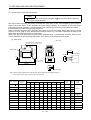
(6) Attachment of a servo motor
For the flange size of the machine side where the servo motor is installed, refer to “CONFORMANCE WITH
UL/C-UL STANDARD” in the Servo Motor Instruction Manual (Vol.2).
(7) About wiring protection
For installation in United States, branch circuit protection must be provided, in accordance with the National
Electrical Code and any applicable local codes.
For installation in Canada, branch circuit protection must be provided, in accordance with the Canada
Electrical Code and any applicable provincial codes.
<<About the manuals>>
This Instruction Manual and the MELSERVO Servo Motor Instruction Manual are required if you use the
General-Purpose AC servo MR-J3-B for the first time. Always purchase them and use the MR-J3-B safely.
Relevant manuals
Manual name
Manual No.
MELSERVO-J3 Series To Use the AC Servo Safely
IB(NA)0300077
MELSERVO Servo Motor Instruction Manual Vol.2
SH(NA)030041
EMC Installation Guidelines
IB(NA)67310
A - 12
CONTENTS
1. FUNCTIONS AND CONFIGURATION
1 - 1 to 1 -24
1.1 Introduction............................................................................................................................................... 1 - 1
1.2 Function block diagram............................................................................................................................ 1 - 2
1.3 Servo amplifier standard specifications................................................................................................... 1 - 5
1.4 Function list .............................................................................................................................................. 1 - 7
1.5 Model code definition ............................................................................................................................... 1 - 8
1.6 Combination with servo motor ................................................................................................................. 1 - 9
1.7 Structure .................................................................................................................................................. 1 -10
1.7.1 Parts identification ............................................................................................................................ 1 -10
1.7.2 Removal and reinstallation of the front cover.................................................................................. 1 -15
1.8 Configuration including auxiliary equipment .......................................................................................... 1 -18
2. INSTALLATION
2 - 1 to 2 - 6
2.1 Installation direction and clearances ....................................................................................................... 2 - 1
2.2 Keep out foreign materials....................................................................................................................... 2 - 3
2.3 Cable stress ............................................................................................................................................. 2 - 3
2.4 SSCNET cable laying............................................................................................................................ 2 - 4
2.5 Inspection Items ....................................................................................................................................... 2 - 6
2.6 Parts Having Service Lives...................................................................................................................... 2 - 6
3. SIGNALS AND WIRING
3 - 1 to 3 -46
3.1 Input power supply circuit ........................................................................................................................ 3 - 2
3.2 I/O signal Connection Example ............................................................................................................... 3 - 8
3.3 Explanation of Power Supply System .................................................................................................... 3 -10
3.3.1 Signal explanations .......................................................................................................................... 3 -10
3.3.2 Power-on sequence ......................................................................................................................... 3 -11
3.3.3 CNP1, CNP2, CNP3 wiring method ................................................................................................ 3 -12
3.4 Connectors and signal arrangements .................................................................................................... 3 -19
3.5 Signal (device) explanations................................................................................................................... 3 -20
3.6 Alarm occurrence timing chart................................................................................................................ 3 -23
3.7 Interfaces................................................................................................................................................. 3 -24
3.7.1 Internal connection diagram ............................................................................................................ 3 -24
3.7.2 Detailed description of interfaces..................................................................................................... 3 -25
3.7.3 Source I/O interfaces ....................................................................................................................... 3 -27
3.8 Instructions for the 3M connector ........................................................................................................... 3 -28
3.9 SSCNET cable connection .................................................................................................................. 3 -29
3.10 Connection of servo amplifier and servo motor ................................................................................... 3 -31
1
3.10.1 Connection instructions.................................................................................................................. 3 -31
3.10.2 Power supply cable wiring diagrams ............................................................................................. 3 -32
3.11 Servo motor with electromagnetic brake.............................................................................................. 3 -40
3.11.1 Safety precautions ......................................................................................................................... 3 -40
3.11.2 Timing charts.................................................................................................................................. 3 -41
3.11.3 Wiring diagrams (HF-MP series HF-KP series servo motor) ..................................................... 3 -43
3.12 Grounding.............................................................................................................................................. 3 -44
3.13 Control axis selection............................................................................................................................ 3 -45
4. STARTUP
4 - 1 to 4 -10
4.1 Switching power on for the first time ....................................................................................................... 4 - 1
4.1.1 Startup procedure.............................................................................................................................. 4 - 1
4.1.2 Wiring check ...................................................................................................................................... 4 - 2
4.1.3 Surrounding environment.................................................................................................................. 4 - 3
4.2 Start up ..................................................................................................................................................... 4 - 4
4.3 Servo amplifier display............................................................................................................................. 4 - 5
4.4 Test operation .......................................................................................................................................... 4 - 7
4.5 Test operation mode ................................................................................................................................ 4 - 8
4.5.1 Test operation mode in MR Configurator ......................................................................................... 4 - 8
4.5.2 Motorless operation in controller...................................................................................................... 4 -10
5. PARAMETERS
5 - 1 to 5 -26
5.1 Basic Setting Parameters (No.PA
) ................................................................................................... 5 - 1
5.1.1 Parameter list .................................................................................................................................... 5 - 1
5.1.2 Parameter write inhibit ...................................................................................................................... 5 - 2
5.1.3 Selection of regenerative brake option............................................................................................. 5 - 3
5.1.4 Using absolute position detection system ........................................................................................ 5 - 3
5.1.5 Forced stop input selection ............................................................................................................... 5 - 4
5.1.6 Auto tuning ........................................................................................................................................ 5 - 5
5.1.7 In-position range................................................................................................................................ 5 - 6
5.1.8 Selection of servo motor rotation direction....................................................................................... 5 - 7
5.1.9 Encoder output pulse ........................................................................................................................ 5 - 7
5.2 Gain/Filter Parameters (No. PB
) ....................................................................................................... 5 - 9
5.2.1 Parameter list .................................................................................................................................... 5 - 9
5.2.2 Detail list ........................................................................................................................................... 5 -10
5.3 Extension Setting Parameters (No. PC
) .......................................................................................... 5 -17
5.3.1 Parameter list ................................................................................................................................... 5 -17
5.3.2 List of details..................................................................................................................................... 5 -18
5.3.3 Analog monitor ................................................................................................................................. 5 -21
5.3.4 Alarm history clear............................................................................................................................ 5 -23
5.4 I/O Setting Parameters (No. PD
) ..................................................................................................... 5 -24
5.4.1 Parameter list ................................................................................................................................... 5 -24
5.4.2 List of details..................................................................................................................................... 5 -25
2
6. GENERAL GAIN ADJUSTMENT
6 - 1 to 6 -12
6.1 Different adjustment methods.................................................................................................................. 6 - 1
6.1.1 Adjustment on a single servo amplifier............................................................................................. 6 - 1
6.1.2 Adjustment using MR Configurator (servo configuration software)................................................. 6 - 2
6.2 Auto tuning ............................................................................................................................................... 6 - 3
6.2.1 Auto tuning mode .............................................................................................................................. 6 - 3
6.2.2 Auto tuning mode operation.............................................................................................................. 6 - 4
6.2.3 Adjustment procedure by auto tuning............................................................................................... 6 - 5
6.2.4 Response level setting in auto tuning mode .................................................................................... 6 - 6
6.3 Manual mode 1 (simple manual adjustment).......................................................................................... 6 - 7
6.4 Interpolation mode .................................................................................................................................. 6 -11
6.5 Differences in auto tuning between MELSERVO-J2 and MELSERVO-J2-Super................................ 6 -12
7. SPECIAL ADJUSTMENT FUNCTIONS
7 - 1 to 7 -16
7.1 Function block diagram............................................................................................................................ 7 - 1
7.2 Adaptive filter ......................................................................................................................................... 7 - 1
7.3 Machine resonance suppression filter..................................................................................................... 7 - 4
7.4 Advanced Vibration Suppression Control ............................................................................................... 7 - 6
7.5 Low-pass filter ......................................................................................................................................... 7 -10
7.6 Gain changing function ........................................................................................................................... 7 -10
7.6.1 Applications ...................................................................................................................................... 7 -10
7.6.2 Function block diagram.................................................................................................................... 7 -11
7.6.3 Parameters ....................................................................................................................................... 7 -12
7.6.4 Gain changing operation.................................................................................................................. 7 -14
8. TROUBLESHOOTING
8 - 1 to 8 -10
8.1 Alarms and warning list............................................................................................................................ 8 - 1
8.2 Remedies for alarms................................................................................................................................ 8 - 2
8.3 Remedies for warnings ............................................................................................................................ 8 - 8
9. OUTLINE DRAWINGS
9 - 1 to 9 -10
9.1 Servo Amplifier ......................................................................................................................................... 9 - 1
9.2 Connector................................................................................................................................................. 9 - 8
10. CHARACTERISTICS
10- 1 to 10-10
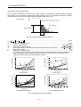
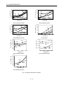
10.1 Overload protection characteristics ...................................................................................................... 10- 1
10.2 Power supply equipment capacity and generated loss ....................................................................... 10- 4
10.3 Dynamic brake characteristics.............................................................................................................. 10- 7
10.4 Cable flexing life................................................................................................................................... 10-10
10.5 Inrush currents at power-on of main circuit and control circuit...........................................................10-10
3
11. OPTIONS AND AUXILIARY EQUIPMENT
11- 1 to 11 - 74
11.1 Cable/Connector Sets........................................................................................................................... 11- 1
11.1.1 Combinations of cable/connector sets .......................................................................................... 11- 2
11.1.2 Encoder cable/connector sets ....................................................................................................... 11- 8
11.1.3 Motor power supply cables ........................................................................................................... 11-17
11.1.4 Motor brake cables........................................................................................................................ 11-18
11.1.5 SSCNET cable ........................................................................................................................... 11-19
11.2 Regenerative brake options................................................................................................................. 11-21
11.3 Brake unit ............................................................................................................................................. 11-31
11.4 Power regeneration converter ............................................................................................................. 11-33
11.5 Power regeneration common converter.............................................................................................. 11-36
11.6 External dynamic brake ....................................................................................................................... 11-43
11.7 Junction terminal block PS7DW-20V14B-F (Recommended) ........................................................... 11-47
11.8 MR Configurator................................................................................................................................... 11-49
11.9 Battery Unit MR-J3BAT ....................................................................................................................... 11-50
11.10 Heat sink outside mounting attachment (MR-J3ACN)......................................................................11-51
11.11 Recommended wires ......................................................................................................................... 11-53
11.12 No-fuse breakers, fuses, magnetic contactors ................................................................................. 11-57
11.13 Power Factor Improving DC Reactor ................................................................................................ 11-58
11.14 Power factor improving AC reactors ................................................................................................. 11-60
11.15 Relays (Recommended).................................................................................................................... 11-61
11.16 Surge absorbers (Recommended).................................................................................................... 11-61
11.17 Noise reduction techniques ............................................................................................................... 11-62
11.18 Leakage current breaker.................................................................................................................... 11-68
11.19 EMC filter (Recommended) ............................................................................................................... 11-70
12. ABSOLUTE POSITION DETECTION SYSTEM
12- 1 to 12 - 4
12.1 Features ................................................................................................................................................ 12- 1
12.2 Specifications ........................................................................................................................................ 12- 2
12.3 Battery installation procedure ............................................................................................................... 12- 3
12.4 Confirmation of absolute position detection data................................................................................. 12- 4
APPENDIX
App- 1 to App- 4
App 1. Parameter list...................................................................................................................................App- 1
App 2. Signal Layout Recording Paper ......................................................................................................App- 2
App 3. Twin type connector : Outline drawing for 721-2105/026-000 (WAGO)........................................App- 3
App 4. Combination of servo amplifier and servo motor............................................................................App- 4
4
1. FUNCTIONS AND CONFIGURATION
1. FUNCTIONS AND CONFIGURATION
1.1 Introduction
The Mitsubishi MELSERVO-J3 series general-purpose AC servo has further higher performance and higher
functions compared to the current MELSERVO-J2-Super series.
The MR-J3-B servo amplifier connects to servo system controller and others via high speed synchronous
network and operates by directly reading position data. The rotation speed/direction control of servo motor and
the high accuracy positioning are executed with the data from command module. SSCNET equipped by the
MR-J3-B servo amplifier greatly improved its communication speed and noise tolerance by adopting optical
communication system compared to the current SSCNET. For wiring distance, 50m of the maximum distance
between electrodes is also offered.
The torque limit with clamping circuit is put on the servo amplifier in order to protect the power transistor of
main circuit from the overcurrent caused by rapid acceleration/deceleration or overload. In addition, torque limit
value can be changed to desired value with parameter.
As this new series has the USB communication function, a servo configuration software-installed personal
computer or the like can be used to perform parameter setting, test operation, status display monitoring, gain
adjustment, etc.
With real-time auto tuning, you can automatically adjust the servo gains according to the machine.
The MELSERVO-J3 series servo motor is equipped with an absolute position encoder which has the resolution
of 262144 pulses/rev to ensure more accurate control as compared to the MELSERVO-J2-Super series.
Simply adding a battery to the servo amplifier makes up an absolute position detection system. This makes
home position return unnecessary at power-on or alarm occurrence by setting a home position once.
1- 1
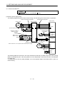
1. FUNCTIONS AND CONFIGURATION
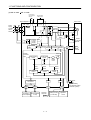
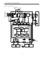
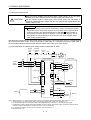
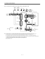
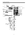
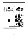
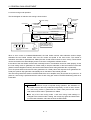
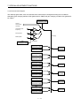
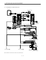
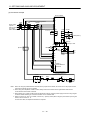
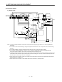
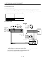
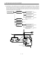
1.2 Function block diagram
The function block diagram of this servo is shown below.
(1) MR-J3-350B or less
Power factor
improving DC Regenerative
reactor
brake option
Servo amplifier P1
MC
DS
Servo motor
DN
C
(Note1)
RA
L1
Current
detector
L2
L3
CHARGE
lamp
Regenerative
TR
L21
(MR-J3-70B or more)
Control
circuit
power
supply
Regenerative
brake
U
V
V
W
W
M
Dynamic
brake
Fan
L11
U
B1
Electromagnetic
brake
B2
Base amplifier
Voltage
detection
Overcurrent
protection
Current
detection
CN2
(Note2)
Power
NFB
supply
3-phase
or 1-phase
200 to
230VAC,
or 1-phase
100 to 120V
P
P2
Encoder
Position
command
input
Model position
control
Virtual
encoder
Model speed
control
Virtual
motor
Model
position
Actual position
control
Model torque
Model
speed
Current
control
Actual speed
control
CN1A
D/A
USB
I/F Control
CN1B
Controller or Servo amplifier
Servo amplifier
or Cap
CN5
Personal
computer
USB
CN3
Analog monitor
(2 channels)
Note 1. The built-in regenerative brake resistor is not provided for the MR-J3-10B (1).
2. For 1-phase 200 to 230VAC, connect the power supply to L1,L2 and leave L3 open.
There is no L3 for 1-phase 100 to 120VAC power supply.
1- 2
Digital I/O
control
CON1
MR-J3BAT
Optional battery
(for absolute position
detection system)
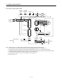
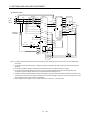
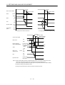
1. FUNCTIONS AND CONFIGURATION
MR-J3-700B
Power factor
improving DC
reactor
Servo amplifier P1
MC
DS
Servo motor
C N
P
P2
RA
L1
Current
detector
L2
L3
Regenerative
CHARGE
TR
U
U
V
V
W
W
M
lamp
Dynamic
brake
Fan
L11
B1
Control
circuit
power
supply
L21
Regenerative
brake
Electromagnetic
brake
B2
Base amplifier
Voltage Overcurrent Current
detection protection detection
CN2
NFB
Power
supply
3-phase
200 to
230VAC
Regenerative
brake option
Encoder
Position
command
input
Model position
control
Virtual
encoder
Model speed
control
Virtual
motor
Model
position
Actual position
control
Model
speed
Actual speed
control
Current
control
D/A
USB
I/F Control
CN1A
Model
torque
CN1B
Controller or Servo amplifier
Servo amplifier
or Cap
CN5
Personal
computer
USB
1- 3
CN3
Analog monitor
(2 channels)
Digital I/O
control
MR-J3BAT
CN4
(2) MR-J3-500B
Optional battery
(for absolute position
detection system)
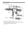
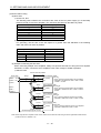
1. FUNCTIONS AND CONFIGURATION
(3) MR-J3-11KB(4) to 22KB(4)
Power factor
improving DC Regenerative
brake option
reactor
Servo amplifier P1
MC
Servo motor
N
DS
L1
Current
detector
L2
CHARGE
lamp Regene-
L3
U
U
V
V
W
W
M
rative
TR
Fan
Control
circuit
power
supply
L11
L21
B1
Electromagnetic
B2 brake
Base
amplifier
Regenerative
brake
Voltage Overcurrent
detection protection
CN2
NFB
C
Current
detection
Encoder
Position
command
input
Virtual
encoder
Model position
control
Model speed
control
Virtual
motor
Model
position
Actual position
control
Model
speed
Current
control
Model speed
control
USB
I/F Control
CN1A
Model
torque
CN5
CN1B
Controller or Servo amplifier
Servo amplifier
or Cap
D/A
Personal
computer
USB
1- 4
MR-J3BAT
CN4
Power
supply
3-phase
200 to
230VAC
or 3phase
380 to
480VAC
P
CN3
Analog monitor
(2 channels)
Digital I/O
control
Optional battery
(for absolute position
detection system)
1. FUNCTIONS AND CONFIGURATION
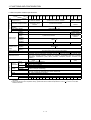
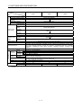
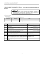
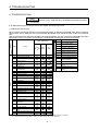
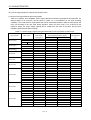
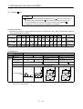
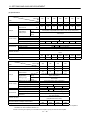
1.3 Servo amplifier standard specifications
Servo Amplifier
MR-J3- 10B 20B 40B 60B 70B 100B 200B 350B 500B 700B 11KB 15KB 22KB 10B1
20B1 40B1
Item
Power supply
Voltage/frequency
Permissible voltage fluctuation
Permissible frequency
fluctuation
Power supply capacity
Inrush current
Voltage,
frequency
Permissible
voltage
fluctuation
Control circuit
Permissible
power supply
frequency
fluctuation
Input
Inrush current
Voltage,
Interface power frequency
supply
Power supply
capacity
Control System
Dynamic brake
Protective functions
Environment
Structure
During
operation
Ambient
temperature
In storage
Ambient
humidity
In operation
In storage
[ ]
[ ]
[ ]
[ ]
3-phase or 1-phase 200
to 230VAC, 50/60Hz
3-phase or 1-phase 200
to 230VAC: 170 to
253VAC
3-phase 200 to 230VAC, 50/60Hz
1-phase 100V to
120VAC, 50/60Hz
3-phase 170 to 253VAC
1-phase 85 to
132VAC
Within 5%
Refer to Section 10.2
Refer to Section 10.5
1-phase 200 to 230VAC, 50/60Hz
1-phase 100 to
120VAC, 50/60Hz
1-phase 170 to 253VAC
1-phase 85 to
132VAC
Within 5%
30W
45W
30W
Refer to Section 10.5
DC24V 10%
(Note 1) 150mA or more
Sine-wave PWM control, current control system
Built-in
External option
Built-in
Overcurrent shut-off, regenerative overvoltage shut-off, overload shut-off (electronic thermal relay),
servo motor overheat protection, encoder error protection, regenerative brake error protection,
undervoltage, instantaneous power failure protection, overspeed protection, excessive error
protection
Self-cooled, open
Self-cooled, open
Force-cooling, open (IP00)
(IP00)
(IP00)
(Note 2) 0 to 55 (non-freezing)
32 to 131 (non-freezing)
20 to 65 (non-freezing)
4 to 149 (non-freezing)
90%RH or less (non-condensing)
Indoors (no direct sunlight)
Free from corrosive gas, flammable gas, oil mist, dust and dirt
Altitude
Max. 1000m (3280ft) above sea level
2
Vibration
5.9 [m/s ] or less
[kg] 0.8 0.8 1.0 1.0 1.4 1.4
2.3
2.3 4.6
6.2
18
18
19
0.8
0.8
1.0
Mass
[lb] 1.8 1.8 2.2 2.2 3.1 3.1 5.071 5.071 10.1 13.7 39.68 39.68 41.88 1.8
1.8
2.2
Note 1. 150mA is the value applicable when all I/O signals are used. The current capacity can be decreased by reducing the number of
I/O points.
2. When mounting the servo amplifiers closely, operate them at the ambient temperatures of 0 to 45 or at 75% or a smaller
effective load ratio.
Ambient
1- 5
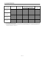
1. FUNCTIONS AND CONFIGURATION
Servo Amplifier
MR-J3-
11KB4
15KB4
22KB4
Item
3-phase 380 to 480VAC, 50/60Hz
3-phase 323 to 528VAC
Power supply
Voltage/frequency
Permissible voltage fluctuation
Permissible frequency
fluctuation
Power supply capacity
Inrush current
Voltage/frequenc
y
Permissible
voltage
fluctuation
Control circuit
Permissible
power supply
frequency
fluctuation
Input
Inrush current
Voltage,
Interface power frequency
supply
Power supply
capacity
Control System
Dynamic brake
Protective functions
Environment
Structure
During
operation
Ambient
temperature
In storage
Ambient
humidity
In operation
In storage
[ ]
[ ]
[ ]
[ ]
Within 5%
Refer to Section 10.2
Refer to Section 10.5
1-phase 380 to 480VAC, 50/60Hz
1-phase 323 to 528VAC
Within 5%
45W
Refer to Section 10.5
DC24V 10%
(Note) 150mA or more
Sine-wave PWM control, current control system
External option
Overcurrent shut-off, regenerative overvoltage shut-off, overload shut-off (electronic thermal relay),
servo motor overheat protection, encoder error protection, regenerative brake error protection,
undervoltage, instantaneous power failure protection, overspeed protection, excessive error
protection
Force-cooling, open (IP00)
(Note 2) 0 to 55 (non-freezing)
32 to 131 (non-freezing)
20 to 65 (non-freezing)
4 to 149 (non-freezing)
90%RH or less (non-condensing)
Indoors (no direct sunlight)
Free from corrosive gas, flammable gas, oil mist, dust and dirt
Altitude
Max. 1000m (3280ft) above sea level
2
Vibration
5.9 [m/s ] or less
[kg]
18
18
19
Mass
[lb]
39.68
39.68
41.88
Note. 150mA is the value applicable when all I/O signals are used. The current capacity can be decreased by reducing the number of
I/O points.
Ambient
1- 6
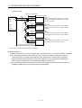
1. FUNCTIONS AND CONFIGURATION
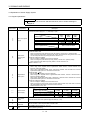
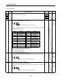
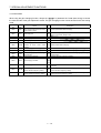
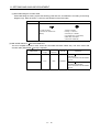
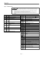
1.4 Function list
The following table lists the functions of this servo. For details of the functions, refer to the reference field.
Function
High-resolution encoder
Absolute position detection
system
Gain changing function
Advanced vibration
suppression control
Adaptive filter
Low-pass filter
Machine analyzer function
Machine simulation
Gain search function
Slight vibration suppression
control
Description
Reference
High-resolution encoder of 262144 pulses/rev is used as a servo motor
encoder.
Merely setting a home position once makes home position return
Chapter 12
unnecessary at every power-on.
You can switch between gains during rotation and gains during stop or use
Section 7.6
an external signal to change gains during operation.
This function suppresses vibration at the arm end or residual vibration.
Section 7.4
Servo amplifier detects mechanical resonance and sets filter characteristics
Section 7.2
automatically to suppress mechanical vibration.
Suppresses high-frequency resonance which occurs as servo system
Section 7.5
response is increased.
Analyzes the frequency characteristic of the mechanical system by simply
connecting a servo configuration software-installed personal computer and
servo amplifier.
MR Configurator (servo configuration software) MRZJW3-SETUP221E is
necessary for this function.
Can simulate machine motions on a personal computer screen on the basis
of the machine analyzer results.
MR Configurator (servo configuration software) MRZJW3-SETUP221E is
necessary for this function.
Personal computer changes gains automatically and searches for overshootfree gains in a short time.
MR Configurator (servo configuration software) MRZJW3-SETUP221E is
necessary for this function.
Suppresses vibration of 1 pulse produced at a servo motor stop.
Automatically adjusts the gain to optimum value if load applied to the servo
motor shaft varies. Higher in performance than MR-J2-Super series servo
amplifier.
Used when the regenerative brake option cannot provide enough
Brake until
regenerative power.
Can be used the 5kW or more servo amplifier.
Used when the regenerative brake option cannot provide enough
Return converter
regenerative power.
Can be used the 5kW or more servo amplifier.
Used when the built-in regenerative brake resistor of the servo amplifier
Regenerative brake option
does not have sufficient regenerative capability for the regenerative power
generated.
Alarm history clear
Alarm history is cleared.
Output signal (DO)
Output signal can be forced on/off independently of the servo status.
forced output
Use this function for output signal wiring check, etc.
JOG operation positioning operation
DO forced output.
Test operation mode
However, MR Configurator (servo configuration software) MRZJW3SETUP221E is necessary for positioning operation.
Analog monitor output
Servo status is output in terms of voltage in real time.
MR configurator
Using a personal computer, parameter setting, test operation, status display,
(Servo configuration software) etc. can be performed.
Auto tuning
1- 7
Parameters No. PB24
Chapter 6
Section 11.3
Section 11.4
Section 11.2
Parameter No. PC21
Section 4.5.1 (1) (d)
Section 4.5
Parameter No. PC09
Section 11.8
1. FUNCTIONS AND CONFIGURATION
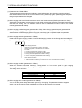
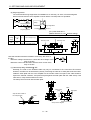
1.5 Model code definition
(1) Rating plate
AC SERVO
Model
Capacity
MR-J3-10B
POWER : 100W
INPUT : 0.9A 3PH+1PH200-230V 50Hz
3PH+1PH200-230V 60Hz
1.3A 1PH 200-230V 50/60Hz
OUTPUT: 170V 0-360Hz 1.1A
SERIAL : A34230001
Applicable power supply
Rated output current
Serial number
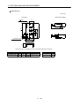
(2) Model
MR-J3-100B or less
MR
J3
MR-J3-200B 350B
B
With no regenerative resistor
Series
Symbol
-PX
Description
Indicates a servo
amplifier of 11 to 22kw
that does not use a
regenerative resistor as
standard accessory.
Power supply
Power supply
Symbol
None 3-phase or 1-phase 200
(Note 1) to 230VAC
(Note 2)
1-phase 100 to 120VAC
1
4
Rating plate
Rating plate
MR-J3-500B
MR-J3-700B
3-phase 380 to 480VAC
Note 1. 1-phase 200V to 230V is
supported by 750W or less.
2. 1-phase 100V to 120V is
supported by 400W or less.
SSCNET
compatible
Rated output
Symbol Rated
Symbol Rated
output [kW]
output [kW]
350
0.1
10
3.5
5
20
0.2
500
700
40
0.4
7
11
60
0.6
11k
70
0.75
15
15k
22k
100
1
22
200
2
Rating plate
Rating plate
MR-J3-11KB(4) or more
Rating plate
1- 8
1. FUNCTIONS AND CONFIGURATION
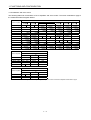
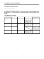
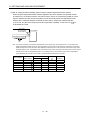
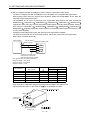
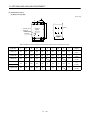
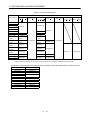
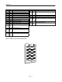
1.6 Combination with servo motor
The following table lists combinations of servo amplifiers and servo motors. The same combinations apply to
the models with electromagnetic brakes.
Servo motors
Servo amplifier
MR-J3-10B (1)
HF-MP
HF-KP
053
053
13
MR-J3-20B (1)
23
23
MR-J3-40B (1)
43
43
73
73
1000r/min
2000r/min
51
52
HC-RP
HC-UP
HC-LP
13
MR-J3-60B
MR-J3-70B
HF-SP
MR-J3-100B
81
MR-J3-200B
52
72
121
102
201
MR-J3-350B
301
MR-J3-500B
421
152
202
352
502
MR-J3-700B
102
103
153
203
353
503
152
152
202
202
352
502
302
702
MR-J3-11KB
MR-J3-15KB
MR-J3-22KB
Servo motors
Servo amplifier
HA-LP
1000r/min
1500r/min
2000r/min
601
701M
702
11K1M
11K2
15K1M
15K2
22K1M
22K2
MR-J3-500B
502
MR-J3-700B
MR-J3-11KB
MR-J3-15KB
MR-J3-22KB
801
12K1
15K1
20K1
25K1
Servo motors
HA-LP
Servo amplifier
1000r/min
MR-J3-11KB4
8014
12K14
1500r/min
2000r/min
11K1M4
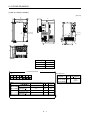
11K24
MR-J3-15KB4
15K14
15K1M4
15K24
MR-J3-22KB4
20K14
(Note) 22K1M4
22K24
Note. These servo motors may be connected depending on the production time of the servo amplifier. Please refer to app 6.
1- 9
1. FUNCTIONS AND CONFIGURATION
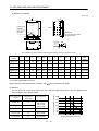
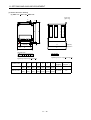
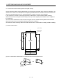
1.7 Structure
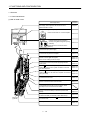
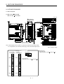
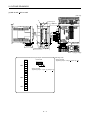
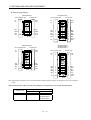
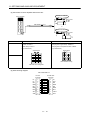
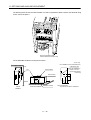
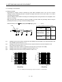
1.7.1 Parts identification
(1) MR-J3-100B or less
Name/Application
Display
The 3-digit, seven-segment LED shows the servo
status and alarm number.
Detailed
Explanation
Chapter 4
Rotary axis setting switch (SW1)
3 4 56
2
F01
F0 1
ON 4E
1
SW2
2
1
Section 3.13
B C DE
2
Used to set the axis No. of servo amplifier.
789
A
BCDE
SW1
TES
SW2
A
789
3456
SW1
2
Test operation select switch (SW2-1)
Used to perform the test operation
mode by using MR Configurator (Setup
software).
Spare (Be sure to set to the "Down"
position).
Section 3.13
Main circuit power supply connector (CNP1)
Connect the input power supply.
Section 3.1
Section 3.3
USB communication connector (CN5)
Connect with the personal computer.
Section 11.8
I/O signal connector (CN3)
Used to connect digital I/O signals.
More over an analog monitor is output
Section 3.2
Section 3.4
Control circuit connector (CNP2)
Connect the control circuit power supply/regenerative
brake option.
Section 3.1
Section 3.3
SSCNET cable connector (CN1A)
Used to connect the servo system controller or the front
axis servo amplifier.
Section 3.2
Section 3.4
SSCNET cable connector (CN1B)
Used to connect the rear axis servo amplifier. For the final Section 3.2
Section 3.4
axis, puts a cap.
Motor power supply connector (CNP3)
Connect the servo motor.
Section 3.1
Section 3.3
Encoder connector (CN2)
Used to connect the servo motor encoder.
Section 3.4
Section 11.1
Charge lamp
Lit to indicate that the main circuit is charged. While
this lamp is lit, do not reconnect the cables.
Fixed part
(2 places)
Battery connector (CN4)
Used to connect the battery for absolute position data
backup.
Section 11.9
Chapter 12
Battery holder
Contains the battery for absolute position data backup.
Section 12.3
Protective earth (PE) terminal (
Ground terminal.
Section 3.1
Section 3.3
)
Name plate
Section 1.5
1 - 10
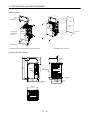
1. FUNCTIONS AND CONFIGURATION
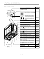
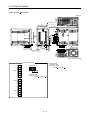
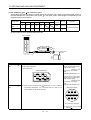
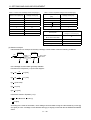
(2) MR-J3-200B MR-J3-350B
Name/Application
Display
The 3-digit, seven-segment LED shows the servo
status and alarm number.
Detailed
Explanation
Chapter 4
Rotary axis setting switch (SW1)
SW1
3456
3 4 56
2
F01
F01
ON 4E
1
2
Section 3.13
B CDE
2
A
BCDE
SW1
TES
SW2
A
789
Used to set the axis No. of servo amplifier.
789
SW2
1
2
Test operation select switch (SW2-1)
Used to perform the test operation
mode by using MR Configurator (Setup
Section 3.13
software).
Spare (Be sure to set to the "Down"
position).
Main circuit power supply connector (CNP1)
Connect the input power supply.
Section 3.1
Section 3.3
USB communication connector (CN5)
Connect with the personal computer.
Section 11.8
I/O signal connector (CN3)
Used to connect digital I/O signals.
More over an analog monitor is output
Section 3.2
Section 3.4
SSCNET cable connector (CN1A)
Used to connect the servo system controller or the front
axis servo amplifier.
Section 3.2
Section 3.4
Motor power supply connector (CNP3)
Connect the servo motor.
Section 3.1
Section 3.3
SSCNET cable connector (CN1B)
Used to connect the rear axis servo amplifier. For the final Section 3.2
Section 3.4
axis, puts a cap.
Encoder connector (CN2)
Used to connect the servo motor encoder.
Battery connector (CN4)
Used to connect the battery for absolute position data
backup.
Control circuit connector (CNP2)
Connect the control circuit power supply/regenerative
brake option.
Battery connector (CN4)
Used to connect the battery for absolute position data
backup.
Section 3.4
Section 12.3
Section 11.9
Chapter 12
Section 3.1
Section 3.3
Section 11.6
Chapter 12
Charge lamp
Lit to indicate that the main circuit is charged. While
this lamp is lit, do not reconnect the cables.
Cooling fan
Fixed part
(3 places)
Protective earth (PE) terminal (
Ground terminal.
)
Section 3.1
Section 3.3
Name plate
Section 1.5
1 - 11
1. FUNCTIONS AND CONFIGURATION
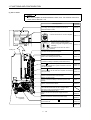
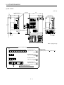
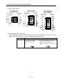
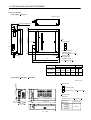
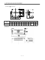
(3) MR-J3-500B
POINT
The servo amplifier is shown without the front cover. For removal of the front
cover, refer to Section 1.7.2.
Name/Application
Display
The 3-digit, seven-segment LED shows the servo
status and alarm number.
Detailed
Explanation
Chapter 4
Rotary axis setting switch (SW1)
3 4 56
2
F01
F01
ON 4E
1
Test operation select switch (SW2-1)
SW2
2
1
Cooling fan
Section 3.13
B C DE
2
Used to set the axis No. of servo amplifier.
A
BCDE
SW1
TES
SW2
A
789
3456
SW1
789
2
Used to perform the test operation
mode by using MR Configurator (Setup
Section 3.13
software).
Spare (Be sure to set to the "Down"
position).
USB communication connector (CN5)
Connect with the personal computer.
Section 11.8
I/O signal connector (CN3)
Used to connect digital I/O signals.
More over an analog monitor is output
Section 3.2
Section 3.4
Battery holder
Contains the battery for absolute position data backup.
Section 12.3
SSCNET cable connector (CN1A)
Used to connect the servo system controller or the front
axis servo amplifier.
Section 3.2
Section 3.4
SSCNET cable connector (CN1B)
Used to connect the rear axis servo amplifier. For the final Section 3.2
Section 3.4
axis, puts a cap.
Encoder connector (CN2)
Used to connect the servo motor encoder.
Section 3.4
Section 11.1
Battery connector (CN4)
Used to connect the battery for absolute position data
backup.
Section 11.9
Chapter 12
DC reactor terminal block (TE3)
Used to connect the DC reactor.
Section 3.1
Section 3.3
Charge lamp
Lit to indicate that the main circuit is charged. While
this lamp is lit, do not reconnect the cables.
Fixed part
(4 places)
Main circuit terminal block (TE1)
Used to connect the input power supply and servo
motor.
Section 3.1
Section 3.3
Control circuit terminal block (TE2)
Used to connect the control circuit power supply.
Section 3.1
Section 3.3
Protective earth (PE) terminal (
Ground terminal.
Section 3.1
Section 3.3
)
Name plate
Section 1.5
1 - 12
1. FUNCTIONS AND CONFIGURATION
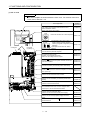
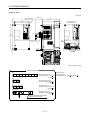
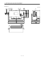
(4) MR-J3-700B
POINT
The servo amplifier is shown without the front cover. For removal of the front
cover, refer to Section 1.7.2.
Name/Application
Display
The 3-digit, seven-segment LED shows the servo
status and alarm number.
Detailed
Explanation
Chapter 4
Rotary axis setting switch (SW1)
2
F01
34 56
BCDE
F0 1
2
Used to set the axis No. of servo amplifier.
A
Cooling fan
B C DE
SW1
TES
SW2
A
789
3 4 56
SW1
789
ON 4E
1
Test operation select switch (SW2-1)
Used to perform the test operation
mode by using MR Configurator (Setup
Section 3.13
software).
SW2
2
Fixed part
(4 places)
1
Section 3.13
2
Spare (Be sure to set to the "Down"
position).
USB communication connector (CN5)
Connect with the personal computer.
Section 11.8
I/O signal connector (CN3)
Used to connect digital I/O signals.
More over an analog monitor is output
Section 3.2
Section 3.4
SSCNET cable connector (CN1A)
Used to connect the servo system controller or the front
axis servo amplifier.
Section 3.2
Section 3.4
Battery holder
Contains the battery for absolute position data backup.
Section 12.3
SSCNET cable connector (CN1B)
Used to connect the rear axis servo amplifier. For the final Section 3.2
Section 3.4
axis, puts a cap.
Encoder connector (CN2)
Used to connect the servo motor encoder.
Battery connector (CN4)
Used to connect the battery for absolute position data
backup.
DC reactor terminal block (TE3)
Used to connect the DC reactor.
Section 3.4
Section 11.1
Section 11.9
Chapter 12
Section 3.1
Section 3.3
Charge lamp
Lit to indicate that the main circuit is charged. While
this lamp is lit, do not reconnect the cables.
Control circuit terminal block (TE2)
Used to connect the control circuit power supply.
Section 3.1
Section 3.3
Main circuit terminal block (TE1)
Used to connect the input power supply and servo
motor.
Section 3.1
Section 3.3
Protective earth (PE) terminal (
Ground terminal.
Section 3.1
Section 3.3
)
Name plate
Section 1.5
1 - 13
1. FUNCTIONS AND CONFIGURATION
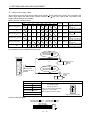
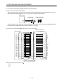
(5) MR-J3-11KB(4) or more
POINT
The servo amplifier is shown without the front cover. For removal of the front
cover, refer to Section 1.7.2.
Name/Application
Display
The 3-digit, seven-segment LED shows the servo
status and alarm number.
Detailed
Explanation
Chapter 4
Rotary axis setting switch (SW1)
F01
2
3456
2
F01
ON 4E
1
Section 3.13
BCDE
Fixed part
(4 places)
Used to set the axis No. of servo amplifier.
789
A
Cooling fan
BCDE
SW1
TEST
SW2
789
A
3456
SW
Test operation select switch (SW2-1)
SW
2
1
Used to perform the test operation mode
by using MR Configurator (Setup
Section3.13
software).
2
Spare (Be sure to set to the "Down"
position).
USB communication connector (CN5)
Connect with the personal computer.
Section 11.8
I/O signal connector (CN3)
Used to connect digital I/O signals.
More over an analog monitor is output
Section 3.2
Section 3.4
SSCNET cable connector (CN1A)
Used to connect the servo system controller or the front
axis servo amplifier.
Section 3.2
Section 3.4
Battery holder
Contains the battery for absolute position data backup.
Section 12.3
Name plate
Section 1.5
SSCNET cable connector (CN1B)
Used to connect the rear axis servo amplifier. For the final
axis, puts a cap.
Section 3.2
Section 3.4
Encoder connector (CN2)
Used to connect the servo motor encoder.
Section 3.4
Section 11.1
Battery connector (CN4)
Used to connect the battery for absolute position data
backup.
Section 11.9
Chapter 12
Charge lamp
Lit to indicate that the main circuit is charged. While
this lamp is lit, do not reconnect the cables.
Main circuit terminal block contro circuit protective
earth(TE)
Used to connect the input power supply, servo motor,
regenertive brake option and ground.
1 - 14
Section 3.1
Section 3.3
1. FUNCTIONS AND CONFIGURATION
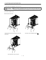
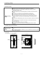
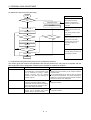
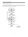
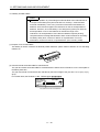
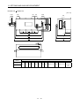
1.7.2 Removal and reinstallation of the front cover
CAUTION
Before removing or reinstalling the front cover, make sure that the charge lamp is
off more than 15 minutes after power off. Otherwise, you may get an electric shock.
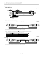
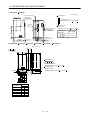
(1) For MR-J3-700B or more
Removal of the front cover
A
A
Hold the ends of lower side of the front cover with
both hands.
Pull up the cover, supporting at point
Pull out the front cover to remove.
1 - 15
A.
1. FUNCTIONS AND CONFIGURATION
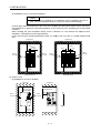
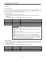
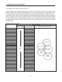
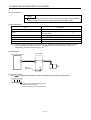
Reinstallation of the front cover
Front cover
setting tab
A
A
Insert the front cover setting tabs into the sockets of
servo amplifier (2 places).
Setting tab
Push the setting tabs until they click.
1 - 16
Pull up the cover, supporting at point
A.
1. FUNCTIONS AND CONFIGURATION
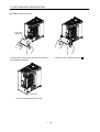
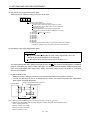
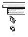
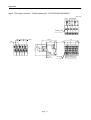
(2) For MR-J3-11KB(4) or more
Removal of the front cover
C
B
A
1) Press the removing knob on the lower side of the
front cover ( A and B ) and release the installation
hook.
2) Press the removing knob of C and release the
external hook.
3) Pull it to remove the front cover.
Reinstallation of the front cover
(Note1)
(Note1)
C
D
(Note2)
B
A
Installation hook
1) Fit the front cover installation hooks on the
sockets of body cover ( A to D ) to reinstall it.
2) Push the front cover until hearing the clicking
noise of the installation hook.
Note 1. The fan cover can be locked with enclosed screws (M4
40).
2. If drilling approximately 4 of a hole on the front cover, the front cover can be locked on the body with an enclosed screw
(M4
40).
1 - 17
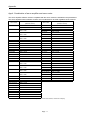
1. FUNCTIONS AND CONFIGURATION
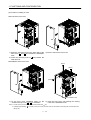
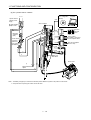
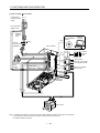
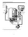
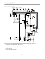
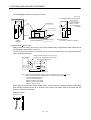
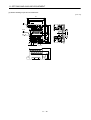
1.8 Configuration including auxiliary equipment
POINT
Equipment other than the servo amplifier and servo motor are optional or
recommended products.
(1) MR-J3-100B or less
(a) For 3-phase or 1-phase 200V to 230VAC
Personal
computer
MR Configurator
(Servo configuration
software)
RST
(Note3)
3-phase or 1-phase
200V to 230VAC
power supply
CN5
Servo amplifier
No-fuse breaker
(NFB) or fuse
Junction terminal
block
CN3
Magnetic
contactor
(MC)
CN1A
(Note2)
Line noise
filter
(FR-BLF01)
CN1B
U
Servo system
controller or Front axis
servo amplifier CN1B
Rear servo amplifier
CN1A or Cap
V W
CN2
CN4
L1
L2
L3
(Note2)
Power factor
improving DC
reactor
(FR-BEL)
(Note1)
Battery unit
MR-J3BAT
P1
Servo motor
P2
P
Regenerative brake
option
C
L11
L21
Note 1. The battery unit(option) is used for the absolute position detection system in the position control mode.
2. The AC reactor can also be used. In this case, the DC reactor cannot be used.
3. A 1-phase 200V to 230VAC power supply may be used with the servo amplifier of MR-J3-70B or less.
For 1-phase 200V to 230VAC, connect the power supply to L1
L2 and leave L3 open.
1 - 18
1. FUNCTIONS AND CONFIGURATION
(b) For 1-phase 100V to 120VAC
MR Configurator
(Servo configuration
software)
R S
1-phase 100V to
120VAC power
supply
Personal
computer
CN5
Servo amplifier
No-fuse breaker
(NFB) or fuse
CN3
Magnetic
contactor
(MC)
Junction
terminal
block
(Note2)
Power factor
improving
(FR-BAL)
Line noise filter
(FR-BSF01)
CN1A
Servo system
controller or Front axis
servo amplifier CN1B
CN1B
Rear servo amplifier
CN1A or Cap
U
VW
CN2
CN4
L1
(Note1)
Battery unit
MR-J3BAT
L2
Servo motor
P
C
Regenerative brake
option
L11
L21
Note 1. The battery unit(option) is used for the absolute position detection system in the position control mode.
2. The power factor improving DC reactor cannot be used.
1 - 19
1. FUNCTIONS AND CONFIGURATION
(2) MR-J3-200B MR-J3-350B
RST
3-phase 200V
to 230VAC power
supply
No-fuse breaker
(NFB) or fuse
Magnetic
contactor
(MC)
MR Configurator
(Servo configuration
software)
CN5
(Note2)
(Note3)
Line noise filter
(FR-BSF01)
Personal
computer
Servo amplifier
L1
L2
L3
CN3
Junction
terminal
block
P1
P2
(Note2)
Power factor
improving DC
reactor
(FR-BEL)
L11
Regenerative P
brake option C
L21
CN1A
Servo system
controller or Front axis
servo amplifier CN1B
CN1B
Rear servo amplifier
CN1A or Cap
CN2
CN4
(Note1)
Battery unit
MR-J3BAT
UV
W
Servo motor
Note 1. The battery unit(option) is used for the absolute position detection system in the position control mode.
2. The AC reactor can also be used. In this case, the DC reactor cannot be used.
3. For MR-J3-350B, use FR-BLF.
1 - 20
1. FUNCTIONS AND CONFIGURATION
(3) MR-J3-500B
3-phase 200V
to 230VAC power
supply
RST
CN5
No-fuse breaker
(NFB) or fuse
MR Configurator
(Servo configuration
software)
Personal
computer
Servo amplifier
Junction
terminal
block
CN3
Magnetic
contactor
(MC)
(Note2)
(Note1)
Battery unit
MR-J3BAT
Servo system
controller or Front axis
servo amplifier CN1B
CN1A
Line noise filter
(FR-BLF)
Rear servo amplifier
CN1A or Cap
CN1B
CN2
CN4
L11 L21
P1
P2
L3
(Note2)
Power factor
improving DC
reactor
(FR-BEL)
L2
L1
P C
U V W
Regenerative brake
option
Servo motor
Note 1. The battery unit(option) is used for the absolute position detection system in the position control mode.
2. The AC reactor can also be used. In this case, the DC reactor cannot be used.
1 - 21
1. FUNCTIONS AND CONFIGURATION
(4) MR-J3-700B
RST
Personal
computer
MR Configurator
(Servo configuration
software)
3-phase 200V
to 230VAC power
supply
CN5
No-fuse breaker
(NFB) or fuse
Servo amplifier
Magnetic
contactor
(MC)
Junction
terminal
block
CN3
(Note1) Battery unit
MR-J3BAT
(Note2)
Line noise filter
(FR-BLF)
L11 L21
(Note2)
Power factor
improving DC
reactor
(FR-BEL)
CN1A
Servo system
controller or Front axis
servo amplifier CN1B
CN1B
Rear servo amplifier
CN1A or Cap
CN2
CN4
P2
P1
L3
L2
L1
P C
U V W
Regenerative
brake
Servo motor
Note 1. The battery unit(option) is used for the absolute position detection system in the position control mode.
2. The AC reactor can also be used. In this case, the DC reactor cannot be used.
1 - 22
1. FUNCTIONS AND CONFIGURATION
(5) MR-J3-11KB(4) or more
3-phase 200V
to 230VAC
power
supply or 3phase 380V to
480VAC
RST
CN5
No-fuse
breaker (NFB)
or fuse
MR Configurator
(Servo cinfiguration
software )
Personal
computer
L21
Servo amplifier
L11
Magnetic
contactor
(MC)
Junction
terminal
block
CN3
(Note2)
(Note1)
Battery unit
MR-J3BAT
Line noise filter
(FR-BLF)
Servo system
controller or Front axis
servo amplifier CN1B
CN1A
CN1B
Rear servo smplifier
CN1A or Cap
CN2
CN4
L3
L2
L1
(Note2)
Power factor improving
DC reactor (FR-BEL)
W V U
P1
P
P
C
Regenerative
brake
Servo motor
Note 1. The battery unit(option) is used for the absolute position detection system in the position control mode.
2. The AC reactor can also be used. In this case, the DC reactor cannot be used.
1 - 23
1. FUNCTIONS AND CONFIGURATION
MEMO
1 - 24
2. INSTALLATION
2. INSTALLATION
CAUTION
Stacking in excess of the limited number of products is not allowed.
Install the equipment to incombustibles. Installing them directly or close to
combustibles will led to a fire.
Install the equipment in a load-bearing place in accordance with this Instruction
Manual.
Do not get on or put heavy load on the equipment to prevent injury.
Use the equipment within the specified environmental condition range.
Provide an adequate protection to prevent screws, metallic detritus and other
conductive matter or oil and other combustible matter from entering the servo
amplifier.
Do not block the intake/exhaust ports of the servo amplifier. Otherwise, a fault may
occur.
Do not subject the servo amplifier to drop impact or shock loads as they are
precision equipment.
Do not install or operate a faulty servo amplifier.
When the product has been stored for an extended period of time, consult
Mitsubishi.
2.1 Installation direction and clearances
CAUTION
The equipment must be installed in the specified direction. Otherwise, a fault may
occur.
Leave specified clearances between the servo amplifier and control box inside
walls or other equipment.
(1) 7kW or less
(a) Installation of one servo amplifier
Control box
Control box
40mm
or more
Wiring allowance
80mm
Servo amplifier
10mm
or more
Top
10mm
or more
Bottom
40mm
or more
2- 1
2. INSTALLATION
(b) Installation of two or more servo amplifiers
POINT
Mounting closely is available for a combination of servo amplifiers of 3.5kw or
less. The servo amplifiers of 5kw or more can not be mounted closely.
Leave a large clearance between the top of the servo amplifier and the internal surface of the control box,
and install a fan to prevent the internal temperature of the control box from exceeding the environmental
conditions.
When installing the servo amplifiers closely, leave a clearance of 1mm between the adjacent servo
amplifiers in consideration of mounting tolerances.
In this case, bring the ambient temperature within 0 to 45 , or use it at 75% or a smaller effective load
ratio.
Control box
Control box
100mm
or more
10mm
or more
100mm
or more
1mm
30mm
or more
30mm
or more
1mm
30mm
or more
30mm
or more
40mm
or more
40mm or more
Leaving clearance
Mounting closely
(2) 11kW or more
(a) Installation of one servo amplifier
Control box
Control box
40mm or more
Servo amplifier
Wiring allowance
Top
80mm
10mm
or more
10mm
or more
Bottom
120mm
or more
2- 2
2. INSTALLATION
(b) Installation of two or more servo amplifiers
Leave a large clearance between the top of the servo amplifier and the internal surface of the control
box, and install a fan to prevent the internal temperature of the control box from exceeding the
environmental conditions.
Control box
100mm
or more
10mm or more
30m
or more
30mm
or more
120mm or more
(3) Others
When using heat generating equipment such as the regenerative brake option, install them with full
consideration of heat generation so that the servo amplifier is not affected.
Install the servo amplifier on a perpendicular wall in the correct vertical direction.
2.2 Keep out foreign materials
(1) When installing the unit in a control box, prevent drill chips and wire fragments from entering the servo
amplifier.
(2) Prevent oil, water, metallic dust, etc. from entering the servo amplifier through openings in the control box or
a fan installed on the ceiling.
(3) When installing the control box in a place where there are much toxic gas, dirt and dust, conduct an air
purge (force clean air into the control box from outside to make the internal pressure higher than the
external pressure) to prevent such materials from entering the control box.
2.3 Cable stress
(1) The way of clamping the cable must be fully examined so that flexing stress and cable's own weight stress
are not applied to the cable connection.
(2) For use in any application where the servo motor moves, fix the cables (encoder, power supply, brake)
supplied with the servo motor, and flex the optional encoder cable or the power supply and brake wiring
cables. Use the optional encoder cable within the flexing life range. Use the power supply and brake wiring
cables within the flexing life of the cables.
(3) Avoid any probability that the cable sheath might be cut by sharp chips, rubbed by a machine corner or
stamped by workers or vehicles.
(4) For installation on a machine where the servo motor will move, the flexing radius should be made as large
as possible. Refer to section 10.4 for the flexing life.
2- 3
2. INSTALLATION
2.4 SSCNET
cable laying
SSCNET cable is made from optical fiber. If optical fiber is added a power such as a major shock, lateral
pressure, haul, sudden bending or twist, its inside distorts or breaks, and optical transmission will not be
available. Especially, as optical fiber for MR-J3BUS M MR-J3BUS M-A is made of synthetic resin, it
melts down if being left near the fire or high temperature. Therefore, do not make it touched the part, which
becomes high temperature, such as radiator or regenerative brake option of servo amplifier.
Read described item of this section carefully and handle it with caution.
(1) Minimum bend radius
Make sure to lay the cable with greater radius than the minimum bend radius. Do not press the cable to
edges of equipment or others. For SSCNET cable, the appropriate length should be selected with due
consideration for the dimensions and arrangement of servo amplifier. When closing the door of control box,
pay careful attention for avoiding the case that SSCNET cable is hold down by the door and the cable
bend becomes smaller than the minimum bend radius.
For the minimum bend radius, refer to Section 11.1.5.
(2) Bundle fixing
Fix the cable at the closest part to the connector with bundle material in order to prevent SSCNET cable
from putting its own weight on CN1A CN1B connector of servo amplifier. Optical cord should be given
loose slack to avoid from becoming smaller than the minimum bend radius, and it should not be twisted.
Connector
Optical cord
Loose slack
Cable
Bundle material
Recommended product:
NK clamp SP type
( NIX, INC.)
When laying cable, fix and hold it in position with using cushioning such as sponge or rubber which does
not contain plasticizing material.
Never use vinyl tape for cord. Plasticizing material in vinyl tape goes into optical fiber and lowers the optical
characteristic. At worst, it may cause wire breakage. If using adhesive tape for cable laying, the fire
resistant acetate cloth adhesive tape 570F (Teraoka Seisakusho Co., Ltd) is recommended.
If laying with other wires, do not make the cable touched wires or cables made from soft polyvinyl chloride
(PVC), polyethylene resin (PE), teflon (Fluorocarbon resin) or nylon which contains plasticizing material.
(3) Tension
If tension is added on optical cable, the increase of transmission loss occurs because of external force
which concentrates on the fixing part of optical fiber or the connecting part of optical connector. At worst,
the breakage of optical fiber or damage of optical connector may occur. For cable laying, handle without
putting forced tension. For the tension strength, refer to Section 11.1.5.
2- 4
2. INSTALLATION
(4) Lateral pressure
If lateral pressure is added on optical cable, the optical cable itself distorts, internal optical fiber gets
stressed, and then transmission loss will increase. At worst, the breakage of optical cable may occur. As
the same condition also occurs at cable laying, do not tighten up optical cable with a thing such as nylon
band (TY-RAP).
Do not trample it down or tuck it down with the door of control box or others.
(5) Twisting
If optical fiber is twisted, it will become the same stress added condition as when local lateral pressure or
bend is added. Consequently, transmission loss increases, and the breakage of optical fiber may occur at
worst.
(6) Disposal
When incinerating optical cable (cord) used for SSCNET , hydrogen fluoride gas or hydrogen chloride gas
which is corrosive and harmful may be generated. For disposal of optical fiber, request for specialized
industrial waste disposal services who has incineration facility for disposing hydrogen fluoride gas or
hydrogen chloride gas.
2- 5
2. INSTALLATION
2.5 Inspection Items
WARNING
Before starting maintenance and/or inspection, make sure that the charge lamp is
off more than 15 minutes after power-off. Then, confirm that the voltage is safe in
the tester or the like. Otherwise, you may get an electric shock.
Any person who is involved in inspection should be fully competent to do the work.
Otherwise, you may get an electric shock. For repair and parts replacement,
contact your safes representative.
POINT
Do not test the servo amplifier with a megger (measure insulation resistance),
or it may become faulty.
Do not disassemble and/or repair the equipment on customer side.
It is recommended to make the following checks periodically:
(a) Check for loose terminal block screws. Retighten any loose screws.
(b) Check the cables and the like for scratches and cracks. Perform periodic inspection according to
operating conditions.
2.6 Parts Having Service Lives
The following parts must be changed periodically as listed below. If any part is found faulty, it must be
changed immediately even when it has not yet reached the end of its life, which depends on the operating
method and environmental conditions. For parts replacement, please contact your sales representative.
Part name
Life guideline
Smoothing capacitor
Servo amplifier
Relay
Cooling fan
Absolute position battery
10 years
Number of power-on and number of emergency
stop times : 100,000 times
10,000 to 30,000hours (2 to 3 years)
Refer to Section 12.2
(a) Smoothing capacitor
Affected by ripple currents, etc. and deteriorates in characteristic. The life of the capacitor greatly
depends on ambient temperature and operating conditions. The capacitor will reach the end of its life in
10 years of continuous operation in normal air-conditioned environment.
(b) Relays
Their contacts will wear due to switching currents and contact faults occur. Relays reach the end of their
life when the cumulative number of power-on and emergency stop times is 100,000, which depends on
the power supply capacity.
(c) Servo amplifier cooling fan
The cooling fan bearings reach the end of their life in 10,000 to 30,000 hours. Normally, therefore, the
fan must be changed in a few years of continuous operation as a guideline.
It must also be changed if unusual noise or vibration is found during inspection.
2- 6
3. SIGNALS AND WIRING
3. SIGNALS AND WIRING
WARNING
Any person who is involved in wiring should be fully competent to do the work.
Before starting wiring, switch power off, then wait for more than 15 minutes, and
after the charge lamp has gone off, make sure that the voltage is safe in the tester
or like. Otherwise, you may get an electric shock.
Ground the servo amplifier and the servo motor securely.
Do not attempt to wire the servo amplifier and servo motor until they have been
installed. Otherwise, you may get an electric shock.
The cables should not be damaged, stressed excessively, loaded heavily, or
pinched. Otherwise, you may get an electric shock.
Wire the equipment correctly and securely. Otherwise, the servo motor may
misoperate, resulting in injury.
Connect cables to correct terminals to prevent a burst, fault, etc.
Ensure that polarity ( , ) is correct. Otherwise, a burst, damage, etc. may occur.
The surge absorbing diode installed to the DC relay designed for control output
should be fitted in the specified direction. Otherwise, the signal is not output due to
a fault, disabling the forced stop (EM1) and other protective circuits.
Servo amplifier
Servo Amplifier
24VDC
24VDC
DOCOM
DOCOM
DICOM
DICOM
CAUTION
Control output
signal
RA
Control output
signal
RA
Use a noise filter, etc. to minimize the influence of electromagnetic interference,
which may be given to electronic equipment used near the servo amplifier.
Do not install a power capacitor, surge suppressor or radio noise filter (FR-BIF
option) with the power line of the servo motor.
When using the regenerative brake resistor, switch power off with the alarm signal.
Otherwise, a transistor fault or the like may overheat the regenerative brake
resistor, causing a fire.
Do not modify the equipment.
3- 1
3. SIGNALS AND WIRING
3.1 Input power supply circuit
CAUTION
When the servo amplifier has become faulty, switch power off on the servo
amplifier power side. Continuous flow of a large current may cause a fire.
Use the trouble signal to switch main circuit power supply off. Otherwise, a
regenerative brake transistor fault or the like may overheat the regenerative brake
resistor, causing a fire.
POINT
Even if alarm has occurred, do not switch off the control circuit power supply.
When the control circuit power supply has been switched off, optical module
does not operate, and optical transmission of SSCNET communication is
interrupted. Therefore, the servo amplifier on the rear axis displays "AA" at
the indicator and turns into base circuit shut-off. The servo amplifier stops
with starting dynamic brake.
Wire the power supply/main circuit as shown below so that power is shut off and the servo-on command turned
off as soon as an alarm occurs, a servo forced stop is made valid, or a controller forced stop is made valid. A
no-fuse breaker (NFB) must be used with the input cables of the main circuit power supply.
(1) For 3-phase 200V to 230VAC power supply to MR-J3-10B to MR-J3-350B
(Note4)
Alarm
RA1
Controller
forced stop
RA2
Forced
stop
ON
OFF
MC
MC
SK
NFB
MC
3-phase
200 to
230VAC
(Note 1)
Servo amplifier
CNP1
L1
CNP3
L2
U
Servo motor
(Note 6)
U
2
L3
V
V
3
N
W
W
4
M
1
P1
P2
Motor
PE
CNP2
P
(Note 2)
C
D
CN2
L11
(Note 3)
Encoder cable
Encoder
L21
Forced stop
(Note 5)
CN3
CN3
EM1
DOCOM
DOCOM
DICOM
ALM
24VDC
RA1
Trouble
(Note 4)
(Note 5)
Note 1. Always connect P1-P2. (Factory-wired.) When using the power factor improving DC reactor, refer to Section 11.13.
2. Always connect P-D. (Factory-wired.) When using the regenerative brake option, refer to Section 11.2.
3. For the encoder cable, use of the option cable is recommended. Refer to Section 11.1 for selection of the cable.
4. If deactivating output of trouble (ALM) with parameter change, configure up the power supply circuit which switches off the
magnetic contactor after detection of alarm occurrence on the controller side.
5. For the sink I/O interface. For the source I/O interface, refer to Section 3.7.3.
6. Refer to Section 3.10.
3- 2
3. SIGNALS AND WIRING
(2) For 1-phase 200V to 230VAC power supply to MR-J3-10B to MR-J3-70B
(Note4)
Alarm
RA1
Controller
forced stop
RA2
Forced
stop
ON
OFF
MC
MC
SK
NFB
MC
1-phase
200V to
230VAC
(Note 1)
Servo amplifier
CNP1
L1
CNP3
L2
U
Servo motor
(Note 6)
U
2
L3
V
V
3
N
W
W
4
M
1
P1
P2
Motor
PE
CNP2
P
(Note 2)
C
D
CN2
L11
(Note 3)
Encoder cable
Encoder
L21
Forced stop
(Note 5)
CN3
CN3
EM1
DOCOM
DOCOM
DICOM
ALM
24VDC
RA1
Trouble
(Note 4)
(Note 5)
Note 1. Always connect P1-P2. (Factory-wired.) When using the power factor improving DC reactor, refer to Section 11.13.
2. Always connect P-D. (Factory-wired.) When using the regenerative brake option, refer to Section 11.2.
3. For the encoder cable, use of the option cable is recommended. Refer to Section 11.1 for selection of the cable.
4. If deactivating output of trouble (ALM) with parameter change, configure up the power supply circuit which switches off the
magnetic contactor after detection of alarm occurrence on the controller side.
5. For the sink I/O interface. For the source I/O interface, refer to Section 3.7.3.
6. Refer to Section 3.10.
3- 3
3. SIGNALS AND WIRING
(3) For MR-J3-10B1 to MR-J3-40B1
(Note4)
Alarm
RA1
Controller
forced stop
RA2
Forced
stop
ON
OFF
MC
MC
SK
NFB
MC
1-phase
100 to
120VAC
(Note 1)
Servo amplifier
CNP1
L1
CNP3
Blank
U
Servo motor
(Note 6)
U
2
L2
V
V
3
N
W
W
4
M
1
P1
P2
Motor
PE
CNP2
P
(Note 2)
C
D
CN2
L11
(Note 3)
Encoder cable
Encoder
L21
Forced stop
(Note 5)
CN3
CN3
EM1
DOCOM
DOCOM
DICOM
ALM
24VDC
RA1
Trouble
(Note 4)
(Note 5)
Note 1. Always connect P1-P2. (Factory-wired.) The power factor improving DC reactor cannot be used.
2. Always connect P-D. (Factory-wired.) When using the regenerative brake option, refer to Section 11.2.
3. For the encoder cable, use of the option cable is recommended. Refer to Section 11.1 for selection of the cable.
4. If deactivating output of trouble (ALM) with parameter change, configure up the power supply circuit which switches off the
magnetic contactor after detection of alarm occurrence on the controller side.
5. For the sink I/O interface. For the source I/O interface, refer to Section 3.7.3.
6. Refer to Section 3.10.
3- 4
3. SIGNALS AND WIRING
(4) MR-J3-500B MR-J3-700B
(Note4)
Alarm
RA1
Controller
forced stop
RA2
Forced
stop
ON
OFF
MC
MC
SK
Servo amplifier
NFB
MC
3-phase
200 to
230VAC
TE1
L1
Built-in
L2 regenerative U
L3 brake resistor V
(Note 2)
P
Servo motor
(Note 6)
W
U
2
V
3
W
4
Motor
M
1
C
TE2
L11
PE
L21
TE3
N
(Note 1)
CN2
P1
(Note 3)
Encoder cable
Encoder
P2
(Note 5)
Forced stop
CN3
CN3
EMG
DOC
DOCOM
DICO
ALM
24VDC
RA1
Trouble
(Note 4)
(Note 5)
Note 1. Always connect P1-P2. (Factory-wired.) When using the power factor improving DC reactor, refer to Section 11.13.
2. When using the regenerative brake option, refer to Section 11.2.
3. For the encoder cable, use of the option cable is recommended. Refer to Section 11.1 for selection of the cable.
4. If deactivating output of trouble (ALM) with parameter change, configure up the power supply circuit which switches off the
magnetic contactor after detection of alarm occurrence on the controller side.
5. For the sink I/O interface. For the source I/O interface, refer to Section 3.7.3.
6. Refer to Section 3.10.
3- 5
3. SIGNALS AND WIRING
(5) MR-J3-11KB to MR-J3-22KB
Servo motor
thermal relay
RA3
(Note4)
Alarm
RA1
Controller
forced stop
RA2
Forced
stop
OFF
ON
MC
MC
SK
Servo amplifier
NFB
MC
3-phase 200
to 230VAC
L2
U
L3
V
C
W
(Note 2)
P
Regenerative
brake resistor
P1
Servo motor
Dynamic
break
TE
L1
U
V
M
W
(Note 6)
(Note 1)
PE
L11
L21
CN2
(Note3)
Encoder cable
Encoder
BU
BV (Note 7)
Fan
OHS1
24VDC
power supply
+
BW
OHS2
Servo motor
thermal relay
RA3
-
(Note 5)
Forced stop
CN3
CN3
EM1
DOCOM
DOCOM
DICOM
ALM
24VDC
RA1
Trouble
(Note 4)
(Note 5)
Note 1. Always connect P-P1. (Factory-wired.) When using the power factor improving DC reactor, refer to Section 11.13.
2. When using the regenerative brake option, refer to Section 11.2.
3. For the encoder cable, use of the option cable is recommended. Refer to Section 11.1 for selection of the cable.
4. If deactivating output of trouble (ALM) with parameter change, configure up the power supply circuit which switches off the
magnetic contactor after detection of alarm occurrence on the controller side.
5. For the sink I/O interface. For the source I/O interface, refer to Section 3.7.3.
6. Refer to Section 3.10.
7. There is no BW if HA-LP11K2 is used.
3- 6
3. SIGNALS AND WIRING
(6) MR-J3-11KB4 to MR-J3-22KB4
Servo motor (Note4)
thermal relay Alarm
RA1
RA3
Controller
forced stop
RA2
Forced
stop
OFF
ON
MC
(Note 8)
Cooling fan
power supply
MC
SK
Stepdown
transformer
NFB
Servo amplifier
MC
3-phase
380V to
480VAC
L2
U
L3
V
C
P
Regenerative
brake resistor
Servo motor
Dynamic
break
TE
L1
U
V
M
W
W
(Note 6)
(Note 2)
(Note 1)
P1
PE
L11
L21
CN2
(Note3)
Encoder cable
Encoder
BU
BV
Fan
OHS1
24VDC
power supply
(Note 7)
BW
OHS2
Servo motor
thermal relay
RA3
(Note 5)
Forced stop
CN3
CN3
EM1
DOCOM
DOCOM
DICOM
ALM
24VDC
RA1
Trouble
(Note 4)
(Note 5)
Note 1. Always connect P-P1. (Factory-wired.) When using the power factor improving DC reactor, refer to Section 11.13.
2. When using the regenerative brake option, refer to Section 11.2.
3. For the encoder cable, use of the option cable is recommended. Refer to Section 11.1 for selection of the cable.
4. If deactivating output of trouble (ALM) with parameter change, configure up the power supply circuit which switches off the
magnetic contactor after detection of alarm occurrence on the controller side.
5. For the sink I/O interface. For the source I/O interface, refer to Section 3.7.3.
6. Refer to Section 3.10.
7. There is no BW if HA-LP11K24 is used.
8. For the cooling fan power supply, refer to (3) (b) in Section 3.10.2.
3- 7
3. SIGNALS AND WIRING
3.2 I/O signal Connection Example
Servo amplifier
(Note10)
24VDC
(Note12) (Note12)
CN3
5
DOCOM
3
(Note3,4)Forced stop
EM1 20
2
DI1
(Note15)
DI2 12
(Note5)
DI3 19
MR Configurator
Personal
USB cable
(Servo Configuration computer MR-J3USBCBL3M
software)
(option)
(Note14)
Power
supply
DICOM
CN5
Servo system
controller (Note6)
SSCNET cable
(option)
CN1A
CN3
13 MBR
INP
RA2
Impogetion
15
ALM
RA3
Trouble (Note11)
10
DICOM
(Note13,14)
6
LA
16 LAR
7
LB
17 LBR
8
LZ
18 LZR
11 LG
4 MO1
1
LG
14 MO2
Plate
SD
SW1
CN1B
12
(Note1)
Between electrodes
MR-J3-B (Note7)
(2 axis)
SW1
CN1A
SW2 (Note8)
12
(Note6)
SSCNET
(option)
MR-J3-B (Note7)
(3 axis)
SW1
CN1A
cable
CN1B
SW2 (Note8)
12
MR-J3-B (Note7)
(n axis)
SW1
CN1A
(Note9)
Cap
CN1B
(Note2)
Magnetic brake interlock
9
SW2 (Note8)
CN1B
RA1
SW2 (Note8)
12
3- 8
Encoder A-phase pulse
(differential line driver)
Encoder B-phase pulse
(differential line driver)
Encoder Z-phase pulse
(differential line driver)
Control common
Analog monitor 1
Max. 1mA meter
10k
both directions
A
Analog monitor 2
10k
Max. 1mA meter
both directions
2m Max
A
3. SIGNALS AND WIRING
Note 1 To prevent an electric shock, always connect the protective earth (PE) terminal (terminal marked ) of the servo amplifier to the
protective earth (PE) of the control box.
2. Connect the diode in the correct direction. If it is connected reversely, the servo amplifier will be faulty and will not output
signals, disabling the forced stop (EM1) and other protective circuits.
3. If the controller does not have an forced stop (EM1) function, always install a forced stop switch (Normally closed).
4. When starting operation, always turn on the forced stop (EM1). (Normally closed contacts) By setting " 1
" in DRU
parameter No.PA04 of the drive unit, the forced stop (EM1) can be made invalid.
5. Use MRZJW3-SETUP 221E.
6. For the distance between electrodes of SSCNET cable, refer to the following table.
Cable
Standard code inside panel
Cable model name
MR-J3BUS
Cable length
M
0.15m to 3m
Standard cable outside panel
MR-J3BUS
M-A
5m to 20m
Long-distance cable
MR-J3BUS
M-B
30m to 50m
Distance between
electrodes
20m
50m
7. The wiring of the second and subsequent axes is omitted.
8. Up to eight axes (n 1 to 8) may be connected. Refer to Section 3.13 for setting of axis selection.
9. Make sure to put a cap on the unused CN1A CN1B.
10. Supply 24VDC 10% 150mA current for interfaces from the outside. 150mA is the value applicable when all I/O signals are
used. The current capacity can be decreased by reducing the number of I/O points. Refer to Section 3.7.2 (1) that gives the
current value necessary for the interface.
11. Trouble (ALM) turns on in normal alarm-free condition. When this signal is switched off (at occurrence of an alarm), the output
of the programmable controller should be stopped by the sequence program.
12. The pins with the same signal name are connected in the servo amplifier.
13. The signal can be changed by parameter No.PD07, PD08, PD09.
14. For the sink I/O interface. For the source I/O interface, refer to Section 3.7.3.
15.Devices can be assigned for DI1 DI2 DI3 with controller setting. For devices that can be assigned, refer to the controller
instruction manual. The following devices can be assigned for Q172HCPU Q173HCPU QD75MH.
DI1: upper stroke limit (FLS)
DI2: lower stroke limit (RLS)
DI3: Proximity dog (DOG)
3- 9
3. SIGNALS AND WIRING
3.3 Explanation of Power Supply System
3.3.1 Signal explanations
POINT
For the layout of connector and terminal block, refer to outline drawings in
Chapter 9.
Abbreviation
Connection Target
(Application)
Description
Supply the following power to L1, L2, L3. For the 1-phase 200V to 230VAC power supply,
connect the power supply to L1, L2, and keep L3 open.
Servo amplifier
L1
L2
L3
Main circuit power
supply
Power supply
3-phase 200V to 230VAC, 50/60Hz
1-phase 200V to 230VAC, 50/60Hz
1-phase 100V to 120VAC, 50/60Hz
MR-J3MR-J310B to
100B to
70B
22KB
L1 L2 L3
L1 L2
L1
Servo amplifier
3-phase 380V to 480VAC, 50/60Hz
L1
L2
L3
1) MR-J3-700B or less
When not using the power factor improving DC reactor, connect P1-P2. (Factory-wired.)
When using the power factor improving DC reactor, disconnect the wiring across P1-P2 and
connect the power factor improving DC reactor across P1-P2.
2) MR-J3-11KB(4) to 22KB(4)
MR-J3-11KB(4) to 22KB(4) do not have P2 terminal.
When not using the power factor improving reactor, connect P1-P. (Factory-wired)
When using the power factor improving reactor, connect it across P-P1.
Refer to Section 11.13.
Power factor
improving DC
reactor
1) MR-J3-350B or less
When using servo amplifier built-in regenerative brake resistor, connect between P-D
terminals. (Wired by default)
When using regenerative brake option, disconnect between P-D terminals and connect
regenerative brake option to P terminal and C terminal.
2) MR-J3-500B 700B
MR-J3-500B and 700B do not have D terminal.
When using servo amplifier built-in regenerative brake resistor, connect P terminal and C
terminal. (Wired by default)
When using regenerative brake option, disconnect P terminal and C terminal and connect
regenerative brake option to P terminal and C terminal.
3) MR-J3-11KB(4) to 22KB(4)
MR-J3-11KB(4) to 22KB(4) do not have D terminal.
When not using the power supply return converter and the brake unit, make sure to connect
the regenerative brake option to P terminal and C terminal.
Refer to Section 14.2 to 14.5.
Supply the following power to L11 L21.
P
C
D
Regenerative
brake option
L11
L21
Control circuit
power supply
Servo amplifier
U
V
W
Servo motor
power
N
Return converter
Brake unit
Protective
(PE)
L2
MR-J3-11KB4 to 22KB4
Power supply
P1
P2
MR-J310B1 to
40B1
Power supply
1-phase 200V to 230VAC, 50/60Hz
1-phase 100V to 120VAC, 50/60Hz
1-phase 380V to 480VAC, 50/60Hz
MR-J3-10B
to 22KB
L11
MR-J3-10B1
to 40B1
MR-J3-11B4
to 22KB4
L21
L11
L21
L11
L21
Connect to the servo motor power supply terminals (U, V, W).
earth
When using return converter/brake unit, connect to P terminal and N terminal.
Do not connect to servo amplifier MR-J3-350B or less.
For details, refer to Section 11.3 to 11.5.
Connect to the earth terminal of the servo motor and to the protective earth (PE) of the control
box to perform grounding.
3 - 10
3. SIGNALS AND WIRING
3.3.2 Power-on sequence
(1) Power-on procedure
1) Always wire the power supply as shown in above Section 3.1 using the magnetic contactor with the main
circuit power supply (three-phase: L1, L2, L3, single-phase: L1, L2). Configure up an external sequence to
switch off the magnetic contactor as soon as an alarm occurs.
2) Switch on the control circuit power supply L11, L21 simultaneously with the main circuit power supply or
before switching on the main circuit power supply. If the main circuit power supply is not on, the display
shows the corresponding warning. However, by switching on the main circuit power supply, the warning
disappears and the servo amplifier will operate properly.
3) The servo amplifier can accept the servo-on command within 3s the main circuit power supply is
switched on. (Refer to paragraph (2) in this section.)
(2) Timing chart
SON accepted
(3s)
Main circuit
power ON
Control circuit
OFF
ON
Base circuit
OFF
ON
Servo-on command
(from controller)
OFF
95ms
10ms
95ms
(3) Forced stop
CAUTION
Install an forced stop circuit externally to ensure that operation can be stopped and
power shut off immediately.
If the controller does not have an forced stop function, make up a circuit that switches off main circuit power
as soon as EM1 is turned off at a forced stop. When EM1 is turned off, the dynamic brake is operated to
stop the servo motor. At this time, the display shows the servo forced stop warning (E6).
During ordinary operation, do not use forced stop (EM1) to alternate stop and run. The service life of the
servo amplifier may be shortened.
Servo amplifier
24VDC
DICOM
(Note)
DOCOM
Forced stop
EM1
Note. For the sink I/O interface. For the source I/O interface, refer to Section 3.7.3.
3 - 11
3. SIGNALS AND WIRING
3.3.3 CNP1, CNP2, CNP3 wiring method
POINT
Refer to Table 11.1 in Section 11.11 for the wire sizes used for wiring.
MR-J3-500B or more does not have these connectors.
Use the supplied servo amplifier power supply connectors for wiring of CNP1, CNP2 and CNP3.
(1) MR-J3-100B or less
(a) Servo amplifier power supply connectors
(Note)
Servo amplifier power supply connectors
Connector for CNP1
54928-0610 (Molex)
Servo amplifier
<Applicable cable example>
Cable finish OD: to 3.8mm
CNP1
Connector for CNP2
54927-0510 (Molex)
CNP2
CNP3
Connector for CNP3
54928-0310 (Molex)
Note. These connectors are of insert type. As the crimping type, the following connectors (Molex) are recommended.
For CNP1: 51241-0600 (connector), 56125-0118 (terminal)
For CNP2: 51240-0500 (connector), 56125-0118 (terminal)
For CNP3: 51241-0300 (connector), 56125-0118 (terminal)
Crimping tool: CNP57349-5300
<Connector applicable cable example>
Cable finish OD: to 3.8mm
(b) Termination of the cables
Solid wire: After the sheath has been stripped, the cable can be used as it is.
Sheath
Core
8 to 9mm
Twisted wire: Use the cable after stripping the sheath and twisting the core. At this time, take care to avoid
a short caused by the loose wires of the core and the adjacent pole. Do not solder the core as
it may cause a contact fault. Alternatively, a bar terminal may be used to put the wires
together.
Cable size
2
Bar terminal type
[mm ]
AWG
For 1 cable (Note1)
1.25/1.5
16
AI1.5-10BK
2/2.5
14
AI2.5-10BU
For 2 cable
AI-TWIN2
Crimping tool (Note2)
1.5-10BK
BIO-CRIMP 4 206-204
Note1. Maker: Phoenix Contact
2. Maker: WAGO Japan
3 - 12
3. SIGNALS AND WIRING
(c) The twin type connector for CNP2 (L11 L21): 721-2105/026-000 (WAGO)
Using this connector enables passing a wire of control circuit power supply.
Refer to Appendix 3 for details of connector.
Twin type connector for CNP2
CNP2
L11
Power supply
or Front axis
L21
L11
Rear axis
L21
(2) MR-J3-200B MR-J3-350B
(a) Servo amplifier power supply connectors
Servo amplifier power supply connectors
Connector for CNP1
PC4/6-STF-7.62-CRWH
(phoenix contact)
Servo amplifier
<Applicable cable example>
Cable finish OD: to 5mm
Connector for CNP3
PC4/3-STF-7.62-CRWH
(phoenix contact)
CNP1
CNP3
CNP2
<Applicable cable example>
Cable finish OD: to 3.8mm
Connector for CNP2
54927-0510 (Molex)
3 - 13
3. SIGNALS AND WIRING
(b) Termination of the cables
1) CNP1 CNP3
Solid wire: After the sheath has been stripped, the cable can be used as it is.
Sheath
Core
7mm
(0.276in)
Twisted wire: Use the cable after stripping the sheath and twisting the core. At this time, take care to avoid
a short caused by the loose wires of the core and the adjacent pole. Do not solder the core as
it may cause a contact fault. Alternatively, a bar terminal may be used to put the wires
together.
Cable size
2
[mm ]
AWG
Bar terminal type
For 1 cable
For 2 cables
0.34
22
AI0.34-8TQ
0.5
20
AI0.5-8WH
AI-TWIN2
0.5-8WH
0.75
18
AI0.75-8GY
AI-TWIN2
0.75-8GY
1
18
AI1-8RD
AI-TWIN2
1-8RD
1.5
16
AI1.5-8BK
AI-TWIN2
1.5-8BK
2.5
14
AI2.5-8BU
AI-TWIN2
2.5-10BU
Crimping tool
CRIMPFOX-ZA3
Maker
Phoenix Contact
2) CNP2
CNP2 is the same as MR-J3-100B or smaller capacities. Refer to (1) (b) in this section.
(c) As twin type connector for CNP2 (L11, L21) is the same as MR-J3-100B or smaller.
Refer to (1) (C) in this section.
3 - 14
3. SIGNALS AND WIRING
(3) Insertion of cable into 54928-0610
54927-0510 and 54928-0310 (Molex)
POINT
It may be difficult for a cable to be inserted to the connector depending on
wire size or bar terminal configuration. In this case, change the wire type or
correct it in order to prevent the end of bar terminal from widening, and then
insert it.
How to connect a cable to the servo amplifier power supply connector is shown below.
(a) When using the supplied cable connection lever
1) The servo amplifier is packed with the cable connection lever 54932-0000 (Molex).
[Unit: mm]
20.6
4.9
3.4
10
7.7
6.5
MXJ
54932
4.7
7.7
3
4.9
3.4
3 - 15
3. SIGNALS AND WIRING
2) Cable connection procedure
Cable connection lever
1) Attach the cable connection lever to the housing.
(Detachable)
2) Push the cable connection lever in the direction
of arrow.
3) Hold down the cable connection lever and insert
the cable in the direction of arrow.
4) Release the cable connection lever.
3 - 16
3. SIGNALS AND WIRING
(b) Inserting the cable into the connector
1) Applicable flat-blade screwdriver dimensions
Always use the screwdriver shown here to do the work.
[Unit: mm]
(22)
3
0.6
(R0.3)
3 to 3.5
(R0.3)
2) When using the flat-blade screwdriver - part 1
1) Insert the screwdriver into the square hole.
Insert it along the top of the square hole to insert it smoothly.
2) If inserted properly, the screwdriver is held.
3) With the screwdriver held, insert the cable in the direction
of arrow. (Insert the cable as far as it will go.)
4) Releasing the screwdriver connects the cable.
3 - 17
3. SIGNALS AND WIRING
3) When using the flat-blade screwdriver - part 2
1) Insert the screwdriver into the
square window at top of the
connector.
2) Push the screwdriver in the
direction of arrow.
3) With the screwdriver pushed, insert the cable in the
direction of arrow. (Insert the cable as far as it will go.)
4) Releasing the screwdriver connects the cable.
(4) How to insert the cable into PC4/6-STF-7.62-CRWH or PC4/3-STF-7.62-CRWH connector
Insert the core of the cable into the opening and tighten the screw with a flat-blade screwdriver so that the
cable does not come off. (Tightening torque: 0.5 to 0.6N m(4.425 to 5.31 lb in)) Before inserting the cable
into the opening, make sure that the screw of the terminal is fully loose.
2
When using a cable of 1.5mm or less, two cables may be inserted into one opening.
Cable
Opening
To loosen. To tighten.
Servo amplifier
power supply connector
Flat-blade screwdriver SZS 0.6 3.5
(phoenix contact)
3 - 18
3. SIGNALS AND WIRING
3.4 Connectors and signal arrangements
POINT
The pin configurations of the connectors are as viewed from the cable
connector wiring section.
(1) Signal arrangement
The servo amplifier front view shown is that of the MR-J3-20B or less. Refer to Chapter 9 Outline Drawings
for the appearances and connector layouts of the other servo amplifiers.
CN5 (USB connector)
Refer to Section 11.8.
CN3
OPEN
2
L2
DI2
L3
P1
4
CN3
N
MO1
P2
U
V
CN1A
6
CN1B
P
C
D
L11
L12
CHARGE
CN2
4
2
MRR
LA
Connector for
the front axis of
CN1A SSCNET
cable.
Connector for the
rear axis of CN1B
SSCNET cable.
CN4 CN2L CN2
W
8
6
MDR
10
LG
1
P5
5
9
3
7
MR
MD
BAT
The frames of the CN2 and CN3
connectors are connected to the
PE (earth) terminal in the amplifier.
The 3M make connector is shown.
When using any other connector,
refer to Section 11.1.2.
3 - 19
11
1
CN5
L1
8
LZ
10
DICOM
LG
3
DOCOM
5
DICOM
7
LB
9
INP
12
DI3
14
MO2
16
LAR
18
LZR
20
EM1
LG
13
MBR
15
ALM
17
LBR
19
DI1
3. SIGNALS AND WIRING
3.5 Signal (device) explanations
For the I/O interfaces (symbols in I/O division column in the table), refer to Section 3.7.2.
In the control mode field of the table
The pin No.s in the connector pin No. column are those in the initial status.
(1) Connector applications
Connector
Name
CN1A
Connector for bus cable
from preceding axis.
CN1B
Connector for bus cable to
next axis
Function/Application
Used for connection with the controller or preceding-axis servo amplifier.
Used for connection with the next-axis servo amplifier or for connection of the cap.
CN2
Encoder connector
Used for connection with the servo motor encoder.
CN4
Battery connection
connector
When using as absolute position detection system, connect to battery (MRJ3BAT).
For setting battery, make sure that charge lamp is off more than 15 minutes after
main circuit power is switched off. Then, confirm that the voltage between P-N
terminals in the tester or the like. Replace the battery with main circuit power OFF
and with control circuit power ON. Replacing the battery with the control circuit
power OFF results in loosing absolute position data.
CN5
Communication connector
The personal computer is connected.
(2) I/O device
(a) Input device
Device
Forced stop
EM1
Connector
Pin No.
CN3-20
DI1
CN3-2
DI2
CN3-12
DI3
CN3-19
Symbol
Function/Application
Turn EM1 off (open between commons) to bring the motor to an forced
stop state, in which the base circuit is shut off and the dynamic brake is
operated.
Turn EM1 on (short between commons) in the forced stop state to reset
that state.
When parameter No.PA.04 is set to "
1
", automatically ON
(always ON) can be set inside.
Devices can be assigned for DI1 DI2 DI3 with controller setting.
For devices that can be assigned, refer to the controller instruction
manual. The following devices can be assigned for Q172HCPU
Q173HCPU QD75MH.
DI1: upper stroke limit (FLS)
DI2: lower stroke limit (RLS)
DI3: near-point dog (DOG)
I/O
division
DI-1
DI-1
DI-1
DI-1
(b) Output device
Symbol
Connector
Pin No.
Trouble
ALM
CN3-15
Electromagnetic
brake interlock
MBR
CN3-13
In-position
(Positioning
completed)
INP
CN3-9
Ready
RD
Dynamic brake
interlock
DB
Device
Function/Application
ALM turns off when power is switched off or the protective circuit is
activated to shut off the base circuit.
Without alarm occurring, ALM turns on within about 1.5s after power-on.
When using this signal, set operation delay time of the electromagnetic
brake in parameter No.PC02.
In the servo-off or alarm status, MBR turns off.
INP turns on when the number of droop pulses is in the preset in-position
range. The in-position range can be changed using parameter No. PA10.
When the in-position range is increased, INP may be on conductive
status during low-speed rotation.
INP turns on when servo on turns on.
This signal cannot be used in the speed loop mode.
When using the signal, make it usable by the setting of parameter
No.PD07 to PD09.
RD turns on when the servo is switched on and the servo amplifier is
ready to operate.
When using the signal, make it usable by the setting of parameter
No.PD07 to PD09. When the dynamic brake is operated, DB turns off.
3 - 20
I/O
division
DO-1
DO-1
DO-1
DO-1
DO-1
3. SIGNALS AND WIRING
Device
Symbol
Speed reached
SA
Limiting torque
TLC
Zero speed
ZSP
Connector Pin
No.
When using this signal, make it usable by the setting of
parameter No.PD07 to PD09.
When the servo is off, SA will be turned OFF. When servo motor
rotation speed becomes approximately setting speed, SA will be
turned ON. When the preset speed is 20r/min or less, SA always
turns on. This signal cannot be used in position loop mode.
When using this signal, make it usable by the setting of
parameter No.PD07 to PD09.
When torque is produced level of torque set with controller, TLC
will be turned ON. When the servo is off, TLC will be turned
OFF.
When using this signal, make it usable by the setting of
parameter No.PD07 to PD09.
When the servo is off, SA will be turned OFF.
ZSP turns on when the servo motor speed is zero speed
(50r/min) or less. Zero speed can be changed using parameter
No. PC07.
Example
Zero speed is 50r/min
Forward
rotation
direction
OFF level
70r/min
ON level
50r/min
Servo motor
speed
0r/min
ON level
50r/min
OFF level
70r/min
ON
zero speed
OFF
(ZSP)
Reverse
rotation
direction
Warning
WNG
Battery warning
BWNG
Variable gain
selection
CDPS
Absolute position
erasing
ABSV
I/O
division
Function/Application
DO-1
DO-1
1)
20r/min
(Hysteresis width)
Parameter
No. PC07
2)
Parameter
No. PC07
3)
20r/min
(Hysteresis width)
4)
ZPS turns on 1) when the servo motor is decelerated to 50r/min,
and ZPS turns off 2) when the servo motor is accelerated to
70r/min again.
ZPS turns on 3) when the servo motor is decelerated again to 50r/min, and turns off 4) when the servo motor speed has
reached -70r/min.
The range from the point when the servo motor speed has
reached ON level, and ZPS turns on, to the point when it is
accelerated again and has reached OFF level is called
hysteresis width.
Hysteresis width is 20r/min for the MR-J3-B servo amplifier.
When using this signal, make it usable by the setting of
parameter No.PD07 to PD09.
When warning has occurred, WNG turns on. When there is no
warning, WNG turns off within about 1.5s after power-on.
When using this signal, make it usable by the setting of
parameter No.PD07 to PD09.
BWNG turns on when battery cable breakage warning (92) or
battery warning (9F) has occurred.
When there is no battery warning, BWNG turns off within about
1.5s after power-on.
When using this signal, make it usable by the setting of
parameter No.PD07 to PD09.
CDPS is on during variable gain.
When using this signal, make it usable by the setting of
parameter No.PD07 to PD09.
ABSV turns on when the absolute position erased.
This signal cannot be used in position loop mode.
3 - 21
DO-1
DO-1
DO-1
DO-1
DO-1
3. SIGNALS AND WIRING
(c) Output signals
Encoder A-phase
pulse
(Differential line
driver)
LA
LAR
Connector Pin
No.
CN3-6
CN3-16
Encoder B-phase
pulse
(Differential line
driver)
LB
LBR
CN3-7
CN3-17
Encoder Z-phase
pulse
(Differential line
driver)
LZ
LZR
CN3-8
CN3-18
Outputs the zero-point signal in the differential line driver system of the
encoder. One pulse is output per servo motor revolution. turns on when the
zero-point position is reached.
The minimum pulse width is about 400 s. For home position return using this
pulse, set the creep speed to 100r/min. or less.
Analog monitor 1
MO1
CN3-4
Used to output the data set in parameter No. PC09 to across MO1-LG in terms
of voltage. Resolution 10 bits
Analog monitor 2
MO2
CN3-14
Used to output the data set in parameter No. PC10 to across MO2-LG in terms
of voltage. Resolution 10 bits
Signal name
Symbol
Function/Application
Outputs pulses per servo motor revolution set in parameter No. PA15 in the
differential line driver system. In CCW rotation of the servo motor, the encoder
B-phase pulse lags the encoder A-phase pulse by a phase angle of /2.
The relationships between rotation direction and phase difference of the A- and
B-phase pulses can be changed using parameter No. PC03.
Output pulse specification and dividing ratio setting can be set. (Refer to
Section 5.1.9.)
(d) Power supply
Connector Pin
No.
CN3-5
CN3-10
Signal name
Symbol
Digital I/F power
supply input
DICOM
Digital I/F common
DOCOM
CN3-3
Monitor common
LG
Shield
SD
CN3-1
CN3-11
Plate
Function/Application
Used to input 24VDC (150mA) for input interface. The power supply capacity
changes depending on the number of I/O interface points to be used.
Connect the positive terminal of the 24VDC external power supply.
24VDC 10%
Pins are connected internally.
Connect of DC24V external power supply.
Common terminal for input signals such as EM1. Pins are connected internally.
Separated from LG.
Common terminal of M01 M02
Pins are connected internally.
Connect the external conductor of the shield cable.
3 - 22
3. SIGNALS AND WIRING
3.6 Alarm occurrence timing chart
When an alarm has occurred, remove its cause, make sure that the operation
signal is not being input, ensure safety, and reset the alarm before restarting
operation.
As soon as an alarm occurs, make the Servo off status and interrupt the main
circuit power.
CAUTION
When an alarm occurs in the servo amplifier, the base circuit is shut off and the servo motor is coated to a
stop. Switch off the main circuit power supply in the external sequence. To deactivate the alarm, power the
control circuit off, then on or give the error reset or CPU reset command from the servo system controller.
However, the alarm cannot be deactivated unless its cause is removed.
(Note)
Main circuit power ON
Control circuit
OFF
Base circuit
Dynamic brake
Power off
Power on
ON
OFF
Valid
Invalid
Brake operation
Brake operation
Servo-on command ON
(from controller)
OFF
NO
Alarm
YES
NO
YES
NO
1s
Reset command
(from controller)
ON
OFF
50ms or more
Alarm occurs.
60ms or more
Remove cause of trouble.
Note. Switch off the main circuit power as soon as an alarm occurs.
(1) Overcurrent, overload 1 or overload 2
If operation is repeated by switching control circuit power off, then on to reset the overcurrent (32), overload
1 (50) or overload 2 (51) alarm after its occurrence, without removing its cause, the servo amplifier and
servo motor may become faulty due to temperature rise. Securely remove the cause of the alarm and also
allow about 30 minutes for cooling before resuming operation.
(2) Regenerative alarm
If operation is repeated by switching control circuit power off, then on to reset the regenerative (30) alarm
after its occurrence, the external regenerative brake resistor will generate heat, resulting in an accident.
(3) Instantaneous power failure
Undervoltage (10) occurs when the input power is in either of the following statuses.
A power failure of the control circuit power supply continues for 60ms or longer and the control circuit is
not completely off.
The bus voltage dropped to 200VDC or less for the MR-J3- B, to 158VDC or less for the MR-J3- B1, or
to 380VDC or less for the MR-J3- B4.
3 - 23
3. SIGNALS AND WIRING
3.7 Interfaces
3.7.1 Internal connection diagram
Servo amplifier
CN3
Forced stop
(Note 1)
Approx
5.6k
CN3
EM1
20
10
DI1
2
13
DI2
12
DI3
19
DICOM
5
DOCOM
3
(Note 3)
Approx
5.6k
9
15
DICOM
MBR
RA
(Note 3)
(Note 2)
INP
ALM
RA
24VDC
<Isolated>
CN3
6
LA
16 LAR
7
LB
17 LBR
8
LZ
18 LZR
CN3
CN5
1
D
2
D
3
GND 5
Analog monitor
4
MO1
1
LG
14
MO2
11
LG
DC 10V
VBUS
USB
Differential line
driver output
(35mA or less)
DC 10V
Servo motor
CN2
7
8
3
4
2
Encoder
MD
MDR
MR
MRR
LG
E
Note 1. Signal can be assigned for these pins with host controller setting.
For contents of signals, refer to the instruction manual of host controller.
2. This signal cannot be used with speed loop mode.
3. For the sink I/O interface. For the source I/O interface, refer to Section 3.7.3.
3 - 24
M
3. SIGNALS AND WIRING
3.7.2 Detailed description of interfaces
This section provides the details of the I/O signal interfaces (refer to the I/O division in the table) given in
Section 3.5. Refer to this section and make connection with the external equipment.
(1) Digital input interface DI-1
Give a signal with a relay or open collector transistor. Refer to Section 3.7.3 for the source input.
Servo amplifier
For transistor
EM1,
5.6k
etc.
Approx. 5mA
Switch
TR
DICOM
VCES 1.0V
ICEO 100 A
24VDC 10%
150mA
(2) Digital output interface DO-1
A lamp, relay or photocoupler can be driven. Install a diode (D) for an inductive load, or install an inrush
current suppressing resistor (R) for a lamp load. (Permissible current: 40mA or less, inrush current: 100mA
or less) A maximum of 2.6V voltage drop occurs in the servo amplifier.
Refer to Section 3.7.3 for the source output.
If polarity of diode is
reversed, servo
amplifier will fail.
Servo amplifier
ALM,
etc.
DOCOM
Load
24VDC 10%
150mA
3 - 25
3. SIGNALS AND WIRING
(3) Encoder pulse output DO-2 (Differential line driver system)
(a) Interface
Max. output current: 35mA
Servo amplifier
Servo amplifier
LA
(LB, LZ)
Am26LS32 or equivalent
LA
(LB, LZ)
100
150
LAR
(LBR, LZR)
LAR
(LBR, LZR)
LG
SD
SD
b) Output pulse
Servo motor CCW rotation
LA
LAR
Time cycle (T) is determined by the settings
of parameter No.PA15 and PC13.
T
LB
LBR
/2
LZ
LZR
400 s or more
(4) Analog output
Servo amplifier
MO1
(MO2)
LG
Output voltage 10V
Max. 1mA
Max. Output current Resolution: 10 bit
3 - 26
High-speed photocoupler
3. SIGNALS AND WIRING
3.7.3 Source I/O interfaces
In this servo amplifier, source type I/O interfaces can be used. In this case, all DI-1 input signals and DO-1
output signals are of source type. Perform wiring according to the following interfaces.
(1) Digital input interface DI-1
Servo amplifier
EM1,
Approx. 5.6k
etc.
Switch
DICOM
Approx. 5mA
VCES 1.0V
ICEO 100 A
24VDC 10%
150mA
(2) Digital output interface DO-1
A maximum of 2.6V voltage drop occurs in the servo amplifier.
If polarity of diode is
reversed, servo
amplifier will fail.
Servo amplifier
ALM,
etc.
DOCOM
Load
24VDC 10%
150mA
3 - 27
3. SIGNALS AND WIRING
3.8 Treatment of cable shield external conductor
In the case of the CN2 and CN3 connectors, securely connect the shielded external conductor of the cable to
the ground plate as shown in this section and fix it to the connector shell.
External conductor
Sheath
Core
Sheath
External conductor
Pull back the external conductor to cover the sheath
Strip the sheath.
(1) For CN3 connector (3M connector)
Screw
Cable
Screw
Ground plate
(2) For CN2 connector (3M or Molex connector)
Cable
Ground plate
Screw
3 - 28
3. SIGNALS AND WIRING
3.9 SSCNET
cable connection
POINT
Do not see directly the light generated from CN1A CN1B connector of servo
amplifier or the end of SSCNET cable.
When the light gets into eye, may feel something is wrong for eye.
(The light source of SSCNET corresponds to class1 defined in JISC6802 or
IEC60825-1.)
(1) SSCNET cable connection
For CN1A connector, connect SSCNET cable connected to controller in host side or servo amplifier.
For CN1B, connect SSCNET cable connected to servo amplifier in lower side.
For CN1B connector of the final axis, put a cap came with servo amplifier.
Axis No.1 servo amplifier
SSCNET
cable
SSCNET
Axis No.2 servo amplifier
Final axis servo amplifier
cable
cable
CN1A
Controller
SSCNET
CN1A
CN1A
Cap
CN1B
CN1B
CN1B
(2) How to connect/disconnect cable.
POINT
CN1A CN1B connector is put a cap to protect light device inside connector
from dust.
For this reason, do not remove a cap until just before mounting SSCNET
cable.
Then, when removing SSCNET cable, make sure to put a cap.
Keep the cap for CN1A CN1B connector and the tube for protecting light
code end of SSCNET cable in a plastic bag with a zipper of SSCNET
cable to prevent them from becoming dirty.
When asking repair of servo amplifier for some troubles, make sure to put a
cap on CN1A CN1B connector.
When the connector is not put a cap, the light device may be damaged at the
transit.
In this case, exchange and repair of light device is required.
(a) Mounting
1) For SSCNET cable in the shipping status, the tube for protect light code end is put on the end of
connector. Remove this tube.
2) Remove the CN1A CN1B connector cap of servo amplifier.
3 - 29
3. SIGNALS AND WIRING
3) With holding a tab of SSCNET cable connector, make sure to insert it into CN1A CN1B connector
of servo amplifier until you hear the click.
If the end face of optical code tip is dirty, optical transmission is interrupted and it may cause
malfunctions.
If it becomes dirty, wipe with a bonded textile, etc.
Do not use solvent such as alcohol.
Click
Tab
(b) Removal
With holding a tab of SSCNET cable connector, pull out the connector.
When pulling out the SSCNET cable from servo amplifier, be sure to put the cap on the connector
parts of servo amplifier to prevent it from becoming dirty.
For SSCNET cable, attach the tube for protection optical code's end face on the end of connector.
3 - 30
3. SIGNALS AND WIRING
3.10 Connection of servo amplifier and servo motor
3.10.1 Connection instructions
WARNING
Insulate the connections of the power supply terminals to prevent an electric
shock.
CAUTION
Connect the wires to the correct phase terminals (U, V, W) of the servo amplifier
and servo motor. Otherwise, the servo motor will operate improperly.
Do not connect AC power supply directly to the servo motor. Otherwise, a fault
may occur.
POINT
Refer to Section 11.1 for the selection of the encoder cable.
This section indicates the connection of the motor power supply (U, V, W). Use of the optional cable and
connector set is recommended for connection between the servo amplifier and servo motor. When the options
are not available, use the recommended products. Refer to Section 11.1 for details of the options.
(1) For grounding, connect the earth cable of the servo motor to the protective earth (PE) terminal of the servo
amplifier and connect the ground cable of the servo amplifier to the earth via the protective earth of the
control box. Do not connect them directly to the protective earth of the control panel.
Control box
Servo
amplifier
Servo motor
PE terminal
(2) Do not share the 24VDC interface power supply between the interface and electromagnetic brake. Always
use the power supply designed exclusively for the electromagnetic brake.
3 - 31
3. SIGNALS AND WIRING
3.10.2 Power supply cable wiring diagrams
(1) HF-MP service HF-KP series HF-KP series servo motor
(a) When cable length is 10m or less
Servo amplifier
CNP3
U
V
W
10m or less
MR-PWS1CBL M-A1-L
MR-PWS1CBL M-A2-L
MR-PWS1CBL M-A1-H
MR-PWS1CBL M-A2-H
AWG 19(red)
AWG 19(white)
AWG 19(black)
AWG 19(green/yellow)
Servo motor
U
V
W
M
(b) When cable length exceeds 10m
When the cable length exceeds 10m, fabricate an extension cable as shown below. In this case, the
motor power supply cable pulled from the servo motor should be within 2m long.
Refer to Section 11.11 for the wire used for the extension cable.
2m or less
MR-PWS1CBL2M-A1-L
MR-PWS1CBL2M-A2-L
MR-PWS1CBL2M-A1-H
MR-PWS1CBL2M-A2-H
MR-PWS2CBL03M-A1-L
MR-PWS2CBL03M-A2-L Servo motor
50m or less
Servo amplifier
CNP3
U
V
W
Extension cable
(Note)
Relay connector for
extension cable
AWG 19(red)
AWG 19(white)
AWG 19(black)
AWG 19(green/yellow)
U
V
W
M
(Note)
Relay connector for motor
power supply cable
Note. Use of the following connectors is recommended when ingress protection (IP65) is necessary.
Relay Connector
Relay connector for
extension cable
Relay connector for
motor power supply
cable
Description
Protective
Structure
Connector: RM15WTP-4P
IP65
Cord clamp: RM-15WTP-CP(5)
(Hirose Electric)
Numeral changes depending on the cable OD
Connector: RM15WTJA-4S
IP65
Cord clamp: RM-15WTP-CP(8)
Numeral changes depending on the cable OD
(Hirose Electric)
3 - 32
3. SIGNALS AND WIRING
(2) HF-SP series HC-RP series HC-UP series HC-LP series servo motor
(a) Wiring diagrams
Refer to Section 11.11 for the cables used for wiring.
50m or less
Servo amplifier
TE
U
V
W
Servo motor
U
V
W
(Note 1)
Electromagnetic Servo Forced stop
brake (MBR)
alarm (EM1)
24VDC power
supply for
electromagnetic
brake
Servo amplifier
TE
U
V
W
24VDC power
supply for
electromagnetic
brake
M
(Note2)
B1
B2
Servo motor
U
V
W
M
Electromagnetic (Note 1)
Servo Forced stop
brake (MBR)
alarm (EM1)
B1
B2
(Note2)
Note 1. Configure up the power supply circuit in which the dynamic brake acts after detection of alarm occurrence on the
controller side.
2. There is no polarity in electromagnetic brake terminals B1 and B2.
(b) Connector and signal allotment
The connector fitting the servomotor is prepared as optional equipment. Refer to Section 11.1. For types
other than those prepared as optional equipment, refer to Section 3 in Servomotor Technical Reference,
Vol. 2 to select.
Servo motor side connectors
Servo motor
Encoder
HF-SP52 to 152
Power supply
Electromagnetic
brake
MS3102A18-10P
HF-SP51 81
HF-SP202 to 502
MS3102A22-22P
CM10-R2P
(DDK)
HF-SP121 to 301
a
c
HF-SP421 702
b
CE05-2A32-17RD-B
CN10-R10P
(DDK)
HC-RP103 to 203
HC-RP353
503
HC-UP72
152
CE05-2A22-23PD-B
CE05-2A24-10PD-B
The connector for
power is shared
CE05-2A22-23PD-B
HC-UP202 to 502
CE05-2A24-10PD-B
MS3102A10SL-4P
HC-LP52 to 152
CE05-2A22-23PD-B
The connector for
power is shared
HC-LP202
CE05-2A24-10PD-B
MS3102A10SL-4P
302
3 - 33
3. SIGNALS AND WIRING
Encoder connector signal allotment
CN10-R10P
Terminal
No.
Signal
3
2
1
MR
7
10
6
9
5
8
1
2
Power supply connector signal allotment
MS3102A18-10P
MS3102A22-22P
CE05-2A32-17PD-B
C
MRR
B
D
Terminal
No.
Signal
A
U
A
Power supply connector signal allotment
CE05-2A22-23PD-B
G
B
V
C
W
F
H
B
E
C
D
4
3
A
4
BAT
5
LG
View b
D
A
B
View b
C
W
(earth)
E
7
G
B1
(Note)
H
B2
(Note)
P5
Note. For the motor
with
electromagnetic
brake, supply
electromagnetic
brake power
(24VDC). There
is no polarity.
SHD
Power supply connector signal allotment
CE05-2A24-10PD-B
C
V
D
(earth)
9
G
U
F
10
D
A
B
6
8
E
Signal
View b
View a
F
Terminal
No.
Terminal
No.
Signal
A
U
B
V
Brake connector signal allotment
CM10-R2P
2
Terminal
No.
Signal
1
B1
(Note)
2
B2
(Note)
1
View c
C
D
W
(earth)
E
B1
(Note)
F
B2
(Note)
G
Note. For the motor
with
electromagnetic
brake, supply
electromagnetic
brake power
(24VDC). There
is no polarity.
Note. For the motor
with
electromagnetic
brake, supply
electromagnetic
brake power
(24VDC). There
is no polarity.
3 - 34
Brake connector signal allotment
MS3102A10SL-4P
A
B
View c
Terminal
No.
Signal
A
B1
(Note)
B
B2
(Note)
Note. For the motor
with
electromagnetic
brake, supply
electromagnetic
brake power
(24VDC). There
is no polarity.
3. SIGNALS AND WIRING
(3) HA-LP series servo motor
(a) Wiring diagrams
Refer to Section 11.11 for the cables used for wiring.
1) 200VAC class
MC
Servo amplifier
CNP3
L1
U
L2
V
L3
W
Servo motor
U
V
W
M
Fan
24VDC power
supply for
electromagnetic
brake
(Note1)
Electromagnetic Servo
brake (MBR)
alarm
Forced
stop
(EM1)
(Note3)
(Note2)
B1
B2
OHS1
24VDC
power supply
BU
BV
BW
(Note4)
OHS2 Servo motor
thermal relay
RA3
Note 1. Configure the power supply circuit which turns off the magnetic contactor after detection of alarm occurrence on the
controller side.
2. When using the external dynamic brake, refer to Section 11.6.
3. There is no BW for HA-LP801, HA-LP12K1, HA-LP11K1M or HA-LP11K2.
4. Configure the power supply circuit which turns off the magnetic contactor after detection of servo motor thermal.
3 - 35
3. SIGNALS AND WIRING
2) 400VAC class
(Note5)
Cooling fan power supply
MC
Servo amplifier
CNP3
L1
U
L2
V
L3
W
Servo motor
U
V
W
M
BU
BV
Fan
24VDC power
supply for
electromagnetic
brake
Electromagnetic (Note1) Forced
stop
Servo
brake (MBR)
alarm (EM1)
BW
(Note3)
(Note2)
B1
B2
OHS1
24VDC
power supply (Note4)
OHS2 Servo motor
thermal relay
RA3
Note 1. Configure the power supply circuit which turns off the magnetic contactor after detection of alarm occurrence on the
controller side.
2. When using the external dynamic brake, refer to Section 11.6.
3. There is no BW for HA-LP11K24.
4. Configure the power supply circuit which turns off the magnetic contactor after detection of servo motor thermal.
5. For the cooling fan power supply, refer to (3) (b) in this section.
3 - 36
3. SIGNALS AND WIRING
(b) Servo motor terminals
Encoder connector
CM10-R10P
Terminal box
Encoder connector signal
allotment
CN10-R10P
7
10
1
MR
2
MRR
3
2
4
BAT
5
LG
5
1
8
Signal
3
6
9
Terminal
No.
Brake connector
MS3102A10SL-4P
Brake connector signal
allotment
MS3102A10SL-4P
1
2
6
4
7
8
P5
9
10
Terminal
No.
Signal
1
B1
(Note)
2
B2
(Note)
Note. For the motor with
electromagnetic brake,
supply electromagnetic
brake power (24VDC).
There is no polarity.
SHD
Terminal box inside (HA-LP11K2(4))
Thermal sensor
terminal block
(OHS1,OHS2) M4 screw
U
V
W
V
Earth terminal
M6 screw
Cooling fan
terminal block
U
Moter power supply
terminal block
(U,V,W) M6 screw
(BU,BV) M4 screw
W
Encoder connector
CM10-R10P
Terminal block signal
arrangement
OHS1 OHS2
U
3 - 37
V
W
BU
BV
3. SIGNALS AND WIRING
Terminal box inside (HA-LP801(4), 12K1(4), 11K1M(4), 15K1M(4), 15K2(4), 22K2(4))
Thermal sensor terminal block
Cooling fan terminal block
(BU,BV,BW) M4 screw
(OHS1,OHS2) M4 screw
U
V
W
Terminal block
signal arrangement
Encoder connector
CM10-R10P
Earth terminal M6 screw
Motor power supply terminal block
BU
BV
U
V
BW OHS1OHS2
(U,V,W) M8 screw
W
Terminal box inside (HA-LP15K1(4), 20K1(4), 22K1M(4))
Encoder connector
CM10-R10P
U
Moter power supply
terminal block
(U,V,W) M8 screw
V
W
Cooling fan
terminal block
(BU,BV,BW) M4 screw
Earth terminal
M6 screw
Thermal sensor terminal block
(OHS1,OHS2) M4 screw
Terminal block signal arrangement
U
3 - 38
V
W
BU
BV
BW OHS1 OHS2
3. SIGNALS AND WIRING
Signal Name
Poower supply
Abbreviation
U
V
W
Description
Connect to the motor output terminals (U, V, W) of the servo amplifier.
Supply power which satisfies the following specifications.
HA-LP801
HA-LP12K1 HA-LP11K1M HA-LP11K2
Item
Description
Voltage/frequency
Single-phase 200 to 220VAC, 50Hz
Single-phase 200 to 230VAC, 60Hz
Power consumption [W]
42(50Hz)/54(60Hz)
Rated voltage [V]
0.12(50Hz)/0.25(60Hz)
HA-LP15K1 HA-LP15K1M HA-LP15K2 HA-LP20K1 HA-LP25K1
HA-LP22K1M HA-LP22K2
Item
Description
Voltage/frequency
Single-phase 200 to 220VAC, 50Hz
Single-phase 200 to 230VAC, 60Hz
Power consumption [W]
Rated voltage [V]
42(50Hz)/54(60Hz)
0.30(50Hz)/0.25(60Hz)
HA-LP11K24
Cooling fan
(Note)
BU BV
BW
Item
Description
Voltage/frequency
Single-phase 200 to 220VAC, 50Hz
Single-phase 200 to 230VAC, 60Hz
Power consumption [W]
Rated voltage [V]
42(50Hz)/54(60Hz)
0.12(50Hz)/0.25(60Hz)
HA-LP8014 12K14 15K24 22K24 11K1M4 15K1M4
Item
Description
Voltage/frequency
Three-phase 380 to 420VAC,
50Hz/60Hz
Power consumption [W]
Rated voltage [V]
55(50Hz)/75(60Hz)
0.12(50Hz)/0.11(60Hz)
HA-LP15K14 20K14
Motor thermal relay
Earth terminal
OHS1
OHS2
22K1M4
Item
Description
Voltage/frequency
Three-phase 380 to 460VAC,
50Hz/60Hz
Power consumption [W]
Rated voltage [V]
65(50Hz)/85(60Hz)
0.12(50Hz)/0.14(60Hz)
OHS1 OHS2 are opened when heat is generated to an abnormal temperature.
Maximum rating: AC/DC 125V, or 250V, 2A
Minimum rating: AC/DC 6V, 0.15A
For grounding, connect to the earth of the control box via the earth terminal of the servo
amplifier.
Note. There is no BW if HA-LP801,HA-LP12K1, HA-LP11K1M, HA-LP11K2 or HA-LP11K24 is used.
3 - 39
3. SIGNALS AND WIRING
3.11 Servo motor with electromagnetic brake
3.11.1 Safety precautions
Configure the electromagnetic brake circuit so that it is activated not only by the
interface unit signals but also by a forced stop (EM1).
Contacts must be open when
servo-off, when an alarm occurrence
and when an electromagnetic brake
interlock (MBR).
Circuit must be
opened during
forced stop (EM1).
Servo motor
RA EM1
CAUTION
24VDC
Electromagnetic brake
The electromagnetic brake is provided for holding purpose and must not be used
for ordinary braking.
Before performing the operation, be sure to confirm that the elecromagnetic brake
operates properly.
POINT
Refer to the Servo Motor Instruction Manual (Vol.2) for specifications such as
the power supply capacity and operation delay time of the electromagnetic
brake.
Note the following when the servo motor equipped with electromagnetic brake is used :
1) Do not share the 24VDC interface power supply between the interface and electromagnetic brake.
Always use the power supply designed exclusively for the electromagnetic brake.
2) The brake will operate when the power (24VDC) switches off.
3) Switch off the servo-on command after the servo motor has stopped.
(1) Connection diagram
Servo amplifier
DC24V
(Note)
Electromagnetic Servo Forced
brake
alarm stop
Servo motor
B1
DOCOM
DICOM
MBR
24VDC
RA1
B2
Note. Configure up the power supply circuit in which the dynamic brake acts after detection of alarm occurrence on the
controller side.
(2) Setting
In parameter No.PC02 (electromagnetic brake sequence output), set the time delay (Tb) from
electromagnetic brake operation to base circuit shut-off at a servo off time as in the timing chart in 3.11.2 in
this section.
3 - 40
3. SIGNALS AND WIRING
3.11.2 Timing charts
(1) Servo-on command (from controller) ON/OFF
Tb [ms] after the servo-on is switched off, the servo lock is released and the servo motor coasts. If the
electromagnetic brake is made valid in the servo lock status, the brake life may be shorter. Therefore, when
using the electromagnetic brake in a vertical lift application or the like, set delay time (Tb) to about the same
as the electromagnetic brake operation delay time to prevent a drop.
Coasting
0 r/min
Servo motor speed
Tb
(95ms)
Base circuit
ON
OFF
(95ms)
Invalid(ON)
Electromagnetic brake
operation delay time
Electromagnetic
brake interlock (MBR) Valid(OFF)
Servo-on command
(from controller)
ON
OFF
(2) Forced stop command (from controller) or forced stop (EM1) ON/OFF
Servo motor speed
(10ms)
Base circuit
Dynamic brake
Dynamic brake
Electromagnetic brake
Electromagnetic brake
Electromagnetic brake release
(210ms)
ON
OFF
Electromagnetic
brake interlock (MBR)
Invalid (ON)
Forced stop command
(from controller)
or
Forced stop (EM1)
Invalid (ON)
Valid (OFF)
(210ms)
Electromagnetic brake
operation delay time
Valid (OFF)
3 - 41
3. SIGNALS AND WIRING
(3) Alarm occurrence
Dynamic brake
Dynamic brake
Electromagnetic brake
Servo motor speed
Electromagnetic brake
(10ms)
ON
Base circuit
OFF
Electromagnetic brake
operation delay time
Invalid(ON)
Electromagnetic
brake interlock (MBR)
Valid(OFF)
No
Alarm
Yes
(4) Both main and control circuit power supplies off
(10ms)
Servo motor speed
Dynamic brake
Dynamic brake
Electromagnetic brake
Electromagnetic brake
(Note)
15 to 100ms
ON
Base circuit
OFF
Invalid (ON)
Electromagnetic
brake interlock (MBR)
Valid (OFF)
10ms
Electromagnetic brake
operation delay time
(Note2)
No
Alarm
Yes
Main circuit
ON
power
Control circuit
OFF
Note: Changes with the operating status.
(5) Only main circuit power supply off (control circuit power supply remains on)
(10ms)
Servo motor speed
ON
Dynamic brake
Dynamic brake
Electromagnetic brake
Electromagnetic brake
(Note 1)
15ms or more
Base circuit
OFF
Electromagnetic
brake interlock
(MBR)
Invalid(ON)
Valid(OFF)
Electromagnetic brake
operation delay time
(Note 2)
No
Alarm
Yes
ON
Main circuit power
OFF
supply
Note: 1. Changes with the operating status.
2. When the main circuit power supply is off in a motor stop status, the main circuit off warning (E9)
occurs and the alarm (ALM) does not turn off.
3 - 42
3. SIGNALS AND WIRING
3.11.3 Wiring diagrams (HF-MP series HF-KP series servo motor)
POINT
For HF-SP series HC-RP series HC-UP series HC-LP series servo motors,
refer to Section 3.10.2 (2).
(1) When cable length is 10m or less
24VDC power
supply for
electromagnetic
brake
10m or less
(Note 3)
Electromagnetic Servo Forced stop
brake (MBR) alarm (EM1)
MR-BKS1CBL
MR-BKS1CBL
MR-BKS1CBL
MR-BKS1CBL
M-A1-L
M-A2-L
M-A1-H Servo motor
M-A2-H
(Note3)
AWG20
B1
+
(Note 2)
AWG20
-
B2
Note 1. Shut off the circuit on detection of the servo amplifier alarm.
2. Connect a surge absorber as close to the servo motor as possible.
3. There is no polarity in electromagnetic brake terminals (B1 and B2).
When fabricating the motor brake cable MR-BKS1CBL- M-H, refer to Section 11.1.4.
(2) When cable length exceeds 10m
When the cable length exceeds 10m, fabricate an extension cable as shown below on the customer side. In
this case, the motor power supply cable pulled from the servo motor should be within 2m long.
Refer to Section 11.8 for the wire used for the extension cable.
2m or less
24VDC power
supply for
electromagnetic
brake
+
-
MR-BKS1CBL2M-A1-L
MR-BKS1CBL2M-A2-L
MR-BKS1CBL2M-A1-H
Extension cable (To be fabricated) MR-BKS1CBL2M-A2-H
MR-BKS2CBL03M-A1-L Servo motor
(Note 3)
MR-BKS2CBL03M-A2-L
Eloectromagnetic Servo Forced stop
(Note 4)
brake (MBR)
alarm (EM1)
AWG20
B1
(Note 2)
AWG20
B2
50m or less
(Note 3)
Relay connector for
extension cable
(Note 3)
Relay connector for motor
power supply cable
Note 1. Shut off the circuit on detection of the servo amplifier alarm.
2. Connect a surge absorber as close to the servo motor as possible.
3. Use of the following connectors is recommended when ingress protection (IP65) is necessary.
4. There is no polarity in electromagnetic brake terminals (B1 and B2).
Relay Connector
Description
Relay connector for
extension cable
CM10-CR2P(DDK)
Wire size: S, M, L
Relay connector for
motor power supply
cable
CM10-SP2S(DDK)
Wire size: S, M, L
Protective
Structure
IP65
IP65
3 - 43
3. SIGNALS AND WIRING
3.12 Grounding
Ground the servo amplifier and servo motor securely.
To prevent an electric shock, always connect the protective earth (PE) terminal of
the servo amplifier with the protective earth (PE) of the control box.
WARNING
The servo amplifier switches the power transistor on-off to supply power to the servo motor. Depending on the
wiring and ground cablerouting, the servo amplifier may be affected by the switching noise (due to di/dt and
dv/dt) of the transistor. To prevent such a fault, refer to the following diagram and always ground.
To conform to the EMC Directive, refer to the EMC Installation Guidelines (IB(NA)67310).
Control box
Servo motor
Servo amplifier
CN2
L1
Encoder
Line filter
(Note)
Power supply
3-phase
or 1-phase
200V to 230VAC
3-phase
380V to 480VAC
MC
NFB
L2
L3
L11
L21
U
U
V
V
W
W
M
Servo system
controller
CN1A
Protective earth(PE)
Note: For 1-phase 200V to 230VAC, connect the power supply to L1
There is no L3 for 1-phase 100 to 120VAC power supply.
Ensure to connect it to PE
terminal of the servo amplifier.
Do not connect it directly
to the protective earth of
the control panel.
Outer
box
L2 and leave L3 open.
3 - 44
3. SIGNALS AND WIRING
3.13 Control axis selection
POINT
The control axis number set to rotary axis setting switch (SW1) should be the
same as the one set to the servo system controller.
Use the rotary axis setting switch (SW1) to set the control axis number for the servo. If the same numbers
are set to different control axes in a single communication system, the system will not operate properly. The
control axes may be set independently of the SSCNET cable connection sequence.
Rotary axis setting switch (SW1)
(Note) SW2
Up
7 8 9
B C D E
3 4 5 6
A
2
Spare (Be sure to set to the "Down" position.)
Down
Test operation select switch (SW2-1)
Set the test operation select switch to the "Up" position, when
performing the test operation mode by using MR Configurator
(Servo configuration).
F 0 1
Note. This table indicates the status when the switch is set to "Down".
(Default)
Spare
Rotary axis setting switch (SW1)
Down
(Be sure to set to the
"Down" position.)
3 - 45
Description
Display
0
Axis No.1
01
1
Axis NO.2
02
2
Axis NO.3
03
3
Axis NO.4
04
4
Axis NO.5
05
5
Axis NO.6
06
6
Axis NO.7
07
7
Axis NO.8
08
8
Axis NO.9
09
9
Axis NO.10
10
A
Axis NO.11
11
B
Axis NO.12
12
C
Axis NO.13
13
D
Axis NO.14
14
E
Axis NO.15
15
F
Axis NO.16
16
3. SIGNALS AND WIRING
MEMO
3 - 46
4. STARTUP
4. STARTUP
WARNING
Do not operate the switches with wet hands. You may get an electric shock.
CAUTION
Before starting operation, check the parameters. Some machines may perform
unexpected operation.
Take safety measures, e.g. provide covers, to prevent accidental contact of hands
and parts (cables, etc.) with the servo amplifier heat sink, regenerative brake
resistor, servo motor, etc. since they may be hot while power is on or for some time
after power-off. Their temperatures may be high and you may get burnt or a parts
may damaged.
During operation, never touch the rotating parts of the servo motor. Doing so can
cause injury.
4.1 Switching power on for the first time
When switching power on for the first time, follow this section to make a startup.
4.1.1 Startup procedure
Wiring check
Surrounding environment check
Axis No. settings
Parameter setting
Test operation of servo motor
alone in test operation mode
Test operation of servo motor
alone by commands
Check whether the servo amplifier and servo motor are wired
correctly using visual inspection, DO forced output function
(Section 4.5.1), etc. (Refer to Section 4.1.2.)
Check the surrounding environment of the servo amplifier and
servo motor. (Refer to Section 4.1.3.)
Confirm that the axis No. settings for rotary axis setting switch
(SW1) and servo system controller are consistent. (Refer to
Section 3.12)
Set the parameters as necessary, such as the used control
mode and regenerative brake option selection. (Refer to Chapter
5)
For the test operation, with the servo motor disconnected from
the machine and operated at the speed as low as possible,
check whether the servo motor rotates correctly. (Refer to
Sections 4.5)
For the test operation with the servo motor disconnected from
the machine and operated at the speed as low as possible, give
commands to the servo amplifier and check whether the servo
motor rotates correctly.
Test operation with servo motor
and machine connected
Connect the servo motor with the machine, give operation
commands from the host command device, and check machine
motions.
Gain adjustment
Make gain adjustment to optimize the machine motions. (Refer
to Chapter 6.)
Actual operation
Stop
Stop giving commands and stop operation.
4- 1
4. STARTUP
4.1.2 Wiring check
(1) Power supply system wiring
Before switching on the main circuit and control circuit power supplies, check the following items.
(a) Power supply system wiring
The power supplied to the power input terminals (L1, L2, L3, L11, L21) of the servo amplifier should satisfy
the defined specifications. (Refer to Section 1.3.)
(b) Connection of servo amplifier and servo motor
1) The servo motor power supply terminals (U, V, W) of the servo amplifier match in phase with the
power input terminals (U, V, W) of the servo motor.
Servo amplifier
Servo motor
U
U
V
V
M
W
W
2) The power supplied to the servo amplifier should not be connected to the servo motor power supply
terminals (U, V, W). To do so will fail the connected servo amplifier and servo motor.
Servo amplifier
Servo motor
M
U
V
W
U
V
W
3) The earth terminal of the servo motor is connected to the PE terminal of the servo amplifier.
Servo amplifier
Servo motor
M
4) P1-P2 (For 11kW or more, P-P1) should be connected.
Servo amplifier
P1
P2
(c) When option and auxiliary equipment are used
1) When regenerative brake option is used under 3.5kW
The lead between P terminal and D terminal of CNP2 connector should not be connected.
The generative brake option should be connected to P terminal and C terminal.
A twisted cable should be used. (Refer to Section 11.2)
4- 2
4. STARTUP
2) When regenerative brake option is used over 5kW
The lead of built-in regenerative brake resistor connected to P terminal and D terminal of TE1
terminal block should not be connected.
The generative brake option should be connected to P terminal and C terminal.
A twisted cable should be used when wiring is over 5m and under 10m. (Refer to Section 11.2)
3) When brake unit and power supply return converter are used over 5kW
The lead of built-in regenerative brake resistor connected to P terminal and D terminal of TE1
terminal block should not be connected.
Brake unit, power supply return converter or power regeneration common converter should be
connected to P terminal and N terminal. (Refer to Section 11.3 to 11.5)
4) The power factor improving DC reactor should be connected across P1-P2(For 11kW or more, P-P1).
(Refer to Section 11.13.)
Power factor Servo amplifier
improving DC
reactor
P1
(Note)
P2
Note. Always disconnect the wiring across P1-P2.
(2) I/O signal wiring
(a) The I/O signals should be connected correctly.
Use DO forced output to forcibly turn on/off the pins of the CN3 connector. This function can be used to
perform a wiring check. In this case, switch on the control circuit power supply only.
(b) 24VDC or higher voltage is not applied to the pins of connectors CN3.
(c) SD and DOCOM of connector CN3 is not shorted.
Servo amplifier
CN3
DOCOM
SD
4.1.3 Surrounding environment
(1) Cable routing
(a) The wiring cables are free from excessive force.
(b) The encoder cable should not be used in excess of its flex life. (Refer to Section 10.4.)
(c) The connector part of the servo motor should not be strained.
(2) Environment
Signal cables and power cables are not shorted by wire offcuts, metallic dust or the like.
4- 3
4. STARTUP
4.2 Start up
Connect the servo motor with a machine after confirming that the servo motor operates properly alone.
(1) Power on
When the main and control circuit power supplies are switched on, "b01" (for the first axis) appears on the
servo amplifier display.
In the absolute position detection system, first power-on results in the absolute position lost (25) alarm and
the servo system cannot be switched on.
The alarm can be deactivated by then switching power off once and on again.
Also in the absolute position detection system, if power is switched on at the servo motor speed of 500r/min
or higher, position mismatch may occur due to external force or the like. Power must therefore be switched
on when the servo motor is at a stop.
(2) Parameter setting
Set the parameters according to the structure and specifications of the machine. Refer to Chapter 5 for the
parameter definitions.
Parameter No.
Name
PA14
Rotation direction setting
PA08
Auto tuning mode
PA09
Auto tuning response
Setting
Increase in positioning address rotates the
0
motor in the CCW direction.
1
12
Description
Used.
Slow response (initial value) is selected.
After setting the above parameters, switch power off once. Then switch power on again to make the set
parameter values valid.
(3) Servo-on
Switch the servo-on in the following procedure:
1) Switch on main circuit/control circuit power supply.
2) The controller transmits the servo-on command.
When placed in the servo-on status, the servo amplifier is ready to operate and the servo motor is locked.
(4) Home position return
Always perform home position return before starting positioning operation.
(5) Stop
If any of the following situations occurs, the servo amplifier suspends the running of the servo motor and
brings it to a stop.
When the servo motor is equipped with an electromagnetic brake, refer to Section 3.10.
Operation/command
Servo system controller
Servo amplifier
Stopping condition
Servo off command
The base circuit is shut off and the servo motor coasts.
Forced stop command
The base circuit is shut off and the dynamic brake operates
to bring the servo motor to stop. The controller forced stop
warning (E7) occurs.
Alarm occurrence
The base circuit is shut off and the dynamic brake operates
to bring the servo motor to stop.
Forced stop
(EM1) OFF
The base circuit is shut off and the dynamic brake operates
to bring the servo motor to stop. The servo forced stop
warning (E6) occurs.
4- 4
4. STARTUP
4.3 Servo amplifier display
On the servo amplifier display (three-digit, seven-segment display), check the status of communication with
the servo system controller at power-on, check the axis number, and diagnose a fault at occurrence of an
alarm.
(1) Display sequence
Servo amplifier power ON
Waiting for servo system controller
power to switch ON
(SSCNET communication)
Servo system controller power ON (SSCNET
communication beginning)
Initial data communication
with servo system controller
(Initialization communication)
(Note3)
(Note1)
When alarm warning
No. is displayed
At occurrence of overload
Ready OFF/servo OFF
Flicker
display
At occurrence of overload
warning (Note2)
Flicker
display
During controller
forced stop
Flicker
display
Ready ON
Ready ON/servo OFF
(Note3)
When alarm occurs,
alarm code appears.
Servo ON
(Note3)
Ready ON/servo ON
During forced stop
Flicker
display
Ordinary operation
Alarm reset or
warning
Servo system controller power OFF
Servo system controller power ON
Note 1. Only alarm and warning No. are displayed, but no axis No. is displayed
2. If warning other than E6 or E7 occurs during the servo on, flickering the
second place of decimal point indicates that it is during the servo on.
3. The right-hand segments of b01, c02 and d16 indicate the axis number.
(Below example indicates Axis1)
1 axis 2 axis
16 axis
4- 5
4. STARTUP
(2) Indication list
Indication
Status
Description
Power of the servo amplifier was switched on at the condition that the power of
servo system controller is OFF.
The axis No. set to the servo system controller does not match the axis No. set
A b
Initializing
with the rotary axis setting switch (SW1) of the servo amplifier.
A servo amplifier fault occurred or an error took place in communication with
the servo system controller. In this case, the indication changes:
"Ab "
"AC "
"Ad "
"Ab "
The servo system controller is faulty.
A b.
Initializing
AC
Initializing
A d
Initializing
A E
Initializing
A F
Initializing
AH
Initializing completion
A A
Initializing standby
During initial setting for communication specifications
Initial setting for communication specifications completed, and then it became a
waiting status for synchronizing with servo system controller.
During initial parameter setting communication with servo system controller
During motor
encoder information and telecommunication with servo system
controller
During initial signal data communication with servo system controller
During the completion process for initial data communication with servo system
controller
The power supply of servo system controller is turned off during the power supply
of servo amplifier is on.
(Note 1) b # # Ready OFF
(Note 1) d # # Servo ON
The ready off signal from the servo system controller was received.
(Note 1) C # # Servo OFF
The ready off signal from the servo system controller was received.
Alarm
(Note 2)
Warning
8 8 8 CPU Error
(Note 3) b 0 0.
(Note 1) b # #. (Note 3)
d # #. Test operation mode
The ready off signal from the servo system controller was received.
The alarm No./warning No. that occurred is displayed. (Refer to Section 9.1.)
CPU watchdog error has occurred.
JOG operation, positioning operation, programmed operation, DO forced output.
Motor-less operation
C # #.
Note: 1. ## denotes any of numerals 00 to 16 and what it means is listed below:
#
Description
0
Set to the test operation mode.
1
First axis
2
Second axis
3
Third axis
4
Fourth axis
5
Fifth axis
6
Sixth axis
7
Seventh axis
8
Eighth axis
9
Ninth axis
10
Tenth axis
11
Eleventh axis
12
Twelfth axis
13
Thirteenth axis
14
Fourteenth axis
15
Fifteenth axis
16
Sixteenth axis
2. ** indicates the warning/alarm No.
3. Requires the MR Configurator (servo configuration software).
4- 6
4. STARTUP
4.4 Test operation
Before starting actual operation, perform test operation to make sure that the machine operates normally.
Refer to Section 4.2 for the power on and off methods of the servo amplifier.
POINT
If necessary, verify controller program by using motorless operation.
Refer to Section 4.5.2 for the motorless operation.
Test operation of servo motor
alone in JOG operation of test
operation mode
In this step, confirm that the servo amplifier and servo motor
operate normally.
With the servo motor disconnected from the machine, use the
test operation mode and check whether the servo motor rotates
correctly. Refer to Section 4.5 for the test operation mode.
Test operation of servo motor
alone by commands
In this step, confirm that the servo motor rotates correctly under
the commands from the controller.
Make sure that the servo motor rotates in the following
procedure.
Give a low speed command at first and check the rotation
direction, etc. of the servo motor.
If the servo motor does not operate in the intended direction,
check the input signal.
Test operation with servo motor
and machine connected
In this step, connect the servo motor with the machine and
confirm that the machine operates normally under the
commands from the command device.
Make sure that the servo motor rotates in the following
procedure.
Give a low speed command at first and check the operation
direction, etc. of the machine. If the machine does not operate in
the intended direction, check the input signal. In the status
display, check for any problems of the servo motor speed,
command pulse frequency, load ratio, etc.
Then, check automatic operation with the program of the
command device.
4- 7
4. STARTUP
4.5 Test operation mode
CAUTION
The test operation mode is designed for servo operation confirmation and not for
machine operation confirmation. Do not use this mode with the machine. Always
use the servo motor alone.
If an operation fault occurred, use the forced stop (EM1) to make a stop.
POINT
The content described in this section indicates the environment that servo
amplifier and personal computer are directly connected.
By using a personal computer and the MR Configurator (servo configuration software), you can execute jog
operation, positioning operation, DO forced output program operation without connecting the servo system
controller.
4.5.1 Test operation mode in MR Configurator
(1) Test operation mode
(a) Jog operation
Jog operation can be performed without using the servo system controller. Use this operation with the
forced stop reset. This operation may be used independently of whether the servo is on or off and
whether the servo system controller is connected or not.
Exercise control on the jog operation screen of the MR Configurator (servo configuration software).
1) Operation pattern
Item
Initial value
Setting range
Speed [r/min]
200
0 to max. speed
Acceleration/deceleration time constant [ms]
1000
0 to 50000
2) Operation method
Operation
Screen control
Forward rotation start
Click the "Forward" button.
Reverse rotation start
Click the "Reverse" button.
Stop
Click the "Stop" button.
(b) Positioning operation
Positioning operation can be performed without using the servo system controller. Use this operation
with the forced stop reset. This operation may be used independently of whether the servo is on or off
and whether the servo system controller is connected or not.
Exercise control on the positioning operation screen of the MR Configurator (servo configuration
software).
1) Operation pattern
Item
Initial value
Setting range
Travel [pulse]
4000
0 to 99999999
Speed [r/min]
200
0 to max. speed
Acceleration/deceleration time constant [ms]
1000
0 to 50000
2) Operation method
Operation
Screen control
Forward rotation start
Click the "Forward" button.
Reverse rotation start
Click the "Reverse" button.
Pause
Click the "Pause" button.
4- 8
4. STARTUP
(c) Program operation
Positioning operation can be performed in two or more operation patterns combined, without using the
servo system controller. Use this operation with the forced stop reset. This operation may be used
independently of whether the servo is on or off and whether the servo system controller is connected or
not.
Exercise control on the programmed operation screen of the MR Configurator (servo configuration
software). For full information, refer to the MR Configurator (Servo Configuration Software) Installation
Guide.
Operation
Start
Stop
Screen control
Click the "Start" button.
Click the "Reset" button.
(d) Output signal (DO) forced output
Output signals can be switched on/off forcibly independently of the servo status. Use this function for
output signal wiring check, etc.
Exercise control on the DO forced output screen of the MR Configurator (servo configuration software).
(2) Operation procedure
(a) Jog operation, positioning operation, program operation, DO forced output.
1) Switch power off.
2) Set SW2-1 to "UP".
SW2
Set SW2-1 to "UP"
UP
DOWN
1
2
When SW1 and SW2-1 is set to the axis number and operation is performed by the servo system
controller, the test operation mode screen is displayed on the personal computer, but no function is
performed.
3) Switch servo amplifier power on.
When initialization is over, the display shows the following screen:
Decimal point flickers.
4) Perform operation with the personal computer.
4- 9
4. STARTUP
4.5.2 Motorless operation in controller
POINT
Use motor-less operation which is available by making the servo system
controller parameter setting.
Motorless operation is done while connected with the servo system
controller.
(1) Motorless operation
Without connecting the servo motor, output signals or status displays can be provided in response to the
servo system controller commands as if the servo motor is actually running. This operation may be used to
check the servo system controller sequence. Use this operation with the forced stop reset. Use this
operation with the servo amplifier connected to the servo system controller.
For stopping the motorless operation, set the selection of motorless operation to [Invalid] in servo
parameter setting of servo system controller. Motorless operation will be invalid condition after switching on
power supply next time.
(a) Load conditions
Load Item
Condition
Load torque
Load inertia moment ratio
0
Same as servo motor inertia moment
(b) Alarms
The following alarms and warning do not occur. However, the other alarms and warnings occur as
when the servo motor is connected:
Encoder error 1 (16)
Encoder error 2 (20)
Absolute position erasure (25)
Battery cable breakage warning (92)
(2) Operating procedure
1) Switch off servo amplifier
2) Set parameter No.PC05 to "1", change test operation mode switch (SW2-1) to normal condition side
"Down", and then turn on the power supply.
SW2
UP
DOWN
Set SW2-1 to "DOWN"
1
2
3) Perform motor-less operation with the personal computer.
The display shows the following screen:
Decimal point flickers.
4 - 10
5. PARAMETERS
5. PARAMETERS
CAUTION
Never adjust or change the parameter values extremely as it will make operation
instable.
In the MR-J3-B servo amplifier, the parameters are classified into the following groups on a function basis.
Parameter Group
Main Description
Basic setting parameters
(No. PA
)
When using this servo amplifier in the position control mode, make basic setting with these
parameters.
Gain/filter parameters
(No. PB
)
Use these parameters when making gain adjustment manually.
Extension setting parameters
(No. PC
)
When changing settings such as analog monitor output signal or encoder electromagnetic brake
sequence output, use these parameters.
I/O setting parameters
(No. PD
)
Use these parameters when changing the I/O signals of the servo amplifier.
When using this servo in the position control mode, mainly setting the basic setting parameters (No. PA
allows the setting of the basic parameters at the time of introduction.
5.1 Basic Setting Parameters (No.PA
)
)
POINT
Parameter whose symbol is preceded by * is made valid with the following
conditions.
* : Set the parameter value, switch power off once after setting, and then
switch it on again, or perform the controller reset.
**: Set the parameter value, switch power off once, and then switch it on
again.
Never change parameters for manufacturer setting.
5.1.1 Parameter list
No.
Symbol
PA01
Name
For manufacturer setting
Initial Value
0000h
PA02
**REG Regenerative brake option
0000h
PA03
*ABS
0000h
Absolute position detection system
PA04 *AOP1 Function selection A-1
0000h
For manufacturer setting
PA05
Unit
0
PA06
1
PA07
1
PA08
ATU
Auto tuning
PA09
RSP
Auto tuning response
12
PA10
INP
In-position range
100
pulse
1000.0
%
PA12
1000.0
%
PA13
0000h
PA11
0001h
For manufacturer setting
PA14
*POL
Rotation direction selection
PA15
*ENR
Encoder output pulses
PA16
0
4000
For manufacturer setting
0
PA17
0000h
PA18
0000h
PA19
*BLK
Parameter write inhibit
000Bh
5- 1
pulse/rev
5. PARAMETERS
5.1.2 Parameter write inhibit
Parameter
No.
Symbol
PA19
*BLK
Initial Value
Name
Parameter write inhibit
Unit
000Bh
Setting Range
Refer to the text.
POINT
This parameter is made valid when power is switched off, then on after
setting, or when the controller reset has been performed.
In the factory setting, this servo amplifier allows changes to the basic setting parameter, gain/filter parameter
and extension setting parameter settings. With the setting of parameter No. PA19, write can be disabled to
prevent accidental changes.
The following table indicates the parameters which are enabled for reference and write by the setting of
parameter No. PA19. Operation can be performed for the parameters marked .
Parameter No. PA19
Setting
0000h
000Bh
(initial value)
000Ch
Setting Operation
Basic Setting
Parameters
No. PA
Reference
Write
Reference
Write
Reference
Write
Reference
100Bh
Write
Parameter No.
PA19 only
Reference
100Ch
Write
Parameter No.
PA19 only
5- 2
Gain/Filter
Parameters
No. PB
Extension Setting
Parameters
No. PC
I/O Setting
Parameters
No. PD
5. PARAMETERS
5.1.3 Selection of regenerative brake option
Parameter
No.
PA02
Symbol
Initial Value
Name
**REG Regenerative brake option
Unit
0000h
Setting Range
Refer to the text.
POINT
This parameter value and switch power off once, then switch it on again to
make that parameter setting valid.
Wrong setting may cause the regenerative brake option to burn.
If the regenerative brake option selected is not for use with the servo
amplifier, parameter error (37) occurs.
Set this parameter when using the regenerative brake option.
Parameter No. PA02
0 0
Selection of regenerative brake option
00: Regenerative brake option is not used
For MR-J3-10B, regenerative brake resistor is not used.
For MR-J3-20B or more and -700B or less, built-in regenerative
brake resistor is used.
Supplied regenerative brake resistors or regenerative brake option
is used with the MR-J3-11KB(4) or more servo amplifier.
01: FR-BU(-H) FR-RC(-H) FR-CV(-H)
02: MR-RB032
03: MR-RB12
04: MR-RB32
05: MR-RB30
06: MR-RB50
08: MR-RB31
09: MR-RB51
FA:When regenerative brake resistors or regenerative brake option
supplied to MR-J3-11KB(4) or more are cooled by fans to increase
capability.
5.1.4 Using absolute position detection system
Parameter
No.
Symbol
PA03
*ABS
Initial Value
Name
Absolute position detection system
Unit
0000h
Setting Range
Refer to the text.
POINT
This parameter is made valid when power is switched off, then on after
setting, or when the controller reset has been performed.
This parameter cannot be used in the speed control mode.
Set this parameter when using the absolute position detection system in the position control mode.
Parameter No. PA03
0 0 0
Selection of absolute position detection system (refer to Chapter 12)
0: Used in incremental system
1: Used in absolute position detection system
5- 3
5. PARAMETERS
5.1.5 Forced stop input selection
Parameter
No.
Symbol
Initial Value
Name
PA04 *AOP1 Function selection A-1
0000h
Unit
Setting Range
Refer to the text.
POINT
This parameter is made valid when power is switched off, then on after
setting, or when the controller reset has been performed.
The servo forced stop function is voidable.
Parameter No.PA04
0
0 0
Selection of servo forced stop
0: Valid (Forced stop (EM1) is used.)
1: Invalid (Forced stop (EM1) is not used.)
When not using the forced stop (EM1) of servo amplifier, set the selection of servo forced stop to Invalid (01
). At this time, the forced stop (EM1) automatically turns on inside the servo amplifier.
5- 4
5. PARAMETERS
5.1.6 Auto tuning
Parameter
No.
Symbol
Initial Value
Name
PA08
ATU
Auto tuning mode
PA09
RSP
Auto tuning response
Unit
0001h
Refer to the text.
12
1 to 32
Make gain adjustment using auto tuning. Refer to Section 6.2 for details.
(1) Auto tuning mode (parameter No. PA08)
Select the gain adjustment mode.
Parameter No. PA08
0 0 0
Gain adjustment mode setting
Setting Gain adjustment mode Automatically set parameter No. (Note)
0
Interpolation mode
1
Auto tuning mode 1
2
Auto tuning mode 2
3
Manual mode
PB06 PB08 PB09 PB10
PB06 PB07 PB08 PB09 PB10
PB07 PB08 PB09 PB10
Note. The parameters have the following names.
Parameter No.
Name
PB06
Ratio of load inertia moment to servo motor inertia moment
PB07
Model loop gain
PB08
Position loop gain
PB09
Speed loop gain
PB10
Speed integral compensation
5- 5
Setting Range
5. PARAMETERS
(2) Auto tuning response (parameter No. PA09)
If the machine hunts or generates large gear sound, decrease the set value. To improve performance, e.g.
shorten the settling time, increase the set value.
Setting
Response
Guideline for Machine
Resonance Frequency [Hz]
Setting
Response
Guideline for Machine
Resonance Frequency [Hz]
1
Low response
10.0
17
Low response
67.1
2
11.3
18
75.6
3
12.7
19
85.2
4
14.3
20
95.9
5
16.1
21
108.0
6
18.1
22
121.7
7
20.4
23
137.1
8
23.0
24
154.4
9
25.9
25
173.9
10
29.2
26
195.9
11
32.9
27
220.6
12
37.0
28
248.5
13
41.7
29
279.9
14
47.0
30
315.3
15
52.9
31
59.6
32
16
Middle response
355.1
Middle response
400.0
5.1.7 In-position range
Parameter
No.
Symbol
PA10
INP
Name
Initial Value
Unit
Setting Range
100
pulse
0 to 50000
In-position range
POINT
This parameter cannot be used in the speed control mode.
Set the range, where ln position (INP) is output, in the command pulse unit.
Servo motor droop pulse
Command pulse
Command pulse
In-position range [pulse]
Droop pulse
ON
In position (INP)
OFF
5- 6
5. PARAMETERS
5.1.8 Selection of servo motor rotation direction
Parameter
No.
Symbol
PA14
*POL
Initial Value
Name
Rotation direction selection
Unit
Setting Range
0
0
1
POINT
This parameter is made valid when power is switched off, then on after
setting, or when the controller reset has been performed.
This parameter cannot be used in the speed control mode.
Select servo motor rotation direction relative.
Parameter No. PA14
Setting
Servo Motor Rotation Direction
When positioning address
increases
When positioning address
decreases
0
CCW
CW
1
CW
CCW
Forward rotation (CCW)
Reverse rotation (CW)
5.1.9 Encoder output pulse
Parameter
No.
Symbol
PA15
*ENR
Name
Encoder output pulse
Initial Value
Unit
Setting Range
4000
pulse/rev
1 to 65535
POINT
This parameter is made valid when power is switched off, then on after
setting, or when the controller reset has been performed.
Used to set the encoder pulses (A-phase, B-phase) output by the servo amplifier.
Set the value 4 times greater than the A-phase or B-phase pulses.
You can use parameter No. PC03 to choose the output pulse setting or output division ratio setting.
The number of A/B-phase pulses actually output is 1/4 times greater than the preset number of pulses.
The maximum output frequency is 4.6Mpps (after multiplication by 4). Use this parameter within this range.
5- 7
5. PARAMETERS
(1) For output pulse designation
Set "
0 " (initial value) in parameter No. PC03.
Set the number of pulses per servo motor revolution.
Output pulse set value [pulses/rev]
For instance, set "5600" to Parameter No. PA15, the actually output A/B-phase pulses are as indicated
below:
A B-phase output pulses 5600 1400[pulse]
4
(2) For output division ratio setting
1 " in parameter No. PC03.
Set "
The number of pulses per servo motor revolution is divided by the set value.
Output pulse Resolution per servo motor revolution [pulses/rev]
Set value
For instance, set "8" to Parameter No. PA15, the actually output A/B-phase pulses are as indicated
below:
A B-phase output pulses 262144 1 8192[pulse]
8
4
5- 8
5. PARAMETERS
5.2 Gain/Filter Parameters (No. PB
)
POINT
Parameter whose symbol is preceded by * is made valid with the following
conditions.
* : Set the parameter value, switch power off once after setting, and then
switch it on again, or perform the controller reset.
5.2.1 Parameter list
No.
Symbol
PB01
FILT
PB02
VRFT
Name
Adaptive tuning mode (Adaptive filter )
Vibration suppression control filter tuning mode
(Advanced vibration suppression control)
For manufacturer setting
Feed forward gain
For manufacturer setting
Ratio of load inertia moment to servo motor inertia moment
Model loop gain
Position loop gain
Speed loop gain
Speed integral compensation
Speed differential compensation
For manufacturer setting
Machine resonance suppression filter 1
Notch form selection 1
Machine resonance suppression filter 2
Notch form selection 2
For manufacturer setting
Low-pass filter
Vibration suppression control vibration frequency setting
Vibration suppression control resonance frequency setting
For manufacturer setting
PB03
PB04
FFC
PB05
PB06 GD2
PB07 PG1
PB08 PG2
PB09 VG2
PB10
VIC
PB11 VDC
PB12
PB13 NH1
PB14 NHQ1
PB15 NH2
PB16 NHQ2
PB17
PB18
LPF
PB19 VRF1
PB20 VRF2
PB21
PB22
PB23 VFBF Low-pass filter selection
PB24 *MVS Slight vibration suppression control selection
PB25
For manufacturer setting
PB26 *CDP Gain changing selection
PB27 CDL Gain changing condition
PB28 CDT Gain changing time constant
PB29 GD2B Gain changing ratio of load inertia moment to servo motor inertia moment
PB30 PG2B Gain changing position loop gain
PB31 VG2B Gain changing speed loop gain
PB32 VICB Gain changing speed integral compensation
PB33 VRF1B Gain changing vibration suppression control vibration frequency setting
PB34 VRF2B Gain changing vibration suppression control resonance frequency setting
PB35
For manufacturer setting
PB36
PB37
PB38
PB39
PB40
PB41
5- 9
Initial Value
Unit
0000h
0000h
0
0
500
7.0
24
37
823
33.7
980
0
4500
0000h
4500
0000h
0000
3141
100.0
100.0
0.00
0.00
0000h
0000h
0000h
0000h
10
1
7.0
37
823
33.7
100.0
100.0
0.00
0.00
100
0.0
0.0
0.0
1125
%
times
rad/s
rad/s
rad/s
ms
Hz
Hz
rad/s
Hz
Hz
ms
times
rad/s
rad/s
ms
Hz
Hz
5. PARAMETERS
No.
Symbol
PB42
PB43
PB44
PB45
Name
Initial Value
For manufacturer setting
Unit
1125
0004h
0.0
0000h
5.2.2 Detail list
PB01
FILT
Initial
Value
Name and Function
Adaptive tuning mode (adaptive filter )
Select the setting method for filter tuning. Setting this parameter to "
1" (filter
tuning mode 1) automatically changes the machine resonance suppression filter 1
(parameter No. PB13) and notch shape selection (parameter No. PB14).
Response of
mechanical system
Symbol
Machine resonance point
Frequency
Notch depth
No.
Frequency
Notch frequency
0 0 0
Filter tuning mode selection
Setting
Filter adjustment mode Automatically set parameter
0
Filter OFF
(Note)
1
Filter tuning mode
Parameter No. PB13
Parameter No. PB14
2
Manual mode
Note. Parameter No. PB13 and PB14 are fixed to the initial values.
When this parameter is set to "
1", the tuning is completed after positioning is
done the predetermined number or times for the predetermined period of time, and the
setting changes to "
2". When the filter tuning is not necessary, the setting
changes to "
0". When this parameter is set to "
0", the initial values are set
to the machine resonance suppression filter 1 and notch shape selection. However, this
does not occur when the servo off.
5 - 10
0000h
Unit
Setting
Range
5. PARAMETERS
No.
Symbol
PB02 VRFT
Initial
Value
Name and Function
Vibration suppression control tuning mode (advanced vibration suppression control)
This parameter cannot be used in the speed control mode.
The vibration suppression is valid when the parameter No. PA08 (auto tuning) setting is
"
2" or "
3". When PA08 is "
1", vibration suppression is always
invalid.
Select the setting method for vibration suppression control tuning. Setting this parameter
to "
1" (vibration suppression control tuning mode) automatically changes the
vibration suppression control - vibration frequency (parameter No. PB19) and vibration
suppression control - resonance frequency (parameter No. PB20) after positioning is
done the predetermined number of times.
Droop pulse
Automatic
adjustment
Command
Machine end
position
Unit
Setting
Range
%
0
to
100
0000h
Droop pulse
Command
Machine end
position
0 0 0
Vibration suppression control tuning mode
Setting
Vibration suppression
control tuning mode
Automatically set
parameter
0
Vibration suppression
control OFF
(Note)
1
Vibration suppression
control tuning mode
(Advanced vibration
suppression control)
Parameter No. PB19
Parameter No. PB20
2
Manual mode
Note. Parameter No. PB19 and PB20 are fixed to the initial values.
When this parameter is set to "
1", the tuning is completed after positioning is
done the predetermined number or times for the predetermined period of time, and the
setting changes to "
2". When the vibration suppression control tuning is not
necessary, the setting changes to "
0". When this parameter is set to "
0",
the initial values are set to the vibration suppression control - vibration frequency and
vibration suppression control - resonance frequency. However, this does not occur when
the servo off.
PB03
PB04
PB05
FFC
For manufacturer setting
Do not change this value by any means.
0
Feed forward gain
This parameter cannot be used in the speed control mode.
Set the feed forward gain. When the setting is 100%, the droop pulses during operation
at constant speed are nearly zero. However, sudden acceleration/deceleration will
increase the overshoot. As a guideline, when the feed forward gain setting is 100%, set
1s or more as the acceleration/deceleration time constant up to the rated speed.
0
For manufacturer setting
Do not change this value by any means.
500
5 - 11
5. PARAMETERS
Setting
Range
Initial
Value
Unit
Ratio of load inertia moment to servo motor inertia moment
Used to set the ratio of the load inertia moment to the servo motor shaft inertia moment.
When auto tuning mode 1 and interpolation mode is selected, the result of auto tuning is
automatically used.
(Refer to section 6.1.1)
In this case, it varies between 0 and 100.0.
When parameter No. PA08 is set to "
2" or "
3", this parameter can be set
manually.
7.0
times
0
to
300.0
PG1
Model loop gain
This parameter cannot be used in the speed control mode.
Set the response gain up to the target position.
Increase the gain to improve trackability in response to the position command.
When auto turning mode 1,2 is selected, the result of auto turning is automatically used.
When parameter No. PA08 is set to "
1" or "
3", this parameter can be set
manually.
24
rad/s
1
to
2000
PB08
PG2
Position loop gain
This parameter cannot be used in the speed control mode.
Used to set the gain of the position loop.
Set this parameter to increase the position response to level load disturbance. Higher
setting increases the response level but is liable to generate vibration and/or noise.
When auto tuning mode 1,2 and interpolation mode is selected, the result of auto tuning
is automatically used.
When parameter No. PA08 is set to "
3", this parameter can be set manually.
37
rad/s
1
to
1000
PB09
VG2
Speed loop gain
Set this parameter when vibration occurs on machines of low rigidity or large backlash.
Higher setting increases the response level but is liable to generate vibration and/or
noise.
When auto tuning mode 1 2, manual mode and interpolation mode is selected, the
result of auto tuning is automatically used.
When parameter No. PA08 is set to "
3", this parameter can be set manually.
823
rad/s
20
to
50000
PB10
VIC
Speed integral compensation
Used to set the integral time constant of the speed loop.
Lower setting increases the response level but is liable to generate vibration and/or
noise.
When auto tuning mode 1 2 and interpolation mode is selected, the result of auto
tuning is automatically used.
When parameter No. PA08 is set to "
3", this parameter can be set manually.
33.7
ms
0.1
to
1000.0
PB11
VDC
Speed differential compensation
Used to set the differential compensation.
When parameter No. PB24 is set to "
3 ", this parameter is made valid. When
parameter No. PA08 is set to "
0 ", this parameter is made valid by instructions of
controller.
980
No.
Symbol
Name and Function
PB06
GD2
PB07
PB12
PB13
For manufacturer setting
Do not change this value by any means.
NH1
0
to
1000
0
Machine resonance suppression filter 1
Set the notch frequency of the machine resonance suppression filter 1.
Setting parameter No. PB01 (filter tuning mode 1) to "
1" automatically changes
this parameter.
When the parameter No. PB01 setting is "
0", the setting of this parameter is
ignored.
5 - 12
4500
Hz
100
to
4500
5. PARAMETERS
No.
Symbol
PB14 NHQ1
Name and Function
Notch shape selection 1
Used to selection the machine resonance suppression filter 1.
0
Initial
Value
Unit
0000h
Refer to
Name
and
function
column.
0
Notch depth selection
Setting value Depth
0
Deep
1
to
2
3
Shallow
Gain
-40dB
-14dB
-8dB
-4dB
Notch width
Setting value Width
0
Standard
1
to
2
3
Wide
2
3
4
5
Setting
Range
Setting parameter No. PB01 (filter tuning mode 1) to "
1" automatically changes
this parameter.
When the parameter No. PB01 setting is "
0", the setting of this parameter is
ignored.
PB15
NH2
PB16 NHQ2
Machine resonance suppression filter 2
Set the notch frequency of the machine resonance suppression filter 2.
Set parameter No. PB16 (notch shape selection 2) to "
1" to make this parameter
valid.
4500
Notch shape selection 2
Select the shape of the machine resonance suppression filter 2.
0000h
0
Machine resonance suppression filter 2 selection
0: Invalid
1: Valid
PB17
Notch depth selection
Setting value Depth
0
Deep
1
to
2
3
Shallow
Gain
-40dB
-14dB
-8dB
-4dB
Notch width
Setting value Width
0
Standard
1
to
2
3
Wide
2
3
4
5
For manufacturer setting
Automatically set depending on the machine condition.
5 - 13
0000
Hz
100
to
4500
Refer to
Name
and
function
column.
5. PARAMETERS
Initial
Value
Unit
Low pass filter setting
Set the low pass filter.
Setting parameter No. PB23 (low pass filter selection) to "
0 " automatically
changes this parameter.
When parameter No. PB23 is set to "
1 ", this parameter can be set manually.
3141
rad/s
100
to
18000
VRF1
Vibration suppression control - vibration frequency setting
This parameter cannot be used in the speed control mode.
Set the vibration frequency for vibration suppression control to suppress low-frequency
machine vibration, such as enclosure vibration. (Refer to Section 7.4.(4))
Setting parameter No. PB02 (vibration suppression control tuning mode) to "
1"
automatically changes this parameter. When parameter No. PB02 is set to "
2",
this parameter can be set manually.
100.0
Hz
0.1
to
100.0
VRF2
Vibration suppression control - resonance frequency setting
This parameter cannot be used in the speed control mode.
Set the resonance frequency for vibration suppression control to suppress lowfrequency machine vibration, such as enclosure vibration. (Refer to Section 7.4.(4))
Setting parameter No. PB02 (vibration suppression control tuning mode) to "
1"
automatically changes this parameter. When parameter No. PB02 is set to "
2",
this parameter can be set manually.
100.0
Hz
0.1
to
100.0
No.
Symbol
PB18
LPF
PB19
PB20
PB21
Name and Function
0.00
For manufacturer setting
Do not change this value by any means.
PB22
PB23 VFBF
0.00
Low pass filter selection
Select the low pass filter.
0 0
Setting
Range
0000h
Refer to
Name
and
function
column.
0000h
Refer to
Name
and
function
column.
0
Low pass filter selection
0: Automatic setting
1: Manual setting (parameter No. PB18 setting)
When automatic setting has been selected, select the filter that has the band width close
VG2 10
[rad/s]
to the one calculated with 1 + GD2
PB24
*MVS
Slight vibration suppression control selection
Select the slight vibration suppression control and PI-PID change.
When parameter No. PA08 (auto tuning mode) is set to "
3", this parameter is
made valid. (Slight vibration suppression control cannot be used in the speed control
mode.)
0 0
Slight vibration suppression control selection
0: Invalid
1: Valid
PI-PID control switch over selection
0: PI control is valid. (Switching to PID
control is possible with instructions of
controller.)
3: PID control is always valid.
PB25
For manufacturer setting
Do not change this value by any means.
0000h
5 - 14
5. PARAMETERS
No.
Symbol
PB26
*CDP
Name and Function
Gain changing selection
Select the gain changing condition. (Refer to Section 7.6.)
Initial
Value
Unit
0000h
Setting
Range
Refer to
Name
and
function
column.
0 0
Gain changing selection
Under any of the following conditions, the gains
change on the basis of the parameter No. PB29 to
PB32 settings.
0: Invalid
1: Control instructions from a controller.
2: Command frequency (Parameter No.PB27
setting)
3: Droop pulse value (Parameter No.PB27 setting)
4: Servo motor speed (Parameter No.PB27 setting)
Gain changing condition
0: Valid at more than condition (For control
instructions from a controller, valid with ON)
1: Valid at less than condition (For control
instructions from a controller, valid with OFF)
PB27
CDL
Gain changing condition
Used to set the value of gain changing condition (command frequency, droop pulses,
servo motor speed) selected in parameter No. PB26.The set value unit changes with the
changing condition item. (Refer to Section 7.6.)
10
kpps
pulse
r/min
0
to
9999
PB28
CDT
Gain changing time constant
Used to set the time constant at which the gains will change in response to the
conditions set in parameters No. PB26 and PB27. (Refer to Section 7.6.)
1
ms
0
to
100
PB29 GD2B
Gain changing - ratio of load inertia moment to servo motor inertia moment
Used to set the ratio of load inertia moment to servo motor inertia moment when gain
changing is valid.
This parameter is made valid when the auto tuning is invalid (parameter No. PA08:
3).
7.0
times
0
to
300.0
PB30 PG2B
Gain changing - position loop gain
This parameter cannot be used in the speed control mode.
Set the position loop gain when the gain changing is valid.
This parameter is made valid when the auto tuning is invalid (parameter No. PA08:
3).
37
rad/s
1
to
2000
PB31 VG2B
Gain changing - speed loop gain
Set the speed loop gain when the gain changing is valid.
This parameter is made valid when the auto tuning is invalid (parameter No. PA08:
3).
823
rad/s
20
to
20000
PB32
Gain changing - speed integral compensation
Set the speed integral compensation when the gain changing is valid.
This parameter is made valid when the auto tuning is invalid (parameter No. PA08:
3).
33.7
ms
0.1
to
5000.0
100.0
Hz
0.1
to
100.0
VICB
PB33 VRF1B Gain changing - vibration suppression control - vibration frequency setting
This parameter cannot be used in the speed control mode.
Set the vibration frequency for vibration suppression control when the gain changing is
valid. This parameter is made valid when the parameter No. PB02 setting is "
2"
and the parameter No. PB26 setting is "
1".
When using the vibration suppression control gain changing, always execute the
changing after the servo motor has stopped.
5 - 15
5. PARAMETERS
No.
Symbol
Name and Function
PB34 VRF2B Gain changing - vibration suppression control - resonance frequency setting
This parameter cannot be used in the speed control mode.
Set the resonance frequency for vibration suppression control when the gain changing is
valid. This parameter is made valid when the parameter No. PB02 setting is "
2"
and the parameter No. PB26 setting is "
1".
When using the vibration suppression control gain changing, always execute the
changing after the servo motor has stopped.
PB35
PB36
For manufacturer setting
Do not change this value by any means.
Initial
Value
Unit
100.0
Hz
0.00
0.00
PB37
100
PB38
0.0
PB39
0.0
PB40
0.0
PB41
1125
PB42
1125
PB43
0004h
PB44
0.0
PB45
0000h
5 - 16
Setting
Range
0.1
to
100.0
5. PARAMETERS
5.3 Extension Setting Parameters (No. PC
)
POINT
Parameter whose symbol is preceded by * is made valid with the following
conditions.
* : Set the parameter value, switch power off once after setting, and then
switch it on again, or perform the controller reset.
**: Set the parameter value, switch power off once, and then switch it on
again.
5.3.1 Parameter list
No.
Symbol
PC01
*ERZ
PC02
MBR
Name
Initial Value
Unit
Error excessive alarm level
3
rev
Electromagnetic brake sequence output
0
ms
PC03 *ENRS Encoder output pulses selection
0000h
PC04 **COP1 Function selection C-1
0000h
PC05 ** COP2 Function selection C-2
0000h
For manufacturer setting
PC06
PC07
ZSP
0000h
Zero speed
50
PC08
For manufacturer setting
PC09
MOD1 Analog monitor output 1
0000h
PC10
MOD2 Analog monitor output 2
0001h
r/min
0
PC11
MO1
Analog monitor 1 offset
0
PC12
MO2
Analog monitor 2 offset
0
mV
PC13 MOSDL Analog monitor feedback position output standard data Low
0
pulse
PC14 MOSDH Analog monitor feedback position output standard data High
0
10000
pulse
For manufacturer setting
PC15
0
PC16
0000h
PC17 ** COP4 Function selection C-4
0000h
For manufacturer setting
PC18
0000h
PC19
0000h
PC20
PC21
PC22
0000h
*BPS
Alarm history clear
0000h
For manufacturer setting
0000h
PC23
0000h
PC24
0000h
PC25
0000h
PC26
0000h
PC27
0000h
PC28
0000h
PC29
0000h
PC30
0000h
PC31
0000h
PC32
0000h
5 - 17
mV
5. PARAMETERS
5.3.2 List of details
No.
Symbol
PC01
*ERZ
PC02
MBR
Initial
Value
Unit
Error excessive alarm level
This parameter cannot be used in the speed control mode.
Set error excessive alarm level with rotation amount of servo motor.
3
rev
1
to
200
Electromagnetic brake sequence output
Used to set the delay time (Tb) between electronic brake interlock (MBR) and the base
drive circuit is shut-off.
0
ms
0
to
1000
Name and Function
PC03 *ENRS Encoder output pulse selection
Use to select the, encoder output pulse direction and encoder pulse output setting.
0000h
Refer to
Name
and
function
column.
0000h
Refer to
Name
and
function
column.
0000h
Refer to
Name
and
function
column.
0 0
Encoder pulse output phase changing
Changes the phases of A, B-phase encoder pulses output .
Servo motor rotation direction
CW
CCW
Set value
0
1
Setting
Range
A phase
A phase
B phase
B phase
A phase
A phase
B phase
B phase
Encoder output pulse setting selection (refer to parameter No. PA15)
0: Output pulse designation
1: Division ratio setting
PC04 **COP1 Function selection C-1
Select the encoder cable communication system selection.
0 0 0
Encoder cable communication system selection
0: Two-wire type
1: Four-wire type
The following encoder cables are of 4-wire type.
MR-EKCBL30M-L
MR-EKCBL30M-H
MR-EKCBL40M-H
MR-EKCBL50M-H
The other encoder cables are all of 2-wire type.
Incorrect setting will result in an encoder alarm 1 (16) or encoder
alarm 2 (20).
PC05 **COP2 Function selection C-2
Motor-less operation select.
0 0 0
Motor-less operation select.
0: Valid
1: Invalid
PC06
PC07
PC08
ZSP
For manufacturer setting
0000h
Do not change this value by any means.
Zero speed
50
Used to set the output range of the zero speed (ZSP).
Zero speed signal detection has hysteresis width of 20r/min (Refer to Section 3.5 (2) (b))
For manufacturer setting
0
Do not change this value by any means.
5 - 18
r/min
0
to
10000
5. PARAMETERS
No.
Symbol
Name and Function
PC09 MOD1 Analog monitor 1 output
Used to selection the signal provided to the analog monitor 1 (MO1) output. (Refer to
Section 5.3.3)
Initial
Value
Unit
Setting
Range
0000h
Refer to
Name
and
function
column.
0001h
Refer to
Name
and
function
column.
0 0 0
Analog monitor 1 (MO1) output selection
Setting
0
1
2
3
4
5
6
7
8
9
A
B
C
D
Item
Servo motor speed ( 8V/max. speed)
Torque ( 8V/max. torque) (Note 2)
Servo motor speed (+8V/max. speed)
Torque (+8V/max. torque) (Note 2)
Current command ( 8V/max. current command)
Speed command ( 8V/max. current command)
Droop pulses ( 10V/100 pulses) (Note 1)
Droop pulses ( 10V/1000 pulses) (Note 1)
Droop pulses ( 10V/10000 pulses) (Note 1)
Droop pulses ( 10V/100000 pulses) (Note 1)
Feedback position ( 10V/1 Mpulses) (Note 1, 3)
Feedback position ( 10V/10 Mpulses) (Note 1, 3)
Feedback position ( 10V/100 Mpulses) (Note 1, 3)
Bus voltage ( 8V/400V)
Note1. Encoder pulse unit.
2. 8V is outputted at the maximum torque.
3. It can be used by the absolute position detection system.
PC10 MOD2 Analog monitor 2 output
Used to selection the signal provided to the analog monitor 2 (MO2) output. (Refer to
Section 5.3.3)
0 0 0
Analog monitor 2 (MO2) output selection
Setting
0
1
2
3
4
5
6
7
8
9
A
B
C
D
Item
Servo motor speed ( 8V/max. speed)
Torque ( 8V/max. torque) (Note 2)
Servo motor speed (+8V/max. speed)
Torque (+8V/max. torque) (Note 2)
Current command ( 8V/max. current command)
Speed command ( 8V/max. current command)
Droop pulses ( 10V/100 pulses) (Note 1)
Droop pulses ( 10V/1000 pulses) (Note 1)
Droop pulses ( 10V/10000 pulses) (Note 1)
Droop pulses ( 10V/100000 pulses) (Note 1)
Feedback position ( 10V/1 Mpulses) (Note 1, 3)
Feedback position ( 10V/10 Mpulses) (Note 1, 3)
Feedback position ( 10V/100 Mpulses) (Note 1, 3)
Bus voltage ( 8V/400V)
Note1. Encoder pulse unit.
2. 8V is outputted at the maximum torque.
3. It can be used by the absolute position detection system.
PC11
MO1
Analog monitor 1 offset
Used to set the offset voltage of the analog monitor1 (MO1) output.
5 - 19
0
mV
-999
to
999
5. PARAMETERS
Initial
Value
Unit
0
mV
-999
to
999
PC13 MOSDL Analog monitor feedback position output standard data Low
Used to set the standard position of feedback output with analog monitor 1 (M01) or 2
(M02).
For this parameter, the lower-order four digits of standard position in decimal numbers
are set.
0
pulse
-9999
to
9999
PC14 MOSDH Analog monitor feedback position output standard data High
Used to set the standard position of feedback output with analog monitor 1 (M01) or 2
(M02).
For this parameter, the higher-order four digits of standard position in decimal numbers
are set.
0
10000
pulse
-9999
to
9999
No.
Symbol
PC12
MO2
Name and Function
Analog monitor 2 offset
Used to set the offset voltage of the analog monitor2 (MO2) output.
For manufacturer setting
Do not change this value by any means.
PC15
PC16
Setting
Range
0
0000h
PC17 **COP4 Function Selection C-4
Home position setting condition in the absolute position detection system can be
selected.
0000h
0 0 0
Refer to
Name
and
function
column.
Selection of home position setting condition
0: Need to pass motor Z phase after the power
supply is switched on.
1: Not need to pass motor Z phase after the power
supply is switched on.
PC18
0000h
For manufacturer setting
Do not change this value by any means.
PC19
0000h
PC20
PC21
0000h
*BPS
Alarm history clear
Used to clear the alarm history.
0000h
0 0 0
Alarm history clear
0: Invalid
1: Valid
When alarm history clear is made valid, the alarm
history is cleared at next power-on.
After the alarm history is cleared, the setting is
automatically made invalid (reset to 0).
PC22
PC23
For manufacturer setting
Do not change this value by any means.
0000h
0000h
PC24
0000h
PC25
0000h
PC26
0000h
PC27
0000h
PC28
0000h
PC29
0000h
PC30
0000h
PC31
0000h
PC32
0000h
5 - 20
Refer to
Name
and
function
column.
5. PARAMETERS
5.3.3 Analog monitor
The servo status can be output to two channels in terms of voltage. The servo status can be monitored using
an ammeter.
(1) Setting
Change the following digits of parameter No. PC09, PC10:
Parameter No. PC09
0 0 0
Analog monitor (MO1) output selection
(Signal output to across MO1-LG)
Parameter No. PC10
0 0 0
Analog monitor (MO2) output selection
(Signal output to across MO2-LG)
Parameters No. PC11 and PC12 can be used to set the offset voltages to the analog output voltages. The
setting range is between 999 and 999mV.
Parameter No.
Description
Setting range [mV]
PC11
Used to set the offset voltage for the analog monitor 1 (MO1).
PC12
Used to set the offset voltage for the analog monitor 2 (MO2).
999 to 999
(2) Set content
The servo amplifier is factory-set to output the servo motor speed to analog monitor 1 (MO1) and the torque
to analog monitor (MO2). The setting can be changed as listed below by changing the parameter No. PC14
and PC12 value:
Refer to (3) for the measurement point.
Setting
0
Output item
Description
Setting
Servo motor speed
1
Output item
CCW direction
8[V]
Max. torque
0
CW direction 8[V]
Max. speed
4
0
Max. speed
-8[V]
CW direction
Servo motor speed
Driving in CCW
direction
8[V]
Max. speed
2
Description
Torque (Note 3)
CCW direction
0
Torque (Note 3)
5
Speed command
Max. speed
Current command
8[V]
3
-8[V]
Driving in CW
direction
Driving in CW 8[V] Driving in CCW
direction
direction
Max. torque
0
8[V]
CCW direction
Max. current command
(Max. torque command)
Max. torque
CCW direction
Max. speed
0
Max. current command
(Max. torque command)
CW direction
Max. torque
0
Max. speed
-8[V]
CW direction
5 - 21
-8[V]
5. PARAMETERS
Setting
6
Output item
Description
Droop pulses (Note)
( 10V/100 pulses)
10[V]
Setting
Output item
7
Droop pulses (Note)
( 10V/1000 pulses)
CCW direction
100[pulse]
10[V]
CW direction
CCW direction
9
Droop pulses
(Note 1)
( 10V/100000 pulses)
10000[pulse]
10[V]
CCW direction
-10[V]
B
Feedback position
(Note 1,2)
( 10V/10 Mpulses)
10[V]
CCW direction
10M[pulse]
0
10[V]
0
1M[pulse]
-10[V]
CW direction
Feedback position
(Note 1,2)
( 10V/100 Mpulses)
CCW direction
CW direction
1M[pulse]
C
-10[V]
0 100000[pulse]
10000[pulse]
-10[V]
CW direction
Feedback position
(Note 1,2)
( 10V/1 Mpulses)
10[V]
1000[pulse]
100000[pulse]
0
A
CCW direction
0
100[pulse]
-10[V]
CW direction
Droop pulses
(Note 1)
( 10V/10000 pulses)
10[V]
1000[pulse]
0
8
Description
CW direction
CCW direction
D
10M[pulse]
-10[V]
Bus voltage
8[V]
100M[pulse]
0
100M[pulse]
0
CW direction
-10[V]
Note 1. Encoder pulse unit.
2. Available in position control mode
3. Outputs 8V at the maximum torque.
5 - 22
400[V]
5. PARAMETERS
(3) Analog monitor block diagram
Speed
command
Position
command
received
from a
controller
Current
command
Droop pulse
Bus voltage
Speed
command
Differential
Current encoder
Position
control
Speed
control
Current
control
PWM
M Servo Motor
Current feedback
Encoder
Differential
Position feedback
data returned to
a controller
Feedback position
standard position (Note)
Position feedback
Servo Motor
speed
Torque
Feedback
position
Note. The feedback position is output based on the position data passed between servo system controller and servo amplifier. The
parameter number No.PC13/PC14 can set up the standard position of feedback position that is output to analog monitor in order
to adjust the output range of feedback position. The setting range is between -99999999 and 99999999 pulses.
Standard position of feedback position = Parameter No.PC14 setting value 10000 + Parameter No.PC13 setting value
Parameter No.
Description
Setting range
PC13
Sets the lower-order four digits of the standard position
of feedback position
-9999 to 9999 [pulse]
PC14
Sets the higher-order four digits of the standard position
of feedback position
-9999 to 9999 [10000pulses]
5.3.4 Alarm history clear
The servo amplifier stores one current alarm and five past alarms from when its power is switched on first. To
control alarms which will occur during operation, clear the alarm history using parameter No. PC21 before
starting operation.
0 ".
Clearing the alarm history automatically returns to "
After setting, this parameter is made valid by switch power from OFF to ON.
Parameter No. PC 21
0 0 0
Alarm history clear
0: Invalid (not cleared)
1: Valid (cleared)
5 - 23
5. PARAMETERS
5.4 I/O Setting Parameters (No. PD
)
POINT
Parameter whose symbol is preceded by * is made valid with the following
conditions.
* : Set the parameter value, switch power off once after setting, and then
switch it on again, or perform the controller reset.
5.4.1 Parameter list
No.
Symbol
Name
For manufacturer setting
PD01
Initial Value
0000h
PD02
0000h
PD03
0000h
PD04
0000h
PD05
0000h
PD06
0000h
*D01
Output signal device selection 1 (CN3-pin 13)
0005h
PD08
*D02
Output signal device selection 2 (CN3-pin 9)
0004h
PD09
*D03
Output signal device selection 3 (CN3-pin 15)
0003h
For manufacturer setting
0000h
PD07
PD10
PD11
0004h
PD12
0000h
PD13
0000h
PD14
PD15
*D0P3 Function selection D-3
0000h
For manufacturer setting
0000h
PD16
0000h
PD17
0000h
PD18
0000h
PD19
0000h
PD20
0000h
PD21
0000h
PD22
0000h
PD23
0000h
PD24
0000h
PD25
0000h
PD26
0000h
PD27
0000h
PD28
0000h
PD29
0000h
PD30
0000h
PD31
0000h
PD32
0000h
5 - 24
Unit
5. PARAMETERS
5.4.2 List of details
No.
Symbol
PD01
PD02
PD03
PD04
PD05
PD06
PD07
*DO1
Name and Function
Initial
Value
Unit
Setting
Range
For manufacturer setting
Do not change this value by any means.
0000h
0000h
0000h
0000h
0000h
0000h
Output signal device selection 1 (CN3-13)
Any input signal can be assigned to the CN3-13 pin.
0005h
Refer to
Name
and
function
column.
0004h
Refer to
Name
and
function
column.
0003h
Refer to
Name
and
function
column.
0 0
Select the output device of the CN3-13 pin.
The devices that can be assigned in each control mode are those that have the symbols
indicated in the following table.
Setting
00
Setting
0A
02
Device
Always OFF
For manufacturer
setting (Note 3)
RD
03
ALM
0D
04
INP (Note 1)
0E
05
MBR
0F
06
DB
10
07
TLC
11
08
WNG
12 to 1F
09
BWNG
20 to 3F
01
PD08
*DO2
0B
0C
Device
Always OFF (Note 2)
For manufacturer
setting (Note 3)
ZSP
For manufacturer
setting (Note 3)
For manufacturer
setting (Note 3)
CDPS
For manufacturer
setting (Note 3)
ABSV (Note 1)
For manufacturer
setting (Note 3)
For manufacturer
setting (Note 3)
Note 1. It becames always OFF in speed control mode.
Note 2. It becames SA in speed control mode.
Note 3. For manufacturer setting
Never change this setting.
Output signal device selection 2 (CN3-9)
Any input signal can be assigned to the CN3-9 pin.
The devices that can be assigned and the setting method are the same as in parameter
No. PD07.
0 0 0
Select the output device of the CN3-9 pin.
PD09
*DO3
Output signal device selection 3 (CN3-15)
Any input signal can be assigned to the CN3-15 pin.
The devices that can be assigned and the setting method are the same as in parameter
No. PD07.
0 0 0
Select the output device of the CN3-15 pin.
5 - 25
5. PARAMETERS
No.
PD10
PD11
Symbol
Name and Function
For manufacturer setting
Do not change this value by any means.
Initial
Value
0004h
0000h
PD13
0000h
PD14 *DOP3 Function selection D-3
Set the ALM output signal at warning occurrence.
0000h
0
Selection of output device at warning occurrence
Select the warning (WNG) and trouble (ALM) output status
at warning occurrence.
Output of Servo amplifier
Setting
(Note) Device status
1
0
1
ALM
0
WNG
0
Warning occurrence
1
1
WNG
0
1
ALM
0
Warning occurrence
Note. 0: off
1: on
PD15
PD16
Setting
Range
0000h
PD12
0 0
Unit
For manufacturer setting
Do not change this value by any means.
0000h
0000h
PD17
0000h
PD18
0000h
PD19
0000h
PD20
0000h
PD21
0000h
PD22
0000h
PD23
0000h
PD24
0000h
PD25
0000h
PD26
0000h
PD27
0000h
PD28
0000h
PD29
0000h
PD30
0000h
PD31
0000h
PD32
0000h
5 - 26
Refer to
Name and
function
column.
6. GENERAL GAIN ADJUSTMENT
6. GENERAL GAIN ADJUSTMENT
6.1 Different adjustment methods
6.1.1 Adjustment on a single servo amplifier
The gain adjustment in this section can be made on a single servo amplifier. For gain adjustment, first execute
auto tuning mode 1. If you are not satisfied with the results, execute auto tuning mode 2 and manual mode in
this order.
(1) Gain adjustment mode explanation
Gain adjustment mode
Auto tuning mode 1
Parameter No.
Estimation of load inertia
Automatically set
PA08 setting
moment ratio
parameters
0001
Always estimated
(initial value)
Manually set parameters
GD2 (parameter No. PB06) Response level setting of
PG2 (parameter No. PB08) parameter No. 2
PG1 (parameter No. PB07)
VG2 (parameter No. PB09)
VIC (parameter No. PB10)
Auto tuning mode 2
0002
Fixed to parameter No. PG2 (parameter No. PB08) GD2 (parameter No. PB06)
PB06 value
PG1 (parameter No. PB07) Response level setting of
VG2 (parameter No. PB09) parameter No. PA09
VIC (parameter No. PB10)
Manual mode
0003
PG1 (parameter No. PB07)
GD2 (parameter No. PB06)
VG2 (parameter No. PB09)
VIC (parameter No. PB10)
Interpolation mode
0000
Always estimated
GD2 (parameter No. PB06) PG1 (parameter No. PB07)
PG2 (parameter No. PB08)
VG2 (parameter No. PB09)
VIC (parameter No. PB10)
6- 1
6. GENERAL GAIN ADJUSTMENT
(2) Adjustment sequence and mode usage
START
Usage
Interpolation
made for 2 or more
axes?
Yes
Used when you want to match
the position gain (PG1)
Interpolation mode
No
between 2 or more axes.
Normally not used for other
Operation
purposes.
Allows adjustment by merely
Auto tuning mode 1
changing the response level
setting.
Operation
First use this mode to make
adjustment.
Yes
No
OK?
OK?
Used when the conditions of
auto tuning mode 1 are not
No
Yes
Auto tuning mode 2
met and the load inertia
moment ratio could not be
estimated properly, for
Operation
Yes
example.
OK?
You can adjust all gains
No
manually when you want to do
fast settling or the like.
Manual mode
END
6.1.2 Adjustment using MR Configurator (servo configuration software)
This section gives the functions and adjustment that may be performed by using the servo amplifier with the
MR Configurator (servo configuration software) which operates on a personal computer.
Function
Description
Adjustment
Machine analyzer
With the machine and servo motor coupled,
the characteristic of the mechanical system
can be measured by giving a random
vibration command from the personal
computer to the servo and measuring the
machine response.
Gain search
Executing gain search under to-and-fro
positioning command measures settling
characteristic while simultaneously changing
gains, and automatically searches for gains
which make settling time shortest.
Response at positioning settling of a
machine can be simulated from machine
analyzer results on personal computer.
Machine simulation
6- 2
You can grasp the machine resonance frequency and
determine the notch frequency of the machine resonance
suppression filter.
You can automatically set the optimum gains in response
to the machine characteristic. This simple adjustment is
suitable for a machine which has large machine resonance
and does not require much settling time.
You can automatically set gains which make positioning
settling time shortest.
You can optimize gain adjustment and command pattern
on personal computer.
6. GENERAL GAIN ADJUSTMENT
6.2 Auto tuning
6.2.1 Auto tuning mode
The servo amplifier has a real-time auto tuning function which estimates the machine characteristic (load
inertia moment ratio) in real time and automatically sets the optimum gains according to that value. This
function permits ease of gain adjustment of the servo amplifier.
(1) Auto tuning mode 1
The servo amplifier is factory-set to the auto tuning mode 1.
In this mode, the load inertia moment ratio of a machine is always estimated to set the optimum gains
automatically.
The following parameters are automatically adjusted in the auto tuning mode 1.
Parameter No.
Abbreviation
PB06
GD2
Ratio of load inertia moment to servo motor inertia moment
Name
PB07
PG1
Model loop gain
PB08
PG2
Position loop gain
PB09
VG2
Speed loop gain
PB10
VIC
Speed integral compensation
POINT
The auto tuning mode 1 may not be performed properly if the following
conditions are not satisfied.
Time to reach 2000r/min is the acceleration/deceleration time constant of 5s or
less.
Speed is 150r/min or higher.
The ratio of load inertia moment to servo motor inertia moment is 100 times or
less.
The acceleration/deceleration torque is 10% or more of the rated torque.
Under operating conditions which will impose sudden disturbance torque
during acceleration/deceleration or on a machine which is extremely loose,
auto tuning may not function properly, either. In such cases, use the auto
tuning mode 2 or manual mode to make gain adjustment.
(2) Auto tuning mode 2
Use the auto tuning mode 2 when proper gain adjustment cannot be made by auto tuning mode 1. Since
the load inertia moment ratio is not estimated in this mode, set the value of a correct load inertia moment
ratio (parameter No. PB06).
The following parameters are automatically adjusted in the auto tuning mode 2.
Parameter No.
Abbreviation
PB07
PG1
Model loop gain
Name
PB08
PG2
Position loop gain
PB09
VG2
Speed loop gain
PB10
VIC
Speed integral compensation
6- 3
6. GENERAL GAIN ADJUSTMENT
6.2.2 Auto tuning mode operation
The block diagram of real-time auto tuning is shown below.
Load inertia
moment
Automatic setting
Command
Encoder
Loop gains
PG1,VG1
PG2,VG2,VIC
Current
control
Servo
motor
Current feedback
Set 0 or 1 to turn on.
Gain
table
Parameter No. PA08 Parameter No. PA09
0 0 0
Gain adjustment mode
selection
Real-time auto
tuning section
Switch
Load inertia
moment ratio
estimation section
Position/speed
feedback
Speed feedback
Parameter No. PB06
Load inertia moment
ratio estimation value
Response
setting
When a servo motor is accelerated/decelerated, the load inertia moment ratio estimation section always
estimates the load inertia moment ratio from the current and speed of the servo motor. The results of
estimation are written to parameter No. PB06 (the ratio of load inertia moment to servo motor). These results
can be confirmed on the status display screen of the servo configuration software section.
If the value of the load inertia moment ratio is already known or if estimation cannot be made properly, chose
the "auto tuning mode 2" (parameter No. PA08: 0002) to stop the estimation of the load inertia moment ratio
(Switch in above diagram turned off), and set the load inertia moment ratio (parameter No. 34) manually.
From the preset load inertia moment ratio (parameter No. PB06) value and response level (parameter No.
PA09), the optimum loop gains are automatically set on the basis of the internal gain tale.
The auto tuning results are saved in the EEP-ROM of the servo amplifier every 60 minutes since power-on. At
power-on, auto tuning is performed with the value of each loop gain saved in the EEP-ROM being used as an
initial value.
POINT
If sudden disturbance torque is imposed during operation, the estimation of
the inertia moment ratio may malfunction temporarily. In such a case, choose
the "auto tuning mode 2" (parameter No. PA08: 0002) and set the correct
load inertia moment ratio in parameter No. PB06.
When any of the auto tuning mode 1 and auto tuning mode settings is
changed to the manual mode 2 setting, the current loop gains and load inertia
moment ratio estimation value are saved in the EEP-ROM.
6- 4
6. GENERAL GAIN ADJUSTMENT
6.2.3 Adjustment procedure by auto tuning
Since auto tuning is made valid before shipment from the factory, simply running the servo motor automatically
sets the optimum gains that match the machine. Merely changing the response level setting value as required
completes the adjustment. The adjustment procedure is as follows.
Auto tuning adjustment
Acceleration/deceleration repeated
Yes
Load inertia moment ratio
estimation value stable?
No
Auto tuning
conditions not satisfied.
(Estimation of load inertia
moment ratio is difficult)
No
Yes
Choose the auto tuning mode 2
(parameter No. PA08 : 0002) and
set the load inertia moment ratio
(parameter No. PB06) manually.
Adjust response level setting
so that desired response is
achieved on vibration-free level.
Acceleration/deceleration repeated
Requested
performance satisfied?
No
Yes
END
To manual mode
6- 5
6. GENERAL GAIN ADJUSTMENT
6.2.4 Response level setting in auto tuning mode
Set the response (The first digit of parameter No. PA09) of the whole servo system. As the response level
setting is increased, the trackability and settling time for a command decreases, but a too high response level
will generate vibration. Hence, make setting until desired response is obtained within the vibration-free range.
If the response level setting cannot be increased up to the desired response because of machine resonance
beyond 100Hz, filter tuning mode (parameter No. PB01) or machine resonance suppression filter (parameter
No. PB13 to PB16) may be used to suppress machine resonance. Suppressing machine resonance may allow
the response level setting to increase. Refer to Section 7.3 for filter tuning mode and machine resonance
suppression filter.
Setting of parameter No. PA09
Machine characteristic
Response level setting
1
Machine rigidity
Low
Machine resonance
frequency guideline
10.0
2
11.3
3
12.7
4
14.3
5
16.1
6
18.1
7
20.4
8
23.0
9
25.9
10
29.2
11
32.9
12
37.0
13
41.7
14
47.0
15
52.9
16
Middle
67.1
18
75.6
19
85.2
20
95.9
21
108.0
22
121.7
23
137.1
24
154.4
25
173.9
26
195.9
27
220.6
28
248.5
29
279.9
30
315.3
31
355.1
High
Large conveyor
Arm robot
59.6
17
32
Guideline of corresponding machine
400.0
6- 6
General machine
tool conveyor
Precision
working
machine
Inserter
Mounter
Bonder
6. GENERAL GAIN ADJUSTMENT
6.3 Manual mode 1 (simple manual adjustment)
If you are not satisfied with the adjustment of auto tuning, you can make simple manual adjustment with three
parameters.
POINT
If machine resonance occurs, filter tuning mode (parameter No. PB01) or
machine resonance suppression filter (parameter No. PB13 to PB16) may be
used to suppress machine resonance. (Refer to Section 7.3.)
(1) For speed control
(a) Parameters
The following parameters are used for gain adjustment:
Parameter No.
Abbreviation
PB06
GD2
Name
PB09
VG2
Speed loop gain
PB10
VIC
Speed integral compensation
Ratio of load inertia moment to servo motor inertia moment
(b) Adjustment procedure
Step
Operation
1
2
Brief-adjust with auto tuning. Refer to Section 6.2.3.
Change the setting of auto tuning to the manual mode (Parameter
No.PA08: 0003).
Set an estimated value to the ratio of load inertia moment to servo motor
inertia moment. (If the estimate value with auto tuning is correct, setting
change is not required.)
Set a slightly smaller value to the model loop gain
Set a slightly larger value to the speed integral compensation.
Increase the speed loop gain within the vibration- and unusual noise-free
range, and return slightly if vibration takes place.
Decrease the speed integral compensation within the vibration-free range,
and return slightly if vibration takes place.
Increase the model loop gain, and return slightly if overshooting takes
place.
If the gains cannot be increased due to mechanical system resonance or
the like and the desired response cannot be achieved, response may be
increased by suppressing resonance with filter tuning mode or machine
resonance suppression filter and then executing steps 2 and 3.
While checking the settling characteristic and rotational status, fine-adjust
each gain.
3
4
5
6
7
8
9
Description
6- 7
Increase the speed loop gain.
Decrease the time constant of the speed
integral compensation.
Increase the model loop gain.
Suppression of machine resonance.
Refer to Section 7.2, 7.3.
Fine adjustment
6. GENERAL GAIN ADJUSTMENT
(c)Adjustment description
1) Speed loop gain (parameter No. PB09)
This parameter determines the response level of the speed control loop. Increasing this value
enhances response but a too high value will make the mechanical system liable to vibrate. The
actual response frequency of the speed loop is as indicated in the following expression:
Speed loop gain setting
(1 ratio of load inertia moment to servo motor inertia moment) 2
Speed loop response
frequency(Hz)
2) Speed integral compensation (VIC: parameter No. PB10)
To eliminate stationary deviation against a command, the speed control loop is under proportional
integral control. For the speed integral compensation, set the time constant of this integral control.
Increasing the setting lowers the response level. However, if the load inertia moment ratio is large or
the mechanical system has any vibratory element, the mechanical system is liable to vibrate unless
the setting is increased to some degree. The guideline is as indicated in the following expression:
Speed integral compensation
setting(ms)
2000 to 3000
Speed loop gain setting/ (1 ratio of load inertia moment to
servo motor inertia moment setting 0.1)
3) Model loop gain (PG1: Parameter No.PB07)
This parameter determines the response level to a position command. Increasing the model loop
gain improves track ability to a position command, but a too high value will make overshooting liable
to occur at the time of setting.
Model loop gain
guideline
(1
Speed loop gain setting
ratio of load inertia moment to servo mortar inertia moment)
6- 8
1
1
to
4
8
6. GENERAL GAIN ADJUSTMENT
(2) For position control
(a) Parameters
The following parameters are used for gain adjustment:
Parameter No.
Abbreviation
PB06
GD2
Ratio of load inertia moment to servo motor inertia moment
Name
PB07
PG1
Model loop gain
PB08
VG2
Position loop gain
PB09
VG2
Speed loop gain
PB10
VIC
Speed integral compensation
(b) Adjustment procedure
Step
Operation
1
2
Brief-adjust with auto tuning. Refer to Section 6.2.3.
Change the setting of auto tuning to the manual mode (Parameter
No.PA08: 0003).
3
Description
Set an estimated value to the ratio of load inertia moment to servo motor
inertia moment. (If the estimate value with auto tuning is correct, setting
change is not required.)
4
Set a slightly smaller value to the model loop gain and the position loop
gain.
Set a slightly larger value to the speed integral compensation.
5
Increase the speed loop gain within the vibration- and unusual noise-free Increase the speed loop gain.
range, and return slightly if vibration takes place.
6
7
8
Decrease the speed integral compensation within the vibration-free range, Decrease the time constant of the speed
and return slightly if vibration takes place.
integral compensation.
Increase the position loop gain, and return slightly if vibration takes place.
Increase the position loop gain.
Increase the model loop gain, and return slightly if overshooting takes Increase the position loop gain.
place.
9
If the gains cannot be increased due to mechanical system resonance or Suppression of machine resonance.
the like and the desired response cannot be achieved, response may be Refer to Section 7.2
increased by suppressing resonance with filter tuning mode or machine
resonance suppression filter and then executing steps 3 to 5.
10
While checking the settling characteristic and rotational status, fine-adjust Fine adjustment
each gain.
6- 9
7.3.
6. GENERAL GAIN ADJUSTMENT
(c) Adjustment description
1) Speed loop gain (VG2: parameter No. PB09)
This parameter determines the response level of the speed control loop. Increasing this value
enhances response but a too high value will make the mechanical system liable to vibrate. The actual
response frequency of the speed loop is as indicated in the following expression:
Speed loop gain 2 setting
(1 ratio of load inertia moment to servo motor inertia moment) 2
Speed loop response
frequency(Hz)
2) Speed integral compensation (VIC: parameter No. PB10)
To eliminate stationary deviation against a command, the speed control loop is under proportional
integral control. For the speed integral compensation, set the time constant of this integral control.
Increasing the setting lowers the response level. However, if the load inertia moment ratio is large or
the mechanical system has any vibratory element, the mechanical system is liable to vibrate unless
the setting is increased to some degree. The guideline is as indicated in the following expression:
Speed integral
compensation setting(ms)
2000 to 3000
Speed loop gain 2 setting/ (1 ratio of load inertia moment to
servo motor inertia moment 2 setting)
3) Model loop gain (PG1: Parameter No.PB07)
This parameter determines the response level to a position command. Increasing the model loop
gain improves track ability to a position command, but a too high value will make overshooting liable
to occur at the time of setting.
Model loop gain
guideline
(1
Speed loop gain setting
ratio of load inertia moment to servo mortar inertia moment)
1
1
to
4
8
4) Model loop gain (PG1: parameter No. PB07)
This parameter determines the response level to a position command. Increasing position loop gain 1
improves track ability to a position command but a too high value will make overshooting liable to
occur at the time of settling.
Model loop gain
guideline
Speed loop gain 2 setting
(1 ratio of load inertia moment to servo motor inertia moment)
6 - 10
( 14 to 18 )
6. GENERAL GAIN ADJUSTMENT
6.4 Interpolation mode
The interpolation mode is used to match the position loop gains of the axes when performing the interpolation
operation of servo motors of two or more axes for an X-Y table or the like. In this mode, the model loop gain
and speed loop gain which determine command trackability are set manually and the other parameter for gain
adjustment are set automatically.
(1) Parameter
(a) Automatically adjusted parameters
The following parameters are automatically adjusted by auto tuning.
Parameter No.
Abbreviation
PB06
GD2
Name
Ratio of load inertia moment to servo motor inertia moment
PB08
PG2
Position loop gain
PB09
VG2
Speed loop gain
PB10
VIC
Speed integral compensation
(b) Manually adjusted parameters
The following parameters are adjustable manually.
Parameter No.
Abbreviation
PB07
PG1
Name
Model loop gain
(2) Adjustment procedure
Step
1
2
Operation
Description
Set to the auto tuning mode.
Select the auto tuning mode 1.
During operation, increase the response level setting (parameter No. PA09), and
Adjustment in auto tuning mode 1.
return the setting if vibration occurs.
3
Check the values of model loop gain.
Check the upper setting limits.
4
Set the interpolation mode (parameter No. PA08: 0000).
Select the interpolation mode.
5
Using the model loop gain value checked in step 3 as the guideline of the upper
limit, set in PG1 the value identical to the position loop gain of the axis to be Set position loop gain.
interpolated.
6
Looking at the interpolation characteristic and rotation status, fine-adjust the gains
Fine adjustment.
and response level setting.
(3) Adjustment description
(a) Model loop gain (parameter No. PB07)
This parameter determines the response level of the position control loop. Increasing model loop gain
improves trackability to a position command but a too high value will make overshooting liable to occur
at the time of settling. The droop pulse value is determined by the following expression.
Rotation speed (r/min)
262144(pulse)
60
Droop pulse value (pulse)
Model loop gain setting
6 - 11
6. GENERAL GAIN ADJUSTMENT
6.5 Differences in auto tuning between MELSERVO-J2 and MELSERVO-J2-Super
To meet higher response demands, the MELSERVO-J3 series has been changed in response level setting
range from the MELSERVO-J2S-Super series. The following table lists comparison of the response level
setting.
MELSERVO-J2-Super
Parameter No. 9 Setting
1
MELSERVO-J3
Guideline for Machine Resonance
Frequency [Hz]
Parameter No. PA09 Setting
15
Guideline for Machine Resonance
Frequency [Hz]
1
10.0
2
11.3
3
12.7
4
14.3
5
16.1
6
18.1
2
20
7
20.4
8
23.0
3
25
9
25.9
4
30
10
29.2
11
32.9
5
35
12
37.0
13
41.7
47.0
6
45
14
7
55
15
52.9
16
59.6
8
9
A
70
85
105
17
67.1
18
75.6
19
85.2
20
95.9
21
108.0
22
121.7
B
130
23
137.1
C
160
24
154.4
25
173.9
195.9
D
200
26
27
220.6
E
240
28
248.5
29
279.9
F
300
30
315.3
31
355.1
32
400.0
Note that because of a slight difference in gain adjustment pattern, response may not be the same if the
resonance frequency is set to the same value.
6 - 12
7. SPECIAL ADJUSTMENT FUNCTIONS
7. SPECIAL ADJUSTMENT FUNCTIONS
POINT
The functions given in this chapter need not be used generally. Use them if
you are not satisfied with the machine status after making adjustment in the
methods in Chapter 7.
If a mechanical system has a natural resonance point, increasing the servo system response level may cause
the mechanical system to produce resonance (vibration or unusual noise) at that resonance frequency.
Using the machine resonance suppression filter and adaptive tuning can suppress the resonance of the
mechanical system.
7.1 Function block diagram
Speed
control
Parameter
No. PB16
Parameter
No. PB01
Machine resonance
suppression filter
Machine resonance
suppression filter 2
Adaptive tuning
Low-pass
filter
Parameter Current
No.PB23 command
Servo
motor
Encoder
1
Manual setting
7.2 Adaptive filter
(1) Function
Adaptive filter (adaptive tuning) is a function in which the servo amplifier detects machine vibration for a
predetermined period of time and sets the filter characteristics automatically to suppress mechanical
system vibration. Since the filter characteristics (frequency, depth) are set automatically, you need not be
conscious of the resonance frequency of a mechanical system.
Machine resonance point
Mechanical
system
response
level
Mechanical
system
response
Frequency level
Notch
depth
Notch
depth
Machine resonance point
Frequency
Frequency
Frequency
Notch frequency
Notch frequency
When machine resonance is large and frequency is low
When machine resonance is small and frequency is high
POINT
The machine resonance frequency which adaptive tuning mode can respond
to is about 100 to 2.25kHz. Adaptive vibration suppression control has no
effect on the resonance frequency outside this range.
Adaptive vibration suppression control may provide no effect on a mechanical
system which has complex resonance characteristics.
7- 1
7. SPECIAL ADJUSTMENT FUNCTIONS
(2) Parameters
The operation of adaptive tuning mode (parameter No. PB01).
Parameter No.60
0 0 0
Filter tuning mode selection
Setting
Filter adjustment mode
Automatically set parameter
0
Filter OFF
(Note)
1
Filter tuning mode
2
Manual mode
Parameter No. PB13
Parameter No. PB14
Note. Parameter No. PB19 and PB20 are fixed to the initial values.
7- 2
7. SPECIAL ADJUSTMENT FUNCTIONS
(3) Adaptive tuning mode procedure
Adaptive tuning adjustment
Operation
Yes
Is the target response
reached?
No
Increase the response setting.
No
Has vibration or unusual noise
occurred?
Yes
Execute or re-execute adaptive
tuning. (Set parameter No. PB01 to
"0001".)
Tuning ends automatically after the
predetermined period of time.
(Parameter No. PB01 turns to "0002"
or "0000".)
Has vibration or unusual noise
been resolved?
If assumption fails after tuning is executed at
a large vibration or oscillation, decrease the
response setting temporarily down to the
vibration level and execute again.
Yes
No
Decrease the response until vibration
or unusual noise is resolved.
Using the machine analyzer, set the
filter manually.
End
7- 3
Factor
The response has increased to the
machine limit.
The machine is too complicated to
provide the optimum filter.
7. SPECIAL ADJUSTMENT FUNCTIONS
POINT
"Filter OFF" enables a return to the factory-set initial value.
When adaptive tuning is executed, vibration sound increases as an excitation
signal is forcibly applied for several seconds.
When adaptive tuning is executed, machine resonance is detected for a
maximum of 10 seconds and a filter is generated. After filter generation, the
adaptive tuning mode automatically shifts to the manual mode.
Adaptive tuning generates the optimum filter with the currently set control
gains. If vibration occurs when the response setting is increased, execute
adaptive tuning again.
During adaptive tuning, a filter having the best notch depth at the set control
gain is generated. To allow a filter margin against mechane resonance,
increase the notch depth in the manual mode.
7.3 Machine resonance suppression filter
(1) Function
The machine resonance suppression filter is a filter function (notch filter) which decreases the gain of the
specific frequency to suppress the resonance of the mechanical system. You can set the gain decreasing
frequency (notch frequency), gain decreasing depth and width.
Mechanical
system
response
level
Machine resonance point
Frequency
Notch width
Notch
depth
Notch depth
Notch frequency
Frequency
You can use the machine resonance suppression filter 1 (parameter No. PB13, PB14) and machine
resonance suppression filter 2 (parameter No. PB15, PB16) to suppress the vibration of two resonance
frequencies. Execution of adaptive tuning in the filter tuning mode automatically adjusts the machine
resonance suppression filter. When adaptive tuning is ON, the adaptive tuning mode shifts to the manual
mode after the predetermined period of time. The manual mode enables manual setting using the machine
resonance suppression filter 1.
Machine resonance point
Mechanical
system
response
level
Frequency
Notch
depth
Frequency
Parameter No. PB01, Parameter No. PB15,
PB13, PB14
PB16
7- 4
7. SPECIAL ADJUSTMENT FUNCTIONS
(2) Parameters
(a) Machine resonance suppression filter 1 (parameter No. PB13, PB14)
Set the notch frequency, notch depth and notch width of the machine resonance suppression filter 1
(parameter No. PB13, PB14)
When you have made adaptive filter tuning mode (parameter No. PB01) "manual mode", set up the
machine resonance suppression filter 1 becomes effective.
POINT
The machine resonance suppression filter is a delay factor for the servo
system. Hence, vibration may increase if you set a wrong resonance
frequency or a too deep notch.
If the frequency of machine resonance is unknown, decrease the notch
frequency from higher to lower ones in order. The optimum notch frequency is
set at the point where vibration is minimal.
A deeper notch has a higher effect on machine resonance suppression but
increases a phase delay and may increase vibration.
A deeper notch has a higher effect on machine resonance suppression but
increases a phase delay and may increase vibration.
The machine characteristic can be grasped beforehand by the machine
analyzer on the MR Configurator (Servo configuration software). This allows
the required notch frequency and depth to be determined.
7- 5
7. SPECIAL ADJUSTMENT FUNCTIONS
7.4 Advanced Vibration Suppression Control
Position
Position
(1) Operation
Vibration suppression control is used to further suppress machine end vibration, such as workpiece end
vibration and base shake. The motor side operation is adjusted for positioning so that the machine does not
shake.
Motor end
Motor end
Machine end
Machine end
t
t
Vibration suppression control OFF
(Normal control)
Vibration suppression control ON
When the advanced vibration suppression control (vibration suppression control tuning mode parameter
No. PB02) is executed, the vibration frequency at machine end can automatically be estimated to suppress
machine end vibration.
In the vibration suppression control tuning mode, this mode shifts to the manual mode after operation is
performed the predetermined number of times. The manual mode enables manual setting using the
vibration suppression control vibration frequency setting (parameter No. PB19) and vibration suppression
control resonance frequency setting (parameter No. PB20).
(2) Parameter
Select the operation of the vibration suppression control tuning mode (parameter No. PB02).
Parameter No. PB02
0 0 0
Vibration suppression control
tuning mode
Setting
0
1
2
Vibration Suppression Control Tuning Mode
Automatically Set Parameter
Vibration suppression control OFF
(Note)
Vibration suppression control tuning mode
Parameter No. PB19
(Advanced vibration suppression control)
Parameter No. PB20
Manual mode
Note. Parameter No. PB19 and PB20 are fixed to the initial values.
POINT
The function is made valid when the auto tuning mode (parameter No. PA08)
is the auto tuning mode 2 ("0002") or manual mode ("0003").
The machine resonance frequency supported in the vibration suppression
control tuning mode is 1.0Hz to 100.0Hz. The function is not effective for
vibration outside this range.
Stop the motor before changing the vibration suppression control-related
parameters (parameter No. PB02, PB19, PB20, PB33, PB34). A failure to do
so will cause a shock.
For positioning operation during execution of vibration suppression control
tuning, provide a stop time to ensure a stop after full vibration damping.
Vibration suppression control tuning may not make normal estimation if the
residual vibration at the motor end is small.
Vibration suppression control tuning sets the optimum parameter with the
currently set control gains. When the response setting is increased, set
vibration suppression control tuning again.
7- 6
7. SPECIAL ADJUSTMENT FUNCTIONS
(3) Vibration suppression control tuning mode procedure
Vibration suppression control
tuning adjustment
Operation
Yes
Is the target response
reached?
No
Increase the response setting.
Has vibration of workpiece
end/device increased?
No
Yes
Stop operation.
Execute or re-execute vibration
suppression control tuning. (Set
parameter No. PB02 to "0001".)
Resume operation.
Tuning ends automatically after
operation is performed the
predetermined number of times.
(Parameter No. PB02 turns to "0002"
or "0000".)
Has vibration of workpiece
end/device been resolved?
Yes
No
Decrease the response until vibration
of workpiece end/device is resolved.
Using the machine analyzer or from Factor
Estimation cannot be made as
machine end vibration waveform, set
machine end vibration has not been
the vibration suppression control
transmitted to the motor end.
manually.
The response of the model loop gain
has increased to the machine end
vibration frequency (vibration
suppression control limit).
End
7- 7
7. SPECIAL ADJUSTMENT FUNCTIONS
(4) Vibration suppression control manual mode
Measure work end vibration and device shake with the machine analyzer or external measuring instrument,
and set the vibration suppression control vibration frequency (parameter No. PB19) and vibration
suppression control resonance frequency (parameter No. PB20) to set vibration suppression control
manually.
(a) When a vibration peak can be confirmed using MR Configurator, machine analyzer or external FFT
equipment
Gain characteristic
1Hz
Phase
100H
Vibration suppression control
vibration frequency
(Anti-resonance frequency)
Parameter No. PB19
Resonance of more
Vibration suppression than 100Hz is not the
target of control.
control resonance
frequency
Parameter No. PB20
-90deg.
(b) When vibration can be confirmed using monitor signal or external sensor
Motor end vibration
(Droop pulses)
External acceleration pick signal, etc.
Position command frequency
t
Vibration cycle [Hz]
t
Vibration suppression control
vibration frequency
Vibration suppression control
resonance frequency
Set the same value.
7- 8
Vibration cycle [Hz]
7. SPECIAL ADJUSTMENT FUNCTIONS
POINT
When machine end vibration does not show up in motor end vibration, the
setting of the motor end vibration frequency does not produce an effect.
When the anti-resonance frequency and resonance frequency can be
confirmed using the machine analyzer or external FFT device, do not set the
same value but set different values to improve the vibration suppression
performance.
A vibration suppression control effect is not produced if the relationship
between the model loop gain (parameter No. PB07) value and vibration
frequency is as indicated below. Make setting after decreasing PG1, e.g.
reduce the response setting.
1
(1.5 PG1) vibration frequency
2
7- 9
7. SPECIAL ADJUSTMENT FUNCTIONS
7.5 Low-pass filter
(1) Function
When a ballscrew or the like is used, resonance of high frequency may occur as the response level of the
servo system is increased. To prevent this, the low-pass filter is factory-set to be valid for a torque
command. The filter frequency of this low-pass filter is automatically adjusted to the value in the following
expression:
VG2
Filter frequency(rad/s)
10
1 + GD2
When parameter No. PB23 is set to "
1
", manual setting can be made with parameter No. PB18.
(2) Parameter
Set the operation of the low-pass filter selection (parameter No. PB23.)
Parameter No. PB23
Low-pass filter selection
0: Automatic setting (initial value)
1: Manual setting (parameter No. PB18 setting)
7.6 Gain changing function
This function can change the gains. You can change between gains during rotation and gains during stop or
can use an external signal to change gains during operation.
7.6.1 Applications
This function is used when:
(1) You want to increase the gains during servo lock but decrease the gains to reduce noise during rotation.
(2) You want to increase the gains during settling to shorten the stop settling time.
(3) You want to change the gains using an external signal to ensure stability of the servo system since the load
inertia moment ratio varies greatly during a stop (e.g. a large load is mounted on a carrier).
7 - 10
7. SPECIAL ADJUSTMENT FUNCTIONS
7.6.2 Function block diagram
The valid loop gains PG2, VG2, VIC and GD2 of the actual loop are changed according to the conditions
selected by gain changing selection CDP (parameter No. PB26) and gain changing condition CDS (parameter
No. PB27).
CDP
Parameter No. PB26
Control
command of
controller
Command pulse
frequency
Droop pulses
Changing
Model speed
CDS
Parameter No. PB27
Comparator
GD2
Parameter No. PB06
GD2B
Parameter No. PB29
Valid
GD2 value
PG2
Parameter No. PB08
PG2B
Parameter No. PB30
Valid
PG2 value
VG2
Parameter No. PB09
VG2B
Parameter No. PB31
Valid
VG2 value
VIC
Parameter No. PB10
VICB
Parameter No. PB32
Valid
VIC value
VRF1
Parameter No. PB19
VRF1B
Parameter No. PB33
Valid
VRF1 value
VRF2
Parameter No. PB20
VRF2B
Parameter No. PB34
7 - 11
Valid
VRF2 value
7. SPECIAL ADJUSTMENT FUNCTIONS
7.6.3 Parameters
When using the gain changing function, always set "
3" in parameter No. PA08 (auto tuning) to choose
the manual mode of the gain adjustment modes. The gain changing function cannot be used in the auto tuning
mode.
Parameter
Abbrevi
No.
ation
PB06
GD2
PB07
PG1
Model loop gain
rad/s
PB08
PG2
Position loop gain
rad/s
PB09
VG2
Speed loop gain
rad/s
PB10
VIC
Speed integral compensation
Name
Unit
Ratio of load inertia moment to servo
motor inertia moment
times
to
servo
motor
Control parameters before changing
Position and speed gains of a model used to set the response
level to a command. Always valid.
ms
Gain changing ratio of load inertia
moment
Description
Used to set the ratio of load inertia moment to servo motor
PB29
GD2B
inertia times inertia moment after changing.
PB30
PG2B
Gain changing position loop gain 2
rad/s Used to set the value of the after-changing position loop gain 2.
PB31
VG2B
Gain changing speed loop gain 2
rad/s Used to set the value of the after-changing speed loop gain.
PB32
VICB
PB26
CDP
Gain changing selection
PB27
CDS
Gain changing condition
moment
Gain
changing
speed
integral
compensation
ms
Used to set the value of the after-changing speed integral
compensation.
Used to select the changing condition.
kpps Used to set the changing condition values.
pulse
r/min
PB28
PB33
PB34
CDT
VRF1B
VRF2B
Gain changing time constant
Gain changing vibration suppression
control vibration frequency setting
Gain changing vibration suppression
control resonance frequency setting
ms
Hz
Hz
You can set the filter time constant for a gain change at
changing.
Used to set the value of the after-changing vibration suppression
control vibration frequency setting.
Used to set the value of the after-changing vibration suppression
control resonance frequency setting.
7 - 12
7. SPECIAL ADJUSTMENT FUNCTIONS
(1) Parameters No. PB06 to PB10
These parameters are the same as in ordinary manual adjustment. Gain changing allows the values of
ratio of load inertia moment to servo motor inertia moment, position loop gain, speed loop gain and speed
integral compensation to be changed.
(2) Gain changing ratio of load inertia moment to servo motor inertia moment (GD2B: parameter No. PB29)
Set the ratio of load inertia moment to servo motor inertia moment after changing. If the load inertia moment
ratio does not change, set it to the same value as ratio of load inertia moment to servo motor inertia
moment (parameter No. PB06).
(3) Gain changing position loop gain (parameter No. PB30), Gain changing speed loop gain (parameter No.
PB31), Gain changing speed integral compensation (parameter No. PB32)
Set the values of after-changing position loop gain, speed loop gain and speed integral compensation.
(4) Gain changing selection (parameter No. PB26)
Used to set the gain changing condition. Choose the changing condition in the first digit and second digit. If
you set "1" in the first digit here, you can use the control command from controller is valid for gain changing.
0 0
Gain changing selection
Under any of the following conditions, the gains
change on the basis of the parameter No. PB29 to
PB32 settings.
0: Invalid
1: Control command from controller is valid
2: Command frequency (Parameter No.PB27 setting)
3: Droop pulse value (Parameter No.PB27 setting)
4: Servo motor speed (Parameter No.PB27 setting)
Gain changing condition
0: Valid at more than condition (Valid with ON for control command from controller.)
1: Valid at less than condition (Valid with OFF for control command from controller.)
(5) Gain changing condition (parameter No. PB27)
When you selected "command frequency", "droop pulses" or "servo motor speed" in gain changing
selection (parameter No. PB26), set the gain changing level.
The setting unit is as follows:
Gain changing condition
Unit
Command frequency
kpps
Droop pulses
pulse
Servo motor speed
r/min
(6) Gain changing time constant (parameter No. PB28)
You can set the primary delay filter to each gain at gain changing. This parameter is used to suppress
shock given to the machine if the gain difference is large at gain changing, for example.
7 - 13
7. SPECIAL ADJUSTMENT FUNCTIONS
7.6.4 Gain changing operation
This operation will be described by way of setting examples.
(1) When you choose changing by external input
(a) Setting
Parameter No. Abbreviation
PB07
PG1
PB06
GD2
Name
Model loop gain
Ratio of load inertia moment to servo motor
inertia moment
Setting
Unit
100
rad/s
4.0
times
PB08
PG2
Position loop gain
120
rad/s
PB09
VG2
Speed loop gain
3000
rad/s
PB10
VIC
Speed integral compensation
20
ms
PB29
GD2B
10.0
times
Gain changing ratio of load inertia moment
to servo motor inertia moment
PB30
PG2B
Gain changing position loop gain
PB31
VG2B
Gain changing speed loop gain
PB32
VICB
Gain changing speed integral compensation
PB26
CDP
Gain changing selection
PB28
CDT
Gain changing time constant
PB33
VRF1B
PB34
VRF2B
84
rad/s
4000
rad/s
50
ms
0001
(Changed by ON/OFF of Input signal)
100
Gain changing vibration suppression control
vibration frequency setting
ms
Used to set the value of the after-changing
vibration
suppression
control
Gain changing vibration suppression control
resonance frequency setting
Change of
each gain
vibration
suppression
control
frequency setting.
OFF
ON
to servo motor inertia moment
OFF
After-changing gain
Before-changing gain
CDT 100ms
Model loop gain 1
Ratio of load inertia moment
100
4.0
10.0
4.0
Position loop gain
120
84
120
Speed loop gain
3000
4000
3000
20
50
20
Speed integral compensation
Hz
Used to set the value of the after-changing
(b) Changing operation
Control command
of controller
vibration
frequency setting.
7 - 14
resonance
Hz
7. SPECIAL ADJUSTMENT FUNCTIONS
(2) When you choose changing by droop pulses
(a) Setting
Parameter No. Abbreviation
Setting
Unit
100
rad/s
4.0
times
Position loop gain
120
rad/s
VG2
Speed loop gain 2
3000
rad/s
VIC
Speed integral compensation
20
ms
10.0
times
PB07
PG1
PB06
GD2
PB08
PG2
PB09
PB10
Name
Model loop gain
Ratio of load inertia moment to servo motor
inertia moment
Gain changing ratio of load inertia moment to
PB29
GD2B
PB30
PG2B
Gain changing position loop gain
PB31
VG2B
Gain changing speed loop gain
PB32
VICB
Gain changing speed integral compensation
servo motor inertia moment
84
rad/s
4000
rad/s
50
ms
0003
PB26
CDP
Gain changing selection
PB27
CDS
Gain changing condition
50
pulse
PB28
CDT
Gain changing time constant
100
ms
(Changed by droop pulses)
(b) Changing operation
Command pulse
Droop pulses [pulses] 0
Droop pulses
CDS
CDS
After-changing gain
Change of each gain
Before-changing gain
CDT 100ms
Model loop gain
Ratio of load inertia moment
to servo motor inertia moment
100
4.0
10.0
4.0
10.0
Position loop gain
120
84
120
84
Speed loop gain
3000
4000
3000
4000
20
50
20
50
Speed integral compensation
7 - 15
7. SPECIAL ADJUSTMENT FUNCTIONS
MEMO
7 - 16
8. TROUBLESHOOTING
8. TROUBLESHOOTING
POINT
As soon as an alarm occurs, make the Servo off status and interrupt the main
circuit power.
If an alarm/warning has occurred, refer to this chapter and remove its cause.
8.1 Alarms and warning list
When a fault occurs during operation, the corresponding alarm or warning is displayed. If any alarm or warning
has occurred, refer to Section 8.2 or 8.3 and take the appropriate action. When an alarm occurs, the ALM turns
OFF.
After its cause has been removed, the alarm can be deactivated in any of the methods marked in the alarm
deactivation column. The alarm is automatically canceled after removing the cause of occurrence.
Alarm deactivation
10
12
Undervoltage
Memory error1 (RAM)
13
Clock error
1A
20
24
25
Memory error2
(EEP-ROM)
Encoder error1
(At power on)
Board error
Memory error3
(Flash-ROM)
Motor combination error
Encoder error2
Main circuit error
Absolute position erase
30
Regenerative error
31
32
33
Overspeed
Overcurrent
Overvoltage
34
Receive error1
35
36
37
Command frequency alarm
Receive error2
Parameter error
45
Main circuit device overheat
46
Servo motor overheat
47
Cooling fan alarm
50
Overload1
51
Overload2
15
16
17
19
Alarms
Name
Power
OFF ON
Error
reset
CPU
reset
Warnings
Display
Display
Name
92 Open battry cable warning
Home position setting
96 error
9F Battery warning
Excessive regeneration
E0 warning
E1 Overload warning 1
Absolute position counter
E3 warning
E4 Parameter warning
E6 Servo forced stop warning
Cooling fan speed
E8 reduction warning
E9
E7
EC
ED
(Note1)
(Note1)
Main circuit off warning
Controller forced stop
warning
Overload warning 2
Output watt excess
warning
(Note1)
(Note2)
(Note1)
(Note1)
(Note1)
(Note1)
(Note1)
(Note1)
(Note1)
(Note1)
(Note1)
(Note1)
(Note1)
(Note1)
Error excessive
USB communication time8A out
8E USB communication error
888 Watchdog
Note1. Deactivate the alarm about 30 minutes of cooling time after removing the cause of occurrence.
2. In some controller communication status, the alarm factor may not be removed.
52
8- 1
8. TROUBLESHOOTING
8.2 Remedies for alarms
CAUTION
When any alarm has occurred, eliminate its cause, ensure safety, then reset the
alarm, and restart operation. Otherwise, injury may occur.
If an absolute position erase (25) occurred, always make home position setting
again. Otherwise, misoperation may occur.
As soon as an alarm occurs, mark Servo-off and power off the main circuit and
control circuit.
POINT
When any of the following alarms has occurred, do not deactivate the alarm
and resume operation repeatedly. To do so will cause the servo amplifier/servo
motor to fail. Remove the cause of occurrence, and leave a cooling time of
more than 30 minutes before resuming operation. To protect the main circuit
elements, any of these servo alarms cannot be deactivated from the servo
system controller until the specified time elapses after its occurrence. Judging
the load changing condition until the alarm occurs, the servo amplifier
calculates this specified time automatically.
Regenerative error (30)
Overload 1 (50)
Overload 2 (51)
The alarm can be deactivated by switching power off, then on or by the error
reset command CPU reset from the servo system controller. For details, refer
to Section 8.1.
When an alarm occurs, the trouble (ALM) switches off and the dynamic brake is operated to stop the
servomotor. At this time, the display indicates the alarm No.
The servo motor comes to a stop. Remove the cause of the alarm in accordance with this section. MR
Configulator (servo configuration software) may be used to refer to the cause.
Display
10
Name
Undervoltage
Definition
Power supply voltage
dropped.
MR-J3- B:
160VAC or less
MR-J3- B1:
83VAC or less
MR-J3- B4:
280VAC or less
Cause
Action
Review the power supply.
1. Power supply voltage is low.
2. There was an instantaneous control
power failure of 60ms or longer.
3. Shortage of power supply capacity
caused the power supply voltage to
drop at start, etc.
4. The bus voltage dropped to the
following value or less.
MR-J3- B: 200VDC
MR-J3- B1: 158VDC
MR-J3- B4: 380VDC
5. Faulty parts in the servo amplifier
Change the servo amplifier.
Checking method
Alarm (10) occurs if power is
switched on after disconnection
of all cables but the control
circuit power supply cables.
8- 2
8. TROUBLESHOOTING
Display
Name
Definition
12
Memory error 1 RAM, memory fault
(RAM)
13
Clock error
Printed board fault
Cause
Faulty parts in the servo amplifier
Checking method
Alarm (any of 12 and 13)
occurs if power is switched on
after disconnection of all cables
but the control circuit power
supply cables.
Faulty controller
Clock error
transmitted from the
Checking method
controller
Alarm(13) occurs, if servo
controller is used in multiple CPU
system.
15
Memory error 2
EEP-ROM fault
(EEP-ROM)
16
Encoder error 1
(At power on)
1. Faulty parts in the servo amplifier
Checking method
Alarm (15)
occurs if power is switched on
after disconnection of all cables
but the control circuit power
supply cables.
2. The number of write times to EEPROM exceeded 100,000.
Communication error 1. Encoder connector (CN2)
occurred between
disconnected.
encoder and servo 2. Encoder fault
amplifier.
3. Encoder cable faulty
(Wire breakage or shorted)
Action
Change the servo amplifier.
Change the servo system controller.
Change the servo amplifier.
Connect correctly.
Change the servo motor.
Repair or change cable.
4. Encoder cable type (2-wire, 4-wire) Correct the setting in the fourth digit of
selection was wrong in parameter parameter No. PC04.
setting.
17
19
Board error 2
Memory error 3
(Flash ROM)
CPU/parts fault
ROM memory fault
Faulty parts in the servo amplifier
Checking method
Alarm (17 or 19) occurs if
power is switched on after
disconnection of all cables but the
control circuit power supply cable.
Change the servo amplifier.
1A
Motor
combination
error
Encoder error 2
Wrong combination
of servo anplifier and
servo motor.
Communication error
occurred between
encoder and servo
amplifier.
Wrong combination of servo amplifier
and servo motor connected.
Use correct combination.
20
24
25
1. Encoder connector (CN2)
disconnected.
2. Encoder cable faulty
(Wire breakage or shorted)
3. Encoder fault
Main circuit error Ground fault
1. Power input wires and servo motor
occurred at the servo
power wires are in contact.
motor power (U,V
2. Sheathes of servo motor power
and W phases) of
cables deteriorated, resulting in
the servo amplififer.
ground fault.
3. Main circuit of servo amplifier failed.
Checking method
(24) occurs if the servo is
switched on after disconnecting
the U, V, W power cables from
the servo amplifier.
Absolute
position erase
Absolute position
data in error
1. Voltage drop in encoder
(Battery disconnected.)
2. Battery voltage low
3. Battery cable or battery is faulty.
Power was switched 4. Home position not set.
on for the first time in
the absolute position
detection system.
8- 3
Connect correctly.
Repair or change the cable.
Change the servo motor.
Connect correctly.
Change the cable.
Change the servo amplifier.
After leaving the alarm occurring for a few
minutes, switch power off, then on again.
Always make home position setting again.
Change battery.
Always make home position setting again.
After leaving the alarm occurring for a few
minutes, switch power off, then on again.
Always make home position setting again.
8. TROUBLESHOOTING
Display
Name
30
Regenerative
alarm
Definition
Permissible
regenerative power
of the built-in
regenerative brake
resistor or
regenerative brake
option is exceeded.
Cause
1. Wrong setting of parameter No.
PA02
2. Built-in regenerative brake resistor
or regenerative brake option is not
connected.
3. High-duty operation or continuous
regenerative operation caused the
permissible regenerative power of
the regenerative brake option to be
exceeded.
Checking method
Call the status display and check
the regenerative load ratio.
4. Power supply voltage is abnormal.
MR-J3- B:260VAC or more
MR-J3- B1:More than 135VAC
MR-J3- B4: 535VAC or more
5. Built-in regenerative brake resistor
or regenerative brake option faulty.
31
Overspeed
Action
Set correctly.
Connect correctly
1. Reduce the frequency of positioning.
2. Use the regenerative brake option of
larger capacity.
3. Reduce the load.
Review power supply
Change servo amplifier or regenerative
brake option.
Change the servo amplifier.
Regenerative
transistor fault
6. Regenerative transistor faulty.
Speed has
1. Small acceleration/deceleration time Increase acceleration/deceleration time
Checking method
1) The regenerative brake option
has overheated abnormally.
2) The alarm occurs even after
removal of the built-in
regenerative brake resistor or
regenerative brake option.
exceeded the
constant caused overshoot to be
instantaneous
large.
permissible speed.
2. Servo system is instable to cause
overshoot.
constant.
1. Re-set servo gain to proper value.
2. If servo gain cannot be set to proper
value:
1) Reduce load inertia moment ratio; or
2) Reexamine acceleration/
deceleration time constant.
3. Encoder faulty.
32
Overcurrent
Current that flew is
higher than the
permissible current
Change the servo motor.
1. Short occurred in servo motor power Correct the wiring.
(U, V, W).
2. Transistor (IPM IGBT) of the servo
of the servo
amplifier faulty.
amplifier.
Checking method
Alarm (32) occurs if power is
switched on after U,V and W are
disconnected.
Change the servo amplifier.
3. Ground fault occurred in servo motor Correct the wiring.
power (U, V, W).
4. External noise caused the
overcurrent detection circuit to
misoperate.
8- 4
Take noise suppression measures.
8. TROUBLESHOOTING
Display
33
Name
Overvoltage
Definition
Cause
The following shows 1. Regenerative brake option is not
the input value of
converter bus
Action
Use the regenerative brake option.
used.
Setcorrectly.
400VDC or more
2. Though the regenerative brake
option is used, the parameter
00 (not
No.PA02 setting is "
used)".
MR-J3- B4:
3. Lead of built-in regenerative brake
1. Change lead.
voltage.
MR-J3- B(1):
800VDC or more
resistor or regenerative brake option 2. Connect correctly.
is open or disconnected.
4. Regenerative transistor faulty.
Change servo amplifier
5. Wire breakage of built-in
1. For wire breakage of built-in regenerative
regenerative brake resistor or
regenerative brake option
brake resistor, change servo amplifier.
2. For wire breakage of regenerative brake
option, change regenerative brake option.
6. Capacity of built-in regenerative
Add regenerative brake option or increase
brake resistor or regenerative brake capacity.
option is insufficient.
7. Power supply voltage high.
Review the power supply.
8. Ground fault occurred in servo
Correct the wiring.
motor power (U, V, W).
34
Receive error 1 SSCNET
communication error
(Continuously
communication error
with about 3.5ms
interval.)
1. The SSCNET
cable is
disconnected.
power supply for servo amplifier.
2. The surface at the end of SSCNET
cable got dirty.
3. The SSCNET
Wipe dirt at the surface away. (Refer to
section 3.9)
cable is broken or
Change the cable.
severed.
4. Noise entered the servo amplifier.
35
Connect it after turning off the control circuit
Take noise suppression measures.
Command
Input pulse frequency 1. Command given is greater than the Review opration program
frequency error
of command pulse is
too high.
maximum speed of the servo motor.
2. Servo system controller failure.
Change the servo system controller.
3. Noise entered the servo amplifier.
Take noise of I/O signal suppression
4. Noise entered the controller.
Take noise from the controller suppression
measures.
measures.
36
Receive error2
SSCNET
communication error
(Intermittently
communication error
with about 70ms
interval.)
1. The SSCNET
cable is
disconnected.
power supply for servo amplifier.
2. The surface at the end of SSCNET
cable got dirty.
3. The SSCNET
Change the cable.
severed.
Parameter error Parameter setting is 1. Servo amplifier fault caused the
wrong.
Wipe dirt away from the surface. (Refer to
section 3.9)
cable is broken or
4. Noise entered the servo amplifier.
37
Connect it after turning off the control circuit
Take noise suppression measures
Change the servo amplifier.
parameter setting to be rewritten.
2. There is a parameter whose value
Change the parameter value to within the
was set to outside the setting range setting range.
by the controller.
3. The number of write times to EEPROM exceeded 100,000 due to
parameter write, etc.
8- 5
Change the servo amplifier.
8. TROUBLESHOOTING
Display
Name
Definition
45
Main circuit
Main circuit device
device overheat overheat
46
Servo motor
overheat
47
Cooling fan
alarm
50
Overload 1
Cause
1. Servo amplifier faulty.
2. The power supply was turned on
and off continuously by overloaded
status.
3. Ambient temperature of servo motor
is over 55 .
4. Used beyond the specifications of
close mounting.
Servo motor
1. Ambient temperature of servo motor
temperature rise
is over 40 .
actuated the thermal 2. Servo motor is overloaded.
sensor.
Action
Change the servo amplifier.
The drive method is reviewed.
Review environment so that ambient
temperature is 0 to 55 .
Use within the range of specifications.
Review environment so that ambient
temperature is 0 to 40 .
1. Reduce load.
2. Review operation pattern.
3. Use servo motor that provides larger
output.
3. Thermal sensor in encoder is faulty. Change servo motor.
Cooling fan life expiration (Refer to
Change the cooling fan of the servo
Section 2.5.)
amplifier.
The cooling fan of
the servo amplifier
stopped, or its speed
Foreign matter caught in the fan
decreased to or
stopped rotation.
below the alarm
level.
The power supply of the cooling fan
failed.
Load exceeded
overload protection
characteristic of
servo amplifier.
1. Servo amplifier is used in excess
of its continuous output current.
2. Servo system is instable and
hunting.
3. Machine struck something.
Remove the foreign matter.
Change servo amplifier.
1. Reduce load.
2. Review operation pattern.
3. Use servo motor that provides larger
output.
1. Repeat acceleration/
deceleration to execute auto tuning.
2. Change auto tuning response setting.
3. Set auto tuning to OFF and make gain
adjustment manually.
1. Review operation pattern.
2. Install limit switches.
Connect correctly.
4. Wrong connection of servo motor.
Servo amplifier's output terminals U,
V, W do not match servo motor's
input terminals U, V, W.
5. Encoder faulty.
Change the servo motor.
Checking method
When the servo motor shaft is
rotated with the servo off, the
cumulative feedback pulses do not
vary in proportion to the rotary angle
of the shaft but the indication skips
or returns midway.
51
Overload 2
Machine collision or 1. Machine struck something.
the like caused max.
output current to flow
2. Wrong connection of servo motor.
successively for
Servo amplifier's output terminals U,
several seconds.
V, W do not match servo motor's
Servo motor locked:
1s or more input terminals U, V, W.
During rotation:
3. Servo system is instable and
2.5s or more hunting.
4. Encoder faulty.
Checking method
When the servo motor shaft is
rotated with the servo off, the
cumulative feedback pulses do not
vary in proportion to the rotary angle
of the shaft but the indication skips
or returns midway.
8- 6
1. Review operation pattern.
2. Install limit switches.
Connect correctly.
1. Repeat acceleration/deceleration to
execute auto tuning.
2. Change auto tuning response setting.
3. Set auto tuning to OFF and make gain
adjustment manually.
Change the servo motor.
8. TROUBLESHOOTING
Display
52
Name
Definition
Error excessive The deviation
between the model
position and the
Cause
1. Acceleration/deceleration time
constant is too small.
Action
Increase the acceleration/deceleration time
constant.
2. Torque limit value set with controller Increase the torque limit value.
actual servo motor
is too small.
position exceeds the 3. Motor cannot be started due to
parameter No.PC01
torque shortage caused by power
setting value (initial
supply voltage drop.
value: 3 revolutions). 4. Model loop gain 1 (parameter
No.PB07) value is small.
5. Servo motor shaft was rotated by
external force.
1. Review the power supply capacity.
2. Use servo motor which provides larger
output.
Increase set value and adjust to ensure
proper operation.
1. When torque is limited, increase the limit
value.
2. Reduce load.
3. Use servo motor that provides larger
output.
6. Machine struck something.
1. Review operation pattern.
7. Encoder faulty
Change the servo motor.
8. Wrong connection of servo motor.
Connect correctly.
2. Install limit switches.
Servo amplifier's output terminals U,
V, W do not match servo motor's
input terminals U, V, W.
9. SSCNET
8A
cable fault
USB
Communication with 1. USB cable breakage.
communication
MR Configurator in
time-out error
test operation mode
Change the SSCNET
cable.
Change the USB cable.
stopped for longer
than the specified
8E
USB
communication
error
(Note)
888
Watchdog
time.
Serial communication 1. USB cable fault
error occurred
(Open cable or short circuit)
between servo
2. Communication device (e.g.
amplifier and
communication
personal computer) faulty
device (e.g. personal
computer).
CPU, parts faulty
Fault of parts in servo amplifier
Checking method
Alarm (888) occurs if power is
switched on after disconnection of
all cables but the control circuit
power supply cable.
Note. At power-on, "888" appears instantaneously, but it is not an error.
8- 7
Change the USB cable.
Change the communication device (e.g.
personal computer).
Change servo amplifier.
8. TROUBLESHOOTING
8.3 Remedies for warnings
CAUTION
If an absolute position counter warning (E3) occurred, always make home position
setting again. Otherwise, misoperation may occur.
POINT
When any of the following alarms has occurred, do not resume operation by
switching power of the servo amplifier OFF/ON repeatedly. The servo amplifier
and servo motor may become faulty. If the power of the servo amplifier is
switched OFF/ON during the alarms, allow more than 30 minutes for cooling
before resuming operation.
Excessive regenerative warning (E0)
Overload warning 1 (E1)
If E6, E7 or E9 occurs, the servo off status is established. If any other warning occurs, operation can be
continued but an alarm may take place or proper operation may not be performed. Use the optional servo
configuration software to refer to the cause of warning.
Remove the cause of warning according to this section. Use the MR Configulator (servo configuration
software) to refer to a factor of warning occurrence.
8- 8
8. TROUBLESHOOTING
Display
Name
92
Open battery
cable warning
96
Home position
setting warning
Definition
Cause
Absolute position detection 1. Battery cable is open.
system battery voltage is 2. Battery voltage supplied from the servo
low.
amplifier to the encoder fell to about 3V or
less.
(Detected with the encoder)
Home position setting
1. Droop pulses remaining are greater than
could not be made.
the in-position range setting.
Action
Repair cable or changed.
Change battery.
2. Command pulse entered after clearing of
droop pulses.
3. Creep speed high.
Voltage of battery for
Battery voltage fell to 3.2V or less.
absolute position detection (Detected with the servo amplifier)
system reduced.
There is a possibility that Regenerative power increased to 85% or
regenerative power may
more of permissible regenerative power of
exceed permissible
built-in regenerative brake resistor or
regenerative power of
regenerative brake option.
Checking method
built-in regenerative brake
resistor or regenerative
Call the status display and check
brake option.
regenerative load ratio.
Do not enter command pulse
after clearing of droop pulses.
Reduce creep speed.
Change the battery.
Remove the cause of droop pulse
occurrence
9F
Battery warning
E0
Excessive
regenerative
warning
E1
Overload warning There is a possibility that Load increased to 85% or more of overload Refer to 50, 51.
1
overload alarm 1 or 2 may alarm 1 or 2 occurrence level.
Cause, checking method
occur.
Refer to 50,51.
E3
Absolute position Absolute position encoder 1. Noise entered the encoder.
counter warning pulses faulty.
2. Encoder faulty.
The multi-revolution
3. The movement amount from the home
counter value of the
position exceeded a 32767 rotation or
absolute position encoder
-37268 rotation in succession.
exceeded the maximum
revolution range.
Parameter
Parameter outside setting Parameter value set from servo system
warning
range
controller is outside setting range
Take noise suppression
measures.
Change servo motor.
Make home position setting
again.
Servo forced stop EM1 is off.
warning
Controller forced
stop warning
Cooling fan speed The speed of the servo
reduction warning amplifier decreased to or
below the warning level.
This warning is not
displayed with MR-J370B/100B among servo
amplifiers equipped with a
cooling fan.
External forced stop was made valid. (EM1
was turned off.)
Forced stop signal was entered into the
servo system controller.
Cooling fan life expiration (Refer to Section
2.5.)
Ensure safety and deactivate
forced stop.
Ensure safety and deactivate
forced stop.
Change the cooling fan of the
servo amplifier.
The power supply of the cooling fan is
broken.
Change servo amplifier.
E4
E6
E7
E8
E9
EC
ED
Main circuit off
warning
Servo-on command was
issued with main circuit
power off.
Overload warning Operation, in which a
2
current exceeding the
rating flew intensively in
any of the U, V and W
phases of the servo motor,
was repeated.
Output watt
excess warning
1. Reduce frequency of
positioning.
2. Change regenerative brake
option for the one with larger
capacity.
3. Reduce load.
Set it correctly.
Switch on main circuit power.
During a stop, the status in which a current
flew intensively in any of the U, V and W
phases of the servo motor occurred
repeatedly, exceeding the warning level.
1. Reduce the positioning
frequency at the specific
positioning address.
2. Reduce the load.
3. Replace the servo amplifier/
servo motor with the one of
larger capacity.
The status, in which the
Continuous operation was performed with
1. Reduce the servo motor
output wattage (speed
torque) of the
the output wattage (speed
speed.
torque) of the servo motor servo motor exceeding 150% of the rated
2. Reduce the load.
exceeded the rated output, output.
continued steadily.
8- 9
8. TROUBLESHOOTING
MEMO
8 - 10
9. OUTLINE DRAWINGS
9. OUTLINE DRAWINGS
9.1 Servo Amplifier
(1) MR-J3-10B MR-J3-20B
MR-J3-10B1 MR-J3-20B1
[Unit: mm]
6 mounting hole
40
4
Approx.80
135
6
6
(Note)
CNP1
(Note)
161
168
CNP2
6
Approx.68
Approx.
25.5
With MR-J3BAT
Approx.14
6
156
CNP3
Note. This data applies to the 3-phase or 1-phase 200 to 230VAC power supply models.
For a single-phase, 100 to 120VAC power supply, refer to the terminal signal layout.
Mass: 0.8 [kg] (1.76 [lb])
Terminal signal layout
For 3-phase or
For 1-phase
1 - phase
PE terminal
100 to 120VAC 200 to 230VAC
L1
Mounting screw
Screw size: M5
Tightening torque: 3.24 [N m] (28.7 [lb in])
L1
L2
CNP1
L2
CNP1
N
CNP2
N
P1
P1
P2
P2
P
P
C
C
D
CNP2
L11
L21
L21
V
W
Screw size: M4
Tightening torque: 1.2 [N m] (10.6 [lb in])
D
L11
U
CNP3
L3
U
CNP3
V
W
9- 1
9. OUTLINE DRAWINGS
(2) MR-J3-40B MR-J3-60B
MR-J3-40B1
[Unit: mm]
6 mounting hole
40
5
Approx.80
170
6
6
L1 L2 L3 N P1 P2
CNP1
(Note)
CN5
(Note)
L1
L2
L3
CNP2
CN3
P2
161
168
N
P1
P C D L11 L21
P
CN1A
C
D
CNP3
L11
L21
U
CN1B
V
W
156
U
V
W
Approx.68
6
Approx.
25.5
With MR-J3BAT
Approx.14
6
CN4
CN2L
CN2
CHARGE
Note. This data applies to the 3-phase or 1-phase 200 to 230VAC power supply models.
For a single-phase, 100 to 120VAC power supply, refer to the terminal signal layout.
Mass: 1.0 [kg] (2.21 [lb])
Terminal signal layout
For 3-phase or
For 1-phase
1 - phase
PE terminal
100 to 120VAC 200 to 230VAC
L1
L1
L2
CNP1
L2
CNP1
N
N
P1
P1
P2
P2
P
P
C
CNP2
D
D
L11
L11
L21
L21
V
W
Screw size: M4
Tightening torque: 1.2 [N m] (10.6 [lb in])
C
CNP2
U
CNP3
L3
U
CNP3
V
W
9- 2
Mounting screw
Screw size: M5
Tightening torque: 3.24 [N m] (28.7 [in])
9. OUTLINE DRAWINGS
(3) MR-J3-70B MR-J3-100B
[Unit: mm]
12
6 mounting hole
60
6
185
6
Approx.80
CNP1
156
161
168
CNP2
CNP3
6
12
Approx.68
Approx.25.5
With MR-J3BAT
42
Approx.14
6
FAN WIND
DIRECTION
Mass: 1.4 [kg] (3.09 [lb])
Terminal signal layout
L1
Mounting screw
Screw size: M5
Tightening torque: 3.24 [N m] (28.7 [lb in])
PE terminal
L2
CNP1
L3
N
P1
P2
Screw size: M4
Tightening torque: 1.2 [N m] (10.6 [lb in])
P
C
CNP2
D
L11
L21
U
CNP3
V
W
9- 3
9. OUTLINE DRAWINGS
(4) MR-J3-200B MR-J3-350B
[Unit: mm]
6 mounting hole
90
85
Approx.80
195
6
6
45
168
6
6
Approx.68
With MR-J3BAT
Approx.
25.5
78
6
Approx.14
6
156
21.4
FAN WIND
DIRECTION
Mass: 2.3 [kg] (5.07 [lb])
Terminal signal layout
L1
Mounting screw
Screw size: M5
Tightening torque:
3.24 [N m] (28.7 [lb in])
PE terminal
L2
CNP1
L3
N
P1
P2
Screw size: M4
Tightening torque:
1.2 [N m] (10.6 [lb in])
U
CNP3
V
W
P
C
CNP2
D
L11
L21
9- 4
9. OUTLINE DRAWINGS
(5) MR-J3-500B
[Unit: mm]
Approx.80
2- 6 mounting hole
130
7.5
6
200
131.5
118
68.5
Fan air
orientation
Terminal layout
(Terminal cover open)
6
235
TE2
TE3
With MR-J3BAT
CHARGE
TE1
20.5
3 places for
ground (M4)
6
7.5
250
FAN
Mass: 4.6 [kg] (10.1 [lb])
Terminal signal layout
TE1
L1
L2
L3
P
C
U
V
W
Terminal screw: M4
Tightening torque: 1.2[N m]
(10.6 [lb in])
TE2
L11
Terminal screw: M3.5
Tightening torque: 0.8[N m]
(7.08 [lb in])
L21
TE3
N
P1
P2
Terminal screw: M4
Tightening torque: 1.2[N m]
(10.6 [lb in])
PE terminal
Terminal screw: M4
Tightening torque: 1.2[N m]
(10.6 [lb in])
Built-in regenerative brake resistor
lead terminal fixing screw
9- 5
Mounting screw
Screw size: M5
Tightening torque: 3.24[N m] (28.7[lb in])
9. OUTLINE DRAWINGS
(6) MR-J3-700B
[Unit: mm]
6
Approx.80
2- 6 mounting hole
200
138
7.5
172
160
62
Fan air
orientation
Terminal layout
(Terminal cover open)
6
CN3
CN1A
CN1B
With MR-J3BAT
TE3
CHARGE
20.5
TE1
6
7.5
300
285
CN1B
CN1A
CN3
FAN
3 places for
ground (M4)
TE2
Mass: 6.2 [kg] (13.7[lb])
Terminal signal layout
TE1
L1
L2
L3
P
C
U
V
W
Terminal screw: M4
Tightening torque: 1.2[N m]
(10.6 [lb in])
TE2
L11
Terminal screw: M3.5
Tightening torque: 0.8[N m]
(7.08 [lb in])
L21
TE3
N
P1
P2
Terminal screw: M4
Tightening torque: 1.2[N m]
(10.6 [lb in])
PE terminal
Terminal screw: M4
Tightening torque: 1.2[N m]
(10.6 [lb in])
Built-in regenerative brake resistor
lead terminal fixing screw
9- 6
Mounting screw
Screw size: M5
Tightening torque: 3.24[N m] (28.7[lb in])
9. OUTLINE DRAWINGS
(7) MR-J3-11KB(4) to 22KB(4)
[Unit: mm]
260
236
12
12
12
Approx.80
260
12 mounting hole
Fan air orientation
400
376
2-
With MR-J3BAT
Rating plate
13
36.5 23
123.5
12
12
183
227
26
6
26
156
TE
183
260
227
52
Servo amplifier
Mass[kg]([lb])
MR-J3-11KB(4)
18.0(40)
MR-J3-15KB(4)
18.0(40)
MR-J3-22KB(4)
19.0(42)
Terminal signal layout
TE
L1
L2
L3 L11 L21
P1
P
C
U
V
N
Screw size
MR-J3-11KB(4)
Tightening torque
MR-J3-15KB(4)
[(lb:in)][N m]
MR-J3-22KB(4)
Mounting screw
Servo
Screw Tightening torque
amplifier
size
[N m][(Ib:in)]
MR-J3-11KB(4)
26.5
MR-J3-15KB(4) M10
(234.5)
MR-J3-22KB(4)
W
Screw size
Tightening torque
[(lb:in)][N m]
L1 L2 L3 U V W
P1 P C N
L11 L21
M6
M4
M6
3.0
1.2
6.0
M8
M4
M8
6.0
1.2
6.0
9- 7
9. OUTLINE DRAWINGS
9.2 Connector
(1) For CN1A CN1B connector
[Unit: mm]
F0-PF2D103
F0-PF2D103-S
4.8
13.4
13.4
4.8
1.7
15
15
1.7
2.3
17.6
0.2
20.9
0.2
6.7
9.3
9.3
6.7
2.3
8
17.6
0.2
20.9
0.2
8
(2) For CN2 connector
Receptacle : 36210-0100JL
Shell kit
: 36310-3200-008
[Unit: mm]
39.5
22.4
11.0
34.8
9- 8
9. OUTLINE DRAWINGS
(3) For CN3 connector
(a) Soldered type
Model
Connector
Shell kit
: 10120-3000VE
: 10320-52F0-008
[Unit: mm]
10.0
12.0
14.0
A
39.0
23.8
Logo etc, are indicated here.
B
12.7
Each type of dimention
Connector
Shell kit
10120-3000VE
10320-52F0-008
A
B
22.0
33.3
(b) Threaded type
Model
Connector
: 10120-3000VE
Shell kit
: 10320-52A0-008
Note. This is not available as option and should be user prpared (0.472)
[Unit: mm]
10.0
12.0
22.0
27.4
14.0
23.8
33.3
5.7
39.0
Logo etc, are indicated here.
12.7
9- 9
9. OUTLINE DRAWINGS
MEMO
9 - 10
10. CHARACTERISTICS
10. CHARACTERISTICS
10.1 Overload protection characteristics
An electronic thermal relay is built in the servo amplifier to protect the servo motor and servo amplifier from
overloads. Overload 1 alarm (50) occurs if overload operation performed is above the electronic thermal relay
protection curve shown in any of Figs 10.1. Overload 2 alarm (51) occurs if the maximum current flew
continuously for several seconds due to machine collision, etc. Use the equipment on the left-hand side area of
the continuous or broken line in the graph.
In a machine like the one for vertical lift application where unbalanced torque will be produced, it is
recommended to use the machine so that the unbalanced torque is 70% or less of the rated torque.
When you carry out adhesion mounting of the servo amplifier, make circumference temperature into 0 to 45 ,
or use it at 75% or a smaller effective load ratio.
Servo motor
HF-MP series
HF-KP series
HF-SP series
053 13
Graph
Fig 10. 1 a
23 to 73
Fig 10. 1 b
053 13
Fig 10. 1 a
23 to 73
Fig 10. 1 b
51 81
Fig 10. 1 b
52 102 301
Fig 10. 1 c
121 201
152 to 352
Fig 10. 1 d
421
502 702
HC-RP series
HC-UP series
HC-LP series
HA-LP series
103 to 203
Fig 10. 1 c
353 503
Fig 10. 1 d
72
Fig 10. 1 c
152 202 352 502
Fig 10. 1 d
52 102
Fig 10. 1 b
152 202
Fig 10. 1 c
302
Fig 10. 1 d
601 801 12K1 15K1 20K1 25K1
Fig 10. 1 d
701M 11K1M 15K1M 22K1M
502 702 11K2 15K2 22K2
6014 701M4
8014 12K14 15K14 20K14
11K1M4 15K1M4 22K1M4
11K24 15K24 22K24
10 - 1
Fig 10. 1 e
10. CHARACTERISTICS
1000
1000
During operation
During operation
100
Operation time[s]
Operation time[s]
100
During servo lock
10
1
0.1
0
During servo lock
10
1
50
100
150
200
250
0.1
0
300
50
100
(Note) Load ratio [%]
150
200
250
300
(Note) Load ratio [%]
a. Electronic thermal relay
protection characteristics1
b. Electronic thermal relay
protection characteristics2
10000
1000
During operation
1000
Operation time[s]
Operation time[s]
100
During servo lock
10
1
0.1
0
During operation
100
During servo lock
10
50
100
150
200
250
300
(Note) Load ratio [%]
1
0
50
100
150
200
250
(Note) Load ratio [%]
c. Electronic thermal relay
protection characteristics3
d. Electronic thermal relay
protection characteristics4
10 - 2
300
10. CHARACTERISTICS
10000
Operation time [s]
1000
During operation
100
During servo lock
10
1
0
100
200
300
(Note) Load ratio [%]
e. Electronic thermal relay
protection characteristics5
Note. If operation that generates torque more than 100% of the rating is performed with an abnormally high frequency in a servo motor
stop status (servo lock status) or in a 30r/min or less low-speed operation status, the servo amplifier may fail even when the
electronic thermal relay protection is not activated.
Fig 10.1 Electronic thermal relay protection characteristics
10 - 3
10. CHARACTERISTICS
10.2 Power supply equipment capacity and generated loss
(1) Amount of heat generated by the servo amplifier
Table 10.1 indicates servo amplifiers' power supply capacities and losses generated under rated load. For
thermal design of an enclosure, use the values in Table 10.1 in consideration for the worst operating
conditions. The actual amount of generated heat will be intermediate between values at rated torque and
servo off according to the duty used during operation. When the servo motor is run at less than the
maximum speed, the power supply capacity will be smaller than the value in the table, but the servo
amplifier's generated heat will not change.
Table 10.1 Power supply capacity and generated heat per servo amplifier at rated output
Servo amplifier
MR-J3-10B (1)
MR-J3-40B (1)
MR-J3-60B
MR-J3-70B
MR-J3-100B
MR-J3-200B
MR-J3-350B
MR-J3-500B
Area required for
heat dissipation
At rated torque
With servo off
[m2]
HF-MP053
0.3
25
15
0.5
HF-MP13
0.3
25
15
0.5
0.3
25
15
0.5
0.5
25
15
0.5
HF-KP053
MR-J3-20B (1)
(Note 2)
Servo amplifier-generated heat[W]
(Note 1)
Power supply
capacity[kVA]
Servo motor
HF-MP23
13
HF-KP23
0.5
25
15
0.5
HF-MP43
0.9
35
15
0.7
HF-KP43
0.9
35
15
0.7
HF-SP52
1.0
40
15
0.8
HF-SP51
1.0
40
15
0.8
HC-LP52
1.0
40
15
0.8
HF-MP73
1.3
50
15
1.0
1.0
HF-KP73
1.3
50
15
HC-UP72
1.3
50
15
1.0
HF-SP102
1.7
50
15
1.0
1.0
HF-SP81
1.5
50
15
HC-LP102
1.7
50
15
1.0
HF-SP152
2.5
90
20
1.8
HF-SP202
3.5
90
20
1.8
HF-SP121
2.1
90
20
1.8
HF-SP201
3.5
90
20
1.8
HC-RP103
1.8
50
15
1.0
HC-RP153
2.5
90
20
1.8
HC-UP152
2.5
90
20
1.8
HC-LP152
2.5
90
20
1.8
HF-SP352
5.5
130
20
2.7
HC-RP203
3.5
90
20
1.8
HC-UP202
3.5
90
20
1.8
HC-LP202
3.5
90
20
1.8
HF-SP301
4.8
120
20
2.4
HF-SP502
7.5
195
25
3.9
HC-RP353
5.5
135
25
2.7
HC-RP503
7.5
195
25
3.9
HC-UP352
5.5
195
25
3.9
HC-UP502
7.5
195
25
3.9
HC-LP302
4.5
120
25
2.4
HA-LP502
7.5
195
25
3.9
HF-SP421
6.7
160
25
3.2
10 - 4
10. CHARACTERISTICS
Servo amplifier
MR-J3-700B
MR-J3-11KB
MR-J3-15KB
MR-J3-22KB
(Note 2)
Servo amplifier-generated heat[W]
Area required for
heat dissipation
(Note 1)
Power supply
capacity[kVA]
At rated torque
With servo off
[m2]
HF-SP702
10.0
300
25
6.0
HA-LP702
10.6
300
25
6.0
HA-LP601
10.0
260
25
5.2
HA-LP701M
11.0
300
25
6.0
HC-LP11K2 (4)
16.0
530
45
11.0
HC-LP801 (4)
12.0
390
45
7.8
HC-LP12K1 (4)
18.0
580
45
11.6
HC-LP11K1M (4)
16.0
530
45
11.0
HC-LP15K2 (4)
22.0
640
45
13.0
HC-LP15K1 (4)
22.0
640
45
13.0
HC-LP15K1M (4)
22.0
640
45
13.0
HC-LP22K2 (4)
33.0
850
55
17.0
HC-LP20K1 (4)
30.1
775
55
15.5
HC-LP25K1
37.6
970
55
19.4
HC-LP22K1M (4)
33.0
850
55
17.0
Servo motor
Note 1. Note that the power supply capacity will vary according to the power supply impedance. This value assumes that the power
factor improving reactor is not used.
2. Heat generated during regeneration is not included in the servo amplifier-generated heat. To calculate heat generated by the
regenerative brake option, in Section 11.2.
10 - 5
10. CHARACTERISTICS
(2) Heat dissipation area for enclosed servo amplifier
The enclosed control box (hereafter called the control box) which will contain the servo amplifier should be
designed to ensure that its temperature rise is within 10 at the ambient temperature of 40 . (With a 5
(41 ) safety margin, the system should operate within a maximum 55 (131 ) limit.) The necessary
enclosure heat dissipation area can be calculated by Equation 10.1:
P ............................................................................................................................................. (10.1)
K
T
2
where, A
: Heat dissipation area [m ]
P
: Loss generated in the control box [W]
T : Difference between internal and ambient temperatures [ ]
K
: Heat dissipation coefficient [5 to 6]
A
When calculating the heat dissipation area with Equation 10.1, assume that P is the sum of all losses
generated in the enclosure. Refer to Table 10.1 for heat generated by the servo amplifier. "A" indicates the
effective area for heat dissipation, but if the enclosure is directly installed on an insulated wall, that extra
amount must be added to the enclosure's surface area.
The required heat dissipation area will vary wit the conditions in the enclosure. If convection in the
enclosure is poor and heat builds up, effective heat dissipation will not be possible. Therefore, arrangement
of the equipment in the enclosure and the use of a fan should be considered.
Table 10.1 lists the enclosure dissipation area for each servo amplifier when the servo amplifier is operated
at the ambient temperature of 40 (104 ) under rated load.
(Outside)
(Inside)
Air flow
Fig. 10.2 Temperature distribution in enclosure
When air flows along the outer wall of the enclosure, effective heat exchange will be possible, because the
temperature slope inside and outside the enclosure will be steeper.
10 - 6
10. CHARACTERISTICS
10.3 Dynamic brake characteristics
Fig. 10.3 shows the pattern in which the servo motor comes to a stop when the dynamic brake is operated.
Use Equation 10.2 to calculate an approximate coasting distance to a stop. The dynamic brake time constant
varies with the servo motor and machine operation speeds. (Refer to Fig. 10.4)
ON
OFF
Forced stop(EM1)
Time constant
V0
Machine speed
Time
te
Fig. 10.3 Dynamic brake operation diagram
25
Time constant [ms]
25
20
15
73
23
10
43
5
0
0
13 053
1000 2000 3000 4000 5000 6000
73
20
23
15
10
053
13
5
0
0
Speed [r/min]
43
1000 2000 3000 4000 5000 6000
Speed [r/min]
HF-MP series
HF-KP series
120
60
Time constant [ms]
te
Time constant [ms]
Lmax
Vo
JM
JL
JL
V0
....................................................................................................................... (10.2)
te
1
60
JM
: Maximum coasting distance .................................................................................................... [mm][in]
: Machine rapid feedrate .............................................................................................. [mm/min][in/min]
2
2
: Servo motor inertial moment..................................................................................... [kg cm ][oz in ]
2
2
: Load inertia moment converted into equivalent value on servo motor shaft ............ [kg cm ][oz in ]
: Brake time constant .......................................................................................................................... [s]
: Delay time of control section............................................................................................................. [s]
For 7kW or less servo, there is internal relay delay time of about 30ms. For 11kW to 22kW servo,
there is delay time of about 100ms caused by a delay of the external relay and a delay of the
magnetic contactor built in the external dynamic brake.
Time constant [ms]
Lmax
50
40
30
20
51
81
421
10
0
0
121
500
201
1000
1500
Speed [r/min]
301
100
60
HF-SP1000r/min series
102
40
20
0
0
2000
52
80
352
702
202
502 152
500 1000 1500 2000 2500 3000
Speed [r/min]
HF-SP2000r/min series
Fig. 10.4 Dynamic brake time constant
10 - 7
10. CHARACTERISTICS
120
[ms]
[ms]
60
20K1
50
100
80
12K1
15K1
30
20
Time constant
Time constant
40
22K1M
11K1M
801
10
25K1
0
0
200
400
60
40
701M
20
601
800 1000 1200
600
15K1M
0
0
500
HA-LP1000r/min series
[ms]
11K2
60
40
22K2
702
20
500
502
1500
2000
1000
160
Time constant
[ms]
Time constant
2000
200
15K2
0
0
52
202
120
80
302
102
40
152
0
0
500
Speed[r/min]
HA-LP2000r/min series
[ms]
20K14
12K14
Time constant
0.025
0.020
0.015
0.010
15K14
8014
0.005
0.016
0.012
11K1
0.004
701M4
0
400
800
0
1200
0
HA-LP1000r/min series
[ms]
Time constant
0.03
15K24
0.02
0.015
11K24
0.01
0.005
0
0
22K2
500
1000 1500
Speed[r/min]
22K1
500
1000
Speed[r/min]
HA-LP1500r/min series
0.04
0.025
15K1
0.008
Speed[r/min]
0.035
2000
0.020
0.030
0
1000
1500
Speed[r/min]
HC-LP series
0.035
[ms]
1500
HA-LP1500r/min series
80
Time constant
1000
Speed[r/min]
Speed[r/min]
2000
HA-LP2000r/min series
Fig. 10.5 Dynamic brake time constant2
10 - 8
1500
10. CHARACTERISTICS
Use the dynamic brake at the load inertia moment indicated in the following table. If the load inertia moment is
higher than this value, the built-in dynamic brake may burn. If there is a possibility that the load inertia moment
may exceed the value, contact Mitsubishi.
Servo amplifier
Load inertia moment ratio [times]
MR-J3-10B (1)
MR-J3-20B (1)
MR-J3-40B (1)
30
MR-J3-60B
MR-J3-70B
MR-J3-100B
MR-J3-200B
MR-J3-350B
16
MR-J3-500B
15
MR-J3-700B
(Note 1) 15
(Note 2) MR-J3-11KB (4)
30
(Note 2) MR-J3-15KB (4)
(Note 2) MR-J3-22KB (4)
Note 1. The value is 5 when used at motor speed over 2000r/min.
2. When the external dynamic brake is used.
10 - 9
10. CHARACTERISTICS
10.4 Cable flexing life
The flexing life of the cables is shown below. This graph calculated values. Since they are not guaranteed
values, provide a little allowance for these values.
1 108
5 107
a
1 107
a : Long flexing life encoder cable
Long flexing life motor power cable
Long flexing life motor brake cable
SSCNET cable using long distance cable
5 106
1 106
b : Standard encoder cable
Standard motor power cable
Standard motor brake cable
SSCNET cable using inside panel standard cord
SSCNET cable using outside panel standard cable
Flexing life [times]
5 105
1 105
5 104
1 104
b
5 103
1 103
4
7
10
20
40
70 100
200
Flexing radius [mm]
10.5 Inrush currents at power-on of main circuit and control circuit
The following table indicates the inrush currents (reference data) that will flow when the maximum permissible
voltage (200VAC class: 253VAC, 400VAC class: 528VAC) is applied at the power supply capacity of 2500kVA
and the wiring length of 1m (3.28ft).
Servo Amplifier
Inrush Currents (A0-p)
Main circuit power supply (L1, L2, L3)
MR-J3-10B to 60B
30A (Attenuated to approx. 5A in 10ms)
MR-J3-70B
100B
54A (Attenuated to approx. 12A in 10ms)
MR-J3-200B
350B
120A (Attenuated to approx. 12A in 20ms)
MR-J3-10B1 to 40B1
38A (Attenuated to approx. 14A in 10ms)
MR-J3-500B
44A (Attenuated to approx. 20A in 20ms)
MR-J3-700B
88A (Attenuated to approx. 20A in 20ms)
20 to 30A
(Attenuated to approx. 0A in 1 to 2ms)
30A (Attenuated to approx. 0A in 3ms)
MR-J3-11KB
MR-J3-15KB
Control circuit power supply (L11, L21)
235A (Attenuated to approx. 20A in 20ms)
MR-J3-22KB
MR-J3-11KB4
MR-J3-15KB4
325A (Attenuated to approx. 20A in 20ms)
45A (Attenuated to approx. 0A in 3ms)
MR-J3-22KB4
Since large inrush currents flow in the power supplies, always use no-fuse breakers and magnetic contactors.
(Refer to Section 11.9.)
When circuit protectors are used, it is recommended to use the inertia delay type that will not be tripped by an
inrush current.
10 - 10
11. OPTIONS AND AUXILIARY EQUIPMENT
11. OPTIONS AND AUXILIARY EQUIPMENT
WARNING
Before connecting any option or auxiliary equipment, make sure that the charge
lamp is off more than 15 minutes after power-off, then confirm the voltage with a
tester or the like. Otherwise, you may get an electric shock.
CAUTION
Use the specified auxiliary equipment and options. Unspecified ones may lead to a
fault or fire.
11.1 Cable/Connector Sets
As the cables and connectors used with this servo, purchase the options indicated in this section.
11 - 1
11. OPTIONS AND AUXILIARY EQUIPMENT
11.1.1 Combinations of cable/connector sets
Servo system
Cont
Parsonal computer
35)
32)33)34)
Servo amplifier
1)2)
Note
Servo amplifier
37)
CN5
CN5
36)
CNP1
CN3
CNP2
CN1A
CNP3
CN3
CN1A
32)33)34)
CN1B
CN1B
CN2
CN2
CN4
CN4
Cap
(Servo anplifier
attachment)
Direct connection type (cable length 10m or less, IP65)
15)16)17)18)
31)
Junction type (cable length more than 10m, IP20)
21)22)
19)20)
Battery unit
MR-J3BAT
23)
To 24VDC power
supply for
electromagnetic
brake
13)14)
9)10)11)12)
7)8)
Servo
motor
HF-MP
HF-KP
3)4)5)6)
Power supply Brake
Encoder
connector
connector connector
26)
24)25)
27)
28)29)
Servo
motor
HF-SP
30)
To next page a
To next page b
Power supply Brake
Encoder
connector
connector connector
Note. Connectors for 3.5kw or less. For 5kw or more, terminal blocks.
11 - 2
11. OPTIONS AND AUXILIARY EQUIPMENT
From previous page a
From previous page b
26)
24)25)
38)
Servo motor
HC-RP
HC-UP
HC-LP
30)39)40)
Power supply
connector
Encoder
Brake
connector connector
26)
24)25)
Servo motor
HA-LP
Terminal box
No.
Product
1)
Servo
amplifier
power supply
connector
Model
Description
Supplied with
servo
amplifiers of
1kW or less
CNP2
CNP1
connector: 54928-0610 connector: 54927-0510
(Molex)
(Molex)
<Applicable cable example>
Wire size: 0.14mm2(AWG26) to 2.5mm2
(AWG14)
Cable finish OD: to 3.8mm
2)
Application
CNP3
connector: 54928-0310
(Molex)
REC. Lever:
54932-0000
(Molex)
Supplied with
servo
amplifiers of
2kW and
3.5kW
Servo
amplifier
power supply
connector
CNP3 connector:
CNP2 connector:
CNP1 connector:
PC4/3-STF-7.6254927-0510
PC4/6-STF-7.62CRWH
(Molex)
CRWH
(Phoenix Contact)
(Phoenix Contact)
<Applicable cable example>
Wire size: 0.2mm2 (AWG24) to 5.5mm2
(AWG10)
REC. Lever:
Cable finish OD: to 5mm
54932-0000
(Molex)
11 - 3
11. OPTIONS AND AUXILIARY EQUIPMENT
No.
Product
3)
Motor power
supply cable
MR-PWS1CBL
Cable length: 2
Model
M-A1-L
5 10m
Description
4)
Motor power
supply cable
MR-PWS1CBL
Cable length: 2
M-A1-H
5 10m
5)
Motor power
supply cable
MR-PWS1CBL
Cable length: 2
M-A2-L
5 10m
Motor power
supply cable
MR-PWS1CBL
Cable length: 2
M-A2-H
5 10m
Application
Power supply connector
HF-MP series
HF-KP series
IP65
Load side lead
IP65
Load side lead
Long flex life
Refer to Section 11.1.3 for details.
6)
Power supply connector
HF-MP series
HF-KP series
Refer to Section 11.1.3 for details.
7)
Motor power
supply cable
MR-PWS2CBL03M-A1-L
Cable length: 0.3m
Power supply connector
IP65
Opposite-toload side lead
IP65
Opposite-toload side lead
Long flex life
IP55
Load side lead
HF-MP series
HF-KP series
Refer to Section 11.1.3 for details.
8)
Motor power
supply cable
MR-PWS2CBL03M-A2-L
Cable length: 0.3m
Power supply connector
HF-MP series
HF-KP series
IP55
Opposite-toload side lead
Refer to Section 11.1.3 for details.
9)
Motor brake
cable
MR-BKS1CBL M-A1-L
Cable length: 2 5 10m
10) Motor brake
cable
MR-BKS1CBL M-A1-H
Cable length: 2 5 10m
11) Motor brake
cable
MR-BKS1CBL M-A2-L
Cable length: 2 5 10m
12) Motor brake
cable
MR-BKS1CBL M-A2-H
Cable length: 2 5 10m
Brake connector
HF-MP series
HF-KP series
IP65
Load side lead
IP65
Load side lead
Long flex life
Refer to Section 11.1.4 for details.
Brake connector
HF-MP series
HF-KP series
Refer to Section 11.1.4 for details.
13) Motor brake
cable
MR-BKS2CBL03M-A1-L
Cable length: 0.3m
Brake connector
IP65
Opposite-toload side lead
IP65
Opposite-toload side lead
Long flex life
IP55
Load side lead
HF-MP series
HF-KP series
Refer to Section 11.1.4 for details.
14) Motor brake
cable
MR-BKS2CBL03M-A2-L
Cable length: 0.3m
Brake connector
HF-MP series
HF-KP series
Refer to Section 11.1.4 for details.
11 - 4
IP55
Opposite-toload side lead
11. OPTIONS AND AUXILIARY EQUIPMENT
No
Product
Model
Description
Application
15) Encoder
cable
MR-J3ENCBL M-A1-L
Cable length: 2 5 10m
Encoder connector
16) Encoder
cable
MR-J3ENCBL M-A1-H
Cable length: 2 5 10m
HF-MP series
HF-KP series
17) Encoder
cable
MR-J3ENCBL M-A2-L
Cable length: 2 5 10m
18) Encoder
cable
MR-J3ENCBL M-A2-H
Cable length: 2 5 10m
Refer to Section 11.1.2 (1) for details.
Encoder connector
HF-MP series
HF-KP series
Refer to Section 11.1.2 (1) for details.
19) Encoder
cable
MR-J3JCBL03M-A1-L
Cable length: 0.3m
Encoder connector
IP65
Load side lead
IP65
Opposite-toload side lead
Long flex life
IP65
Opposite-toload side lead
IP65
Opposite-toload side lead
Long flex life
IP20
Load side lead
HF-MP series
HF-KP series
Refer to Section 11.1.2 (3) for details.
20) Encoder
cable
MR-J3JCBL03M-A2-L
Cable length: 0.3m
Encoder connector
IP20
Opposite-toload side lead
HF-MP series
HF-KP series
Refer to Section 11.1.2 (3) for details.
21) Encoder
cable
MR-EKCBL M-L
Cable length: 20 30m
22) Encoder
cable
MR-EKCBL M-H
Cable length:
20 30 40 50m
23) Encoder
connector
set
MR-ECNM
IP20
IP20
Long flex life
For HF-MP HF-KP series
Refer to Section 11.1.2 (2) for details.
IP20
For HF-MP HF-KP series
Refer to Section 11.1.2 (2) for details.
24) Encoder
cable
MR-J3ENSCBL M-L
Cable length:
2 5 10 20 30m
25) Encoder
cable
MR-J3ENSCBL M-H
Cable length:
2 5 10 20 30 40
50m
26) Encoder
connector
set
MR-J3SCNS
IP67
Standerd
life
For HF-SP HC-UP HC-LP HC-RP
Refer to Section 11.1.2 (4) for details.
MR-BKCNS1
IP67
Long flex linfe
IP67
For HF-SP HC-UP HC-LP HC-RP
Refer to Section 11.1.2 (4) for details.
27) Brake
connector
set
HA-LP series
HA-LP series
Straight plug: CM10-SP2S-L
Socket contact: CM10-#22SC(S2)-100
(DDK)
IP67
For HF-SP series
11 - 5
flex
11. OPTIONS AND AUXILIARY EQUIPMENT
No.
Product
Model
Description
Application
28) Power supply MR-PWCNS4
connector set
IP67
Plug: CE05-6A18-10SD-B-BSS
Cable clamp: CE3057-10A-1 (D265)
(DDK)
For HF-SP51 81
Example of applicable cable
2
2 For HF-SP52
152
Applicable wire size: 2mm (AWG14) to 3.5mm
(AWG12)
Cable finish D: 10.5 to 14.1mm
29) Power supply MR-PWCNS5
connector set
Plug: CE05-6A22-22D-B-BSS
Cable clamp: CE3057-12A-1 (D265)
(DDK)
For HF-SP121 201
Example of applicable cable
2
2 For HF-SP202 to 502
Applicable wire size: 5.5mm (AWG10) to 8mm
(AWG8)
Cable finish D: 12.5 to 16mm
Plug: CE05-6A32-17SD-B-BSS
Cable clamp: CE3057-20A-1(D265)
(DDK)
For HF-SP702
Example of applicable cable
2
2
For HC-UP
wire size: 14mm (AWG6) to 22mm (AWG4)
For HC-LP
Cable finish D: 22 to 23.8mm
For HC-RP
30) Power supply MR-PWCNS3
connector set
31) Cable for
connecting
battery
MR-J3BTCBL03M
32) SSCNET
cable
MR-J3BUS M
Cable length: 0.15 to 3m
(Refer to Section 11.1.5.)
MR-J3BUS M-A
Cable length: 5 to 20m
(Refer to Section 11.1.5.)
MR-J3BUS M-B
Cable length: 30 to 50m
(Refer to Section 11.1.5.)
33) SSCNET
cable
34) SSCNET
cable
35) USB cable
MR-J3USBCBL3M
Cable length: 3m
Refer to Section 11.1.2 (5) for details.
Connector: PF-2D103
Connector: PF-2D103
(Japan Aviation Electronics
(Japan Aviation Electronics
Industry, Ltd.)
Industry, Ltd.)
IP65
IP67
Be sure to use
this when
corresponding
to EN
Standard.
For connection
of battery
Inside panel
standard cord
Outside panel
standard cable
Connector: PF-2D103
(Japan Aviation Electronics
Industry, Ltd.)
Connector: PF-2D103
(Japan Aviation Electronics
Industry, Ltd.)
Long distance
cable
For CN5 connector
minB connector (5 pins)
For personal computer connector
A connector
For connection
with PC-AT
compatible
personal
computer
36) Connector set MR-CCN1
37) Junction
terminal block
(Recommend
ed)
IP67
Connector: 10120-3000VE
Shell kit: 10320-52F0-008
(3M or similar product)
PS7DW-20V14B-F
(YOSHIDA ELECTRIC
INDUSTRY CO., LTD.)
MR-J2HBUS M
Junction terminal block PS7DW-20V14B-F is not available from us as
option. For using the junction terminal block, our option MRJ2HBUS M is necessary. Refer to Section 11.7 for details.
11 - 6
11. OPTIONS AND AUXILIARY EQUIPMENT
No.
Product
Model
38) Break
MR-BKCN
connector set
39) Power supply MR-PWCNS1
connector set
40) Power supply MR-PWCNS2
connector set
Description
Plug: MS3106A10SL-4S(D190) (DDK)
For cable connector : YS010-5-8(Daiwa Dengyo)
Example of applicable cable
Applicable wire size: 0.3mm2 (AWG22) to 1.25mm2
(AWG16)
Cable finish: 5 to 8.3mm
Plug: CE05-6A22-23SD-B-BSS
Cable clamp: CE3057-12A-2(D265) (DDK)
Example of applicable cable
Applicable wire size: 2mm2 (AWG14) to 3.5mm2
(AWG12)
Cable finish: 9.5 to 13mm
Plug: CE05-6A24-10SD-B-BSS
Cable clamp: CE3057-16A-2(D265) (DDK)
Example of applicable cable
Applicable wire size: 5.5mm2 (AWG10) to 8mm2
(AWG8)
Cable finish: 13 to 15.5mm
11 - 7
Application
For HC-UP
For HC-LP
For HC-RP
For HC-UP
For HC-LP
For HC-RP
For HC-UP
For HC-LP
For HC-RP
EN standard
compliant
IP65
IP67
Be sure to use
this when
corresponding
to EN standard
IP65
IP67
11. OPTIONS AND AUXILIARY EQUIPMENT
11.1.2 Encoder cable/connector sets
(1) MR-J3ENCBL M-A1-L/H MR-J3ENCBL M-A2-L/H
These cables are encoder cables for the HF-MP HF-KP series servo motors. The numerals in the Cable
Length field of the table are the symbols entered in the part of the cable model. The cables of the lengths
with the symbols are available.
Cable Length
Cable Model
MR-J3ENCBL
0.3m
2m
5m
10m
2
5
10
M-A1-L
Protective
20m
30m
40m
50m
Structure
IP65
Flex Life
Standard
Application
For HF-MP
HF-KP servo
motor
MR-J3ENCBL
M-A1-H
2
5
10
IP65
Long flex
Load side lead
MR-J3ENCBL
M-A2-L
2
5
10
IP65
Standard
For HF-MP
HF-KP servo
motor
MR-J3ENCBL
M-A2-H
2
5
10
IP65
Long flex
Opposite-to-load side lead
(a) Connection of servo amplifier and servo motor
Servo amplifier
MR-J3ENCBL M-A1-L
MR-J3ENCBL M-A1-H
1)
Servo motor
HF-MP
HF-KP
or
MR-J3ENCBL M-A2-L
MR-J3ENCBL M-A2-H
1)
Cable Model
1) For CN2 Connector
M-A1-L Receptacle: 36210-0100FD
Shell kit: 536310-3200-008
(3M or equivalent)
4
2
MRR
8
6
MDR
10
LG
M-A1-H
2) For Encoder Connector
Connector: 1674320-1
Crimping tool for ground clip:
1596970-1
Crimping tool for receptacle
contact: 1596847
(Tyco Electronics)
(Note) Signal layout
MR-J3ENCBL
2)
Servo motor
HF-MP
HF-KP
CN2
MR-J3ENCBL
2)
(Note) Signal layout
5
1
P5
9
3
7
MR
MD
BAT
View seen from wiring side.
9 SHD
7 MDR
5 MR
3 P5
1
8 MD
6 P5G
4 MRR
2 BAT
View seen from wiring side.
MR-J3ENCBL
M-A2-L Note. Keep open the pins shown with
. Especially, pin 10 is provided Note. Keep open the pin shown
with an
for manufacturer adjustment. If it is connected with any other pin,
.
the servo amplifier cannot operate normally.
MR-J3ENCBL
M-A2-H
11 - 8
11. OPTIONS AND AUXILIARY EQUIPMENT
(b) Cable internal wiring diagram
MR-J3ENCBL2M-L/-H
MR-J3ENCBL5M-L/-H
MR-J3ENCBL10M-L/-H
Encoder side
Servo amplifier
connector
side connector
P5
1
LG
2
MR
3
MRR
4
9
BAT
Plate
SD
(2) MR-EKCBL
3
6
5
4
2
9
P5
LG
MR
MRR
BAT
SHD
M-L/H
POINT
The following encoder cables are of four-wire type. When using any of these
encoder cables, set parameter No. PC04 to "1
" to select the four-wire
type.
MR-EKCBL30M-L
MR-EKCBL30M-H
MR-EKCBL40M-H
MR-EKCBL50M-H
The servo amplifier and servo motor cannot be connected with these cables only. The servo motor side
encoder cable (MR-J3JCBL03M-A1-L or MR-J3JCBL03M-A2-L) is required.
The numerals in the Cable Length field of the table are the symbols entered in the
part of the cable
model. The cables of the lengths with the symbols are available.
Cable Model
Cable Length
0.3m
2m
5m
10m
20m
30m
40m
50m
Protective
Flex Life
Structure
MR-EKCBL
M-L
20
(Note)
30
IP20
MR-EKCBL
M-H
20
(Note) (Note) (Note)
30
40
50
IP20
Note. Four-wire type cable.
11 - 9
Application
For HF-MP HF-KP servo
Standard motor
Use in combination with
Long flex MR-J3JCBL03M-A1-L or
MR-J3JCBL03M-A2-L.
11. OPTIONS AND AUXILIARY EQUIPMENT
(a) Connection of servo amplifier and servo motor
Servo amplifier
MR-EKCBL M-L
MR-EKCBL M-H
MR-J3JCBL03M-L
Cable length: 0.3m
Servo motor
HF-MP
HF-KP
CN2
1)
2)
Cable Model
MR-EKCBL
M-L
MR-EKCBL
M-H
1) CN2 Connector
Connector set: 54599-1019
(Molex or equivalent)
(Note) Signal layout
2
4
LG
MRR
1
3
P5
MR
6
8
10
MDR
5
7
2) Junction Connector
Housing: 1-172161-9
Connector pin: 170359-1
(Tyco Electronics or equivalent)
Cable clamp: MTI-0002
(Toa Electric Industries)
Signal layout
9
MD BAT
View seen from wiring side.
Note. Keep open the pins shown with
. Especially, pin 10 is provided for
manufacturer adjustment. If it is connected with any other pin, the
servo amplifier cannot operate normally.
11 - 10
1
2
3
MR MRR BAT
4
5
6
MD MDR CONT
7
8
9
P5 LG SHD
View seen from wiring side.
11. OPTIONS AND AUXILIARY EQUIPMENT
(b) Internal wiring diagram
MR-EKCBL30M-L
MR-EKCBL20M-L
Servo amplifier side
Servo amplifier side
Encoder side
1
2
7
8
P5E
P5G
P5
LG
1
2
7
8
P5E
P5G
3
4
9
Plate
1
2
3
9
MR
MRR
BAT
SHD
MR
MRR
MD
MDR
BAT
3
4
7
8
9
1
2
4
5
3
6
9
MR
MRR
MD
MDR
BAT
CONT
SHD
P5
LG
MR
MRR
BAT
SD
Encoder side
(Note)
SD
Plate
MR-EKCBL20M-H
Servo amplifier side
P5
LG
MR-EKCBL30M-H
MR-EKCBL40M-H
MR-EKCBL50M-H
Encoder side
1
2
7
8
1
2
3
9
MR
3
MRR
4
9
BAT
SD
Plate
(Note)
Servo amplifier side
P5E
P5G
MR
MRR
BAT
SHD
(Note)
Encoder side
P5
LG
1
2
7
8
P5E
P5G
MR
MRR
MD
MDR
BAT
3
4
7
8
9
1
2
4
5
3
6
9
MR
MRR
MD
MDR
BAT
CONT
SHD
SD
Plate
(Note)
Note. Always make connection for use in an absolute position detection system. Wiring is not necessary for use in an incremental
system.
When fabricating the cable, use the wiring diagram corresponding to the length indicated below.
Cable Flex Life
Applicable Wiring Diagram
Less than 10m
Standard
MR-EKCBL20M-L
Long flex
MR-EKCBL20M-H
30m to 50m
MR-EKCBL30M-H
MR-EKCBL40M-H
MR-EKCBL50M-H
11 - 11
11. OPTIONS AND AUXILIARY EQUIPMENT
(c) When fabricating the encoder cable
When fabricating the cable, prepare the following parts and tool, and fabricate it according to the wiring
diagram in (b). Refer to Section 11.8 for the specifications of the used cable.
Parts/Tool
Connector set
Description
MR-ECNM
For CN2 connector
Connector set: 54599-1019
(Molex)
Junction connector
Housing: 1-172161-9
Connector pin: 170359-1
(Tyco Electronics or equivalent)
Cable clamp: MTI-0002
(Toa Electric Industries)
(3) MR-J3JCBL03M-A1-L MR-J3JCLB03M-A2-L
The servo amplifier and servo motor cannot be connected with these cables only. The servo motor side
encoder cable (MR-EKCBL M-L/H) is required.
Cable Model
Cable
Length
Protective
Structure
Flex Life
MR-J3JCBL03M-A1-L
MR-J3JCBL03M-A2-L
0.3m
11 - 12
IP20
Standard
Application
For HF-MP HF-KP servo motor
Load side lead
Use in combination with MR-EKCBL
M-L/H.
For HF-MP HF-KP servo motor
Opposite-to-load side lead
Use in combination with MR-EKCBL
M-L/H.
11. OPTIONS AND AUXILIARY EQUIPMENT
(a) Connection of servo amplifier and servo motor
MR-J3JCBL03M-A1-L
2)
Servo amplifier
Servo motor
HF-MP
HF-KP
1)
MR-EKCBL M-L/-H
or
MR-J3JCBL03M-A2-L
2)
Servo motor
HF-MP
HF-KP
1)
CN2
Cable Model
1) Junction Connector
2) For Encoder Connector
MR-J3JCBL03M-A1-L Housing: 1-172169-9
Contact: 1473226-1
Cable clamp: 316454-1
(Tyco Electronics)
Connector: 1674320-1
Crimping tool for ground clip: 1596970-1
Crimping tool for receptacle contact: 1596847
(Tyco Electronics)
Signal layout
Signal layout
9 SHD
MR-J3JCBL03M-A2-L
3
2
1
BAT MRR MR
6
5
4
CONT MDR MD
9
8
7
SHD LG P5
7 MDR 8 MD
6 P5G
3 P5
4 MRR
1 CONT 2 BAT
View seen from wiring
View seen from wiring side.
(b) Internal wiring diagram
MR-J3JCBL03M-A1-L
Junction
connector
5 MR
Encoder side
connector
P5
LG
MR
MRR
MD
MDR
BAT
SEL
7
8
1
2
4
5
3
6
3
6
5
4
8
7
2
1
P5
P5G
MR
MRR
MD
MDR
BAT
CONT
SHD
9
9
SHD
11 - 13
11. OPTIONS AND AUXILIARY EQUIPMENT
(4) MR-J3ENSCBL M-L MR-J3ENSCBL M-H
These cables are detector cables for HF-SP Series servomotors. The number in the cable length column of
the table indicates the symbol filling the square in the cable model. Cable lengths corresponding to the
specified symbols are prepared.
Cable Model
Cable Length
Protective
2m
5m
10m
20m
30m
MR-J3ENSCBL
M-L
2
5
10
20
30
MR- J3ENSCBL
M-H
2
5
10
20
30
40m
Structure
50m
Flex Life
IP67
Standard
IP67
Long flex
Application
For HF-SP servo motor
40
50
(a) Connection of servo amplifier and servo motor
Servo amplifier
MR-J3ENSCBL M-L
MR-J3ENSCBL M-H
2)
Servo motor
HF-SP
CN2
1)
Cable Model
MR-J3ENSCBL
M-L
1) For CN2 Connector
Receptacle: 36210-0100FD
Shell kit: 536310-3200-008
(3M or equivalent)
(Note) Signal layout
4
2
MRR
8
6
MDR
10
LG
5
1
P5
9
3
7
MR
MD
BAT
View seen from wiring side.
MR-J3ENSCBL
M-H
2) For Encoder Connector
In case of 10m or shorter cables
Straight plug: CM10-SP10S-M
Socket contact: CM10#22SC(C1)-100
Crimping tool: 357J-50446
(DDK)
Applicable cable AWG20 to 22
. Especially, pin 10 is provided for
Note. Keep open the pins shown with
manufacturer adjustment. If it is connected with any other pin, the
servo amplifier cannot operate normally.
In case of 20m or longer cables
Straight plug: CM10-SP10S-M
Socket contact: CM10#22SC(C2)-100
Crimping tool: 357J-50447
(DDK)
Applicable cable AWG23 to 28
(Note) Signal layout
3
7
2
MRR
6
10
SHD
1
MR
5
LG
9
4
BAT
8
P5
View seen from wiring side
Note. Keep open the pin shown
with an
.
11 - 14
11. OPTIONS AND AUXILIARY EQUIPMENT
(b) Internal wiring diagram
MR-J3ENSCBL2M-L/H
MR-J3ENSCBL5M-L/H
MR-J3ENSCBL10M-L/H
Servo amplifier
side connector
1
P5
2
LG
3
MR
4
MRR
9
BAT
SD
Plate
Encoder side
connector
8
5
1
2
4
10
P5
LG
MR
MRR
BAT
SHD
MR-J3ENSCBL20M-H
MR-J3ENSCBL30M-H
MR-J3ENSCBL40M-H
MR-J3ENSCBL50M-H
Encoder side
Servo amplifier
connector
side connector
MR-J3ENSCBL20M-L
MR-J3ENSCBL30M-L
Encoder side
Servo amplifier
connector
side connector
P5
LG
1
2
8
5
P5
LG
P5
LG
MR
3
MRR
4
BAT
9
SD
Plate
1
2
4
10
MR
MRR
BAT
SHD
1
2
MR
3
MRR
4
BAT
9
SD
Plate
8
5
P5
LG
1
2
4
10
MR
MRR
BAT
SHD
(c) When fabricating the encoder cable
When fabricating the cable, prepare the following parts and tool, and fabricate it according to the wiring
diagram in (b). Refer to Section 11.8 for the specifications of the used cable.
Parts/Tool
Connector set
Description
MR- J3SCNS (Option)
Receptacle: 36210-0100FD
Shell kit: 36310-3200-008
(3M)
11 - 15
Straight plug: CM10-SP10S-M
Socket contact: CM10-#22SC(S1)-100
Applicable wire size: AWG20 or less
Recommended tightening jig: 357J-51456T
(DDK)
11. OPTIONS AND AUXILIARY EQUIPMENT
(5) MR-J3BTCBL03M
This cable is a battery connection cable. Use this cable to retain the current position even if the detector
cable is disconnected from the servo amplifier.
Cable
Length
Cable Model
MR-J3BTCBL03M
0.3m
Application
For HF-MP
HF-KP
HF-SP servo motor
(a) Connection of servo amplifier and servo motor
Servo amplifier
1)
MR-J3BTCBL03M
(Note)
Encoder cable
Servo motor
CN2
2)
Battery
3)
Note. For the detector cable, refer to (1), (2), (3) and (4) in this section.
Cable Model
MR-J3BTCBL03M
1) For CN2 Connector
Receptacle: 36210-0100JL
Shell kit: 36310-3200-008
(3M or equivalent)
1) Junction Connector
Plug: 36110-3000FD
Shell kit: 36310-F200-008
(3M)
11 - 16
2) For Battery Connector
Connector: DF3-2EP-2C
Contact: DF3-EP2428PCFA
(Hirose Denki)
11. OPTIONS AND AUXILIARY EQUIPMENT
11.1.3 Motor power supply cables
These cables are motor power supply cables for the HF-MP HF-KP series servo motors. The numerals in the
Cable Length field of the table are the symbols entered in the part of the cable model. The cables of the
lengths with the symbols are available.
Refer to Section 3.10 when wiring.
Cable Model
0.3m
2m
5m
Cable Length
10m
20m
30m
40m
50m
Protective
Structure
Flex Life
MR-PWS1CBL
M-A1-L
2
5
10
IP65
Standard
MR-PWS1CBL
M-A2-L
2
5
10
IP65
Standard
MR-PWS1CBL
M-A1-H
2
5
10
IP65
Long flex
MR-PWS1CBL
M-A2-H
2
5
10
IP65
Long flex
MR-PWS2CBL
M-A1-L
03
IP55
Standard
MR-PWS2CBL
M-A2-L
03
IP55
Standard
Application
For HF-MP HF-KP servo
motor
Load side lead
For HF-MP HF-KP servo
motor
Opposite-to-load side lead
For HF-MP HF-KP servo
motor
Load side lead
For HF-MP HF-KP servo
motor
Opposite-to-load side lead
For HF-MP HF-KP servo
motor
Load side lead
For HF-MP HF-KP servo
motor
Opposite-to-load side lead
(1) Connection of servo amplifier and servo motor
MR-PWS1CBL M-A1-L
MR-PWS1CBL M-A1-H
MR-PWS2CBL03M-A1-L
1)
Servo amplifier
Servo motor
HF-MP
HF-KP
or
CNP3 connector
supplied with servo
amplifier
MR-PWS1CBL M-A2-L
MR-PWS1CBL M-A2-H
MR-PWS2CBL03M-A2-L
1)
Servo motor
HF-MP
HF-KP
CNP3
Cable Model
MR-PWS1CBL
M-A1-L
MR-PWS1CBL
M-A2-L
MR-PWS1CBL
M-A1-H
MR-PWS1CBL
M-A2-H
MR-PWS2CBL03M-A1-L
1) For Motor Power Supply Connector
Connector: JN4FT04SJ1
Hod, socket insulator
Bushing, ground nut
Contact: ST-TMH-S-C1B-100(A534G)
Crimping tool: CT160-3TM5B
(Japan Aviation Electronics Industry)
Signal layout
1
2 U
3 V
4 W
View seen from wiring side.
MR-PWS2CBL03M-A2-L
(2) Internal wiring diagram
MR-PWS1CBL M-A1-H
MR-PWS2CBL03M-A1-L
MR-PWS1CBL M-A2-H
MR-PWS1CBL03M-A2-L
AWG 19 (Red)
AWG 19 (White)
AWG 19 (Black)
AWG 19 (Green/yellow)
11 - 17
U
V
W
11. OPTIONS AND AUXILIARY EQUIPMENT
11.1.4 Motor brake cables
These cables are motor brake cables for the HF-MP HF-KP series servo motors. The numerals in the Cable
Length field of the table are the symbols entered in the part of the cable model. The cables of the lengths
with the symbols are available.
Refer to Section 3.11 when wiring.
Cable Model
Cable Length
0.3m
2m
5m
10m
Protective
20m
30m
40m
50m
Structure
Flex Life
MR-PWS1CBL
M-A1-L
2
5
10
IP65
Standard
MR-PWS1CBL
M-A2-L
2
5
10
IP65
Standard
MR-PWS1CBL
M-A1-H
2
5
10
IP65
Long flex
MR-PWS1CBL
M-A2-H
2
5
10
IP65
Long flex
MR-PWS2CBL
M-A1-L
03
IP55
Standard
MR-PWS2CBL
M-A2-L
03
IP55
Standard
Application
For HF-MP HF-KP servo
motor
Load side lead
For HF-MP HF-KP servo
motor
Opposite-to-load side lead
For HF-MP HF-KP servo
motor
Load side lead
For HF-MP HF-KP servo
motor
Opposite-to-load side lead
For HF-MP HF-KP servo
motor
Load side lead
For HF-MP HF-KP servo
motor
Opposite-to-load side lead
(1) Connection of servo amplifier and servo motor
MR-BKS1CBL M-A1-L
MR-BKS1CBL M-A1-H
MR-BKS2CBL03M-A1-L
24VDC power
supply for
electromagnetic
brake
1)
Servo motor
HF-MP
HF-KP
or
MR-BKS1CBL M-A2-L
MR-BKS1CBL M-A2-H
MR-BKS2CBL03M-A2-L
1)
Servo motor
HF-MP
HF-KP
Cable Model
MR-BKS1CBL
M-A1-L
MR-BKS1CBL
M-A2-L
MR-BKS1CBL
M-A1-H
MR-BKS1CBL
M-A2-H
MR-BKS2CBL03M-A1-L
MR-BKS2CBL03M-A2-L
1) For Motor Brake Connector
Connector: JN4FT02SJ1
Hod, socket insulator
Bushing, ground nut
Contact: ST-TMH-S-C1B-100(A534G)
Crimping tool: CT160-3TMH5B
(Japan Aviation Electronics Industry)
(2) Internal wiring diagram
MR-BKS1CBL M-A1-H
MR-BKS2CBL03M-A1-L
MR-BKS1CBL M-A2-H
MR-BKS1CBL03M-A2-L
AWG 20
AWG 20
11 - 18
B1
B2
Signal layout
1 B1
2 B2
View seen from wiring side.
11. OPTIONS AND AUXILIARY EQUIPMENT
11.1.5 SSCNET
cable
POINT
Do not see directly the light generated from CN1A CN1B connector of servo
amplifier or the end of SSCNET cable. When the light gets into eye, you
may feel something is wrong for eye. (The light source of SSCNET
corresponds to class1 defined in JISC6802 or IEC60825-1.)
(1) Model explanations
Numeral in the column of cable length on the table is a symbol put in the
which symbol exists are available.
Cable Model
MR-J3BUS M
part of cable model. Cables of
Cable Length
0.15m
0.3m
0.5m
1m
3m
015
03
05
1
3
MR-J3BUS M-A
5m
10m
20m
5
10
20
(Note)
MR-J3BUS M-B
30m
40m
50m
30
40
50
Application
Remark
Using inside
Standard panel standard
cord
Using outside
Standard panel standard
cable
Using long
Long flex
distance cable
Flex Life
Note. For cable of 30m or less, contact our company.
(2) Specifications
Description
MR-J3BUS M-A
MR-J3BUS M-B
5 to 20m
30 to 50m
Enforced covering cord: 50mm Enforced covering cord: 50mm
Cord: 25mm
Cord: 30mm
420N
980N
(Enforced covering cord)
(Enforced covering cord)
MR-J3BUS M
0.15m
0.3 to 3m
25mm
70N
Temperature range
for use (Note)
140N
-40 to 85
-20 to 70
2.2 0.07
Ambient
4.4 0.1
4.4 0.4
2.2 0.2
Indoors (no direct sunlight)
No solvent or oil
2.2 0.07
SSCNET cable model
SSCNET cable length
Optical Minimum bend
cable radius
(cord)
Tension strength
External appearance
[mm]
2.2 0.07
4.4 0.1
7.6 0.1
7.6 0.5
Note. This temperature range for use is the value for optical cable (cord) only. Temperature condition for the connector is the
same as that for servo amplifier.
11 - 19
11. OPTIONS AND AUXILIARY EQUIPMENT
(3) Outline drawings
(a) MR-J3BUS015M
[Unit: mm]
(6.7)
(15)
(13.4)
Protective tube
(37.65)
150
(20.9)
(1.7)
0
(2.3)
8
50
0
(b) MR-J3BUS03M to MR-J3BUS3M
Refer to the table of this section (1) for cable length (L).
[Unit: mm]
Protective tube
(Note)
(100)
(100)
L
Note. Dimension of connector part is the same as that of MR-J3BUS015M.
(c) MR-J3BUS5M-A to MR-J3BUS20M-A MR-J3BUS30M-B to MR-J3BUS50M-B
Refer to the table of this section (1) for cable length (L).
SSCNET
Distortion dimension [mm]
cable
A
B
MR-J3BUS5M-A to MR-J3BUS20M-A
100
30
MR-J3BUS30M-B to MR-J3BUS50M-B
150
50
[Unit: mm]
Protective tube
(Note)
(A)
(B)
(B)
L
Note. Dimension of connector part is the same as that of MR-J3BUS015M.
11 - 20
(A)
11. OPTIONS AND AUXILIARY EQUIPMENT
11.2 Regenerative brake options
The specified combinations of regenerative brake options and servo amplifiers
may only be used. Otherwise, a fire may occur.
CAUTION
(1) Combination and regenerative power
The power values in the table are resistor-generated powers and not rated powers.
Regenerative power[W]
Built-in
regenerative
brake
resistor
MR-RB032
[40 ]
MR-J3-20B (1)
10
30
100
MR-J3-40B (1)
10
30
100
MR-J3-60B
10
30
100
MR-J3-70B
20
30
100
300
MR-J3-100B
20
30
100
300
MR-J3-200B
100
300
500
MR-J3-350B
100
300
500
MR-J3-500B
130
300
500
MR-J3-700B
170
300
500
Servo amplifier
MR-J3-10B (1)
MR-RB12
[40 ]
MR-RB30
[13 ]
MR-RB31
[6.7 ]
MR-RB32
[40 ]
MR-RB50
[13 ]
MR-MB51
[6.7 ]
30
(Note) Regenerative power[W]
Servo
amplifier
External
regenerative brake
resistor (Accessory)
MR-RB5E
[6 ]
MR-J3-11KB
500 (800)
500 (800)
MR-J3-15KB
850 (1300)
MR-J3-22KB
850 (1300)
MR-J3-11KB4
500 (800)
MR-J3-15KB4
850 (1300)
MR-J3-22KB4
850 (1300)
MR-RB9P
[4.5 ]
MR-RBB9F
[3 ]
MR-RB6B-4
(20 )
MR-RB60-4
(12.5 )
MR-RB6K-4
(10 )
850 (1300)
850 (1300)
500 (800)
850 (1300)
850 (1300)
Note: Values in parentheses assume the installation of a cooling fan.
Friction
torque
TF
TU
Servo motor speed
M
( )
Generated torque
Unbalance torque
(2) Selection of the regenerative brake option
Use the following method when regeneration occurs continuously in vertical motion applications or when it
is desired to make an in-depth selection of the regenerative brake option:
(a) Regenerative energy calculation
Use the following table to calculate the regenerative energy.
tf(1 cycle)
No
Up
Time
Down
t1
Tpsa1
t2
Tpsd1
t3
Tpsa2
t4
Tpsd2
1)
(Driving)
2)
4)
8)
5)
6)
3)
(Regenerative)
( )
11 - 21
7)
11. OPTIONS AND AUXILIARY EQUIPMENT
Formulas for calculating torque and energy in operation
Regenerative power
1)
T1
2)
T2
3)
T3
4), 8)
T4
5)
T5
6)
T6
7)
T7
Torque applied to servo motor [N m]
(JL JM) N0
1
TU
TF
Tpsa1
9.55 104
TU TF
(JL JM) N0
9.55 104
TU
(JL JM) N0
4
9.55 10
TU TF
(JL JM) N0
9.55 104
1
Tpsd1
1
Tpsa2
TU
TU
E1
E2
Tpsd2
TU
0.1047
0.1047
2
N0
T2
t1
TF
E3
TF
E4 0 (No regeneration)
0.1047
E5
N0 T5 Tpsa2
2
E6
1
Energy [J]
0.1047
N0 T1 Tpsa1
2
TF
E7
0.1047
0.1047
2
N0 T3 Tpsd1
N0
T6
t3
N0 T7 Tpsd2
From the calculation results in 1) to 8), find the absolute value (Es) of the sum total of negative energies.
(b) Losses of servo motor and servo amplifier in regenerative mode
The following table lists the efficiencies and other data of the servo motor and servo amplifier in the
regenerative mode.
Servo amplifier
MR-J3-10B
MR-J3-10B1
MR-J3-20B
MR-J3-20B1
MR-J3-40B
MR-J3-40B1
MR-J3-60B
MR-J3-70B
MR-J3-100B
MR-J3-200B
MR-J3-350B
MR-J3-500B
MR-J3-700B
MR-J3-11KB(4)
MR-J3-15KB(4)
MR-J3-22KB(4)
Inverse efficiency[%]
55
55
70
70
85
85
85
80
80
85
85
90
90
90
90
90
Inverse efficiency ( )
Capacitor charging (Ec)
Capacitor charging[J]
9
4
9
4
11
10
11
18
18
40
40
45
70
120
170
250
:Efficiency including some efficiencies of the servo motor and servo amplifier
when rated (regenerative) torque is generated at rated speed. Since the
efficiency varies with the speed and generated torque, allow for about 10%.
:Energy charged into the electrolytic capacitor in the servo amplifier.
Subtract the capacitor charging from the result of multiplying the sum total of regenerative energies by the
inverse efficiency to calculate the energy consumed by the regenerative brake option.
ER [J]
Es Ec
Calculate the power consumption of the regenerative brake option on the basis of single-cycle operation period
tf [s] to select the necessary regenerative brake option.
PR [W] ER/tf .............................................................................................(11.1)
11 - 22
11. OPTIONS AND AUXILIARY EQUIPMENT
(3) Connection of the regenerative brake option
Set parameter No. PA02 according to the open to be used.
Parameter No. PA02
Selection of regenerative
00: Regenerative brake option is not used
For MR-J3-10B, regenerative brake resistor is not used.
For MR-J3-20B or more 700B or less, built-in regenerative
brake resistor is used.
Supplied regenerative brake resistors or regenerative
brake option is used with the MR-J3-11KB(4) or more servo
amplifier.
01: MR-BU(-H) MR-RC (-H) FR-CV (-H)
02: MR-RB032
03: MR-RB12
04: MR-RB32
05: MR-RB30
06: MR-RB50
08: MR-RB31
09: MR-RB51
FA: When regenerative brake resistors or regenerative brake option supplied
to the MR-J3-11KB(4) or more are cooled by fans to increase capability.
(4) Connection of the regenerative brake option
POINT
When the MR-RB50 MR-RB51 is used, a fan is required to cool it. The
cooling fan should be prepared by the customer.
For the sizes of wires used for wiring, refer to Section 11.11.
The regenerative brake option will generate heat of about 100 . Fully examine heat dissipation, installation
position, used cables, etc. before installing the option. For wiring, use flame-resistant cables and keep them
clear of the regenerative brake option body. Always use twisted cables of max. 5m length for connection
with the servo amplifier.
(a) MR-J3-350B or less
Always remove the wiring from across P-D and fit the regenerative brake option across P-C.
The G3 and G4 terminals act as a thermal sensor. G3-G4 are disconnected when the regenerative
brake option overheats abnormally.
Servo amplifier
Always remove the lead from across P-D.
Regenerative brake option
P
P
C
C
G3
D
(Note2) G4
5m max.
Fan (Note 1)
Note 1. When using the MR-RB50, forcibly cool it with a cooling fan (1.0m3/min, 92 or so).
2. Make up a sequence which will switch off the magnetic contactor (MC) when abnormal heating occurs.
G3-G4 contact specifications
Maximum voltage: 120V AC/DC
Maximum current: 0.5A/4.8VDC
Maximum capacity: 2.4VA
11 - 23
11. OPTIONS AND AUXILIARY EQUIPMENT
For the MR-RB50 install the cooling fan as shown.
[Unit : mm]
Fan installation screw hole dimensions
2-M3 screw hole
Top
(for fan installation)
Depth 10 or less
(Screw hole already
machined)
Terminal block
82.5
Fan
133
Thermal relay
Bottom
82.5
Installation surface
Horizontal installation
Vertical
installation
40
Recommended fan:
Toyo Denki's TL396A or equivalent
(b) MR-J3-500B MR-J3-700B
Always remove the wiring (across P-C) of the servo amplifier built-in regenerative brake resistor and fit
the regenerative brake option across P-C.
The G3 and G4 terminals act as a thermal sensor. G3-G4 are opened when the regenerative brake
option overheats abnormally.
Servo amplifier
P
C
Always remove wiring (across P-C) of servo
amplifier built-in regenerative brake resistor.
Regenerative brake option
P
C
(Note 2)
G3
G4
5m(16.4ft) or less
Fan (Note 1)
Note 1. When using the MR-RB51, forcibly cool it with a cooling fan (1.0m3/min, 92 or so).
2. Make up a sequence which will switch off the magnetic contactor (MC)
when abnormal heating occurs.
G3-G4 contact specifications
Maximum voltage: 120V AC/DC
Maximum current: 0.5A/4.8VDC
Maximum capacity: 2.4VA
When using the regenerative brake resistor option, remove the servo amplifier's built-in regenerative
brake resistor terminals (across P-C), fit them back to back, and secure them to the frame with the
accessory screw as shown below.
Mounting method
Accessory screw
11 - 24
11. OPTIONS AND AUXILIARY EQUIPMENT
The drawing below shows the MR-J3-500B. For built-in regenerative brake resistor lead terminal fixing
screw, refer to Chapter 9.
Built-in regenerative brake
resistor lead terminal fixing screw
For the MR-RB51 install the cooling fan as shown.
[Unit : mm]
Fan installation screw hole dimensions
2-M3 screw hole
Top
(for fan installation)
Depth 10 or less
(Screw hole already
machined)
Terminal block
82.5
Fan
133
Thermal relay
Bottom
Vertical
installation
82.5
Horizontal installation
Installation surface
11 - 25
40
Recommended fan:
Toyo Denki's TL396A or equivalent
11. OPTIONS AND AUXILIARY EQUIPMENT
(c) MR-J3-11KB(4) to MR-J3-22KB(4) (when using the supplied regenerative brake resistor)
When using the regenerative brake resistors supplied to the servo amplifier, the specified number
of resistors (4 or 5 resistors) must be connected in series. If they are connected in parallel or in less
than the specified number, the servo amplifier may become faulty and/or the regenerative brake
resistors burn. Install the resistors at intervals of about 70mm. Cooling the resistors with fans
(1.0m 3 /min, 92 ( about two fans) improves the regeneration capability. In this case, set "
FA"
in parameter No. PA02.
5m or less
Do not remove
the short bar.
(Note) Series connection
Servo amplifier
P1
P
C
Fan
Note. The number of resistors connected in series depends on the resistor type. The thermal sensor is not mounted on the
attached regenerative brake resistor. An abnormal heating of resistor may be generated at a regenerative circuit failure.
Install a thermal sensor near the resistor and establish a protective circuit to shut off the main circuit power supply when
abnormal heating occurs. The detection level of the thermal sensor varies according to the settings of the resistor. Set the
thermal sensor in the most appropriate position on your design basis or use the thermal sensor built-in regenerative
option (MR-RB5E, 9P, 9F, 6B-4, 60-4 and 6K-4) provided by Mitsubishi Electric Corporation.
Servo Amplifier
Regenerative
Brake Resistor
Regenerative Power [W]
Normal
Cooling
Resistance
[ ]
Number of
Resistors
4
MR-J3-11KB
GRZG400-1.5
500
800
6
MR-J3-15KB
GRZG400-0.9
850
1300
4.5
5
MR-J3-22KB
GRZG400-0.6
850
1300
3
5
MR-J3-11KB4
GRZG400-5.0
500
800
20
4
MR-J3-15KB4
GRZG400-2.5
850
1300
12.5
5
MR-J3-22KB4
GRZG400-2.0
850
1300
10
5
11 - 26
11. OPTIONS AND AUXILIARY EQUIPMENT
(d) MR-J3-11KB(4)-PX to MR-J3-22KB(4)-PX (when using the regenerative brake option)
The MR-J3-11KB(4)-PX to MR-J3-22KB(4)-PX servo amplifiers are not supplied with regenerative
brake resistors. When using any of these servo amplifiers, always use the MR-RB5E, 9P, 9F, 6B-4, 604 and 6K-4 regenerative brake option.
The MR-RB5E, 9P, 9F, 6B-4, 60-4 and 6K-4 are regenerative brake options that have encased the
GRZG400-1.5 , GRZG400-0.9 , GRZG400-0.6 , GRZG400-5.0 , GRZG400-2.5 , GRZG400-2.0
respectively. When using any of these regenerative brake options, make the same parameter setting as
when using the GRZG400-1.5 , GRZG400-0.9 , GRZG400-0.6 , GRZG400-5.0 , GRZG400-2.5 ,
GRZG400-2.0 (supplied regenerative brake resistors or regenerative brake option is used with 11kW
or more servo amplifier).
Cooling the regenerative brake option with fans improves regenerative capability.
The G3 and G4 terminals are for the thermal protector. G3-G4 are opened when the regenerative
brake option overheats abnormally.
Servo amplifier
Do not remove
the short bar. Regenerative brake option
P1
P
P
C
C
G3
(Note)
G4
Configure up a circuit which
shuts off main circuit power
when thermal protector operates.
Note. Specifications of contact across G3-G4
Maximum voltage : 120V AC/DC
Maximum current : 0.5A/4.8VDC
Maximum capacity : 2.4VA
Regenerative Power [W]
Servo Amplifier
Regenerative Brake
Option Model
Resistance
[ ]
Without Fans
MR-J3-11KB-PX
MR-RB5E
6
500
800
MR-J3-15KB-PX
MR-RB9P
4.5
850
1300
MR-J3-22KB-PX
MR-RB9F
3
850
1300
MR-J3-11KB4-PX
MR-RB6B-4
20
500
800
MR-J3-15KB4-PX
MR-RB60-4
12.5
850
1300
MR-J3-22KB4-PX
MR-RB6K-4
10
850
1300
With Fans
When using fans, install them using the mounting holes provided in the bottom of the
regenerative brake option. In this case, set "
FA" in parameter No. PA02.
Top
MR-RB5E 9P 9F 6B-4 60-4 6K-4
Bottom
TE1
2 cooling fans
(1.0m3/min 92)
Mounting screw
4-M3(0.118)
TE
G4 G3 C
11 - 27
P
11. OPTIONS AND AUXILIARY EQUIPMENT
(5) Outline drawing
(a) MR-RB032 MR-RB12
[Unit: mm (in)]
LA
12 (0.47)
6 (0.23)
6 (0.24) mounting hole
LB
TE1
Terminal block
5 (0.20)
G3
G4
P
C
6 (0.23)
12 (0.47)
G3
G4
P
C
6 (0.23)
TE1
144 (5.67)
156 (6.14)
168 (6.61)
MR-RB
1.6 (0.06)
20
(0.79)
LD
Terminal screw: M3
Tightening torque:
0.5 to 0.6 [N m](4 to 5 [lb in])
Mounting screw
Screw size: M5
Tightening torque:
3.2 [N m](28.32 [lb in])
LC
Regenerative
brake option
Variable dimensions
Mass
LA
LB
LC
LD
[kg]
[lb]
MR-RB032
30
(1.18)
15
(0.59)
119
(4.69)
99
(3.9)
0.5
1.1
MR-RB12
40
(1.57)
15
(0.59)
169
(6.69)
149
(5.87)
1.1
2.4
(b) MR-RB30 MR-RB31 MR-RB32
[Unit: mm (in)]
10 (0.39)
142 (5.59)
150 (5.91)
G4 G3 C P
Mounting screw
Screw : M6
318 (12.52)
7
90 (3.54)
P
C Terminal screw: M4
G3
G4 Tightening torque: 1.2 [N m] (10.6 [lb in])
17
(0.67)
335 (13.19)
100 (3.94)
Tightening torque: 5.4 [N m](47.79 [lb in])
Regenerative
brake option
Mass [kg] (lb)
MR-RB30
79 (7.05)
8.5
(0.34)
125 (4.92)
8.5 (0.34)
Terminal block
MR-RB31
MR-RB32
11 - 28
2.9 (6.4)
11. OPTIONS AND AUXILIARY EQUIPMENT
(c) MR-RB50 MR-RB51
82.5
(3.25)
133
(5.24)
12.5
(0.49)
Mounting screw
Screw : M6
Wind blows in the
arrow direction.
Tightening torque: 5.4 [N m](47.79 [lb in])
Regenerative
brake option
MR-RB50
200 (7.87)
223 (8.78)
17 (0.67)
12.5
(0.49)
MR-RB51
2.3
(0.09)
12
(0.47)
7 (0.28)
108 (4.25)
120 (4.73)
Approx.30
(Approx.1.18)
8 (0.32)
(d) MR-RB5E MR-RB9P MR-RB9F MR-RB6B-4 MR-RB60-4 MR-RB6K-4
480 (18.9)
500 (19.69)
440 (17.32)
30 (1.18)
10 (0.39)
[Unit: mm (in)]
2- 10 ( 0.39)
monutinghde
Terminal block
G4 G3 C
TE1
Regenerative
brake option
MR-RB5E
MR-RB9P
MR-RB9F
MR-RB6B-4
MR-RB60-4
MR-RB6K-4
30 (1.18)
15 (0.59)
10 (0.39)
G4G3 CP
10 (0.39)
230 (9.06)
260 (10.24)
230 (9.06)
2.3 (0.09)
P
Terminal screw: M5
Tightening torque: 2.0 [N m](17 [lb in])
Mounting screw
Screw size: M8
Tightening torque: 13.2 [N m](116.83 [lb in])
215 (8.47)
Mass
[kg]
[lb]
10
22.0
11
24.3
11
24.3
10
22.0
11
24.3
11
24.3
11 - 29
[Unit: mm (in)]
P
C Terminal screw: M4
G3 Tightening torque: 1.2 [N m](10 [lb in])
G4
G4 G3 C P
14 slot
350 (13.78)
7
162.5(6.39)
82.5
49
(1.93) (3.25)
Terminal block
162.5 (6.39)
Fan mounting screw
(2-M3 screw)
On opposite side
Mass [kg] (lb)
5.6 (12.3)
11. OPTIONS AND AUXILIARY EQUIPMENT
(e) GRZG400-1.5
GRZG400-0.9
(standard accessories)
(A)
(330)
385
411
GRZG400-5.0
GRZG400-2.5
GRZG400-2.0
(2.4)
40 (K)
( C)
1.6
10
GRZG400-0.6
Regenerative
brake
Variable
dimensions
A
C
K
10
5.5
39
16
8.2
46
Mounting
screw size
Tightening
torque
[N m]
([lb in])
Mass [kg]
([lb])
M8
13.2
(116.83)
0.8
(1.76)
9.5
GRZG400-1.5
40
( 47)
GRZG400-0.9
GRZG400-0.6
GRZG400-5.0
GRZG400-2.5
10
5.5
39
GRZG400-2.0
11.3 Brake unit
POINT
The brake unit and resistor unit of other than 200V class are not applicable to
the servo amplifier.
The brake unit and resistor unit of other than 400V class are not applicable to
the servo amplifier.
The brake unit and resistor unit of the same capacity must be combined.
The units of different capacities may result in damage.
The brake unit and resistor unit must be installed on a vertical surface in the
vertical direction. If they are installed in the horizontal direction or on a
horizontal surface, a heat dissipation effect reduces.
The temperature of the resistor unit casing rises to higher than 100°C. Do not
cause cables and combustibles to make contact with the casing.
The brake unit is the integration of the regenerative control and resistor and is connected to the bus (across
P-N) of the servo amplifier. As compared to the MR-RB regenerative brake option, the brake unit can return
larger power. Hence, use the this brake unit when the MR-RB cannot provide sufficient regenerative brake
capability.
When using the brake unit, set "
01" in parameter No.PA02.
(1) Selection
Brake unit
Resistor unit
Permissible Continuous
Power [kw]
Max. Instantaneous Power
[kw]
FR-BU-15K
FR-BR-15K
0.99
16.5
FR-BU-30K
FR-BR-30K
1.99
33.4
FR-BU-55K
FR-BR-55K
3.91
66.8
FR-BU-H15K
FR-BR-H15K
0.99
16.5
FR-BU-H30K
FR-BR-H30K
1.99
33.4
FR-BU-H55K
FR-BR-H55K
3.91
66.8
11 - 30
Applicable Servo Amplifier
MR-J3-500B
MR-J3-700B
MR-J3-11KB
MR-J3-15KB
MR-J3-22KB
MR-J3-11KB4
MR-J3-15KB4
MR-J3-22KB4
11. OPTIONS AND AUXILIARY EQUIPMENT
(2) Connection example
Servo amplifier
No-fuse breaker
Power
NFB
supply
3-phase
200 to
230VAC
or
3-phase
380 to
480VAC
MC
L1
(Note 2)
P
P/
PR
PR
C
L2
(Note 1)
N
L3
L11
P1
L21
P2
P
(Note 1)
TH1
HA
N/
HB
(Note 3)
HC
Alarm
output
THS
TH2
FR-BR resistor unit
FR-BU brake unit
Note 1. Make up the external sequence to switch the power off when an alarm occurs or when the thermal relay is actuated.
2. When using servo amplifiers of 5kW and 7kW, always remove the lead of built-in regenerative brake resistor connected to P
terminal and C terminal.
3. Always connect P1-P2 (For 11k to 22kW, connect P-P1). (Factory-wired.) When using the power factor improving DC reactor,
refer to Section 12.13.
The cables between the servo amplifier and brake unit and between the resistor unit and brake unit
should be as short as possible. The cables longer than 5m should be twisted. If twisted, the cables must
not be longer than 10m.
The cable size should be equal to or larger than the recommended size. See the brake unit instruction
manual. You cannot connect one set of brake unit to two servo amplifiers or two sets of brake units to
one servo amplifier.
Servo amplifier
Servo amplifier
Brake unit
P
N
P
N
5m
or less
Brake unit
Resistor unit
P
PR
P
PR
P
N
5m
or less
Twist.
10m
or less
11 - 31
P
N
P
PR
Resistor unit
Twist.
10m
or less
P
PR
11. OPTIONS AND AUXILIARY EQUIPMENT
(3) Outside dimensions
(a) Brake unit (FR-BU)
[Unit : mm]
D
K
K
F
(Note)
Operation
display
Control circuit
terminals
Main circuit
terminals
E
AA EE
A
BA
B
C
EF
Note: Ventilation ports are provided in both side faces and top face. The bottom face is open.
Brake Unit
A
AA
B
BA
C
D
E
EE
K
F
Approx. Mass
[kg(Ib)]
FR-BU-15K
100
60
240
225
128
6
18.5
6
48.5
7.5
2.4
(5.291)
FR-BU-30K
160
90
240
225
128
6
33.5
6
78.5
7.5
3.2
(7.055)
FR-BU-55K
265
145
240
225
128
58.6
6
7.5
5.8
(12.79)
160
90
240
225
128
33.5
6
7.5
3.2
(7.055)
265
145
240
225
128
58.6
6
7.5
5.8
(12.79)
FR-BU-H15K
6
78.5
FR-BU-H30K
FR-BU-H55K
11 - 32
11. OPTIONS AND AUXILIARY EQUIPMENT
(b) Resistor unit (FR-BR)
FR-BR-55K
Two eye bolts are provided
(as shown below).
EE
(E)
204
33
C 5
Eye bolt
40
AA 5
(Note)
(F)
EE
(E)
BB 3
B 5
BA 1
Control circuit
terminals
Main circuit
terminals
K
2- D
(F)
[Unit : mm]
A 5
Note: Ventilation ports are provided in both side faces and top face. The bottom face is open.
Resistor Unit
Model
A
AA
B
BA
BB
C
D
E
EE
K
F
Approx.
Mass
[kg(Ib)]
FR-BR-15K
170
100
450
432
410
220
6
35
6
1.6
20
15 (66.139)
FR-BR-30K
340
270
600
582
560
220
10
35
10
2
20
30 (33.069)
FR-BR-55K
480
410
700
670
620
450
12
35
12
3.2
40
70 (154.3)
FR-BR-H15K
170
100
450
432
410
220
6
35
6
1.6
20
15 (66.139)
FR-BR-H30K
340
270
600
582
560
220
10
35
10
2
20
30 (33.069)
FR-BR-H55K
480
410
700
670
620
450
12
35
12
3.2
40
70 (154.3)
11.4 Power regeneration converter
When using the power regeneration converter, set "
01" in parameter No.PA02.
Nominal
Regenerative
Power (kW)
Servo Amplifier
FR-RC-15K
15
MR-J3-500B
MR-J3-700B
FR-RC-30K
30
MR-J3-11KB
MR-J3-15KB
FR-RC-55K
55
MR-J3-22KB
FR-RC-H30K
30
MR-J3-11KB4
MR-J3-15KB4
FR-RC-H55K
55
MR-J3-22KB4
Power regeneration
converter
Continuous energization time [sec]
(1) Selection
The converters can continuously return 75% of the nominal regenerative power. They are applied to the
servo amplifiers of the 5kW to 22kW.
11 - 33
500
300
200
100
50
30
20
0
50
75 100
150
Nominal regenerative power (%)
11. OPTIONS AND AUXILIARY EQUIPMENT
(2) Connection example
Servo amplifier
L11
L21
NFB
Power factor improving reactor
FR-BAL
MC
L1
Power supply
3-phase
200V or 230VAC
or 3-phase
380 to 480VAC
L2
L3
CN3
EM1
DOCOM
DOCOM
DICOM
Forced stop
CN3
24VDC
ALM
RA
Trouble(Note 3)
(Note 2)
P1 P2 N
(Note 4) N/
C P
P/
5m(16.4ft) or less
RDY
(Note 5)
Ready
A
SE
RDY
output
R/L1
S/L2
B
B
C
C
Alarm
output
T/L3
RX
R
SX
S
(Note 1)
Phase detection
terminals
TX
T
Power regeneration
converter FR-RC(-H)
FR-RC
B
C
RA2
EMG
Operation ready
ON
OFF
MC
MC
SK
Note 1. When not using the phase detection terminals, fit the jumpers across RX-R, SX-S and TX-T. If the jumpers remain
removed, the FR-RC(-H) will not operate.
2. When using servo amplifiers of 5kW and 7kW, always remove the lead of built-in regenerative brake resistor
connected to P terminal and C terminal.
3. When setting not to output Trouble (ALM) with parameter change, configure power supply circuit for turning magnet
contactor off after detecting an occurrence of alarm on the controller side.
4. Always connect P1-P2 (For 11k to 22kW, connect P-P1). (Factory-wired.) When using the power factor improving DC
reactor, refer to Section 11.13.
For 400 VAC class, the stepdown transformer is required.
11 - 34
11. OPTIONS AND AUXILIARY EQUIPMENT
(3) Outside dimensions of the power regeneration converters
[Unit : mm]
2- D hole
Mounting foot (removable)
Mounting foot
movable
E
Rating plate
Front cover
Display
panel
window
B B
A
Cooling fan
D
AA
K
F
E
E
C
A
Heat generation area outside mounting dimension
Power
regeneration
converter
A
AA
B
BA
C
D
E
EE
K
F
Approx.
Mass [kg(Ib)]
FR-RC-15K
270
200
450
432
195
10
10
8
3.2
87
19
(41.888)
340
270
600
582
195
10
10
8
3.2
90
31
(68.343)
480
410
700
670
250
12
15
15
3.2
135
55
(121.3)
FR-RC-30K
FR-RC-H30K
FR-RC-55K
FR-RC-H55K
(4) Mounting hole machining dimensions
When the power regeneration converter is fitted to a totally enclosed type box, mount the heat generating
area of the converter outside the box to provide heat generation measures. At this time, the mounting
hole having the following dimensions is machined in the box.
[Unit : mm]
(AA)
(2- D hole)
Model
a
b
D
AA
BA
FR-RC-15K
260
412
10
200
432
330
562
10
270
582
470
642
12
410
670
FR-RC-30K
FR-RC-H30K
FR-RC-55K
FR-RC-H55K
b
(BA)
(Mounting hole)
a
11 - 35
11. OPTIONS AND AUXILIARY EQUIPMENT
11.5 Power regeneration common converter
POINT
Use the FR-CV for the servo amplifier of 200VAC class and the FR-CV-H for
that of 400 VAC class.
For details of the power regeneration common converter FR-CV(-H), refer to
the FR-CV(-H) Installation Guide (IB(NA)0600075).
Do not supply power to the main circuit power supply terminals (L1, L2, L3) of
the servo amplifier. Doing so will fail the servo amplifier and FR-CV(-H).
Connect the DC power supply between the FR-CV(-H) and servo amplifier
with correct polarity. Connection with incorrect polarity will fail the FR-CV(-H)
and servo amplifier.
Two or more FR-CV(-H)'s cannot be installed to improve regeneration
capability. Two or more FR-CV(-H)'s cannot be connected to the same DC
power supply line.
When using the power regeneration common converter, set parameter No. PA02 to "
01".
(1) Model
Applicable servo amplifier capacity [kW]
Symbol
None
H
Voltage class
200VAC class
400VAC class
(2) Selection
The power regenerative common converter FR-CV can be used for the servo amplifier of 200VAC class
with 750W to 22kW and that of 400VAC class with 11kW to 22kW. The following shows the restrictions on
using the FR-CV(-H).
(a) Up to six servo amplifiers can be connected to one FR-CV(-H).
(b) FR-CV(-H) capacity [W] Total of rated capacities [W] of servo amplifiers connected to FR-CV(-H) 2
(c) The total of used servo motor rated currents should be equal to or less than the applicable current [A] of
the FR-CV(-H).
(d) Among the servo amplifiers connected to the FR-CV(-H), the servo amplifier of the maximum capacity
should be equal to or less than the maximum connectable capacity [W].
The following table lists the restrictions.
Item
FR-CV7.5K
11K
15K
Maximum number of connected servo amplifiers
22K
30K
37K
55K
6
Total of connectable servo amplifier capacities [kW]
3.75
5.5
7.5
11
15
18.5
27.5
Total of connectable servo motor rated currents [A]
33
46
61
90
115
145
215
Maximum servo amplifier capacity [kW]
3.5
5
7
11
15
15
22
11 - 36
11. OPTIONS AND AUXILIARY EQUIPMENT
FR-CV-H
Item
22K
30K
Maximum number of connected servo amplifiers
37K
55K
6
Total of connectable servo amplifier capacities [kW]
11
15
18.5
27.5
Total of connectable servo motor rated currents [A]
90
115
145
215
Maximum servo amplifier capacity [kW]
11
15
15
22
When using the FR-CV(-H), always install the dedicated stand-alone reactor (FR-CVL(-H)).
Power regeneration common converter
FR-CV-7.5K(-AT)
Dedicated stand-alone reactor
FR-CVL-7.5K
FR-CV-11 K(-AT)
FR-CVL-11 K
FR-CV-15K(-AT)
FR-CVL-15K
FR-CV-22K(-AT)
FR-CVL-22K
FR-CV-30K(-AT)
FR-CVL-30K
FR-CV-37K
FR-CVL-37K
FR-CV-55K
FR-CVL-55K
FR-CV-H22K(-AT)
FR-CVL-H22K
FR-CV-H30K(-AT)
FR-CVL-H30K
FR-CV-H37K
FR-CVL-H37K
FR-CV-H55K
FR-CVL-H55K
11 - 37
11. OPTIONS AND AUXILIARY EQUIPMENT
(3) Connection diagram
(a) 200VAC class
NFB
FR-CVL
MC
Three-phase
200 to 230VAC
R/L11
R2/L12
S/L21
S2/L22
T/L31
Servo amplifier
FR-CV
T2/L32
Servo motor
U
U
L21
V
V
P1
W
W Thermal
relay
OHS2
L11
R2/L1
S2/L2
(Note 7)
T2/L3
P
(Note 6)
CN2
N
P/L
N/L
(Note 2)
OHS1
R/L11
EM1
S/L21
EM1
P24
T/MC1
(Note 1)
RA1
(Note 5)
DOCOM
SD
RESET
DICOM
RES
RDYB
SD
(Note 3)
RDYA
Servo system
controller
(Note 4)
RSO
(Note 1)
RA1 RA2
(Note 1)
EM1 OFF
ON
MC
MC
SE
A
RA1
(Note 1)
B
C
SK
24VDC
power
supply
RA2
Note 1. Configure a sequence that will shut off main circuit power at an emergency stop or at FR-CV or servo amplifier alarm
occurrence.
2. For the servo motor with thermal relay, configure a sequence that will shut off main circuit power when the thermal relay
operates.
3. For the servo amplifier, configure a sequence that will switch the servo on after the FR-CV is ready.
4. For the FR-CV, the RS0 signal turns off when it is put in a ready-to-operate status where the reset signal is input.
Configure a sequence that will make the servo inoperative when the RS0 signal is on.
5. Configure a sequence that will make a stop with the emergency stop input of the servo system controller if an alarm occurs
in the FR-CV. When the servo system controller does not have an emergency stop input, use the forced stop input of the
servo amplifier to make a stop as shown in the diagram.
6. When using the servo amplifier of 7kW or less, make sure to disconnect the wiring of built-in regeneration brake resistor
(3.5kW or less: P-D, 5k/7kW: P-C).
7. When using the servo amplifier of 11k to 22kW, make sure to connect P-P1. (Factory-wired.)
11 - 38
11. OPTIONS AND AUXILIARY EQUIPMENT
(b) 400VAC class
NF
FR-CVL
MC
3-phase
380 to
480VAC
FR-CV
R/L11
R2/L12
S/L21
S2/L22
T/L31
T2/L32
Servo amplifier
Servo motor
U
U
L21
V
V
P1
W
W
L11
R2/L1
S2/L2
(Note 6)
T2/L3
P/L+
P
N/L-
N
Thermal
0HS2
relay
CN2
(Note 2)
0HS1
R/L11
EM1
S/L21
EM1
P24
Stepdown
transformer
T/MC1
(Note 1)
RA1
(Note 5)
DOCOM
SD
RESET
DICOM
RES
RDYB
SD
(Note 3)
RDYA
Servo system
controller
(Note 4)
RSO
(Note 1)
RA1 RA2
(Note 1)
EM
OFF
ON
SE
A
MC
B
MC
C
RA1
(Note 1)
SK
24VDC +
power
supply
RA2
Note 1. Configure a sequence that will shut off main circuit power at an emergency stop or at FR-CV-H or servo amplifier alarm
occurrence.
2. For the servo motor with thermal relay, configure a sequence that will shut off main circuit power when the thermal relay
operates.
3. For the servo amplifier, configure a sequence that will switch the servo on after the FR-CV-H is ready.
4. For the FR-CV-H, the RS0 signal turns off when it is put in a ready-to-operate status where the reset signal is input.
Configure a sequence that will make the servo inoperative when the RS0 signal is on.
5. Configure a sequence that will make a stop with the emergency stop input of the servo system controller if an alarm occurs
in the FR-CV-H. When the servo system controller does not have an emergency stop input, use the forced stop input of the
servo amplifier to make a stop as shown in the diagram.
6. When using the servo amplifier of 11k to 22kW, make sure to connect P-P1. (Factory-wired.)
11 - 39
11. OPTIONS AND AUXILIARY EQUIPMENT
(4) Wires used for wiring
(a) Wire sizes
1) Across P-P, N-N
The following table indicates the connection wire sizes of the DC power supply (P, N terminals)
between the FR-CV and servo amplifier. The used wires are based on the 600V vinyl wires.
Total of servo amplifier capacities [kW]
1 or less
2
5
7
11
15
22
Wires[mm 2 ]
2
3.5
5.5
8
14
22
50
2) Grounding
For grounding, use the wire of the size equal to or greater than that indicated in the following
table, and make it as short as possible.
Power regeneration common converter
Grounding wire size [mm 2 ]
FR-CV-7.5K TO FR-CV-15K
14
FR-CV-22K
FR-CV-30K
22
FR-CV-37K
FR-CV-55K
38
FR-CV-H22K
FR-CV-H30K
8
FR-CV-H37K
FR-CV-H55K
22
(b) Example of selecting the wire sizes
When connecting multiple servo amplifiers, always use junction terminals for wiring the servo amplifier
terminals P, N. Also, connect the servo amplifiers in the order of larger to smaller capacities.
1) 200VAC class
Wire as short as possible.
FR-CV-55K
R2/L1
P/L
S2/L2
N/L
T2/L3
50mm2
22mm2
22mm2
8mm2
Servo amplifier (7kW)
Second unit:
P
(Note)
22mm2 assuming that the total of servo amplifier
N
capacities is 15kW since 7kW + 3.5kW + 2.0kW =
12.5kW.
5.5mm2
Servo amplifier (3.5kW)
Third unit:
P
(Note)
8mm2 assuming that the total of servo amplifier
N
capacities is 7kW since 3.5kW + 2.0kW = 5.5kW.
R/L11
S/L21
T/MC1
Servo amplifier (15kW)
First unit:
P
(Note)
50mm2 assuming that the total of servo amplifier
N
capacities is 27.5kW since 15kW + 7kW + 3.5kW
+ 2.0kW = 27.5kW.
8mm2
3.5mm2
3.5mm2
Servo amplifier (2kW)
Fourth unit:
P
(Note)
3.5mm 2 assuming that the total of servo amplifier
N
capacities is 2kW since 2.0kW = 2.0kW.
Junction terminals
Overall wiring length 5m or less
Note. When using the servo amplifier of 7kW or less, make sure to disconnect the wiring of built-in regeneration brake resistor
(3.5kW or less: P-D, 5k/7kW: P-C).
11 - 40
11. OPTIONS AND AUXILIARY EQUIPMENT
2) 400VAC class
Wire as short as possible.
FR-CV-55K
R2/L1
P/L+
S2/L2
N/L-
T2/L3
50mm2
22mm2
22mm2
8mm2
(Note)
R/L11
S/L21
T/MC1
Servo amplifier (15kW)
First unit:
P
50mm assuming that the total of servo amplifier
N
capacities is 27.5kW since 15kW + 7kW + 3.5kW
+ 2.0kW = 27.5kW.
Servo amplifier (7kW)
Second unit:
P
22mm assuming that the total of servo amplifier
N
capacities is 15kW since 7kW + 3.5kW + 2.0kW =
12.5kW.
8mm2
5.5mm2
(Note)
Servo amplifier (3.5kW)
Third unit:
P
8mm assuming that the total of servo amplifier
N
capacities is 7kW since 3.5kW + 2.0kW = 5.5kW.
3.5mm2
3.5mm2
(Note)
Servo amplifier (2kW)
Fourth unit:
P
3.5mm assuming that the total of servo amplifier
N
capacities is 2kW since 2.0kW = 2.0kW.
Junction terminals
Overall wiring length 5m or less
Note. These servo amplifiers are development forecasted.
(5) Other precautions
(a) Always use the FR-CVL(-H) as the power factor improving reactor. Do not use the FR-BAL or FR-BEL.
(b) The inputs/outputs (main circuits) of the FR-CV(-H) and servo amplifiers include high-frequency
components and may provide electromagnetic wave interference to communication equipment
(such as AM radios) used near them. In this case, interference can be reduced by installing the
radio noise filter (FR-BIF(-H)) or line noise filter (FR-BSF01, FR-BLF(-H)).
(c) The overall wiring length for connection of the DC power supply between the FR-CV(-H) and servo
amplifiers should be 5m or less, and the wiring must be twisted.
11 - 41
11. OPTIONS AND AUXILIARY EQUIPMENT
(6) Specifications
Power regeneration common converter
FR-CV-
7.5K
11K
15K
22K
30K
37K
55K
Item
Total of connectable servo amplifier capacities
[kW]
3.75
5.5
7.5
11
15
18.5
27.5
Maximum servo amplifier capacity
[kW]
3.5
5
7
11
15
15
22
33
46
61
90
115
145
215
Total of connectable servo motor
rated currents
[A]
Output
Power supply
Regenerative
braking torque
Short-time
rating
Total capacity of applicable servo motors, 300% torque, 60s (Note1)
Continuous
rating
100% torque
Rated input AC voltage/frequency
Three-phase 200 to 220V 50Hz, 200 to 230V 60Hz
Permissible AC voltage fluctuation
Three-phase 170 to 242V 50Hz, 170 to 253V 60Hz
Permissible frequency fluctuation
Power supply capacity (Note2) [kVA]
5%
17
20
28
Protective structure (JEM 1030), cooling system
52
66
100
Open type (IP00), forced cooling
Ambient temperature
Environment
41
-10
Ambient humidity
to +50
(non-freezing)
90%RH or less (non-condensing)
Ambience
Indoors (without corrosive gas, flammable gas, oil mist, dust and dirt)
1000m or less above sea level, 5.9m/s2 2 or less (compliant with JIS C
0040)
Altitude, vibration
No-fuse breaker or leakage current breaker
30AF
30A
50AF
50A
100AF
75A
100AF
100A
225AF
125A
225AF
125A
225AF
175A
Magnetic contactor
S-N20
S-N35
S-N50
S-N65
S-N95
S-N95
S-N125
Power regeneration common converter
FR-CV-H
22K
30K
37K
55K
Item
Total of connectable servo amplifier capacities
[kW]
11
15
18.5
27.5
Maximum servo amplifier capacity
[kW]
11
15
15
22
Total of connectable servo motor
rated currents
[A]
43
57
71
110
Output
Power supply
Regenerative
braking torque
Short-time
rating
Total capacity of applicable servo motors, 300%
torque, 60s (Note1)
Continuous
rating
100% torque
Rated input AC voltage/frequency
Three-phase 380 to 480V, 50Hz/60Hz
Permissible AC voltage fluctuation
Three-phase 323 to 528V, 50Hz/60Hz
Permissible frequency fluctuation
Power supply capacity
[kVA]
5%
41
Protective structure (JEM 1030), cooling system
-10
Ambient humidity
Ambience
66
100
Open type (IP00), forced cooling
Ambient temperature
Environment
52
to +50
(non-freezing)
90%RH or less (non-condensing)
Indoors (without corrosive gas, flammable gas, oil
mist, dust and dirt)
Altitude, vibration
1000m or less above sea level, 5.9m/s2 2 or less
(compliant with JIS C 0040)
No-fuse breaker or leakage current breaker
60AF
60A
100AF
175A
100AF
175A
225AF
125A
Magnetic contactor
S-N25
S-N35
S-N35
S-N65
Note1. This is the time when the protective function of the FR-CV is activated. The protective function of the servo amplifier is
activated in the time indicated in Section 10.1.
2. When connecting the capacity of connectable servo amplifier, specify the value of servo amplifier.
11 - 42
11. OPTIONS AND AUXILIARY EQUIPMENT
11.6 External dynamic brake
(1) Selection of dynamic brake
The dynamic brake is designed to bring the servo motor to a sudden stop when a power failure occurs
or the protective circuit is activated, and is built in the 7kW or less servo amplifier. Since it is not built
in the 11kW or more servo amplifier, purchase it separately if required. Assign the dynamic brake interlock
(DB) to any of CN3-9, CN3-13, and CN3-15 pins in parameter No.PD07 to PD09.
Servo amplifier
Dynamic brake
MR-J3-11KB
DBU-11K
MR-J3-15KB
DBU-15K
MR-J3-22KB
DBU-22K
MR-J3-11KB4
DBU-11K-4
MR-J3-15KB4
MR-J3-22KB4
DBU-22K-4
(2) Connection example
Servo amplifier
(Note1) EM1
Operation-ready
ON
OFF
MC
MC
SK
Power supply
NFB
3-phase
200 to
230VAC
or 3-phase
380 to
480VAC
(Note)
CN3
3
DOCOM
10
DICOM
(Note 4)
DB
24VDC
RA1
MC
Servo motor
L1
L2
U
L3
V
L11
U
V
W
W
E
L21
(Note 3)
P
P1
CN3
20 EM1
3
DOCOM
Plate
SD
EM1
(Note2)
14
13 U
V W
a
RA1
b
External dynamic brake
Note1: Configure up the circuit to switch power off in the external sequence at servo alarm occurrence.
2: Terminals 13, 14 are normally open contact outputs. If the dynamic brake is seized, terminals 13, 14 will open.
Therefore, configure up an external sequence to prevent servo-on.
3: For the servo amplifiers from 11k to 22kW, be sure to connect P - P1. (Factory-wired)
When using the power factor DC reactor, refer to Section 11.13.
4: Assign the dynamic brake sequence (DB) in the parameters No.PD07 to PD09.
5: For 400VAC class, a step-down transformer is required.
11 - 43
M
11. OPTIONS AND AUXILIARY EQUIPMENT
Coasting
Servo motor rotation
Alarm
Coasting
Dynamic brake
Dynamic brake
Present
Absent
ON
Base
OFF
ON
RA1
OFF
Dynamic brake
Invalid
Valid
Forced stop
(EM1)
Short
Open
a. Timing chart at alarm occurrence
b. Timing chart at forced stop (EM1) validity
Coasting
Dynamic brake
Electro magnetic
brake interlock
Servo motor speed
ON
(Note 1)7ms
Base circuit
OFF
10ms
Electro magnetic
brake interlock(MBR)
Alarm
Invalid (ON)
Valid (OFF)
(Note 2)15 to 60ms
Invalid
Electro magnetic
brake operation
delay time
Valid
Main circuit
Control circuit
ON
Power
OFF
ON
RA1
OFF
Invalid (ON)
Dynamic brake
Valid (OFF)
Note 1. When powering OFF,the RA1 of external dynamic brake circuit will be turned OFF, and the
base circuit is turned OFF earlier than usual before an output shortage occurs.
(Only when assigning the DB as the output signal in the parameter No.PD07, PD08 or PD09)
2. Variable according to the operation status.
c. Timing chart when both of the main and control circuit power are OFF
11 - 44
11. OPTIONS AND AUXILIARY EQUIPMENT
(3) Outline dimension drawing
(a) DBU-11K DBU-15K DBU-22K
[Unit: mm]
([Unit: in])
D
E
(0.2)5
100(3.94)
A
B
E
5
(0.2)
G
D
F
C
Terminal block
E
a
(GND)
2.3(0.09)
U
b 13 14
V W
Screw : M4
Screw : M3.5
Tightening torque: 0.8 [N m](7 [lb in])
Tightening torque: 1.2 [N m](10.6 [lb in])
Dynamic brake
A
B
C
D
E
F
G
Mass
[kg]([Ib])
Connection
wire [mm 2 ]
DBU-11K
200
(7.87)
190
(7.48)
140
(5.51)
20
(0.79)
5
(0.2)
170
(6.69)
163.5
(6.44)
2 (4.41)
5.5
DBU-15K, 22K
250
(9.84)
238
(9.37)
150
(5.91)
25
(0.98)
6
(0.24)
235
(9.25)
228
(8.98)
6 (13.23)
5.5
11 - 45
11. OPTIONS AND AUXILIARY EQUIPMENT
228
280
7
150
2.3
10
51 73.75
25
26
43
260
26
2- 7Mounting hole
10
(b) DBU-11K-4 DBU-22K-4
25
195
200
15
15
210
15
179.5
178.5
170
Mass: 6.7[kg]
Terminal block
TE1
TE2
a
b
13
14
Screw: M3.5
Tightening torque: 0.8[N m](7[lb in])
Dynamic brake
U
V
W
Screw: M4
Tightening torque: 1.2[N m](10.6[lb in])
Wire [mm2]
a
b
U
V
DBU-11K
2
5.5
DBU-15K, 22K
2
5.5
W
POINT
Configure up a sequence which switches off the contact of the brake unit after
(or as soon as) it has turned off the servo on signal at a power failure or
failure.
For the braking time taken when the dynamic brake is operated, refer to
Section 10.3.
The brake unit is rated for a short duration. Do not use it for high duty.
When the dynamic brake is used, the power supply voltage is restricted as
indicated below.
3-Phase 170 to 220VAC/50Hz
3-Phase 170 to 242VAC/60Hz
11 - 46
11. OPTIONS AND AUXILIARY EQUIPMENT
11.7 Junction terminal block PS7DW-20V14B-F (Recommended)
(1) How to use the junction terminal block
Always use the junction terminal block (PS7W-20V14B-F(YOSHIDA ELECTRIC INDUSTRY)) with the
option cable (MR-J2HBUS M) as a set. A connection example is shown below:
Servo amplifier
Cable clamp
(AERSBAN-ESET)
Junction terminal block
PS7DW-20V14B-F
CN3
MR-J2HBUS
M
Ground the option cable on the junction terminal block side with the cable clamp fitting (AERSBAN-ESET).
For the use of the cable clamp fitting, refer to Section 11.14, (2)(c).
(2) Connection of MR-J2HBUS M cable and junction terminal block
Junction terminal block
PS7W-20V14B-F
Servo amplifier
CN3
LG
DI1
DOC
MO1
DICO
LA
LB
LZ
INP
DICO
LG
DI2
MBR
MO2
AMR
LAR
LBR
LZR
DI3
EM1
SD
(Note)MR-J2HBUS M
1
1
2
2
3
3
4
4
5
5
6
6
7
7
8
8
9
9
10
10
11
11
12
12
13
13
14
14
15
15
16
16
17
17
18
18
19
19
20
20
Shell Shell
CN
1
1
2
2
3
3
4
4
5
5
6
6
7
7
8
8
9
9
10
10
11
11
12
12
13
13
14
14
15
15
16
16
17
17
18
18
19
19
20
20
Shell Shell
Connector: 10120-6000EL (3M)
Shell kit: 10320-3210-000 (3M)
Note. Symbol indicating cable length is put in .
05: 0.5m
1: 1m
5: 5m
11 - 47
Terminal block
1
2
3
4
5
6
7
8
9
10
11
12
13
14
15
16
17
18
19
20
LG
DI1
DOC
MO1
DICO
LA
LB
LZ
INP
DICO
LG
DI2
MBR
MO2
AMR
LAR
LBR
LZR
DI3
EM1
E
SD
11. OPTIONS AND AUXILIARY EQUIPMENT
(3) Outline drawings of junction terminal block
[Unit : mm]
63
54
44.11
7.62
27
4.5
4
5
4.5
M3 5L
60
9.3
50
TB.E
( 6)
M3 6L
27.8
36.5
1.42
18.8
6.2
11 - 48
11. OPTIONS AND AUXILIARY EQUIPMENT
11.8 MR Configurator
The MR configurator (MRZJW3-SETUP221E) uses the communication function of the servo amplifier to
perform parameter setting changes, graph display, test operation, etc. on a personal computer.
(1) Specifications
Item
Monitor
Alarm
Diagnostic
Parameters
Test operation
Advanced function
File operation
Others
Description
Display, high speed monitor, trend graph
Minimum resolution changes with the processing speed of the personal computer.
Display, history, amplifier data
Digital I/O, no motor rotation, total power-on time, amplifier version info, motor information, tuning
data, absolute encoder data, Axis name setting.
Parameter list, turning, change list, detailed information
Jog operation, positioning operation, Do forced output, program operation.
Machine analyzer, gain search, machine simulation.
Data read, save, print
Automatic demo, help display
(2) System configuration
(a) Components
To use this software, the following components are required in addition to the servo amplifier and servo
motor:
Model
Description
IBM PC-AT compatible where the English version of Windows 98, Windows Me, Windows 2000
Professional, Windows XP Professional and Windows XP Home Edition operates
Processor: Pentium 133MHz or more (Windows 98, Windows 2000 Professional)
Pentium 150MHz or more (Windows Me)
(Note 2)
Pentium 300MHz or more (Windows XP Professional, Windows XP Home Edition)
Personal computer
Memory: 24MB or more (Windows 98)
32MB or more (Windows Me, Windows 2000 Professional)
128MB or more (Windows XP Professional, Windows XP Home Edition)
Free hard disk space: 130MB or more
Windows 98, Windows Me, Windows 2000 Professional, Windows XP Professional, Windows XP Home
OS
Edition (English version)
One whose resolution is 800 600 or more and that can provide a high color (16 bit) display. Connectable
Display
with the above personal computer.
Keyboard
Connectable with the above personal computer.
Mouse
Connectable with the above personal computer.
Printer
Connectable with the above personal computer.
USB cable
MR-J3USBCBL3M
R
R
R
R
R
R
R
R
R
R
R
R
R
R
R
R
R
R
R
R
R
R
Note 1. Windows is the registered trademarks of Microsoft Corporation in the United State and other countries.
Pentium is the registered trademarks of Intel Corporation.
2. On some personal computers, this software may not run properly.
(b) Connection with servo amplifier
1) For use of USB
Personal computer
Servo amplifier
CN5
USB cable
MR-J3USBCBL3M
(Option)
CN2
11 - 49
To USB
connector
R
11. OPTIONS AND AUXILIARY EQUIPMENT
11.9 Battery Unit MR-J3BAT
POINT
The revision (Edition 44) of the Dangerous Goods Rule of the International Air
Transport Association (IATA) went into effect on January 1, 2003 and was
enforced immediately. In this rule, "provisions of the lithium and lithium ion
batteries" were revised to tighten the restrictions on the air transportation of
batteries. However, since this battery is non-dangerous goods (non-Class 9),
air transportation of 24 or less batteries is outside the range of the
restrictions. Air transportation of more than 24 batteries requires packing
compliant with the Packing Standard 903. When a self-certificate is necessary
for battery safety tests, contact our branch or representative. For more
information, consult our branch or representative. (As of January, 2006).
(1) Purpose of use for MR-J3BAT
This battery is used to construct an absolute position detection system. Refer to Section 12.3 for the fitting
method, etc.
(2) Year and month when MR-J3BAT is manufactured
The year and month when MR-J3BAT is manufactured are written down in Serial No. on the name plate of
the battery back face.
The year and month of manufacture are indicated by the last one digit of the year and 1 to 9, X(10), Y(11),
Z(12).
For October 2004, the Serial No. is like, "SERIAL 4X
".
MELSERVO
3.6V,2000mAh
SERIAL 4X
MR-J3BA
MITSUBISHI ELECTRIC CORPORATION
MADE IN JAPAN
The year and month of manufacture
11 - 50
11. OPTIONS AND AUXILIARY EQUIPMENT
11.10 Heat sink outside mounting attachment (MR-J3ACN)
Use the heat sink outside mounting attachment to mount the heat generation area of the servo amplifier in the
outside of the control box to dissipate servo amplifier-generated heat to the outside of the box and reduce the
amount of heat generated in the box, thereby allowing a compact control box to be designed.
In the control box, machine a hole having the panel cut dimensions, fit the heat sink outside mounting
attachment to the servo amplifier with the fitting screws (4 screws supplied), and install the servo amplifier to
the control box.
The environment outside the control box when using the heat sink outside mounting attachment should be
within the range of the servo amplifier operating environment conditions.
The heat sink outside mounting attachment of MR-J3ACN can be used for MR-J3-11KB(4) to MR-J3-22KB(4).
(1) Panel cut dimensions
[Unit : mm]
4-M10 Screw
510
Punched
hole
236
18
39.5
331
535
39.5
(125)
203
255
270
(2) How to assemble the attachment for a heat sink outside mounting attachment
Screw
(2 places)
Attachment
11 - 51
11. OPTIONS AND AUXILIARY EQUIPMENT
(3)Fitting method
Attachment
Punched
hole
Servo
amplifier
Fit using the
assembiling
screws.
Servo
amplifier
Control box
Attachment
a. Assembling the heat sink outside mounting attachment
b. Installation to the control box
(4) Outline dimension drawing
236
280
j
Servo amplifier
35
(400)
194
Attachment
84
510
12
580
Servo
amplifier
Panel
145
(58)
20
Mounting
hole
(260)
11 - 52
3.2
105
155
(260)
Panel
(11.5)
11. OPTIONS AND AUXILIARY EQUIPMENT
11.11 Recommended wires
POINT
Refer to Section 11.1.5 for SSCNET
cable.
(1) Wires for power supply wiring
The following diagram shows the wires used for wiring. Use the wires given in this section or equivalent.
1) Main circuit power supply lead
3) Motor power supply lead
Servo motor
Servo amplifier
Power supply
L1
U
U
L2
V
V
L3 (Note) W
W Motor
2) Control power supply lead
L11
L21
6) Brake unit lead or
Return converter
Brake unit or
Return converter
4) Electromagnetic
brake lead
B1 Electromagnetic
B2 brake
N
C
Regenerative brake option
P
C
Encoder
P
‡C
ñRegenerative
¶ ƒIƒvƒVƒ‡ƒ“
ƒŠ[ƒh option lead
4)‰
brake
Encoder cable
Cooling fan
Power supply
Note. There is no L3 for 1-phase 100 to 120VAC power supply.
BU
BV
BW
6) Fan lead
Thermal
OHS1
OHS2
7) Thermal
The following table lists wire sizes. The wires used assume that they are 600V vinyl wires and the wiring
distance is 30m(98.4ft) max. If the wiring distance is over 30m(98.4ft), choose the wire size in consideration
of voltage drop.
To comply with the UL/C-UL (CSA) Standard, use UL-recognized copper wires rated at 60°C (140°F) or
more for wiring.
11 - 53
11. OPTIONS AND AUXILIARY EQUIPMENT
Table 11.1 Recommended wires
Wires [mm2]
Servo amplifier
1)
L1
L2
L3
2) L11
L21
U V
3)
W
4) P
C
5) B1 B2
BU
6)
BV
7)
BW
OHS1
OHS2
MR-J3-10B (1)
MR-J3-20B (1)
MR-J3-40B (1)
MR-J3-60B
1.25 (AWG16)
2 (AWG14)
MR-J3-70B
MR-J3-100B
2 (AWG14)
2(AWG14)
MR-J3-200B
3.5 (AWG12)
3.5 (AWG12)
MR-J3-350B
5.5 (AWG10)
5.5 (AWG10)
MR-J3-500B
(Note2)
5.5(AWG10):
a(note1)
5.5(AWG10):
a(note1)
MR-J3-700B
(Note2)
8(AWG8):
b(note1)
MR-J3-11KB
(Note2)
14(AWG6): c
22(AWG4): d
MR-J3-15KB
(Note2)
22(AWG4): d
30(AWG2): e
MR-J3-22KB
(Note2)
50(AWG1/0): f
60(AWG2/0): f
MR-J3-11KB4
8(AWG8): b
8(AWG8): b
3.5(AWG12): a
14(AWG6): c
22(AWG4): d
5.5(AWG10): a
MR-J3-15KB4
MR-J3-22KB4
1.25 (AWG16)
8(AWG8):
b(note1)
3.5(AWG12): a
1.25 (AWG16)
5.5(AWG10): a
2(AWG14)
1.25(AWG16)
Note 1. For crimping terminals and applicable tools, refer to Table 11.2.
2. When connecting to the terminal block, be sure to use the screws which are provided with the terminal block.
Use wires 6) of the following sizes with the brake unit (FR-BU) and power regeneration converter (FR-RC).
Model
FR-BU-15K
FR-BU-30K
FR-BU-55K
FR-BU-H15K
FR-BU-H30K
FR-BU-H55K
FR-RC-15K
FR-RC-30K
FR-RC-55K
FR-RC-H15K
FR-RC-H30K
FR-RC-H55K
2
Wires[mm ]
3.5(AWG12)
5.5(AWG10)
14(AWG6)
3.5(AWG12)
8(AWG8)
14(AWG6)
14(AWG6)
22(AWG4)
14(AWG6)
14(AWG6)
14(AWG6)
11 - 54
11. OPTIONS AND AUXILIARY EQUIPMENT
Table 11.2 Recommended crimping terminals
Servo amplifier side crimping terminals
Symbol
Crimping
terminal
Applicable tool
Servo amplifier side crimping terminals
Maker name
Symbol
Crimping
terminal
Applicable tool
Body YPT-60-21
Dice TD-124 TD-112
a
32968
59239
b
FVD8-5
Body YF-1 E-4
Head YNE-38
Dice DH-111 DH-121
c
FVD14-6
Body YF-1 E-4
Head YNE-38
Dice DH-112 DH-122
d
FVD22-6
Tyco Electronics
(Note
1 2)
e
38-S6
R38-6S
Japan
Solderless
Terminal
Body YF-1 E-4
Head YNE-38
Dice DH-113 DH-123
f
(Note 1)
R60-8
Body YF-1 E-4
Head YET-60-1
Dice TD-124 TD-112
NOP60
NOM60
Body YDT-60-21
Dice TD-125 TD-113
Body YF-1 E-4
Head YET-60-1
Dice TD-125 TD-113
Note 1. Coat the part of crimping with the insulation tube.
2. Some crimping terminals may not be mounted depending on the size. Make sure to use the recommended ones.
11 - 55
Maker name
Japan
Solderless
Terminal
NICHIFU
Japan
Solderless
Terminal
11. OPTIONS AND AUXILIARY EQUIPMENT
(2) Wires for cables
When fabricating a cable, use the wire models given in the following table or equivalent:
Table 11.3 Wires for option cables
Characteristics of one core
Type
Length
[m]
Model
MR-J3ENCBL
Core size Number
Structure[
[mm2]
of Cores
Wires/mm]
M-A2-L
MR-J3ENCBL
M-A1-H
MR-J3ENCBL
7/0.26
53
or less
1.2
7.1 0.3
(Note 3)
VSVP 7/0.26 (AWG#22 or
equivalent)-3P
Ban-gi-shi-16823
2 to 10
AWG22
6
(3 pairs)
70/0.08
56
or less
1.2
7.1 0.3
(Note 3)
ETEF SVP 70/0.08 (AWG#22 or
equivalent)-3P Ban-gi-shi-16824
0.3
AWG26
8
(4 pairs)
30/0.08
233
or less
1.2
7.1 0.3
(Note 5)
T/2464-1061/II A-SB 4P
26AWG
M-A2-H
0.3mm2
2 to 10
2
0.08mm
M-L
30
20
0.3mm2
2
20
MR-EKCBL
0.2mm
M-H
30 to 50
MR-J3ENSCBL
MR-J3ENSCBL
2
0.2mm
4
(2 pairs)
4
(2 pairs)
12
(6 pairs)
12
(6 pairs)
14
(7 pairs)
12/0.18
7/0.127
12/0.18
40/0.08
40/0.08
65.7
or less
234
or less
63.6
or less
105
or less
105
or less
1.3
7.3
(Note 3)
20276 composite 4-pair shielded
cable (A-TYPE)
1.2
8.2
UL20276 AWG#23 6pair(BLACK)
0.88
7.2
(Note 3) A14B2343 6P
0.88
8.0
0.67
(Note 3) J14B0238(0.2*7P)
(Note 3)
VSVP 7/0.26 (Equivalent to
AWG#22)-3P Ban-gi-shi-16823
(Note 3)
20276 VSVCAWG#23 6P
Ban-gi-shi-15038
(Note 3)
ETEF SVP 70/0.08 (Equivalent to
AWG#22)-3P Ban-gi-shi-16824
(Note 3)
ETFE SVP 40/0.08mm 6P
Ban-gi-shi-15266
2 to 10
AWG22
6
(3 pairs)
7/0.26
53
or less
1.2
7.1 0.3
20
30
AWG23
12
(6 pairs)
12/0.18
63.3
or less
1.2
8.2 0.3
2 to 10
AWG22
6
(3 pairs)
70/0.08
56
or less
1.2
7.1 0.3
20 to 50
AWG24
12
(6 pairs)
40/0.08
105
or less
0.88
7.2
(Note 6)
AWG19
4
50/0.08
25.40
or less
1.8
5.7 0.3
(Note 4)
UL Style 2103 AWG19 4 cores
(Note 6)
AWG20
2
100/0.08
38.14
or less
1.3
4.0 0.3
(Note 4)
UL Style 2103 AWG20 2 cores
M-L
M-H
MR-PWS1CBL M-A1-L
MR-PWS1CBL M-A2-L
Motor power MR-PWS1CBL M-A1-H
supply cable MR-PWS1CBL M-A2-H
MR-PWS2CBL03M-A1-L
MR-PWS2CBL03M-A2-L
MR-BKS1CBL M-A1-L
MR-BKS1CBL M-A2-L
Motor brake MR-BKS1CBL M-A1-H
cable
MR-BKS1CBL M-A2-H
MR-BKS2CBL03M-A1-L
MR-BKS2CBL03M-A2-L
Wire model
6
(3 pairs)
MR-J3JCBL03M-A2-L
MR-EKCBL
(Note 3)
Finishing
OD [mm]
AWG22
MR-J3JCBL03M-A1-L
Encoder
cable
Insulation
coating
ODd [mm]
(Note 1)
2 to 10
M-A1-L
MR-J3ENCBL
Conductor
resistance
[ /mm]
2 to 10
2 to 10
2 to 10
2 to 10
0.3
0.3
2 to 10
2 to 10
2 to 10
2 to 10
0.3
0.3
Note 1. d is as shown below:
d
Conductor Insulation sheath
2. Purchased from Toa Electric Industry
3. Standard OD. Max. OD is about 10% greater.
4. Kurabe
5. Taiyo Electric Wire and Cable
6. These wire sizes assume that the UL-compliant wires are used at the wiring length of 10m.
11 - 56
11. OPTIONS AND AUXILIARY EQUIPMENT
11.12 No-fuse breakers, fuses, magnetic contactors
Always use one no-fuse breaker and one magnetic contactor with one servo amplifier. When using a fuse
instead of the no-fuse breaker, use the one having the specifications given in this section.
No-fuse breaker
Servo amplifier
Not using power
factor improving
reactor
Using power factor
improving reactor
Fuse
(Note) Class
Current [A]
MR-J3-10B (1)
30A frame 5A
30A frame 5A
K5
10
MR-J3-20B
30A frame 5A
30A frame 5A
K5
10
MR-J3-20B1
30A frame 10A
30A frame 10A
K5
15
MR-J3-40B
30A frame 10A
30A frame 5A
30A frame 15A
30A frame 20A
30A frame 10A
30A frame 15A
K5
20
MR-J3-200B
K5
40
MR-J3-350B
30A frame 30A
30A frame 30A
K5
70
MR-J3-60B
70B
100B 40B1
Voltage [V]
Magnetic
contactor
S-N10
AC250
S-N18
S-N20
MR-J3-500B
50A frame 50A
50A frame 40A
K5
125
S-N35
MR-J3-700B
100A frame 75A
50A frame 50A
K5
150
S-N50
MR-J3-11KB
100A frame 75A
100A frame 100A
K5
200
S-N65
MR-J3-15KB
100A frame 100A
225A frame 125A
K5
250
S-N95
MR-J3-22KB
225A frame 175A
225A frame 150A
K5
350
S-N125
MR-J3-11KB4
60A frame 60A
50A frame 50A
K5
100
MR-J3-15KB4
100A frame 175A
60A frame 60A
K5
150
S-N25
AC600
S-N35
225A frame 125A 100A frame 100A
MR-J3-22KB4
K5
175
S-N65
Note. This servo amplifier is UL/C-UL-listed when using a Class T fuse. Therefore, when using the servo amplifier as a UL/C-UL
Standard compliant product, be sure to use the Class T fuse.
11 - 57
11. OPTIONS AND AUXILIARY EQUIPMENT
11.13 Power Factor Improving DC Reactor
POINT
For the 100VAC power supply type (MR-J3- B1), the power factor improving
DC reactor cannot be used.
The power factor improving DC reactor increases the form factor of the servo amplifier's input current to
improve the power factor. It can decrease the power supply capacity. As compared to the power factor
improving AC reactor (FR-BAL), it can decrease the loss. The input power factor is improved to about 95%.
It is also effective to reduce the input side harmonics.
When connecting the power factor improving DC reactor to the servo amplifier, always disconnect the wiring
across P1-P2 (For 11kW or more, disconnect the wiring across P-P1). If it remains connected, the effect of the
power factor improving DC reactor is not produced.
When used, the power factor improving DC reactor generates heat. To release heat, therefore, leave a 10cm
or more clearance at each of the top and bottom, and a 5cm or more clearance on each side.
(1) 200V class
[Unit: mm]
Terminal block - screw size G
C or less
Name plate
5m or less
Servo Amplifier
D
FR-BEL
P1
(Note1)
H
2-F
E
L notch
(Note2)
P2
B or less
L
A or less
F
Mounting leg
Note 1. When using the power factor improving DC reactor, disconnect the wiring across P-P1.
2. For 11kW or more, the wiring across P-P1 is connected.
Servo Amplifier
Power Factor
Improving DC
Reactor
Dimensions [mm]
Mounting
Mass
Screw
[kg(lb)]
Size
A
B
C
D
E
F
L
G
H
110
50
94
1.6
95
6
12
M3.5
25
M5
120
53
102
1.6
105
6
12
M4
25
M5
70B FR-BEL-1.5K
130
65
110
1.6
115
6
12
M4
30
M5
MR-J3-100B
FR-BEL-2.2K
130
65
110
1.6
115
6
12
M4
30
M5
MR-J3-200B
FR-BEL-3.7K
150
75
102
2.0
135
6
12
M4
40
M5
MR-J3-350B
FR-BEL-7.5K
150
75
126
2.0
135
6
12
M5
40
M5
MR-J3-500B
FR-BEL-11K
170
93
132
2.3
155
6
14
M5
50
M5
MR-J3-700B
FR-BEL-15K
170
93
170
2.3
155
6
14
M8
56
M5
MR-J3-11KB
FR-BEL-15K
170
93
170
2.3
155
6
14
M8
56
M5
MR-J3-15KB
FR-BEL-22K
185
119
182
2.6
165
7
15
M8
70
M6
MR-J3-22KB
FR-BEL-30K
185
119
201
2.6
165
7
15
M8
70
M6
MR-J3-10B
MR-J3-40B
MR-J3-60B
20B FR-BEL-0.4K
FR-BEL-0.75K
11 - 58
0.5
(1.10)
0.7
(1.54)
1.1
(2.43)
1.2
(2.43)
1.7
(3.75)
2.3
(5.07)
3.1
(6.84)
3.8
(8.38)
3.8
(8.38)
5.4
(11.91)
6.7
(14.77)
Used Power
Supply
[mm2]
2
(AWG14)
3.5
(AWG12)
5.5
(AWG10)
5.5(AWG10)
8(AWG8)
22(AWG4)
30(AWG2)
60(AWG1/0)
11. OPTIONS AND AUXILIARY EQUIPMENT
(2) 400V class
[Unit: mm]
(Note1)Terminal cover
Screw size G
C or less
Name
5m or less
FR-BEL
Servo Amplifier
P
(Note 2)
D
P1
2-F L
notch
H
B or less
L
E
A or less
F
Mounting leg
Note 1. Since the terminal cover is supplied, attach it after making a wire connection.
2. When using the power factor improving DC reactor, disconnect the wiring across P-P1.
Dimensions [mm]
Power Factor
Improving DC
Reactor
A
B
C
D
E
F
L
G
H
MR-J3-11KB4
FR-BEL-H15K
170
93
160
2.3
155
6
14
M6
56
M5
MR-J3-15KB4
FR-BEL-H22K
185
119
171
2.6
165
7
15
M6
70
M6
MR-J3-22KB4
FR-BEL-H30K
185
119
189
2.6
165
7
15
M6
70
M6
Servo Amplifier
11 - 59
Mounting
Mass
Screw
[kg(lb)]
Size
3.7
(8.16)
5.0
(11.02)
6.7
(14.77)
Used Power
Supply
2
[mm ]
8(AWG8)
22(AWG4)
11. OPTIONS AND AUXILIARY EQUIPMENT
11.14 Power factor improving AC reactors
The power factor improving AC reactors improve the phase factor by increasing the form factor of servo
amplifier's input current.
It can reduce the power capacity.
The input power factor is improved to be about 90%. For use with a 1-phase power supply, it may be slightly
lower than 90%.
In addition, it reduces the higher harmonic of input side.
When using power factor improving reactors for two servo amplifiers or more, be sure to connect a power
factor improving reactor to each servo amplifier.
If using only one power factor improving reactor, enough improvement effect of phase factor cannot be
obtained unless all servo amplifiers are operated.
[Unit : mm]
Servo amplifier
MR-J3- B(4)
FR-BAL
NFB
MC
H 5
3-phase
200 to 230VAC
or
3-phase
380 to 480VAC
R
X
S
Y
T
Z
D 5
Installation screw
RXS Y T Z
C
NFB
D1
MC
(Note)
1-phase
200v to 230VAC
R
X
S
Y
T
Z
W1
NFB
MC
L3
L1
L2
L3
Servo amplifier
MR-J3- B1
FR-BAL
1-phase
100 to120VAC
L2
Servo amplifier
MR-J3- B
FR-BAL
W
L1
R
X
S
Y
T
Z
L1
Blank
L2
Note. For the 1-phase 200V to 230V power supply, Connect the power
supply to L1, L2 and leave L3 open.
Dimensions [mm]
Servo amplifier
Model
FR-BAL-0.4K
FR-BAL-0.75K
FR-BAL-1.5K
FR-BAL-2.2K
FR-BAL-3.7K
FR-BAL-7.5K
FR-BAL-11K
M4
M4
M4
M4
M5
M5
M6
Terminal
screw
size
M3.5
M3.5
M3.5
M3.5
M4
M5
M6
2.0 (4.4)
2.8 (6.17)
3.7 (8.16)
5.6 (12.35)
8.5 (18.74)
14.5 (32.0)
19 (41.9)
12.5
M6
M6
27(59.53)
25
25
12.5
M8
M8
M6
M8
M8
M5
35(77.16)
43(94.79)
27(59.53)
About 35
(About 77.16)
About 43
(About 94.79)
W
W1
H
D
D1
C
Mounting
screw size
120
120
145
145
200
200
255
270
270
240
240
270
115
115
140
140
192
194
220
275
275
301
301
244
59
69
71
91
90
120
135
133
133
199
219
130
0
45-2.5
0
57-2.5
0
55-2.5
0
75-2.5
70 5
100 5
100
7.5
7.5
7.5
7.5
10
10
12.5
0
110-2.5
170 5
190 5
110 5
MR-J3-10B/20B/10B1
MR-J3-40B/20B1
MR-J3-60B/70B/40B1
MR-J3-100B
MR-J3-200B
MR-J3-350B
MR-J3-500B
MR-J3-700B
MR-J3-11KB
MR-J3-15KB
MR-J3-22KB
MR-J3-11KB4
FR-BAL-22K
FR-BAL-30K
FR-BAL-H15K
135
135
160
160
220
220
280
295
295
290
290
295
MR-J3-15KB4
FR-BAL-H22K
290
240
269
199
170 5
25
M8
M8
MR-J3-22KB4
FR-BAL-H30K
290
240
290
219
190 5
25
M8
M8
FR-BAL-15K
11 - 60
Mass
[kg (lb)]
11. OPTIONS AND AUXILIARY EQUIPMENT
11.15 Relays (Recommended)
The following relays should be used with the interfaces:
Interface
Selection example
Relay used for digital input command signals (interface DI-1) To prevent defective contacts , use a relay for small signal
(twin contacts).
(Ex.) Omron : type G2A , MY
Relay used for digital output signals (interface DO-1)
Small relay with 12VDC or 24VDC of 40mA or less
(Ex.) Omron : type MY
11.16 Surge absorbers (Recommended)
A surge absorber is required for the electromagnetic brake. Use the following surge absorber or equivalent.
Insulate the wiring as shown in the diagram.
Maximum rating
Permissible circuit
voltage
Energy
immunity
Rated
power
DC[V]
[A]
[J]
[W]
180
(Note)
500/time
8
0.4
25
[V]
360
Varistor voltage
rating (range) V1mA
[pF]
[V]
300
220
(198 to 242)
20 s
(Example) ERZV10D221 (Matsushita Electric Industry)
TNR-10V221K (Nippon chemi-con)
Outline drawing [mm] (ERZ-C10DK221)
4.7 1.0
13.5
Vinyl tube
0.8
30.0 or more
Note. 1 time
5
[A]
Static
capacity
(reference
value)
16.5
140
3.0 or less
AC[Vma]
Surge
immunity
Maximum
limit voltage
11 - 61
Crimping terminal
for M4 screw
11. OPTIONS AND AUXILIARY EQUIPMENT
11.17 Noise reduction techniques
Noises are classified into external noises which enter the servo amplifier to cause it to malfunction and those
radiated by the servo amplifier to cause peripheral devices to malfunction. Since the servo amplifier is an
electronic device which handles small signals, the following general noise reduction techniques are required.
Also, the servo amplifier can be a source of noise as its outputs are chopped by high carrier frequencies. If
peripheral devices malfunction due to noises produced by the servo amplifier, noise suppression measures
must be taken. The measures will vary slightly with the routes of noise transmission.
(1) Noise reduction techniques
(a) General reduction techniques
Avoid laying power lines (input and output cables) and signal cables side by side or do not bundle
them together. Separate power lines from signal cables.
Use shielded, twisted pair cables for connection with the encoder and for control signal transmission,
and connect the shield to the SD terminal.
Ground the servo amplifier, servo motor, etc. together at one point (refer to Section 3.12).
(b) Reduction techniques for external noises that cause the servo amplifier to malfunction
If there are noise sources (such as a magnetic contactor, an electromagnetic brake, and many relays
which make a large amount of noise) near the servo amplifier and the servo amplifier may malfunction,
the following countermeasures are required.
Provide surge absorbers on the noise sources to suppress noises.
Attach data line filters to the signal cables.
Ground the shields of the encoder connecting cable and the control signal cables with cable clamp
fittings.
11 - 62
11. OPTIONS AND AUXILIARY EQUIPMENT
(c) Techniques for noises radiated by the servo amplifier that cause peripheral devices to malfunction
Noises produced by the servo amplifier are classified into those radiated from the cables connected to
the servo amplifier and its main circuits (input and output circuits), those induced electromagnetically or
statically by the signal cables of the peripheral devices located near the main circuit cables, and those
transmitted through the power supply cables.
Noises produced
by servo amplifier
Noises transmitted
in the air
Noise radiated directly
from servo amplifier
Route 1)
Noise radiated from the
power supply cable
Route 2)
Noise radiated from
servo motor cable
Route 3)
Magnetic induction
noise
Routes 4) and 5)
Static induction
noise
Route 6)
Noises transmitted
through electric
channels
Noise transmitted through
power supply cable
Route 7)
Noise sneaking from
grounding cable due to
leakage current
Route 8)
5)
7)
7)
1)
Instrument
7)
2)
Receiver
Sensor
power
supply
Servo
amplifier
2)
3)
8)
6)
Sensor
4)
3)
Servo motor
11 - 63
M
11. OPTIONS AND AUXILIARY EQUIPMENT
Noise transmission route
Suppression techniques
1) 2) 3)
When measuring instruments, receivers, sensors, etc. which handle weak signals and may malfunction
due to noise and/or their signal cables are contained in a control box together with the servo amplifier or
run near the servo amplifier, such devices may malfunction due to noises transmitted through the air. The
following techniques are required.
1. Provide maximum clearance between easily affected devices and the servo amplifier.
2. Provide maximum clearance between easily affected signal cables and the I/O cables of the servo
amplifier.
3. Avoid laying the power lines (Input cables of the servo amplifier) and signal cables side by side or
bundling them together.
4. Insert a line noise filter to the I/O cables or a radio noise filter on the input line.
5. Use shielded wires for signal and power cables or put cables in separate metal conduits.
4) 5) 6)
When the power lines and the signal cables are laid side by side or bundled together, magnetic
induction noise and static induction noise will be transmitted through the signal cables and malfunction
may occur. The following techniques are required.
1. Provide maximum clearance between easily affected devices and the servo amplifier.
2. Provide maximum clearance between easily affected signal cables and the I/O cables of the servo
amplifier.
3. Avoid laying the power lines (I/O cables of the servo amplifier) and signal cables side by side or
bundling them together.
4. Use shielded wires for signal and power cables or put the cables in separate metal conduits.
7)
When the power supply of peripheral devices is connected to the power supply of the servo amplifier
system, noises produced by the servo amplifier may be transmitted back through the power supply
cable and the devices may malfunction. The following techniques are required.
1. Insert the radio noise filter (FR-BIF FR-BIF-H) on the power cables (Input cables) of the servo
amplifier.
2. Insert the line noise filter (FR-BSF01 FR-BLF) on the power cables of the servo amplifier.
8)
When the cables of peripheral devices are connected to the servo amplifier to make a closed loop
circuit, leakage current may flow to malfunction the peripheral devices. If so, malfunction may be
prevented by disconnecting the grounding cable of the peripheral device.
(2) Noise reduction products
(a) Data line filter (Recommended)
Noise can be prevented by installing a data line filter onto the encoder cable, etc.
For example, the ZCAT3035-1330 of TDK and the ESD-SR-25 of NEC TOKIN make are available as
data line filters.
As a reference example, the impedance specifications of the ZCAT3035-1330 (TDK) are indicated
below.
This impedances are reference values and not guaranteed values.
100 to 500MHz
80
150
39 1
Loop for fixing the
cable band
34 1
30 1
10 to 100MHz
TDK
Product name
13 1
[Unit: mm]
Impedance[ ]
Lot number
Outline drawing (ZCAT3035-1330)
11 - 64
11. OPTIONS AND AUXILIARY EQUIPMENT
(b) Surge suppressor
The recommended surge suppressor for installation to an AC relay, AC valve, AC electromagnetic
brake or the like near the servo amplifier is shown below. Use this product or equivalent.
MC
Relay
Surge suppressor
Surge suppressor
Surge suppressor
This distance should be short
(within 20cm).
(Ex.) 972A.2003 50411
(Matsuo Electric Co.,Ltd. 200VAC rating)
Rated
voltage
AC[V]
200
Outline drawing [Unit: mm]
C [ F]
R [Ω]
Test voltage AC[V]
0.5
50
(1W)
Across
T-C 1000(1 to 5s)
Vinyl sheath
Blue vinyl cord
18 1.5
Red vinyl cord
6
10 or less
10 or less
10 3
4
10 3
15 1
200 or more
48 1.5
31
200 or more
Note that a diode should be installed to a DC relay, DC valve or
the like.
Maximum voltage: Not less than 4 times the drive voltage of the
relay or the like
Maximum current: Not less than twice the drive current of the
relay or the like
RA
Diode
(c) Cable clamp fitting AERSBAN -SET
Generally, the earth of the shielded cable may only be connected to the connector's SD terminal.
However, the effect can be increased by directly connecting the cable to an earth plate as shown below.
Install the earth plate near the servo amplifier for the encoder cable. Peel part of the cable sheath to
expose the external conductor, and press that part against the earth plate with the cable clamp. If the
cable is thin, clamp several cables in a bunch.
The clamp comes as a set with the earth plate.
Cable
Strip the cable sheath of
the clamped area.
Earth plate
40(1.57)
Cable clamp
(A,B)
cutter
External conductor
cable
Clamp section diagram
11 - 65
11. OPTIONS AND AUXILIARY EQUIPMENT
Outline drawing
[Unit: mm]
Earth plate
Clamp section diagram
2- 5 hole
installation hole
30
17.5
0.3
0
24
7
22
6
(Note)M4 screw
10
A
35
24
3
0
0.2
6
C
B 0.3
L or less
11
35
Note. Screw hole for grounding. Connect it to the earth plate of the control box.
Type
A
B
C
Accessory fittings
Clamp fitting
L
AERSBAN-DSET
100
86
30
clamp A: 2pcs.
A
70
AERSBAN-ESET
70
56
clamp B: 1pc.
B
45
11 - 66
11. OPTIONS AND AUXILIARY EQUIPMENT
(d) Line noise filter (FR-BSF01, FR-BLF)
This filter is effective in suppressing noises radiated from the power supply side and output side of the
servo amplifier and also in suppressing high-frequency leakage current (zero-phase current) especially
within 0.5MHz to 5MHz band.
Connection diagram
Outline drawing [Unit: mm]
Wind the 3-phase wires by the equal number of times in the same
direction, and connect the filter to the power supply side and output
side of the servo amplifier.
The effect of the filter on the power supply side is higher as the
number of winds is larger. The number of turns is generally four.
If the wires are too thick to be wound, use two or more filters and
make the total number of turns as mentioned above.
On the output side, the number of turns must be four or less.
Do not wind the grounding wire together with the 3-phase wires.
The filter effect will decrease. Use a separate wire for grounding.
Example 1
NFB
MC
FR-BSF01 (for MR-J3-200B or less)
(110)
(95 0.5)
0.5
(22 .5 )
2- 5
11.25
(65)
33
Servo amplifier
Power
supply
(65)
L1
Example 2 NFB MC
4.5
L2
Line noise
L3
filter
(Number of turns: 4)
Servo amplifier
Power
supply
FR-BLF(MR-J3-350B or more)
L1
31.5
Line noise
filter
Two filters are used
(Total number of turns: 4)
7
7
L2
L3
35
160
180
2.3
80
130
85
(e) Radio noise filter (FR-BIF FR-BIF-H)
This filter is effective in suppressing noises radiated from the power supply side of the servo amplifier
especially in 10MHz and lower radio frequency bands. The FR-BIF is designed for the input only.
Connection diagram
Outline drawing (Unit: mm)
MC
Servo amplifier
L1
L2
Power
supply
Green
29
5
hole
42
NFB
Leakage current: 4mA
Red White Blue
About 300
Make the connection cables as short as possible.
Grounding is always required.
When using the FR-BIF FR-BIF-H with a single-phase wire,
always insulate the wires that are not used for wiring.
4
L3
58
Radio noise
filter FR-BIF
FR-BIF-H
29
7
44
11 - 67
11. OPTIONS AND AUXILIARY EQUIPMENT
11.18 Leakage current breaker
(1) Selection method
High-frequency chopper currents controlled by pulse width modulation flow in the AC servo circuits.
Leakage currents containing harmonic contents are larger than those of the motor which is run with a
commercial power supply.
Select a leakage current breaker according to the following formula, and ground the servo amplifier, servo
motor, etc. securely.
Make the input and output cables as short as possible, and also make the grounding cable as long as
possible (about 30cm (11.8 in)) to minimize leakage currents.
10 {Ig1 Ign Iga K (Ig2 Igm)} [mA]..................(11.2)
Rated sensitivity current
K: Constant considering the harmonic contents
Cable
NV
Noise
filter
Ig1 Ign
Leakage current breaker
Mitsubishi
Type
products
Servo
amplifier
Iga
Cable
M
Models provided with
harmonic and surge
reduction techniques
Ig2
Igm
General models
Ign:
Iga:
Igm:
[mA]
120
120
100
100
Leakage current
Ig2:
1
3
Leakage current on the electric channel from the leakage current breaker to the input terminals of the
servo amplifier (Found from Fig. 11.1.)
Leakage current on the electric channel from the output terminals of the servo amplifier to the
servo motor (Found from Fig. 11.1.)
Leakage current when a filter is connected to the input side (4.4mA per one FR-BIF)
Leakage current of the servo amplifier (Found from Table 11.5.)
Leakage current of the servo motor (Found from Table 11.4.)
Leakage current
Ig1:
NV-SP
NV-SW
NV-CP
NV-CW
NV-L
BV-C1
NFB
NV-L
K
80
60
40
[mA]
60
40
20
20
0
80
2 3.5
0
8 1422 38 80 150
5.5
30 60 100
Cable size[mm 2]
a. 200VAC class
2
5.5 14
38 100
3.5 8 22 60 150
30 80
Cable size[mm 2]
b. 400VAC class
Fig. 11.1 Leakage current example (Ig1, Ig2) for CV cable run in metal conduit
11 - 68
11. OPTIONS AND AUXILIARY EQUIPMENT
Table 11.4 Servo motor's leakage current example (Igm)
Table 11.5 Servo amplifier's leakage current example (Iga)
Servo motor output [kW]
Leakage current [mA]
Servo amplifier capacity
[kW]
Leakage current [mA]
0.05 to 1
0.1
0.1 to 0.6
0.1
0.75 to 3.5
0.15
2
0.2
3.5
0.3
5
7
2
5
0.5
11
15
5.5
7
0.7
11
1.0
15
1.3
22
2.3
22
7
Table 11.6 Leakage circuit breaker selection example
Servo amplifier
MR-J3-10B to MR-J3-350B
MR-J3-10B1 to MR-J3-40B1
Rated sensitivity current of
leakage circuit breaker [mA]
15
MR-J3-500B
30
MR-J3-700B
50
MR-J3-11KB(4) to MR-J3-22KB(4)
100
(2) Selection example
Indicated below is an example of selecting a leakage current breaker under the following conditions:
2mm2 5m
2mm2 5m
NV
Servo
amplifier
MR-J3-40B
Ig1
Iga
Servo motor
M HF-KP43
Ig2
Igm
Use a leakage current breaker generally available.
Find the terms of Equation (11.2) from the diagram:
Ig1
20
5
1000
0.1 [mA]
Ig2
20
5
1000
0.1 [mA]
Ign
0 (not used)
Iga
0.1 [mA]
Igm
0.1 [mA]
Insert these values in Equation (11.2):
Ig
10 {0.1 0 0.1 1 (0.1 0.1)}
4.0 [mA]
According to the result of calculation, use a leakage current breaker having the rated sensitivity current (Ig)
of 4.0[mA] or more. A leakage current breaker having Ig of 15[mA] is used with the NV-SP/SW/CP/CW/HW
series.
11 - 69
11. OPTIONS AND AUXILIARY EQUIPMENT
11.19 EMC filter (Recommended)
For compliance with the EMC directive of the EN Standard, it is recommended to use the following filter: Some
EMC filters are large in leakage current.
(1) Combination with the servo amplifier
Recommended filter
Servo amplifier
Mass [kg]([lb])
Model
Leakage current [mA]
MR-J3-10B to MR-J3-100B
MR-J3-10B1 to MR-J3-40B1
(Note) HF3010A-UN
5
3 (6.61)
MR-J3-250B
MR-J3-350B
(Note) HF3030A-UN
5
5.5 (12.13)
MR-J3-500B
MR-J3-700B
(Note) HF3040A-UN
1.5
6.0 (13.23)
MR-J3-11KB to MR-J3-22KB
(Note) HF3100A-UN
6.5
15 (33.07)
MR-J3-11KB4
(Note) TF3030C-TX
MR-J3-15KB4
(Note) TF3040C-TX
7.5(16.54)
5.5
12.5(27.56)
MR-J3-22KB4
(Note) TF3060C-TX
Note. Soshin Electric A surge protector is separately required to use any of these EMC filters. (Refer to the EMC Installation
Guidelines.)
(2) Connection example
NFB
EMC filter
(Note) Power supply
Servo amplifier
MC
1
4
L1
2
5
L2
3
6
L3
E
L11
L21
Note. For 1-phase 200V to 230VAC power supply, connect the power supply to L1,L2 and leave L3 open.
There is no L3 for 1-phase 100 to 120VAC power supply.
(3) Outline drawing
HF3010A-UN
[Unit: mm]
4-5.5 7
3-M4
M4
2
4
85
110
32
2
3-M4
IN
41
258
4
273
2
288
4
300
5
65
11 - 70
4
11. OPTIONS AND AUXILIARY EQUIPMENT
HF3030A-UN HF-3040A-UN
6-K
3-L
G
F
E
D
1
2
1
2
3-L
C 1
M
J 2
C 1
H 2
B 2
A 5
Model
Dimensions [mm]
A
B
C
D
E
F
G
H
J
K
L
M
HF3030A-UN
260
210
85
155
140
125
44
140
70
M5
M4
HF3040A-UN
260
210
85
155
140
125
44
140
70
R3.25,
length
8
M5
M4
HF3100A-UN
2-6.5
2- 6.5
8
M8
145 1
165 3
M8
M6
160 3
380 1
400 5
11 - 71
11. OPTIONS AND AUXILIARY EQUIPMENT
TF3030C-TX
[Unit: mm]
6-R3.25 length8
M4
M4
3 M4
M4
155 2
140 1
16 16
125 2
Approx.12.2
3-M4
IN
Approx.67.5
3
100 1
100 1
290 2
150 2
308 5
Approx.160
332 5
170 5
11 - 72
11. OPTIONS AND AUXILIARY EQUIPMENT
TF3040C-TX TF3060C-TX
[Unit: mm]
8-M
M4
M4
3-M6
M6
F 1
E 2
G 2
22 22
Approx.17
3-M6
IN
D 1
D 1
D 1
L
C 2
K 2
B 5
J
A 5
Model
H 5
Dimensions [mm]
A
B
C
D
E
F
G
H
J
K
L
M
Approx.91.5
R3.25
length 8
(M6)
TF3040C-TX
438
412
390
100
175
160
TF3060C-TX
11 - 73
145
200
Approx.190
180
11. OPTIONS AND AUXILIARY EQUIPMENT
MEMO
11 - 74
12. ABSOLUTE POSITION DETECTION SYSTEM
12. ABSOLUTE POSITION DETECTION SYSTEM
CAUTION
If an absolute position erase alarm (25) or absoluto position counter warning (E3)
has occurred, always perform home position setting again. Not doing so can cause
runaway.
12.1 Features
For normal operation, as shown below, the encoder consists of a detector designed to detect a position within
one revolution and a cumulative revolution counter designed to detect the number of revolutions.
The absolute position detection system always detects the absolute position of the machine and keeps it
battery-backed, independently of whether the servo system controller power is on or off.
Therefore, once home position return is made at the time of machine installation, home position return is not
needed when power is switched on thereafter.
If a power failure or a fault occurs, restoration is easy.
Servo amplifier
Position data
Current
position
Detecting
the number
of revolutions
Home position data
LS0
CYC0
Detecting the
position within
one revolution
Position control
speed control
Servo system controller
MR-J3BAT
Servo motor
Battery
1 pulse/rev accumulative revolution counter
Within one-revolution counter
12 - 1
High speed serial
communication
12. ABSOLUTE POSITION DETECTION SYSTEM
12.2 Specifications
POINT
Replace the battery with only the control circuit power ON. Removal of the battery
with the control circuit power OFF will erase the absolute position data.
(1) Specification list
Item
Description
System
Electronic battery backup system
1 piece of lithium battery ( primary battery, nominal
Battery
3.6V)
Type: MR-J3BAT
Maximum revolution range
Home position
(Note 1) Maximum speed at power failure
3000r/min
32767 rev.
(Note 2) Battery backup time
Approx. 10,000 hours (battery life with power off)
Battery storage period
5 years from date of manufacture
Note 1. Maximum speed available when the shaft is rotated by external force at the time of power failure or the like.
2. Time to hold data by a battery with power off. It is recommended to replace the battery in three years
independently of whether power is kept on or off.
(2) Configuration
Servo amplifier
Servo system controller
CN1 CN2
Battery
(MR-J3BAT)
CN4
Servo motor
(3) Parameter setting
Set "
1" in parameter No.PA03 to make the absolute position detection system valid.
Parameter No. PA03
Absolute position detection system selection
0: Used in incremental system
1: Used in absolute position detection system
12 - 2
12. ABSOLUTE POSITION DETECTION SYSTEM
12.3 Battery installation procedure
WARNING
Before starting battery installation procedure, make sure that the charge lamp is off
more than 15 minutes after main circuit power is switched OFF. Then, confirm that
the voltage between P-N terminals is safe in the tester or the like with control circuit
power ON. Otherwise, you may get an electrical shock.
POINT
The internal circuits of the servo amplifier may be damaged by static electricity.
Always take the following precautions:
Ground human body and work bench.
Do not touch the conductive areas, such as connector pins and electrical parts,
directly by hand.
Before starting battery changing procedure, make sure that the main circuit
power is switched OFF with the control circuit power ON. When battery is
changed with the control power OFF, the absolute position data is lost.
(1) For MR-J3-350B or less
Insert connector into CN4.
(2) For MR-J3-500B or more
Insert connector into CN4.
12 - 3
12. ABSOLUTE POSITION DETECTION SYSTEM
12.4 Confirmation of absolute position detection data
You can confirm the absolute position data with MR Configurator (servo configuration software).
Choose "Diagnostics" and "Absolute Encoder Data" to open the absolute position data display screen.
(1) Choosing "Diagnostics" in the menu opens the sub-menu as shown below:
(2) By choosing "Absolute Encoder Data" in the sub-menu, the absolute encoder data display window appears.
(3) Press the "Close" button to close the absolute encoder data display window.
12 - 4
Appendix
App 1. Parameter list
POINT
Parameter whose symbol is preceded by * is made valid with the following
conditions.
* : Set the parameter value, switch power off once after setting, and then
switch it on again, or perform the controller reset.
**: Set the parameter value, switch power off once, and then switch it on
again.
Basic setting parameters (PA
)
No. Symbol
Name
PA01
For manufacturer setting
PA02 **REG Regenerative brake option
PA03 *ABS
Absolute position detection system
PA04 *AOP1 Function selection A-1
PA05
For manufacturer setting
to
PA07
No. Symbol
PB01 FILT
PB02
VRFT
PB03
PB04
PB05
FFC
PA08
ATU
Auto tuning
PB06
GD2
PA09
PA10
RSP
INP
Auto tuning response
Control mode,regenerative brake option
selection
For manufacturer setting
PG1
PG2
VG2
VIC
VDC
PA14
PA15
PA16
to
PA18
*POL
*ENR
Rotation direction selection
Encoder output pulses
For manufacturer setting
PA19
*BLK
Parameter write inhibit
PB07
PB08
PB09
PB10
PB11
PB12
PB13
PB14
PB15
PB16
PB17
PB18
PA11
to
PA13
NH1
NHQ1
NH2
NHQ2
LPF
PB19
VRF1
PB20
VRF2
PB21
PB22
PB23
PB24
PB25
PB26
PB27
PB28
VFBF
*MVS
*CDP
CDL
CDT
PB29
GD2B
PB30
PB31
PB32
PG2B
VG2B
VICB
PB33 VRF1B
PB34 VRF2B
PB35
to
PB45
App - 1
Gain/filter parameters (PB
)
Name
Adaptive tuning mode (Adaptive filter )
Vibration suppression control filter tuning mode
(Advanced vibration suppression control)
For manufacturer setting
Feed forward gain
For manufacturer setting
For manufacturer setting Ratio of load inertia
moment
to servo motor inertia moment
Model loop gain
Position loop gain
Speed loop gain
Speed integral compensation
Speed differential compensation
For manufacturer setting
Machine resonance suppression filter 1
Notch form selection 1
Machine resonance suppression filter 2
Notch form selection 2
For manufacturer setting
Low-pass filter
Vibration suppression control vibration frequency
setting
Vibration suppression control resonance frequency
setting
For manufacturer setting
Low-pass filter selection
Slight vibration suppression control selection
For manufacturer setting
Gain changing selection
Gain changing condition
Gain changing time constant
Gain changing ratio of load inertia moment to servo
motor inertia moment
Gain changing position loop gain
Gain changing speed loop gain
Gain changing speed integral compensation
Gain changing vibration suppression control
vibration frequency setting
Gain changing vibration suppression control
resonance frequency setting
For manufacturer setting
Appendix
No.
PC01
PC02
PC03
PC04
PC05
PC06
PC07
PC08
PC09
PC10
PC11
PC12
PC13
to
PC16
Extension setting parameters (PC
)
Symbol
Name
*ERZ
Error excessive alarm level
MBR
Electromagnetic brake sequence output
*ENRS Encoder output pulses selection
**COP1 Function selection C-1
** COP2 Function selection C-2
For manufacturer setting
ZSP
Zero speed
For manufacturer setting
MOD1 Analog monitor output 1
MOD2 Analog monitor output 2
MO1
Analog monitor 1 offset
MO2
Analog monitor 2 offset
For manufacturer setting
No. Symbol
PD01
to
PD06
PD07
PD08
PD09
PD010
to
PD13
*D01
*D02
*D03
PD14
PD15
to
PD32
*D0P3
PC17 ** COP4 Function selection C-4
PC18
For manufacturer setting
to
PC20
PC21
PC22
to
PC32
*BPS
Alarm history clear
For manufacturer setting
App 2. Signal Layout Recording Paper
11
1
2
DI1
4
MO1
6
LA
8
LZ
LG
3
DOCOM
5
DICOM
7
LB
9
12
DI2
LG
13
14
MO2
15
16
LAR
18
LZR
10
20
DICOM
EM1
App - 2
17
LBR
19
DI3
I/O setting parameters (PD
Name
For manufacturer setting
)
Output signal device selection 1 (CN3-pin 13)
Output signal device selection 2 (CN3-pin 9)
Output signal device selection 3 (CN3-pin 15)
For manufacturer setting
Function selection D-3
For manufacturer setting
Appendix
App 3. Twin type connector : Outline drawing for 721-2105/026-000(WAGO)
[Unit: mm]
Latch
Coding finger
Detecting hole
2.9
5.25
25
5
4.75
10.6
5.8
26.45
15.1
20.8
2.75
4 5( 20) (4 1.97( 0.788))
5
2.7
App - 3
Driver slot
Wire inserting hole
Appendix
App 4. Combination of servo amplifier and servo motor
The servo amplifier software versions compatible with the servo motors are indicated in the parentheses.
The servo amplifiers whose software versions are not indicated can be used regardless of the versions.
Servo motor
HF-KP053
Servo amplifier
(Software version)
Servo motor
Servo amplifier
(Software version)
MR-J3-10B
HC-RP103
MR-J3-200B
MR-J3-10B1
HC-RP153
MR-J3-200B
HF-KP13
MR-J3-10B
MR-J3-10B1
HC-RP203
MR-J3-350B
HC-RP353
MR-J3-500B
HF-KP23
MR-J3-20B
MR-J3-20B1
HC-RP503
MR-J3-500B
HC-UP72
MR-J3-70B
HF-KP43
MR-J3-40B
MR-J3-40B1
HC-UP152
MR-J3-200B
HC-UP203
MR-J3-350B
HF-KP73
MR-J3-70B
HC-UP352
MR-J3-500B
HF-SP52
MR-J3-60B
HC-UP502
MR-J3-500B
HF-SP102
MR-J3-100B
HC-LP52
MR-J3-60B
HF-SP152
MR-J3-200B
HC-LP102
MR-J3-100B
HF-SP202
MR-J3-200B
HC-LP152
MR-J3-200B
HF-SP352
MR-J3-350B
HC-LP202
MR-J3-350B
HF-SP502
MR-J3-500B
HC-LP302
MR-J3-500B
HF-SP702
MR-J3-700B
HF-SP301
MR-J3-350B
MR-J3-700B
HF-SP51
MR-J3-60B
HF-SP421
HF-SP81
MR-J3-100B
HA-LP502
MR-J3-500B
HF-SP121
MR-J3-200B
HA-LP601
MR-J3-700B
HF-SP201
MR-J3-200B
HA-LP701M
MR-J3-700B
HF-MP053
MR-J3-10B
MR-J3-10B1
HA-LP702
MR-J3-700B
HA-LP8014
MR-J3-11KB4
HF-MP13
MR-J3-10B
MR-J3-10B1
HA-LP11K1M4
MR-J3-11KB4
HA-LP11K24
MR-J3-11KB4
HF-MP23
MR-J3-20B
MR-J3-20B1
HA-LP12K14
MR-J3-11KB4
HA-LP15K1M4
MR-J3-15KB4
HF-MP43
MR-J3-40B
MR-J3-40B1
HA-LP15K14
MR-J3-15KB4
HA-LP15K24
MR-J3-15KB4
HF-MP73
MR-J3- 70B
HA-LP20K14
MR-J3-22KB4
HA-LP801
MR-J3-11KB
HA-LP22K1M4
MR-J3-22KB4 (Note)
HA-LP12K1
MR-J3-11KB
HA-LP22K24
MR-J3-22KB4
HA-LP11K1M
MR-J3-11KB
HA-LP11K2
MR-J3-11KB
HA-LP15K1
MR-J3-15KB
HA-LP15K1M
MR-J3-15KB
HA-LP15K2
MR-J3-15KB
HA-LP20K1
MR-J3-22KB
HA-LP25K1
MR-J3-22KB
HA-LP22K1M
MR-J3-22KB
HA-LP22K2
MR-J3-22KB
Note. For the servo amplifier software versions compatible with these servo motors, contact our company.
App - 4
REVISIONS
*The manual number is given on the bottom left of the back cover.
Print Data
*Manual Number
May, 2005
SH(NA)030051-A
Jan., 2006
SH(NA)030051-B
Revision
First edition
Addition of servo amplifier MR-J3-11KB(4), 15KB(4) and 22KB(4)
Addition of servo motor HC-RP, HC-UP, HC-LP and HA-LP4 series
: Addition of regeneration brake resistor-less specification
Section 1.5 (2)
Section 1.7.2
: Addition of removal and reinstallation of front cover for
11KB(4) or more
Section 2.1
: (1) Addition of 7kW or less
(2) Addition of 11kW or more
Section 3.7.1
: Error correction of differential line driver output as 35mA
: Addition of "For CN2 connector"
Section 3.8 (2)
Section 3.11.2 (4)
: Addition of time from invalid to valid of electromagnetic
brake interlock
Section 5.1.3
: Addition of sentence when using with 11KB or more for
parameter No.PA02 00 Addition of FA
Section 5.3.1
: PC13 PC14 description change
Section 5.3.2
: PC13 PC14 description change
: Addition of Note3
Section 5.3.3 (2)
: Partial figure change of analog monitor block
Section 5.3.3 (3)
Section 5.4.2
: Partial sentence addition of parameter No.PD07
Section 8.2
: Addition of "IGBT" to Cause 2. of alarm No. 32 indicated as
Display in the remedies list for alarms
Section 8.3
: Addition of POINT
Section 11.1.1
: Partial figure addition
: Addition of sentence when using with 11KB or more for
Section 11.2 (3)
parameter No.PA02 00 Addition of FA
Section 11.2 (5) (d) : Addition
Section 11.5
: Addition
Section 11.6
: Addition
Section 11.7
: Error correction
Section 11.10
: Addition
Section 11.11
: Addition of cooling fan thermal
Addition of Table 11.2, Note. 2
Section 11.19
: Addition of EMC filter HF3100A-UN
MODEL
MODEL
CODE
HEAD OFFICE:TOKYO BLDG MARUNOUCHI TOKYO 100-8310
SH (NA) 030051-B (0601) MEE
Printed in Japan
This Instruction Manual uses recycled paper.
Specifications subject to change without notice.