1
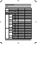
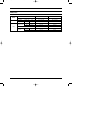
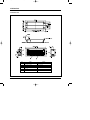
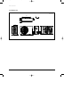
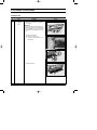
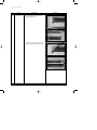
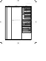
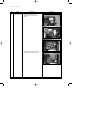
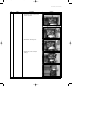
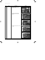
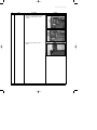
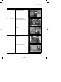
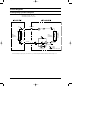
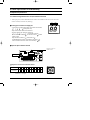
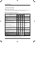
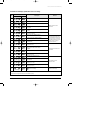
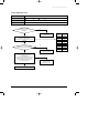
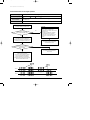
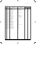
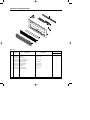
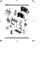
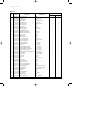
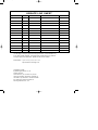
DB98_14088A(1)_CO
7/10/03 2:14 PM
Page 2
CASSETTE TYPE AIR CONDITIONER
INDOOR UNIT
OUTDOOR UNIT
KH026EAM
KH035EAM
UH026EAM
UH035EAM
SERVICE
AIR CONDITIONER
Manual
CONTENTS
1. Product Specifications
2. Disassembly and Reassembly
3. Block Diagrams
4. Control Specification and
4. Troubleshooting
5. Exploded Views and Parts List
6. Wiring Diagrams
7. Schematic Diagrams
DB98_14088A(1)_1
7/10/03 2:13 PM
Page 1
1. Product Specifications
1-1 Table
INDOOR UNIT
KH026EAM
KH035EAM
OUTDOOR UNIT
UH026EAM
UH035EAM
MODEL
Cooling
W
2,800
3,500
Heating
W
2,900
3,800
AC 220~240V, 50Hz
AC 220~240V, 50Hz
Capacity
Power supply
Power input
Cooling / Heating
W
3,500 / 1,200
3,800 / 1,250
Running current
Cooling / Heating
A
4.5 / 4.2
5.4 / 5.7
Hi
r.p.m.
1,070
1,210
Med
r.p.m.
1,000
1,140
Low
r.p.m.
930
1,070
Hi
m3/min
6.84
8.61
Med
m3/min
6.32
8.13
Low
m /min
5.83
7.70
Hi
dB(A)
40
42
Type
ø7.0 SLIT
ø7.0 SLIT
Row x Stages x Fin pitch
2 x 14 x 1.5
2 x 14 x 1.5
Type
Cross flow
Cross flow
Fan speed
(at 0mmAq)
Air
circulation
Noise level
3
(Sound pressure)
Indoor unit
Heat exchanger
Fan
Motor output
W
28
28
H
mm
180
180
W
mm
970
970
D
mm
390
390
kg
Net / Gross
15 / 18
15 / 18
Hi
r.p.m.
750
780
Low
r.p.m.
400
400
dB(A)
52
54
Propeller
Propeller
36
36
Type
Rotary
Rotary
Model
G4A097JU1EP
G8A124JU1EP
810
1,100
Protection
O.L.P
O.L.P
Type
SLIT
SLIT
Row x Stages x Fin pitch
1 x 24 x 1.5
2 x 24 x 1.5
Control
Expansion valve
Expansion valve
890
1,050
Dimensions
Weight
Fan speed
Sound pressure level
Type
Fan
Motor output
Outdoor unit
W
Compressor
Motor output
W
Heat exchanger
Refrigerant
(R410A) Charge
Samsung Electronics
g
1-1
DB98_14088A(1)_1
7/10/03 2:13 PM
Page 2
Table(cont.)
INDOOR UNIT
KH026EAM
KH035EAM
OUTDOOR UNIT
UH026EAM
UH035EAM
MODEL
Outdoor unit
Dimensions
Weight
(H x W x D)
mm
525 x 740 x 230
525 x 740 x 230
kg
Net / Gross
38.5 / 40
28 / 31
Liquid
mm(inch)
6.35 (1.4")
6.35 (1.4")
Gas
mm(inch)
9.52 (3.8")
9.52 (3.8")
Flare
Flare
Pipe O.D. size
Piping
Connection method
Height
m
Max. 15
Max. 15
Pipe length
m
Max. 30
Max. 30
Between
1-2
Samsung Electronics
DB98_14088A(1)_1
7/10/03 2:13 PM
Page 3
1-2 Dimensions
1-2-1 Indoor Unit
(Unit : mm/inch)
Samsung Electronics
Remark
Name
No.
1
Liquid pipe connection
ø6.35(1.4") Nipple
2
Gas pipe connection
ø9.52(3.8") Flare
3
Drain pipe connection
OD29(1
4
Power supply connection
5
Air Inlet
6
Air Outlet
") ID25(1")
1-3
DB98_14088A(1)_1
7/10/03 2:13 PM
Page 4
Product Specifications
1-2-2 Outdoor Unit
(Unit : mm)
11
506
20
270
230
525
740
1-4
57
Samsung Electronics
DB98_14088A(1)_1
7/10/03 2:13 PM
Page 2-1
2. Disassembly and Reassembly
Stop operation of the air conditioner and remove the power cord before repairing the unit.
2-1 Indoor Unit
No
Parts
!
Front Grille
&
Filter
Procedure
Remark
1) Open the Front-Grille by pushing the tabs
on the grille.
IMPORTANT
You must give attention when disassembling
the Front-Grille and must check the safety clips
have been installed. If you don't ensure them,
the Front Grille will drop suddenly and you will
be hurt.
2) Separate the Front Grille.
2-1. Remove the safety clips.
2-2. Open the Front Grille about 45˚ and
pull it forward.
3) Pull out the Air-Filter.
Samsung Electronics
2-1
DB98_14088A(1)_1
7/10/03 2:13 PM
Page 2-2
Disassembly and Reassembly
No
Parts
@
Front Panel
Procedure
Remark
1) Disassemble the 6 screws holding the
panel as shown picture.
2) Separate the Front-Panel pressing the two
hooks on the both sides of the indoor unit.
2-2
Samsung Electronics
DB98_14088A(1)_1
7/10/03 2:13 PM
Page 2-3
Disassembly and Reassembly
No
Parts
#
Ass'y Drain Panel
Procedure
Remark
1) Disassemble 4 screws for Ass'y Drain
Panel around as shown in pictures.
2) Separate Ass'y Drain Panel as shown in
Pictures.
Samsung Electronics
2-3
DB98_14088A(1)_1
7/10/03 2:13 PM
Page 2-4
Disassembly and Reassembly
No
Parts
$
Ass'y Control In
Procedure
Remark
1) Separate the control cover after
disassembling 2 screws as shown in
pictures.
2) Separate the wire connection part of the
Ass'y Main PCB as shown in picture.
2-4
Samsung Electronics
DB98_14088A(1)_1
7/10/03 2:13 PM
Page 2-5
Disassembly and Reassembly
No
Parts
Procedure
Remark
3) Disassemble 2 screws of Case Control
as shown in pictures.
4) Disassemble 1 indicating screw.
5) Separate Ass'y Case Control part
pulling up.
Samsung Electronics
2-5
DB98_14088A(1)_1
7/10/03 2:13 PM
Page 2-6
Disassembly and Reassembly
No
Parts
Procedure
Remark
6) Disassemble 1 indicating screw and
separate earth cable.
7) Disassemble 1 indicating screw and
separate terminal cover as shown in
pictures.
8) Disassemble 2 indicating screws as shown
in pictures.
2-6
Samsung Electronics
DB98_14088A(1)_1
7/10/03 2:13 PM
Page 4-1
Disassembly and Reassembly
No
Parts
Procedure
Remark
9) Disassemble 2 indicating screws of earth
cable and 1 indicating screws of Base
Terminal.
10) Separate Base Terminal as shown in
picture.
Samsung Electronics
2-7
DB98_14088A(1)_1
7/10/03 2:13 PM
Page 4-2
Disassembly and Reassembly
No
Parts
Procedure
%
Ass'y Drain Panel
Sub
1) Separate Ass'y Drain Panel Sub after
disassemble 2 screws both side of it.
^
Ass'y Evap
1) Disassemble 4 screws of Ass'y Evap
around.
Remark
2) Disassemble 2 indicating screws as
shown in picture and separate Ass'y Cabi
Side LF B.
2-8
Samsung Electronics
DB98_14088A(1)_1
7/10/03 2:13 PM
Page 4-3
Disassembly and Reassembly
No
Parts
Procedure
Remark
3) Separate Ass'y Evap pulling up from the
indoor unit as shown in picture.
&
Ass'y Cross Fan
1) Disassemble 3 screws of cover
fan motor and separate cover fan motor.
2) Separate Ass'y Cross Fan as shown in
picture.
*
Ass'y Drain Pump
1) Disassemble 4 indicating screws as shown
in picture.
2) Separate drain hose and separate Ass'y
Drain Pump as shown in pictures.
Samsung Electronics
2-9
DB98_14088A(1)_1
7/10/03 2:13 PM
Page 4-4
2-2 Outdoor Unit
No
Parts
!
Cabinet
Procedure
1) Turn off the unit and remove the power
cable.
2) Remove the top cover.
3) Remove the control box cover.
4) Unplug the ass'y cable.
5) Remove the cabi-side.
6) Remove the cabi-front.
●
@
2-10
Fan Motor
&
Propeller Fan
Remark
When you assemble the parts, check if
the each parts and electric connectors
are fixed firmly.
1) Do Procedure ! above.
2) Remove the nut flange.
(Turn to the right to remove as it is a left
turned screw)
3) Disassemble the propeller fan.
Samsung Electronics
DB98_14088A(1)_1
7/10/03 2:13 PM
Page 3-1
3. Block Diagrams
3-1 Refrigerating Cycle Block Diagrams
❋ Allowable pipe length : Max. 30m
❋ Allowable drop distance : Max. 15m
2-way valve
Filter
Heat
exchanger
(Condenser)
Propeller fan
Heat
exchanger
(Evaporator)
Expansion
valve
Cross fan
Liquid side
Gas side
3-way valve
4-way valve
Cooling
Compressor
Heating
Gas leak check point
❋ When extending the pipe length by more than 5m, 10g of R-410A refrigerant should be refilled per extension length of 1m.
Samsung Electronics
3-1
DB98_14088A(1)_1
7/10/03 2:13 PM
Page 3-2
4. Control Specification & Troubleshooting
4-1 Operation Specification
4-1-1 Initial tracking(Communication check)-E2 indicated if abnormal
1. After input power, outdoor MICOM check the indoor unit installed on the same system and wired
remote controller, transmitter etc.(Tracking)
Left
Right
■ Tracking process marked on display part
• Left numeral is an address that outdoor unit transfers communication.
(Calling indoor unit)
... • Right numeral marks address that is answered.
• During the tracking, left calls indoor unit through
and checks. At this time
... connected indoor unit set on " " and the indoor unit set
address
marked on right.
Right side mark is marked by
when left side is
.
DISPLAY PART (DS1)
• (If SW02(MAIN) that set indoor unit address is controlled to " ",
indoor unit number marked on outdoor unit is marked by " ".)
■ Option set part for Outdoor unit PCB
Setting switch for indoor unit
installation numbers
K2
K4
K1
K3
Data display part
Setting switch for indoor unit installation numbers
Counts of Indoor
Unit Installation
1
2
3
4
5
6
7
8
9
10 11 12 13 14 15
Numbers
of the switch
0/
1
2
3
4
5
6
7
8
9
A
B
C
D
E
F
● Example : When the installed indoor unit is one, control the arrow of switch
forward to ‘0’ or ‘1’ as figure.
4-1
Samsung Electronics
DB98_14088A(1)_1
7/10/03 2:13 PM
Page 3-3
Control Specification & Troubleshooting
4-1-2 Wired remote controller display specification at error occurring
Display
Description
Remarks
Communication error when there is no signal from outdoor unit to wired
remote controller.
Communication error
In case of no signal for
Communication error when there is no answer from wired remote controller
2 minutes
to indoor unit.
Indoor unit float switch error
Indoor unit room temperature sensor open/short error
Indoor unit evaporator temperature sensor open/short error
Indoor unit related error
EEPROM error
EEPROM OPTION error
Fan starting error (1-way cassette model only)
Outdoor unit error display when indoor unit stop
• Outdoor unit sensor error (temperature and pressure)
• Restart failure error
Outdoor related error
(Outdoor related error displays
• Self diagnose of Electronic valve opening /closing 6 times
key error)
• Reverse phase, E2(Communication error)
Overlapping error mark displays error in order, the next error is displayed at error correction.
Samsung Electronics
4-2
DB98_14088A(1)_1
7/10/03 2:13 PM
Page 3-4
4-2 Troubleshooting
When error occurs in air conditioner, error code is displayed on indoor unit display lamp and outdoor unit.
4-2-1 Indoor unit LED error diagnosis
■ Error detection and re operation
• If error occurs during the operation, badness is indicated by LED flickering and all operation is stopped except LED.
• When reoperating by remote controller and switch determine the error mode after normal operation.
■ Indoor unit LED lamp display at error detecting
LED lamp display
Error type
Operation
Timer
Air flow
Remarks
Filter
Power reset
Room Temperature sensor error
(OPEN/SHORT)
Applied indoor unit error display
Indoor heat exchanger temperature sensor error
(OPEN/SHORT)
Applied indoor unit error display
Outdoor temperature sensor error
Condenser temperature sensor error
Discharge temperature sensor error(OPEN/SHORT)
The whole indoor unit error
display Outdoor unit separated
Display
1. No communication for 2 minutes between indoor unit and outdoor unit Indoor unit detection (Communication error over 2
minutes)
2. Indoor unit received communication error signal from outdoor
unit
3. Outdoor unit tracking 3 minutes error
4. After completion of tracking, when outdoor unit transfers communication error due to mismatch installing numbers with communicating numbers (Communication error over 2minutes)
1. Indoor unit error
(Display is unrelated with
operation)
2. Outdoor unit error
(Display is related with
operation)
1. Communication error between indoors
2. Slave of Indoor unit tracking error
Indoor unit error
(Display is unrelated with
operation)
1. The second detection of high temperature of Cond
2. The second detection of high temperature of Discharge
3. Reverse phase error
The whole indoor unit error display
Outdoor unit separated Display
Detection of floating S/W
Error to the set of option for auxiliary control device
EEPROM ERROR
EEPROM OPTION ERROR
: on
: flickering
: off
- If you turn off the air conditioner when LED is flickering, the LED is also turned off.
- If you re-operate the air conditioner, if operates normally at first, then defected an error again.
4-3
Samsung Electronics
DB98_14088A(1)_1
7/10/03 2:13 PM
Page 3-5
Control Specification & Troubleshooting
4-2-2 Outdoor unit display specification at error occurring
Display
NO
Description
DIS1
1
High discharge temperature(Protection control)
2
High condenser temperature(Protection control)
3
Reverse phase detection error (Protection control)
4
Compressor stop due to frozen evaporator of indoor unit
(every times)
5
Error of momentary power failure(Disappears when the unit
is Off/On)
6
During the defrosting operation
(Heat pump model only)
7
Outdoor temperature SENSOR ERROR
(OPEN/SHORT)
8
Condenser temperature SENSOR ERROR
(OPEN/SHORT)
9
Discharge temperature SENSOR ERROR
(OPEN/SHORT)
10
After tracking completion, system down due to
communication error
11
To mismatch the indoor unit number communicated with
setting indoor unit after 5 times tracking
completion
12
Floating switch error from indoor unit
13
Auxiliary control device use option switch setting
control for indoor unit
14
Indoor unit room temperature sensor
open/short error
15
Indoor unit evaporator temperature sensor
open/short error
16
Outdoor unit electronic valve opening error
(Detecting over 1 time)
17
Outdoor unit electronic valve closing error
(Detecting over I time)
18
or
flickering
Remarks
DIS2
Outdoor protection control
related error
Outdoor sensor related error 1
- The whole outdoor unit sensor
error detection should be done
during the indoor unit operation
only.(But ,transferring to communication data by sensing is
allowed at any time.)
Communication and indoor unit
error related
Indoor/Outdoor unit self
diagnosis related
(below -5˚C at cooling),
(over 30˚C at heating)
Operation status display
Display priority order at overlapping error : E1→E4 →E5 →P0 →P0 →P5 →P6 →t1 →t2 →t3 →tu →to →G4 →G5 →E3→qx →rx →ux →K1, 2, 3, 4, 5
- If several indoor unit report the same error, the fast address is priority.
Samsung Electronics
4-4
DB98_14088A(1)_1
7/10/03 2:13 PM
Page 3-6
4-3 Sequence for trouble diagnosis
4-3-1 The freezing of indoor unit heat exchanger
Er → P5 (Detection for the indoor unit freezing)
Outdoor unit display
Indoor unit display
(Operation)
(Timer)
(Airflow)
(Filter)
T_COIL ≤ C x T_AIROUT-a & T_COIL ≤ -5˚C
(The status that time continues for 5 minutes)
Pipe sensor temperature of outdoor heat exchanger : T_COIL
Outdoor temperature : T_AIROUT
C : the open air constant
If T_AIROUT < 0˚C → 0.8 T_AIROUT ≥ 0˚C → 0.6
a : Freezing temperature constant(Default setting value of plant shipping : M=10)
How to determine
- Indoor fan motor lock or badness
- Main PCB badness
Reason of error
To check the indoor unit
detected freezing
To remove the obstacle of indoor unit induction
side and clean the filter
Error reset(K3)
Indoor unit operation
Is operated the indoor unit
fan motor normal?
NO
Is normal the
voltage of the PCB fan motor
output terminal?
(CN72)
YES
YES
Motor exchange
after checking the fan
motor connecting wire
Cooling test operation(K2)
Is normal the high /low pressure
(Refer to pressure table)
YES
NO
To re-operation
after PCB
exchange
NO
To check the refrigerant quantity
(Filling up)
Completion of system check
❋ If the out temperature is so low (Below -5˚C), freezing is possible to indoor unit.
4-5
Samsung Electronics
DB98_14088A(1)_1
7/10/03 2:13 PM
Page 3-7
Control Specification & Troubleshooting
4-3-2 Out temperature sensor
Outdoor unit display
Indoor unit display
Er → t1 (Out temperature sensor OPEN/SHORT error)
(Operation)
(Timer)
(Airflow)
(Filter)
Disconnection and short of out temperature sensor
How to determine
Disconnection or leak of applied sensor
Reason of error
Is not separated the out
temperature sensor connector from
PCB?(CN41)
YES
NO
Re-operation after connection to
connector PCB
To measure the resistance value
between two terminals after
separating the out temperature sensor connector
from PCB
YES
At this time, Is not largely deviate the
resistance value from side table value?
NO
YES
To check the out temperature
sensor is normal or not by use of
out data display part
➞ To check the temperature data is normal or
not after pressing K4 5 times. At this time,
is occurred the difference between the out
temperature and data?
Temperature
(˚C)
Resistance
(kΩ)
70
2.2
60
3.0
50
4.2
40
5.8
30
8.3
20
12.1
10
18.0
0
27.3
-10
43.0
Outdoor unit thermistor
self badness (exchange)
NO
PCB and sensor are normal.
To perform the test
operation by use of K2
YES
Re operation after PCB exchange
Samsung Electronics
4-6
DB98_14088A(1)_1
7/10/03 2:13 PM
Page 3-8
Control Specification & Troubleshooting
4-3-3 Out heat exchanger temperature sensor
Outdoor unit display
Indoor unit display
Er → t2 (Out heat exchanger temperature sensor error(OPEN/SHORT)
(Operation)
(Timer)
(Airflow)
(Filter)
Disconnection and short of out heat exchanger temperature sensor
How to determine
Disconnection or leak of Applied sensor
Reason of error
Is not separated the out
heat exchanger temperature sensor connector
from PCB?(CN41)
YES
NO
Re-operation after connection to
connector PCB
To measure the resistance value
between two terminals after separating the out
heat exchanger temperature sensor connector
from PCB
YES
At this time, Is not largely deviate the
resistance value from side table value?
NO
YES
To check the out temperature
sensor is normal or not by use of
out data display part
➞ To check the temperature data is normal or
not after pressing K4 4 times. At this time,
is occurred the difference between the out
temperature and data?
Temperature
(˚C)
Resistance
(kΩ)
70
2.2
60
3.0
50
4.2
40
5.8
30
8.3
20
12.1
10
18.0
0
27.3
-10
43.0
Out heat exchanger temperature self badness (exchange)
NO
PCB and sensor are normal.
YES
Re operation after PCB exchange
4-7
Samsung Electronics
DB98_14088A(1)_1
7/10/03 2:13 PM
Page 3-9
Control Specification & Troubleshooting
4-3-4 Outdoor discharge temperature sensor error(OPEN/SHORT)
Outdoor unit display
Indoor unit display
Er → t3 (Outdoor discharge temperature sensor OPEN/SHORT error)
(Operation)
(Timer)
(Airflow)
(Filter)
Disconnection and short of out heat exchanger temperature sensor
How to determine
Disconnection or leak of Applied sensor
Reason of error
Is not separated the outdoor
discharge temperature sensor connector
from PCB?(CN42)
YES
NO
Re-operation after connection to
connector PCB
To measure the resistance value
between two terminals after separating the
outdoor discharge temperature sensor
connector from PCB
YES
At this time, Is not largely
deviate the resistance value from
side table value?
NO
Temperature
(˚C)
Resistance
(kΩ)
130
8.9
120
11.2
100
18.5
80
32
60
59
25
200
20
242
10
362
0
553
-10
YES
To check the out temperature
sensor is normal or not by use of out
data display part
➞ To check the temperature data is normal or
not after pressing K4 3 times. At this time,
is occurred the difference between the out
temperature and data?
YES
Out heat exchanger temperature
self badness (exchange)
NO
PCB and sensor are normal.
To perform the test
operation by use of K2
Re operation after PCB exchange
Samsung Electronics
4-8
DB98_14088A(1)_1
7/10/03 2:13 PM
Page 3-10
Control Specification & Troubleshooting
4-3-5 Communication error during the operation
Outdoor unit display
Indoor unit display
Er → E1 (Communication error during the operation)
(Operation)
(Timer)
(Airflow)
(Filter)
In case that the communication is not available for 2 minutes during operation between indoor
and outdoor unit
How to determine
Reason of error
Communication error between indoor unit and outdoor unit
To check the display after
pressing the reset key on outdoor PCB
Multi type
After 2 minutes, to check if PCB address
setting of indoor unit displayed the
communication error among indoor units is
overlapped or not.
(If the indoor unit address is overlapped,
the communication error is occurred.)
- In this case, the communication error is
occurred to over two indoor units set
wrong.
NO
When tracking, is there any
indoor answer from display part?
YES
To measure the 2 lines of outdoor side
by scope after removing the communication line
connecting from outdoor unit to indoor unit
If address is no fault,
to exchange the indoor unit PCB after
communication line check.
NO
At this time, is the voltage
between lines spherical wave over DC ±0.7V
like below figure?
YES
To exchange PCB after checking
the outdoor unit communication line
and connector
After connecting again the communication
line connecting from outdoor unit to indoor unit,
to remove the communication
connector on indoor unit PCB, and find the
indoor unit preventing communication
through connecting the communication
connectors each by each, and then exchange
the indoor unit PCB after line check.
Good
Bad
+0.7V
-0.7V
4-9
Samsung Electronics
DB98_14088A(1)_1
7/10/03 2:13 PM
Page 5-1
Control Specification & Troubleshooting
4-3-6 Communication error between indoor and outdoor after initial power input.
Outdoor unit display
Indoor unit display
Er → E2 (Tracking error)
(Operation)
(Timer)
(Airflow)
(Filter)
How to determine
Mismatching the communicating indoor unit and setting switch indoor numbers When outdoor
tracking
Reason of error
Communication error between the indoor unit and outdoor unit, and installation number switch
setting miss
To check the setting value of
indoor unit installation number setting
switch of outdoor PCB and actual indoor unit
installation numbers
Is equal indoor unit actual
installation number and installation
number setting switch?
If the indoor unit number installed is one, set the
outdoor unit switch forward to "0", "1"
➞ “0” and “1” spell the connection of an indoor unit.
NO
YES
After setting the indoor unit installation setting
number switch correctly, Re-perform the
tracking by pressing the reset key K3 of
outdoor unit PCB
To press the reset key K3 of outdoor unit
PCB and check the display to check the
number of indoor units answering
to the tracking
When tracking, is there any
indoor answer from display part?
YES
To measure the 2 lines of outdoor unit side by
use of scope after removing the communication
line connecting from outdoor unit to indoor unit
NO
Multi type
After 2 minutes, to check if PCB address
setting of indoor unit displayed the communication error among indoor units is overlapped or
not .
(If the indoor unit address is overlapped, the
communication error is occurred.)
- In this case, the communication error is
occurred to over two indoor units set wrong
At this time, is the voltage
between lines spherical wave over
DC ±0.7V ?
YES
If address is no fault,
to exchange the indoor unit PCB after
communication line check.
After connecting again the communication line
connecting from outdoor unit to indoor unit,
to check this communication is reverse or not,
and if there is no fault, to find the indoor unit
preventing communication through connecting
indoor units each by each, and then
exchange the indoor unit PCB after line check
Samsung Electronics
4-10
DB98_14088A(1)_1
7/10/03 2:13 PM
Page 5-2
Control Specification & Troubleshooting
4-3-7 Indoor floating switching error
Outdoor unit display
Indoor unit display
Er → E3 (Indoor floating switching error )
(Operation)
(Timer)
(Airflow)
(Filter)
The status continues over 1 minute that indoor unit floating switch is opened.
How to determine
The rising of water level of drain pan due to the disorder of indoor unit drain pump,
the badness of detection sensor
Reason of error
NO
Is the indoor unit
error occurred cassette type?
Refer to the drain pump
option in the next page
YES
Is the resistance value ∞
when measuring the resistance value of
two terminal after taking out the floating switch
connector connected to indoor unit
PCB? (Open status)
NO
To re-assembly the floating switch
connector and perform the reset of
outdoor power(Required the reset of
indoor unit power)
YES
NO
Is the same error occurred?
Is much the water of drain pan ?
YES
YES
NO
To exchange the indoor unit PCB
Normal operation
To reset the indoor unit power
and check the drain pump operation
To determine the
floating switch bad
To reset the indoor unit
power after exchange
NO
Is operated the drain pump?
YES
NO
Is lowing the water level?
Is the terminal voltage
of drain pump PCB about
AC 220V?
NO
YES
YES
To exchange the drain pump
To exchange the
indoor unit PCB
Normal operation
To exchange the drain pump
4-11
❋ Note : E3 error should be released
when indoor unit power is
reset.
Samsung Electronics
DB98_14088A(1)_1
7/10/03 2:13 PM
Page 6-1
Control Specification & Troubleshooting
■ Indoor floating switching error (cont.)
To check the drain pump option type
YES
NO
Is the switch K4 of OPT3 on
indoor unit PCB OFF position?
YES
To exchange the indoor unit PCB
NO
Is the drain pump and
floating switch mounted?
YES
To reset the indoor unit power after
correction of the switch 4 of
OPT3 on indoor unit PCB to ON position
To check in the same way
to check the cassette type
❋ Note : E3 error should be released
when indoor unit power is
reset.
Samsung Electronics
The position of switch
Function
ON
Non use of the drain pump
OFF
Use of the drain pump
4-12
DB98_14088A(1)_1
7/10/03 2:13 PM
Page 6-2
5. Exploded Views and Parts List
5-1 Indoor Unit
1
24
3
23
3-1
2
9
10
22
11
8
12
13
4
7
14-2
6
14
5
14-1
15
18
16
17
20
19
21
You can search for the updated part code
number through the ITSELF.
URL : http://itself.sec.samsung.co.kr
5-1
Samsung Electronics
DB98_14088A(1)_1
7/10/03 2:13 PM
Page 6-3
Exploded Views and Parts List
■ Parts List
Q'TY
No.
Code No.
Description
Specification
KH026EAM
KH035EAM
1
DB90-00588B
ASS'Y CABI IN
ASS'Y
1
1
2
DB61-00364A
HOLDER DRAIN PUMP
Fire-Resistant P.S(V0)
1
1
3
DB67-00114A
DRAIN PUMP
SAUERMANN
1
1
3-1
DB67-00285A
DRAIN HOSE-SOCKET
POM
1
1
4
DB69-00298A
CUSHION BODY
EPS
1
1
5
DB61-00363A
CASE-FAN SIDE
Fire-Resistant P.S(V0)
1
1
6
DB94-00066A
ASS'Y BEARING
ASS'Y
1
1
7
DB94-00040K
ASS'Y CROSS FAN
ASS'Y
1
1
8
DB31-10078M
MOTOR FAN
PFS040WTVE
1
1
9
DB61-00354A
HOUSING MOTOR
Fire-Resistant P.S(V0)
1
1
10
DB63-00165A
COVER FAN MOTOR
Fire-Resistant P.S(V0)
1
1
11
DB61-00362A
CASE CONTROL
Fire-Resistant P.S(V0)
1
1
12
DB93-00818B
ASS'Y PCB MAIN-IN
ASS'Y
1
1
13
DB63-00167A
COVER CONTROL
ASS'Y
1
1
14
DB96-01188C
ASS'Y EVAP
ASS'Y
1
1
14-1
DB60-00028A
SPACER EVAP
ABS
1
1
14-2
DB32-00035B
THERMISTOR-ASSY
103AT
1
1
15
DB61-00365A
BRACKET TERMINAL
SGCC-M
1
1
16
DB61-00394B
BASE TERMINAL
ABS
1
1
17
DB65-00004P
TERMINAL BLOCK
DAF 2P
1
1
18
DB65-00004C
TERMINAL BLOCK
DAF 4P
1
1
19
DB63-00168A
COVER TERMINAL
Fire-Resistant P.S(V0)
1
1
20
DB94-00084A
ASS'Y DRAIN
ASS'Y
1
1
21
DB94-00094B
ASS'Y DRAIN PAN SUB
ASS'Y
1
1
22
DB95-00131A
ASS'Y SENSOR FLOAT
ASS'Y
1
1
23
DB96-00581A
ASS'Y CHECK VALVE
ASS'Y
1
1
24
DB90-00589A
ASS'Y CABI-SIDE LF
ASS'Y
1
1
Samsung Electronics
5-2
DB98_14088A(1)_1
7/10/03 2:13 PM
Page 6-4
5-2 1-Way Cassette Type (Panel)
4
1
5
2
3
6
7
8
9
10
11
■ Parts List
Q'TY
No.
Code No.
Description
Specification
PK118M
1
DB63-00164A
COVER BLADE
HIPS (UL94-V0)
1
2
DB66-00160A
BLADE-V
HIPS (UL94-V0)
10
3
DB66-00157A
LINK BLADE
POM
2
4
DB63-00163A
COVER PCB CASE
HIPS (UL94-V0)
1
5
DB98-01021A
DISPLAY PCB ASS'Y
6
DB31-10153D
STEP MOTOR
MSFCC20A05
1
7
DB61-00535A
HOLDER MOTOR
HIPS (UL94-V0)
1
8
DB64-00234A
PANEL FRONT
HIPS (UL94-V0)
1
9
DB66-00159A
BLADE-H
HIPS (UL94-V0)
1
10
DB64-00243A
GRILLE FRONT
HIPS (UL94-V0)
1
11
DB64-00244A
GRILLE AIR INLET
PP
1
5-3
1
Samsung Electronics
DB98_14088A(1)_1
7/10/03 2:13 PM
Page 6-5
5-3 Outdoor Unit
18
9
7
9-11
9-1
6
9-2
9-12
17
9-3~9-10
1
1-2
1-1
11
16
15
9-14
9-13
14
12
8
13
3
5-4
4
5-5
10
5-2
2
5-3
5
5-1
Samsung Electronics
5-4
DB98_14088A(1)_1
7/10/03 2:13 PM
Page 6-6
Exploded Views and Parts List
■ Parts List
Q'TY
No.
Code No.
Description
Specification
UH026EAM
UH035EAM
1
DB90-00633K
ASS'Y CABI FRONT
ASS'Y
1
1
1-1
DB63-00385B
GUARD FAN
HSWR,SC-90073T
1
1
1-2
DB64-00439A
CABINET-FRONT
SECC-P
1
1
2
DB60-30020A
NUT FLANGE
2C SM20C M6 NTR
1
1
3
DB67-50063A
PROPELLER-FAN
AS+G/F,20%
1
1
4
DB31-00001C
MOTOR FAN OUT
220/240V, 60/50Hz
1
1
5
DB90-00687E
ASS'Y BASE OUT
ASS'Y
1
1
5-1
DB90-00635A
ASS'Y BASE
ASS'Y
1
1
5-2
DB61-00887A
BRACKET VALVE
SECC-P,T1.6
1
1
5-3
DB61-00802A
BRACKET MOTOR
SGCC-M,T1.2
1
1
5-4
DB73-00070A
GROMMET-ISOLATOR
NR
3
3
5-5
DB72-00693A
SPONGE-COMP BOTTOM
FELT+EVA
1
-
DB72-00725A
SPONGE-COMP BOTTOM
FELT+EVA
-
1
DB98-13314A
ASS'Y COND
ASS'Y
1
-
DB98-13308A
ASS'Y COND
ASS'Y
-
1
7
DB94-00163G
ASS'Y PARTITION
ASS'Y
1
1
8
DB72-00694A
CLOTH COMP SOUND
FELT+EVA
1
-
DB72-00211A
CLOTH COMP SOUND
FELT+PVC SHEET
-
1
9
DB98-13316A
ASS'Y CONTROL OUT
ASS'Y
1
1
9-1
2501-001237
CAPACITOR COMP
35uF 450VAC
1
1
6
9-2
2301-001377
CAPACITOR MOTOR
1.2uF 450VAC
1
1
9-3
DB39-00885A
C/W CCH
YH396-03AV
1
1
9-4
DB39-00893A
WIRE HARNESS-CONNECT
UL1015 AWG18
1
1
9-5
DB39-00894A
WIRE HARNESS C/W COMP
UL1331 AWG14
1
1
9-6
DB39-00895A
WIRE HARNESS C/W CAPACITOR
UL1007 AWG18
1
1
9-7
DB39-00896A
WIRE HARNESS C/W FUSE
UL1007 AWG18
1
1
9-8
DB39-00897A
WIRE HARNESS C/W COMMUNICATION
UL1007 AWG22
1
1
1
9-9
DB39-20469A
C/W GROUND
UL1015/1P,AWG18
1
9-10
DB39-20595A
C/W MOTOR
AWG#16,AWM1015
1
1
9-11
DB61-01499A
CASE PCB
HIPS(V0)
1
1
9-12
DB93-01101B
ASS'Y PCB
ASS'Y
1
1
9-13
DB35-00015W
OLP
RAC12043-9622
1
1
9-14
DB67-60020A
OLP SPRING
STS304
1
1
10
DB99-00329A
ASS'Y VALVE 4WAY
ASS'Y
1
-
DB99-00331A
ASS'Y VALVE 4WAY
ASS'Y
-
1
11
12
DB99-00328A
ASS'Y VALVE EXPANSION
ASS'Y
1
-
DB99-00331A
ASS'Y VALVE EXPANSION
ASS'Y
-
1
G4A097JU1EP
R/COMPRESSOR
1Ph,50Hz,R410A,220-240V
1
1
G8C124JU1EL
R/COMPRESSOR
1Ph,50Hz,R410A,220-240V
-
13
DB60-30028A
NUT-WASHER
HEX 2C MB ZPC
1
1
14
DB63-20002A
GASKET
EPDM
1
1
15
DB63-10165D
COVER TERMINAL
PBT
1
1
16
DB60-30018A
NUT-FLANGE
M5, SM20C
1
1
17
DB63-10443C
COVER E PARTS
ABS
1
1
18
DB90-00634D
ASS'Y CABINET SIDE
ASS'Y (BENDING)
1
1
5-5
Samsung Electronics
DB98_14088A(1)_1
7/10/03 2:13 PM
Page 6-1
6. Wiring Diagrams
6-1 Indoor Unit
Code No : DB98-12856A
This Document can not be used without Samsung's authorization.
Samsung Electronics
6-1
DB98_14088A(1)_1
7/10/03 2:13 PM
Page 6-2
6-2 Outdoor Unit
Code No : DB98-12855A
This Document can not be used without Samsung's authorization.
6-2
Samsung Electronics
DB98_14088A(1)_1
7/10/03 2:13 PM
Page 6-3
7. Schematic Diagrams
7-1 Indoor Unit
This Document can not be used without Samsung's authorization.
Samsung Electronics
7-1
DB98_14088A(1)_1
7/10/03 2:13 PM
Page 6-4
7-2 Outdoor Unit
This Document can not be used without Samsung's authorization.
7-2
Samsung Electronics
DB98_14088A(1)_1
7/10/03 2:13 PM
Page 6-5
MEMO
Samsung Electronics
7-3
DB98_14088A(1)_1
7/10/03 2:13 PM
Page 6-6
MEMO
7-4
Samsung Electronics
DB98_14088A(1)_1
7/10/03 2:13 PM
Page 6-7
MEMO
Samsung Electronics
7-5
DB98_14088A(1)_1
7/10/03 2:13 PM
Page 6-8
UPDATE LOG SHEET
Application date
Page
Part#
Note(Cause & Solution)
Use this page to keep any special servicing information. (Service Bulletin, etc.)
If only parts number changes, Just change parts number directly on parts list.
And if you need more information, please see the service website.
Itself Solution
Integrated technology supporting electronic library
http://itself.sec.samsung.co.kr
Copyright © 2002
By Samsung Electronics Co., Ltd.
All rights reserved.
This manual may not, in whole or in part, be
copied, photocopied, reproduced, translated, or
converted to any electronic or machine readable
from without prior written permission of
Samsung Electronics Co., Ltd.
S/Bulletin#
DB98_14088A(1)_CO
7/10/03 2:14 PM
Page 1
ELECTRONICS
This Service Manual is a property of Samsung Electronics Co., Ltd.
Any unauthorized use of Manual can be punished under applicable
International and/or domestic law.
© Samsung Electronics Co., Ltd. Jul. 2003.
Printed in Korea.
Code No. DB98-14088A(1)