1
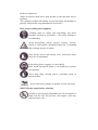
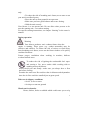
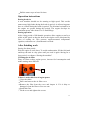
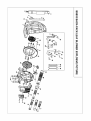
BSB 33
Back-Pack Leaf Blower
PLEASE KEEP THIS MANUAL IN A SAFE PLACE
Contents
1. Guide to using this manual………………………………………....1
2. Safety precautions………………………………………………… .2
3. Maintenance and repair…………………………………………......6
4.Technical specifications…………………………………….…….…7
5. Parts list.…………………………………………………...….….....8
6. Assembling the unit……….………………………………..…….....8
7. Fueling……………………………………………………..….…....9
8. Starting/Stopping…………………………………………….….…11
9. Operating instructions………………………………………….….13
10. After finishing work…………………………………………..….13
11.Storing the machine…………………………………………...…..15
12.Part pictures and lists……………………………………………..17
13.CE conformity……………………………………………………21
14.Notes……………………………………………………………...22
15.Warranty Card…………………………………………………….28
Guide to using this manual
Graphic illustration
All the important parts of this machine are shown and explained in this
manual. The operating and handling instructions are supported by
graphic illustration.
Symbols in text
The individual steps or procedures described in the manual may be
marked in different ways.
·Step or procedure without direct graphic illustration
In this manual step or procedure with direct graphic illustration and
item numbers
Example:
Loosen the screws (1)
Lever (2)
In addition, you should pay special attention to some operating
instructions. They are marked by the symbols described below:
Warning: there is a risk of an accident or personal injury or serious
damage to property.
Warning: there is a risk of damaging the machine or individual
components.
Note or hint: it is not essential for using the machine, but may
improve the operator’s understanding of the situation
and result to use the machine better.
Note or hint: it is correct procedure in order to protect the
environment.
Equipment and features
This manual refers to several models with different features.
Components are not installed in all models and related applications are
marked thus. Such components are available as special accessories
from your dealer.
1
Technology improvements
Our management principle is to improve the quality continually. As a
result, our technology is improved from time to time. If the operating
characteristics or the appearance of your machine differ from those
described in this manual, please contact your dealer for assistance.
Therefore, we cannot be responsible for changes, modifications or
improvements that are not covered in this manual.
Safety precautions
Special safety precautions must be observed when working
with the power tool.
It’s important that you read, fully understand and observe the
following safety precautions and warnings.
-Careless or improper use of any blower may cause serious or fatal
injury.
-Your dealer has shown you how to operate your blower. Observe all
applicable local safety regulations, standards and ordinances.
-Minors should never be allowed to use a blower.
-Bystanders, especially children, and animals should not be allowed in
the area where a blower is in use.
-The operator has the responsibility to avoid injury to the third party
and damage to their property.
-Don’t lend or rent your blower without the owner’s manual. Be sure
that anyone using your blower understands the instructions contained
in this manual.
You must be fit to work with a blower.
·Rested, health and in good physical and mental condition
·If you get tired, take a break in good time
·Do not operate the blower if you are under the influence of any
substance(drugs, alcohol, etc.)which might impair vision, dexterity
or judgment.
-Only accessories supplied are approved for use with your specific
2
model are authorized.
-Other accessories must not be used because of the increased risk of
accidents.
-The company excludes all liability for personal injury and damage to
property caused while using unauthorized accessories.
Wear proper clothing and equipment
Clothing must be sturdy and snug-fitting, but allow
complete freedom of movement— the safety clothing is
recommended.
Avoid loose-fitting jackets, scarves, neckties, jewelry,
flared or cuffed pants, unconfined long hair or anything
that could get into the air intake.
Wear sturdy boots with nonslip soles. Steel-toed safety
boots are recommended.
Wear safety glasses, goggles or a face shield.
Wear sound barriers(ear plugs or ear mufflers) to protect
your hearing.
Wear heavy-duty, nonslip gloves, preferably made of
chrome leather.
Never touch a hot cylinder or muffler ,or burn will result.
Always stop the engine before refueling.
Gasoline is an extremely flammable fuel. Do not smoke or
flame near the fuel. Do not fuel a hot engine—fuel may
spill and cause a fire.
3
Remove the fuel filler cap on the unit carefully so as to allow any
pressure build-up in the tank to release slowly.
Fuel your blower in well-ventilated areas, outdoors only. Wipe off
any spilled fuel before starting and check for leakage.
Take care not to get fuel on your clothing. If this happens, change
immediately.
Unit vibrations can cause an improperly tightened fuel
cap to loosen or come off and spill quantities of fuel.
In order to reduce risk of fuel spillage and fire, tighten fuel cap.
On units with a screw cap: tighten the cap by hand with as
much force as possible. On units with hinged handle on the fuel cap:
Tighten as described in chapter“Fueling”
Check for fuel leakage while refueling and during operation. If
fuel leakage is found, do not start or run the engine until the leak is
fixed.
Store gasoline and oil in properly labelled, approved
safety-type cans.
Transporting the unit
Always stop the engine.
Transporting in a vehicle: Properly protect the unit to prevent
turnover, fuel spillage and damage. When the unit is not in use, put it
down so that it dose not endanger others.
Before starting
Check the following points
·Throttle trigger must move freely and spring back to idle
position when released.
·Stop switch must move easily to “off”.
·Tightness of spark plug cap—if the cap is loose, sparks may
occur and ignite the escaping fuel vapor.
Starting
·Start the engine at least 3m from the fueling spot, outdoors
4
only.
·To reduce the risk of breathing toxic fumes, never start or run
your unit in confined spaces.
·Place the unit on firm ground in an open area.
·Make sure you have good balance and secure footing.
·Hold the unit securely.
Your blower is a one-person unit. Do not allow other persons to be
near the running unit—even when starting.
For specific starting instructions, see chapter “Starting” in the owner’s
manual.
During operation
Warning
Your blower produces toxic exhaust fumes when the
engine is running. These gases (e.g. carbon monoxide) may be
colorless and odorless. To reduce the risk of serious or fatal injury
from breathing toxic fumes, never run the blower indoors of in poorly
ventilated locations.
Ensure proper ventilation when working in trenches, hollows
or otherconfined areas.
To reduce the risk of igniting the combustible fuel vapor
and causing a fire, never smoke while working with or
standing next to the blower.
Always hold your unit firmly—make sure you always have a firm
and secure footing.
Examine the work area: Do not direct the air blast towards bystanders
since the air flow can blow small objects at great speed.
Take care in slippery conditions
·On ice ,in wet or snow
·On slopes or uneven ground
Watch out for obstacles
Roots, ditches, holes or rubbish which could cause you to trip
5
or stumble.
Warning: when spraying
To reduce the risk of inhaling poisonous fumes from chemicals and
exhaust gases, do not operate the blower in confined spaces.
Walk forward only when the unit is running..
In an emergency, release the quick-action buckles, slip out of the
harness and throw off the machine.
After finishing work, drain and clean the container.
Vibrations
Prolonged use of the unit may result in vibration-induced circulation
problems in the hands.
No general recommendation can be given for the length of usage
because it depends on several factors.
The period of usage is prolonged by:
---Hand protection (wearing warm gloves)
---Break
The period of usage is shortened by:
---Any personal tendency to suffer from poor circulation
(symptoms: frequently cold fingers, itching)
---Low temperatures outside
---Gripping force (A tight grip hinders circulation)
Continual and regular users should monitor closely the condition of
their hands and fingers. If any of the above symptoms appear, seek
medical advice.
Maintenance and repairs
Do not attempt any maintenance or repair work not described in the
owner’s manual.
Have such work performed at your service shop only.
Never modify your power tool in any way as this could result in
serious injury.
Always stop the engine and disconnect the spark plug cap before doing
any maintenance or repair work or cleaning the
6
machine.(Exception: carburetor and idle adjustments.)
Always clean dust and dirt off the machine after finishing work.
Do not store or service your unit near any fire or flame
----Check fuel cap regularly for leak
----Use only the approved spark plug (see specifications) and make
sure it is in good condition
----Inspect ignition wires (insulation in good condition, secure
connect)
----To reduce the risk of fire due to ignition outside the cylinder, move
the stop switch to OFF before turning the engine over on the
starter with the spark plug cap removed or the spark plug
unscrewed.
----Check the condition of muffler periodically
----To avoid the risk of fire or hearing loss, do not operate your unit if
the muffler is damaged or missing.
----Never touch a hot muffler or burn will result.
Technical Specifications
Model
BSB33
Displacement(cc)
32.6
Rated Power(KW/r/min)
0.9/8000
Idle Speed
2500±150
Carburetor style
diaphragm
Fuel Ratio
40:1
Fuel tank capacity(L)
3
0.65
Air volume(m /s)
0.2
Overall weight
8
Packing Dimention
420*350*420
7
Parts List
1、 Main unit
2、 Blower pipe A
3、 Blower pipe B
4、 Blower pipe C
5、 Blower pipe D
6、 Control Box
7、 Hose
8、 (40:1)Oil Can
9、 Clip
Assembling the unit
Adjusting the control handle
·Put the unit on your back
·Release the clamp screw
· Slide the control handle along the pleated hose to the most
comfortable position
·Retighten the clamp screw
Adjusting the screw
Adjusting the harness straps
·Pull the end of the straps downward to tighten the harness.
8
Loosening the harness straps
·Lift the tabs of the two sliding adjusters
· Adjust the straps so that the back plate is held firmly and
comfortably against your back.
Adjuster
Fueling
Your engine requires a mixture of gasoline and engine oil. The quality
of these constituents and the mixed ratio has a decisive influence on
the function and service life of the engine.
Unsuitable fuel or lubricants or mixed ratio other than those
specified may result in serious damage to the engine.
Gasoline
Use only regular branded gasoline with a minimum octane rating or
90#. If the octane rating of the regular grade gasoline in your area
is lower, use fuel--leaded or unleaded.
For health and environmental reasons, you should give preference to
unleaded gasoline.
If your machine is equipped with a catalytic converter, you must use
unleaded gasoline.
A few leaded gasoline will greatly reduce the efficiency of the catalytic
converter.
Engine oil
Use only quality two-stroke engine oil.
Other quality two-stroke engine oils must conform to classification
TC.
9
Poor quality gasoline or engine oil may damage the engine, sealing
rings, hoses and the fuel tank.
Mixing fuel
Avoid direct skin contact with gasoline and avoid inhaling gasoline
vapor.
Use a container approved for storing fuel. Pour oil into the container
first, then add gasoline , and mix thoroughly.
Mix ratio
Two-stroke engine oils (classification TC): 40(gasoline):1(oil)
Storing fuel
Fuel ages:
Only mix sufficient fuel for a few months work. Store in approved
safety-type fuel container in a dry and safe location.
·Thoroughly shake the mixture in the container before fueling your
machine. Pressure may build up in the container—open it carefully.
·Clean the fuel tank and container from time to time.
Dispose of cleaning fluid properly at authorized disposal location.
·Before refueling, clean the filler cap and the area around it to ensure
that no dirt falls into the tank.
·Position the unit so that the filler cap is facing up.
Take care not to spill fuel while fueling and do not overfill the tank.
After refueling, tighten down filler cap by hand as securely as
possible.
Change the fuel filter once every year
·Drain the fuel tank
·Use a hook to pull the fuel filter out of the tank
and take it off the hose.
·Push the new filter into the hose.
·Place the filter in the tank.
10
Starting/ stopping the engine
·Observe safety precautions—see chapter (Safety precautions)
·Move the lever to the center position—This is the oil-controlling
setting.
Notes:
· The lever can adjust the airflow volume.
· Put the lever on“0”before switching off the engine, and the engine
will stop automatically.
Big
Small
Throttle Lever
Before starting
Open the choke
Close the choke
The choke lever
·If the engine is cold, close the choke
·If the engine is hot, open the choke fully. Also use this
position when the engine has been running but is still cold.
·Press the oil pump at least 10 times (see the right picture)
·Put the unit on the ground. Check that bystanders are well
Oil pump
clear of the general work area and the nozzle.
·Make sure you have a firm footing: Hold the unit with your left hand on the
11
housing and put one foot against the base plate to prevent it slipping.
·Pull the starter grip slowly with your right hand to 20cm and give it a brisk strong
pull.
·Do not pull the starter rope out all the way as it might otherwise break.
·Do not let the starter grip snap back.
·Guide it slowly back into the housing so that the starter rope can rewind properly.
When the engine begins to fire:
·If the engine is cold, open the choke
Stop Switch
and continue cranking until engine runs
Stop
·If the engine is warm, continue cranking
until engine runs.
Start
As soon as engine runs:
·Move the lever to the center position so that the engine settles down
to idle speed
Stopping the engine
·Move the lever to “0” then the engine will be turned off.
If the engine does not start
If you do not open the choke quickly enough after the engine begins to
fire, the engine will stop.
·Remove the spark plug cap
·Unscrew and dry the spark plug
·Set the stop switch to OFF
·Pull the starter rope several times
to clear the combustion chamber
·Fit the spark plug and reconnect the spark
plug cap
·Move the stop switch to ON
·Open the choke even if the engine is cold
·Now start the engine
Fuel tank run until dry and then refueled
12
·Pull the starter rope at least 10 times
Operation instructions
During break-in
A new machine should not be running at high speed. This avoids
unnecessary high loads during the break-in period. As all moving parts
have to e fitted during the break-in period. The frictional resistances in
the engine are greater during this period. The engine develops its
maximum power after about 5 to 15 tank fillings.
During operation
After a long period of full-throttle operation, allow engine to run for a
while at idle speed so that the heat in the engine can be dissipated by
flow of cooling air. This protects engine-mounted components
(ignition, carburetor etc.) from thermal overload.
After finishing work
Storing for short period:
Wait for engine to cool down. To avoid condensation, fill the fuel tank
and keep the unit in a dry place until you need it again. Storing for a
long period: see chapter “Storing the machine”
Cleaning the air filter
Dirty air filters reduce engine power, increase fuel consumption and
make starting more difficult.
A
If there is noticeable loss of engine power
·Close the choke
·Pull A and remove the air filter cover
·Remove the filter from the cover and inspect it. If it is dirty or
damaged, clean the filter or fit a new one.
·Install the filter
·Fit the cover and tighten the screws
13
Carburetor
General information:
Your carburetor comes from the factory with a standard setting.
This setting provides an optimum fuel-air mixture under most
operating conditions.
The high speed screw alters the engine power output and the
maximum off-road engine speed.
If the setting is too lean, there is a risk of engine damage due to
insufficient lubrication and overheating.
Checking the spark plug
If engine is down on power, difficult to start or runs poorly at idle
speed, first check the spark plug.
·Remove the spark plug, see “starting/stopping the engine”
·Check electrode gap A (0.6-0.7mm) and adjust if necessary, see
“specifications”
Rectify the problems which have
caused fouling of spark plug
----Too much oil in fuel mixture
----Dirty air filter
----Unfavorable running conditions
Fit a new spark plug after about 100 operating hours, or sooner the
electrodes are badly eroded.
·If the spark plug comes with a detachable adapter nut, screw it firmly.
·Press the cap firmly onto the spark plug
14
A
Engine running behavior
If engine running behavior is unsatisfactory even though the air filter
is clean and the carburetor properly adjusted, the cause may be in the
muffler.
Have the muffler checked for contamination by dealer.
Storing the machine
For periods of about 3 months or longer
·Clean the fuel tank
·Run the engine until carburetor is dry---This helps prevent carburetor
diaphragms sticking together.
·Thoroughly clean the machine—pay special attention to the cylinder
and air filter
·Store the machine in a dry, high or locked location out of the reach of
children and other unauthorized persons
·Do not expose the container to direct sunlight for unnecessarily long
period. UV rays can make the container material brittle, which could
result in leaks or breakage.
Minimum wear and avoid damage
Observing the instructions in this manual helps reduce the risk of
unnecessary wear and damage to the power tool.
The power tool must be operated, maintained and stored with the due
care and attention described in this owner’s manual.
The user is responsible for all damage caused by non-observance of
the safety precautions, operating and maintenance instructions in
this manual. This includes in particular:
----Alteration or modifications to the product not approved by dealer.
----Using accessories, power tool accessories or cutting tools not
approved by dealer.
----Using the product for purpose for which it was not designed.
----Using the products for sports or competitive events
----Continuing to use the product with defective components
15
Maintenance and repair
All the operations described in the Maintenance chart must be
performed on a regular basis. If these maintenance operations can
not be performed by the owner, they should be performed by an
authorized dealer.
If these operations are not carried out as specified, the user assumes
responsibility for any damage that may occur. Among other things,
this includes:
----Damage to the engine due to neglect or deficient maintenance,
incorrect carburetor adjustment or inadequate cleaning of cooling air
inlets
----Corrosion and other consequential damage resulting from improper
storage.
16
BSB33 BACKPACK LEAF BLOWER EXPLOSIVE PART LIST
Ser.No.
Erp No.
Part Name
2-1
4305
M6 Nut
2-2
3015
2-3
Qty.
Ser.No.
Erp No.
Part Name
3
2-22
4479
Lock nut M6 GB6177
Washer 6
3
2-23
6425
7789
Harness Assy.
1
2-24
2-4
6549
Blower Pipe C2
1
2-5
0157
Nylon clip
2-6
1222
2-7
Qty.
Qty.
Ser.No.
Erp No.
Part Name
3
2-43
0954
Throttle lever
1
Shield
1
2-44
0995
Retainer lever
1
0210
Starter Assy.
1
2-45
2974
Handle shaft
1
2-25
3004
M5*16 Screw
4
2-46
6536
Washer ¢5 GB/T96
5
4
2-26
6453
Bend Pipe
1
2-47
1173
Back Cushion
1
2-27
6465
Revolving joint
1
2-48
7813
Spring Washer 5
4
6411
Frame
1
2-28
6518
Hose
1
2-49
1227
Spindle sleeve
1
2-8
7986
Tapping screw ST5*16
3
2-29
6527
Blower Pipe A
1
2-50
1309
Throttle wire
2
2-9
6412
Fan guard
1
2-30
6526
Blower Pipe B
1
2-51
0010
Threaded pipe 10
1
2-10
4809
Shock Absorption
3
2-31
6545
Blower Pipe C1
1
2-52
1330
Lead wire
1
2-11
7150
Tapping screw ST5*25
6
2-32
4318
Screw ST2.8X18
5
2-53
0300
Pull-tab,straps
2
2-12
6414
Rear fan cover
1
2-33
2916
Steel clamp
1
2-54
4282
Screw M5*35
4
2-13
7212
Nut M8*1.25
1
2-34
3048
Left control handle
1
2-55
4329
Washer ¢4
2
2-14
4281
Spring Washer 8
1
2-35
2913
Wafer, stop switch
1
2-56
3715
American hose clip
2
2-15
2994
Washer 8
1
2-36
3049
Spindle sleeve
1
2-57
7151
Screw ST4.2*22
4
2-16
6416
Flywheel
1
2-37
1026
Stop switch
1
2-17
2779
Gasket 26*9*1.25
1
2-38
2917
Returnning spring
1
2-18
6420
Front fan cover
1
2-39
3015
Washer ¢6 GB/T96
2
2-19
4419
M5 nut
2
2-40
6074
Retainer ring ¢4 GB/T864
1
2-20
4429
M5*50 Screw
2
2-41
6098
Saddle gasket
2
2-21
4543
Washer ¢8 GB862
2
2-42
3047
Right control handle
1
Screw M5X20 GB/T70.1
1
BSB33 GASOLINE ENGINE
Item No.
Part No.
Part Name
Qty. Item No. Part No.
Part Name
Qty.
1
8817
Valve,fuel cap
1
23
2
8574
Holder,valve
1
3
5689
Rotor
4
3480
5
Item No. Part No.
Part Name
Qty.
0554
Fuel filter comp
1
45
1273
Stopper
1
24
3365
Woodruff key
1
46
2890
Gasket,insulator
1
1
25
3826
Front crankcase
1
47
0377
Insulator
1
Spark plug RCJ6Y
1
26
4538
Retaining ring 28
1
48
1848
Bolt assy M5X20
5
3823
Baffle of cylinder top
1
27
1164
Bolt M5X25
4
49
1154
Gasket,carburetor
1
6
5711
Bolt M5X20
4
28
5599
Oil seal 12X28X7
1
50
8042
Carburetor comp
1
7
3824
Cylinder
1
29
4567
PIN
2
51
1153
Gasket,carburetor
1
8
6168
Gasket,cylinder
1
30
1146
Gasket,muffler
1
52
1141
Clip , pipe
1
9
5607
Ring,piston
2
31
1041
Muffler assy
1
53
1277
Pipe
3
10
5606
Piston
1
32
6132
Heat shield
1
54
2323
Bolt M5X12
2
11
5608
Pin,piston 9X31
1
33
4247
Bolt M5X55
2
55
3357
Washer GB/T896
1
12
5609
Ring, snap
2
34
4451
Washer 4
2
56
1339
Choke
1
13
6616
Needle bearing
1
35
3477
Space,ig coil
2
57
4220
Base, cleaner
1
14
8579
Holder,stopper
1
36
2104
Wire, lead
1
58
4926
Primer pump assy
1
15
3650
Crank shaft assy
1
37
1133
Ignition coil comp.
1
59
6137
Air filter element
1
16
0473
Bearing 6001/P53
2
38
4242
Bolt assy M4X20
2
60
4402
Bolt assy M5X60
2
17
5603
Gasket,crankcase
1
39
6536
Washer 5
8
61
6590
Cover, cleaner
1
18
6268
Cap,fule tank
1
40
7813
Washer 5
8
62
6609
Knob,cover
1
19
3825
Rear crankcase
1
41
4240
Bolt ST3×12
1
20
0047
Oil seal 12X22X7
1
42
4224
Fule tank
1
21
0874
Starter pulley comp.
1
43
964
Chock handle
1
22
1180
Clip , pipe
1
44
0064
Gasket,fuel cap
1
EC DECLARATION OF CONFORMITY
Fujian Jinjiang Sanli Engine Co., Ltd.
Declares that the following equipment manufactured by Fujian Jinjiang Sanli Engine Co.,
Ltd conforms to the following Directive(s):2000/14/EC,2006/42/EC,2004/108/EC and
97/68/EC of the European Parliament and of the council on the approximation of the laws
of the Member States relating to the noise emission in the environment by equipment for
use outdoors.
Equipment Category – Leaf Blower
Product Name/Model: Back Pack Leaf Blower /BSB33 & BSB60
Type/Serial No.: N/A
Net installed power:33cc & 56.5cc
The technical documentation is kept by:
Name:Mr.Liu Qingguo
Company: Fujian Jinjiang Sanli Engine Co., Ltd.
Address: Wuli Industrial Park, Jinjiang, Fujian, 362263,P.R.China
The conformity assessment procedure followed was in accordance with EN ISO3744:1995
and EN ISO 3746:1995, EN 15503:2009, EN ISO 12100-2/A1:2009, EN ISO 14982:1998
and annex V of Directive2000/14/EC.
Notified Body:
TÜV SÜD Product Service GmbH- Ridlerstrasse 65-80339 MÜnchen (Germany)
TÜV SÜD Product Service GmbH- Westendstrasse 65-80686 MÜnchen (Germany)
Measured Sound Power Level: 107dB(A)
Guaranteed Sound Power Level: 111dB(A)
A copy of this certificate has been submitted to the European Commission and to EU
Member State UK.
Place of Declaration: Wuli Industrial Park, Jinjiang, Fujian, 362263,P.R.China
Date: 09/12/2010
Signed by: Mr.Hu Dingsheng
Position in Company : General Engineer
Name and address of manufacturer or Authorised representative:
Fujian Jinjiang Sanli Engine Co.,Ltd.
Wuli Industrial Park, Jinjiang, Fujian, 362263,P.R.China
Notes
BSB 33
Address
WARRANTY CARD
REGISTER YOUR MACHINE TO VALIDATE YOUR WARRANTY.
To validate your warranty, register your equipment with SANLI after its
purchase by returning the warranty card provided at the back of the user's
manual or on the website www.sanli.co.uk/register,www.sanli.fr,www.sanli.com.au
Reference
BSB 33
S/N
By signing,the user
certifies that:
Surname
• the instructions were
provided and he/she has read
the instructions regarding use,
safety and maintenance;
First name
Address
USER
Serial Number
• he/she has been provided with
instructions to use the machine
safely and correctly by the seller;
Town
Postcode
Country
Tel
Mobile
• he/she is aware of the
conditions governing the guarantee
contract and accepts them without
reservation or restriction.
KEEP THIS PART
Reference
BSB 33
Purchase date
Email
DISTRIBUTOR
Customer No:
Sanli UK Ltd
Unit 200 Milton Park Estate
Abingdon Oxfordshire OX14 4TB
www.sanli.co.uk
Imprint / Company Name
Address
SANLI FRANCE SAS
Service garantie 10,Rue
Gutenberg 67610 LAWANTZENAU
www.sanli.fr
Town
Postcode
Check this box if you do not want to receive any
commercial or technical information from SANLI.
Purchase date
Signature
Sanli Australia Development P/L
4/100 Belmore Road,
Riverwood,Nsw 2210
www.sanli.com.au
Serial Number
S/N